US5442700A - Scrambling method - Google Patents
Scrambling methodDownload PDFInfo
- Publication number
- US5442700A US5442700AUS08/310,719US31071994AUS5442700AUS 5442700 AUS5442700 AUS 5442700AUS 31071994 AUS31071994 AUS 31071994AUS 5442700 AUS5442700 AUS 5442700A
- Authority
- US
- United States
- Prior art keywords
- signal
- television
- video
- line
- signals
- Prior art date
- Legal status (The legal status is an assumption and is not a legal conclusion. Google has not performed a legal analysis and makes no representation as to the accuracy of the status listed.)
- Expired - Lifetime
Links
Images


Classifications
- H—ELECTRICITY
- H04—ELECTRIC COMMUNICATION TECHNIQUE
- H04N—PICTORIAL COMMUNICATION, e.g. TELEVISION
- H04N5/00—Details of television systems
- H04N5/222—Studio circuitry; Studio devices; Studio equipment
- H04N5/262—Studio circuits, e.g. for mixing, switching-over, change of character of image, other special effects ; Cameras specially adapted for the electronic generation of special effects
- H04N5/265—Mixing
- G—PHYSICS
- G06—COMPUTING OR CALCULATING; COUNTING
- G06F—ELECTRIC DIGITAL DATA PROCESSING
- G06F3/00—Input arrangements for transferring data to be processed into a form capable of being handled by the computer; Output arrangements for transferring data from processing unit to output unit, e.g. interface arrangements
- G06F3/01—Input arrangements or combined input and output arrangements for interaction between user and computer
- G06F3/048—Interaction techniques based on graphical user interfaces [GUI]
- G06F3/0481—Interaction techniques based on graphical user interfaces [GUI] based on specific properties of the displayed interaction object or a metaphor-based environment, e.g. interaction with desktop elements like windows or icons, or assisted by a cursor's changing behaviour or appearance
- G06F3/04815—Interaction with a metaphor-based environment or interaction object displayed as three-dimensional, e.g. changing the user viewpoint with respect to the environment or object
- H—ELECTRICITY
- H04—ELECTRIC COMMUNICATION TECHNIQUE
- H04N—PICTORIAL COMMUNICATION, e.g. TELEVISION
- H04N19/00—Methods or arrangements for coding, decoding, compressing or decompressing digital video signals
- H04N19/48—Methods or arrangements for coding, decoding, compressing or decompressing digital video signals using compressed domain processing techniques other than decoding, e.g. modification of transform coefficients, variable length coding [VLC] data or run-length data
- H—ELECTRICITY
- H04—ELECTRIC COMMUNICATION TECHNIQUE
- H04N—PICTORIAL COMMUNICATION, e.g. TELEVISION
- H04N19/00—Methods or arrangements for coding, decoding, compressing or decompressing digital video signals
- H04N19/60—Methods or arrangements for coding, decoding, compressing or decompressing digital video signals using transform coding
- H04N19/61—Methods or arrangements for coding, decoding, compressing or decompressing digital video signals using transform coding in combination with predictive coding
- H—ELECTRICITY
- H04—ELECTRIC COMMUNICATION TECHNIQUE
- H04N—PICTORIAL COMMUNICATION, e.g. TELEVISION
- H04N19/00—Methods or arrangements for coding, decoding, compressing or decompressing digital video signals
- H04N19/90—Methods or arrangements for coding, decoding, compressing or decompressing digital video signals using coding techniques not provided for in groups H04N19/10-H04N19/85, e.g. fractals
- H—ELECTRICITY
- H04—ELECTRIC COMMUNICATION TECHNIQUE
- H04N—PICTORIAL COMMUNICATION, e.g. TELEVISION
- H04N21/00—Selective content distribution, e.g. interactive television or video on demand [VOD]
- H04N21/20—Servers specifically adapted for the distribution of content, e.g. VOD servers; Operations thereof
- H04N21/23—Processing of content or additional data; Elementary server operations; Server middleware
- H04N21/234—Processing of video elementary streams, e.g. splicing of video streams or manipulating encoded video stream scene graphs
- H04N21/2347—Processing of video elementary streams, e.g. splicing of video streams or manipulating encoded video stream scene graphs involving video stream encryption
- H—ELECTRICITY
- H04—ELECTRIC COMMUNICATION TECHNIQUE
- H04N—PICTORIAL COMMUNICATION, e.g. TELEVISION
- H04N21/00—Selective content distribution, e.g. interactive television or video on demand [VOD]
- H04N21/20—Servers specifically adapted for the distribution of content, e.g. VOD servers; Operations thereof
- H04N21/23—Processing of content or additional data; Elementary server operations; Server middleware
- H04N21/235—Processing of additional data, e.g. scrambling of additional data or processing content descriptors
- H04N21/2351—Processing of additional data, e.g. scrambling of additional data or processing content descriptors involving encryption of additional data
- H—ELECTRICITY
- H04—ELECTRIC COMMUNICATION TECHNIQUE
- H04N—PICTORIAL COMMUNICATION, e.g. TELEVISION
- H04N21/00—Selective content distribution, e.g. interactive television or video on demand [VOD]
- H04N21/40—Client devices specifically adapted for the reception of or interaction with content, e.g. set-top-box [STB]; Operations thereof
- H04N21/41—Structure of client; Structure of client peripherals
- H04N21/426—Internal components of the client ; Characteristics thereof
- H—ELECTRICITY
- H04—ELECTRIC COMMUNICATION TECHNIQUE
- H04N—PICTORIAL COMMUNICATION, e.g. TELEVISION
- H04N21/00—Selective content distribution, e.g. interactive television or video on demand [VOD]
- H04N21/40—Client devices specifically adapted for the reception of or interaction with content, e.g. set-top-box [STB]; Operations thereof
- H04N21/43—Processing of content or additional data, e.g. demultiplexing additional data from a digital video stream; Elementary client operations, e.g. monitoring of home network or synchronising decoder's clock; Client middleware
- H04N21/435—Processing of additional data, e.g. decrypting of additional data, reconstructing software from modules extracted from the transport stream
- H04N21/4353—Processing of additional data, e.g. decrypting of additional data, reconstructing software from modules extracted from the transport stream involving decryption of additional data
- H—ELECTRICITY
- H04—ELECTRIC COMMUNICATION TECHNIQUE
- H04N—PICTORIAL COMMUNICATION, e.g. TELEVISION
- H04N21/00—Selective content distribution, e.g. interactive television or video on demand [VOD]
- H04N21/40—Client devices specifically adapted for the reception of or interaction with content, e.g. set-top-box [STB]; Operations thereof
- H04N21/43—Processing of content or additional data, e.g. demultiplexing additional data from a digital video stream; Elementary client operations, e.g. monitoring of home network or synchronising decoder's clock; Client middleware
- H04N21/44—Processing of video elementary streams, e.g. splicing a video clip retrieved from local storage with an incoming video stream or rendering scenes according to encoded video stream scene graphs
- H04N21/4405—Processing of video elementary streams, e.g. splicing a video clip retrieved from local storage with an incoming video stream or rendering scenes according to encoded video stream scene graphs involving video stream decryption
- H—ELECTRICITY
- H04—ELECTRIC COMMUNICATION TECHNIQUE
- H04N—PICTORIAL COMMUNICATION, e.g. TELEVISION
- H04N21/00—Selective content distribution, e.g. interactive television or video on demand [VOD]
- H04N21/60—Network structure or processes for video distribution between server and client or between remote clients; Control signalling between clients, server and network components; Transmission of management data between server and client, e.g. sending from server to client commands for recording incoming content stream; Communication details between server and client
- H04N21/61—Network physical structure; Signal processing
- H04N21/6106—Network physical structure; Signal processing specially adapted to the downstream path of the transmission network
- H04N21/6118—Network physical structure; Signal processing specially adapted to the downstream path of the transmission network involving cable transmission, e.g. using a cable modem
- H—ELECTRICITY
- H04—ELECTRIC COMMUNICATION TECHNIQUE
- H04N—PICTORIAL COMMUNICATION, e.g. TELEVISION
- H04N21/00—Selective content distribution, e.g. interactive television or video on demand [VOD]
- H04N21/60—Network structure or processes for video distribution between server and client or between remote clients; Control signalling between clients, server and network components; Transmission of management data between server and client, e.g. sending from server to client commands for recording incoming content stream; Communication details between server and client
- H04N21/61—Network physical structure; Signal processing
- H04N21/6156—Network physical structure; Signal processing specially adapted to the upstream path of the transmission network
- H04N21/6168—Network physical structure; Signal processing specially adapted to the upstream path of the transmission network involving cable transmission, e.g. using a cable modem
- H—ELECTRICITY
- H04—ELECTRIC COMMUNICATION TECHNIQUE
- H04N—PICTORIAL COMMUNICATION, e.g. TELEVISION
- H04N7/00—Television systems
- H04N7/10—Adaptations for transmission by electrical cable
- H—ELECTRICITY
- H04—ELECTRIC COMMUNICATION TECHNIQUE
- H04N—PICTORIAL COMMUNICATION, e.g. TELEVISION
- H04N7/00—Television systems
- H04N7/16—Analogue secrecy systems; Analogue subscription systems
- H04N7/173—Analogue secrecy systems; Analogue subscription systems with two-way working, e.g. subscriber sending a programme selection signal
- H04N7/17309—Transmission or handling of upstream communications
- H04N7/17318—Direct or substantially direct transmission and handling of requests
- H—ELECTRICITY
- H04—ELECTRIC COMMUNICATION TECHNIQUE
- H04N—PICTORIAL COMMUNICATION, e.g. TELEVISION
- H04N7/00—Television systems
- H04N7/16—Analogue secrecy systems; Analogue subscription systems
- H04N7/173—Analogue secrecy systems; Analogue subscription systems with two-way working, e.g. subscriber sending a programme selection signal
- H04N7/17309—Transmission or handling of upstream communications
- H04N7/17336—Handling of requests in head-ends
- H—ELECTRICITY
- H04—ELECTRIC COMMUNICATION TECHNIQUE
- H04N—PICTORIAL COMMUNICATION, e.g. TELEVISION
- H04N7/00—Television systems
- H04N7/16—Analogue secrecy systems; Analogue subscription systems
- H04N7/173—Analogue secrecy systems; Analogue subscription systems with two-way working, e.g. subscriber sending a programme selection signal
- H04N7/17345—Control of the passage of the selected programme
- H—ELECTRICITY
- H04—ELECTRIC COMMUNICATION TECHNIQUE
- H04N—PICTORIAL COMMUNICATION, e.g. TELEVISION
- H04N7/00—Television systems
- H04N7/22—Adaptations for optical transmission
- G—PHYSICS
- G06—COMPUTING OR CALCULATING; COUNTING
- G06F—ELECTRIC DIGITAL DATA PROCESSING
- G06F2203/00—Indexing scheme relating to G06F3/00 - G06F3/048
- G06F2203/048—Indexing scheme relating to G06F3/048
- G06F2203/04802—3D-info-object: information is displayed on the internal or external surface of a three dimensional manipulable object, e.g. on the faces of a cube that can be rotated by the user
- H—ELECTRICITY
- H04—ELECTRIC COMMUNICATION TECHNIQUE
- H04N—PICTORIAL COMMUNICATION, e.g. TELEVISION
- H04N7/00—Television systems
- H04N7/16—Analogue secrecy systems; Analogue subscription systems
- H04N7/173—Analogue secrecy systems; Analogue subscription systems with two-way working, e.g. subscriber sending a programme selection signal
- H04N2007/17372—Analogue secrecy systems; Analogue subscription systems with two-way working, e.g. subscriber sending a programme selection signal the upstream transmission being initiated or timed by a signal from upstream of the user terminal
- H—ELECTRICITY
- H04—ELECTRIC COMMUNICATION TECHNIQUE
- H04N—PICTORIAL COMMUNICATION, e.g. TELEVISION
- H04N7/00—Television systems
- H04N7/16—Analogue secrecy systems; Analogue subscription systems
- H04N7/173—Analogue secrecy systems; Analogue subscription systems with two-way working, e.g. subscriber sending a programme selection signal
- H04N2007/1739—Analogue secrecy systems; Analogue subscription systems with two-way working, e.g. subscriber sending a programme selection signal the upstream communication being transmitted via a separate link, e.g. telephone line
- H—ELECTRICITY
- H04—ELECTRIC COMMUNICATION TECHNIQUE
- H04N—PICTORIAL COMMUNICATION, e.g. TELEVISION
- H04N21/00—Selective content distribution, e.g. interactive television or video on demand [VOD]
- H04N21/20—Servers specifically adapted for the distribution of content, e.g. VOD servers; Operations thereof
- H04N21/21—Server components or server architectures
- H04N21/222—Secondary servers, e.g. proxy server, cable television Head-end
- H04N21/2221—Secondary servers, e.g. proxy server, cable television Head-end being a cable television head-end
- H—ELECTRICITY
- H04—ELECTRIC COMMUNICATION TECHNIQUE
- H04N—PICTORIAL COMMUNICATION, e.g. TELEVISION
- H04N21/00—Selective content distribution, e.g. interactive television or video on demand [VOD]
- H04N21/20—Servers specifically adapted for the distribution of content, e.g. VOD servers; Operations thereof
- H04N21/23—Processing of content or additional data; Elementary server operations; Server middleware
- H04N21/238—Interfacing the downstream path of the transmission network, e.g. adapting the transmission rate of a video stream to network bandwidth; Processing of multiplex streams
- H04N21/2383—Channel coding or modulation of digital bit-stream, e.g. QPSK modulation
- H—ELECTRICITY
- H04—ELECTRIC COMMUNICATION TECHNIQUE
- H04N—PICTORIAL COMMUNICATION, e.g. TELEVISION
- H04N21/00—Selective content distribution, e.g. interactive television or video on demand [VOD]
- H04N21/20—Servers specifically adapted for the distribution of content, e.g. VOD servers; Operations thereof
- H04N21/23—Processing of content or additional data; Elementary server operations; Server middleware
- H04N21/238—Interfacing the downstream path of the transmission network, e.g. adapting the transmission rate of a video stream to network bandwidth; Processing of multiplex streams
- H04N21/2385—Channel allocation; Bandwidth allocation
- H—ELECTRICITY
- H04—ELECTRIC COMMUNICATION TECHNIQUE
- H04N—PICTORIAL COMMUNICATION, e.g. TELEVISION
- H04N21/00—Selective content distribution, e.g. interactive television or video on demand [VOD]
- H04N21/20—Servers specifically adapted for the distribution of content, e.g. VOD servers; Operations thereof
- H04N21/25—Management operations performed by the server for facilitating the content distribution or administrating data related to end-users or client devices, e.g. end-user or client device authentication, learning user preferences for recommending movies
- H04N21/258—Client or end-user data management, e.g. managing client capabilities, user preferences or demographics, processing of multiple end-users preferences to derive collaborative data
- H04N21/25866—Management of end-user data
- H—ELECTRICITY
- H04—ELECTRIC COMMUNICATION TECHNIQUE
- H04N—PICTORIAL COMMUNICATION, e.g. TELEVISION
- H04N21/00—Selective content distribution, e.g. interactive television or video on demand [VOD]
- H04N21/20—Servers specifically adapted for the distribution of content, e.g. VOD servers; Operations thereof
- H04N21/25—Management operations performed by the server for facilitating the content distribution or administrating data related to end-users or client devices, e.g. end-user or client device authentication, learning user preferences for recommending movies
- H04N21/266—Channel or content management, e.g. generation and management of keys and entitlement messages in a conditional access system, merging a VOD unicast channel into a multicast channel
- H04N21/2665—Gathering content from different sources, e.g. Internet and satellite
- H—ELECTRICITY
- H04—ELECTRIC COMMUNICATION TECHNIQUE
- H04N—PICTORIAL COMMUNICATION, e.g. TELEVISION
- H04N21/00—Selective content distribution, e.g. interactive television or video on demand [VOD]
- H04N21/20—Servers specifically adapted for the distribution of content, e.g. VOD servers; Operations thereof
- H04N21/25—Management operations performed by the server for facilitating the content distribution or administrating data related to end-users or client devices, e.g. end-user or client device authentication, learning user preferences for recommending movies
- H04N21/266—Channel or content management, e.g. generation and management of keys and entitlement messages in a conditional access system, merging a VOD unicast channel into a multicast channel
- H04N21/2668—Creating a channel for a dedicated end-user group, e.g. insertion of targeted commercials based on end-user profiles
- H—ELECTRICITY
- H04—ELECTRIC COMMUNICATION TECHNIQUE
- H04N—PICTORIAL COMMUNICATION, e.g. TELEVISION
- H04N21/00—Selective content distribution, e.g. interactive television or video on demand [VOD]
- H04N21/40—Client devices specifically adapted for the reception of or interaction with content, e.g. set-top-box [STB]; Operations thereof
- H04N21/43—Processing of content or additional data, e.g. demultiplexing additional data from a digital video stream; Elementary client operations, e.g. monitoring of home network or synchronising decoder's clock; Client middleware
- H04N21/438—Interfacing the downstream path of the transmission network originating from a server, e.g. retrieving encoded video stream packets from an IP network
- H04N21/4382—Demodulation or channel decoding, e.g. QPSK demodulation
- H—ELECTRICITY
- H04—ELECTRIC COMMUNICATION TECHNIQUE
- H04N—PICTORIAL COMMUNICATION, e.g. TELEVISION
- H04N21/00—Selective content distribution, e.g. interactive television or video on demand [VOD]
- H04N21/40—Client devices specifically adapted for the reception of or interaction with content, e.g. set-top-box [STB]; Operations thereof
- H04N21/43—Processing of content or additional data, e.g. demultiplexing additional data from a digital video stream; Elementary client operations, e.g. monitoring of home network or synchronising decoder's clock; Client middleware
- H04N21/438—Interfacing the downstream path of the transmission network originating from a server, e.g. retrieving encoded video stream packets from an IP network
- H04N21/4383—Accessing a communication channel
- H—ELECTRICITY
- H04—ELECTRIC COMMUNICATION TECHNIQUE
- H04N—PICTORIAL COMMUNICATION, e.g. TELEVISION
- H04N21/00—Selective content distribution, e.g. interactive television or video on demand [VOD]
- H04N21/40—Client devices specifically adapted for the reception of or interaction with content, e.g. set-top-box [STB]; Operations thereof
- H04N21/47—End-user applications
- H04N21/482—End-user interface for program selection
- H04N21/4821—End-user interface for program selection using a grid, e.g. sorted out by channel and broadcast time
- H—ELECTRICITY
- H04—ELECTRIC COMMUNICATION TECHNIQUE
- H04N—PICTORIAL COMMUNICATION, e.g. TELEVISION
- H04N21/00—Selective content distribution, e.g. interactive television or video on demand [VOD]
- H04N21/60—Network structure or processes for video distribution between server and client or between remote clients; Control signalling between clients, server and network components; Transmission of management data between server and client, e.g. sending from server to client commands for recording incoming content stream; Communication details between server and client
- H04N21/65—Transmission of management data between client and server
- H04N21/654—Transmission by server directed to the client
- H—ELECTRICITY
- H04—ELECTRIC COMMUNICATION TECHNIQUE
- H04N—PICTORIAL COMMUNICATION, e.g. TELEVISION
- H04N21/00—Selective content distribution, e.g. interactive television or video on demand [VOD]
- H04N21/60—Network structure or processes for video distribution between server and client or between remote clients; Control signalling between clients, server and network components; Transmission of management data between server and client, e.g. sending from server to client commands for recording incoming content stream; Communication details between server and client
- H04N21/65—Transmission of management data between client and server
- H04N21/658—Transmission by the client directed to the server
- H—ELECTRICITY
- H04—ELECTRIC COMMUNICATION TECHNIQUE
- H04N—PICTORIAL COMMUNICATION, e.g. TELEVISION
- H04N5/00—Details of television systems
- H04N5/44—Receiver circuitry for the reception of television signals according to analogue transmission standards
- H04N5/445—Receiver circuitry for the reception of television signals according to analogue transmission standards for displaying additional information
- H04N5/45—Picture in picture, e.g. displaying simultaneously another television channel in a region of the screen
Definitions
- the present inventionrelates to cable television systems, particularly those having two-way communications capability with the user.
- Bandwidth problemshave long restricted the ability of cable television systems to provide information services to subscribers.
- a coaxial cable systemmay permit a cable system operator to provide, for example, 50 television channels, each 6 MHz wide, with a total bandwidth of 300 MHz, this total bandwidth is insufficient to permit an arrangement wherein each subscriber may have, in addition to these 50 channels, an interactive information service that functions independently of interactive information services to all other subscribers and provides full color video, motion typical of movies or television, and sound.
- a subscriber on a cable systemobtains information services over a communication path that starts at the headend, proceeds over one of typically a number of trunks, and then over one of a number of feeders, and then over one of a number of taps.
- Each feedermay have, for example, fifty or more subscribers, and each trunk might serve a hundred or more feeders. The result is that 5000 subscribers per trunk is not atypical.
- fiber optic trunkscan assist in providing additional bandwidth, but to the extent that coaxial cable secondary trunks and feeders are used in a hybrid fiber-cable system, bandwidth limitations may continue to pose problems. While video compression schemes may assist in bringing the bandwidth requirements within more practical limits, each subscriber would then need to be provided with his own decompression unit.
- Another problemlies in how to handle the switching and computing demands on the headend to provide separate and private information service to potentially hundreds of thousands of subscribers simultaneously.
- the present inventionprovides in a preferred embodiment a system that achieves distribution of conventional cable services in traditional manners while providing interactive television information services on a demand basis using a switching arrangement, and it does so while surprisingly permitting both types of service to be accessed, as in the past, by the single action of channel selection.
- the inventionprovides an interactive television information system, for providing interactive cable television service when coupled to a cable television system having (i) an information source available at a headend for supplying a plurality of information services and (ii) an information service distribution network for delivering the information services to subscriber televisions.
- the interactive television systemhas a plurality of home interface controllers.
- One such home interface controlleris associated with each subscriber television and provides an output in communication with the subscriber television and has (i) a signal input for television information signals and an input selection arrangement for selecting a given one of the television information signals at the signal input, (ii) a channel selection arrangement for permitting a user to select an apparent channel, and (iii) a data transceiver operative over a data communications link.
- the embodimentalso has a node, in television communication with the information source over a first path of the network and with a group of the home interface controllers means over a second path of the network, and in data communications with the home interface controllers over the data communications link.
- the nodeselects and provides information services obtained from the information source to each home interface controller in the group based on data obtained over the data communications link from each such home interface controller.
- the node and each home interface controllerare so arranged that when any of a first group of apparent channels is selected on a given one of the home interface controllers, the node provides to it different information services on different apparent channels in the group all via the same television information signal selected by the input selection arrangement of such given home interface controller at a single carrier frequency for such given home interface controller.
- the channel selection arrangement in each home interface controllerincludes an arrangement for causing each selected channel in a second group of apparent channels to correspond to a different selected carrier frequency of a television information signal at the signal input. In this manner, selecting different apparent channels can also be used to cause the selection of different conventional cable channels.
- channel selectionpermits the user to select any information service, regardless whether it is conventional or interactive.
- the nodeincludes an activity detection arrangement for determining whether a given home interface controller is to be placed in an interactive mode.
- the nodealso includes a signal assignment arrangement for causing, on an affirmative determination by the activity detection arrangement, the input section arrangement of the given home interface controller to select a given television information signal present at the signal input.
- signal assignmentis accomplished on a demand basis for those home interface controllers determined to be placed in an interactive mode. When the demand exceeds the supply, the assignment is achieved with rules for resolving the contention, for example, by permitting the first home interface controller to keep its assigned frequency until the activity detection arrangement detects that the interactive mode is no longer in effect.
- the distribution networkmay include a plurality of express trunks.
- Each trunkhas a first bandwidth portion carrying non-interactive television information services that are substantially identical in nature and in bandwidth allocation among all trunks.
- a second bandwidth portion of each trunkcarries television information services on a demand basis established by subscriber usage of the home interface controllers utilizing the trunk for service.
- the data communications linkmay include a return path, from each home interface controller in a collection of neighboring home interface controllers, to the node in which a common trunk line is utilized for all of the home interface controllers in the collection.
- This embodimentmay further utilize a main trunk carrying television information signals for non-interactive information services from the headend to each of the express trunks.
- an interactive trunkmay carry television information signals for information services on a demand basis from the headend to each of the express trunks.
- a splittersplits from the interactive trunk the television signals for information services on a demand basis for each of the express trunks.
- a group of couplerscouples the signals from the main trunk and the splitter to feed each of the express trunks.
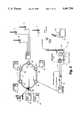
- FIG. 1is a schematic of an interactive television information system in accordance with a preferred embodiment of the present invention, showing relations with national and regional processing centers;
- FIG. 2is a schematic showing the manner in which a multiheadend system with fiber optic interconnection may be employed to provide interactive television service in accordance with an embodiment of the invention
- FIG. 3is a schematic showing an embodiment similar to that shown in FIG. 2, but in which a headend may have wireless communication with subscribers;
- FIG. 4is a schematic showing a mixed fiber optic coaxial cable system in accordance with a preferred embodiment of the present invention.
- FIG. 5illustrates the general architecture of outbound signal flow and two-way control in a system in accordance with a preferred embodiment of the present invention
- FIG. 6illustrates the manner in which the architecture of a system similar to that of FIG. 5 uses controls to handle a wide range of information services in both analog and digital formats and distribution arrangements;
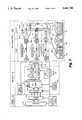
- FIG. 7provides further detail of the system of FIG. 6;
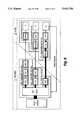
- FIG. 8shows the signal processing aspects of the system of FIG. 7
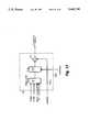
- FIG. 9shows detail of the splitter and combiner of FIG. 7;
- FIG. 10shows the allocation of frequency bands in the express trunks of FIG. 9;
- FIGS. 11A-11Dshow the structure of a chassis in accordance with a preferred embodiment of the present invention for holding multimedia controllers (MMCs) and modulator cards constituting components of the system illustrated in FIG. 7;
- MMCsmultimedia controllers
- FIG. 15illustrates the structure of the data communications link at the headend (node) of the system of FIG. 7;
- FIG. 16illustrates the structure of the encoder/modulator of FIG. 12
- FIG. 17illustrates the structure of the video processor of FIG. 16
- FIG. 18illustrates the structure of the sync generator lock and scrambler timing section of FIG. 16
- FIG. 19illustrates the structure of the audio processor section of FIG. 16
- FIG. 20illustrates the structure of the rf upconverter section of FIG. 16
- FIG. 21illustrates the structure of a scrambler for use with the modulator of FIG. 16
- FIG. 22illustrates the seed data timing used in connection with the scrambler of FIG. 21;
- FIG. 23illustrates the structure of a descrambler suitable for use in a home interface controller in accordance with a preferred embodiment of the present invention for descramling a video signal that has been scrambled by a system in accordance with FIG. 21;
- FIG. 24illustrates an alternative scrambling system
- FIG. 25illustrates a descrambling system for use with video that has been scrambled by the system in accordance with FIG. 24;
- FIG. 26illustrates the input and output structure of a home interface controller in accordance with a preferred embodiment of the present invention
- FIG. 27illustrates an embodiment of the controller of FIG. 26
- FIGS. 28 and 29illustrate embodiments of digital decompression and multimedia versions of the controller of FIG. 26;
- FIG. 30illustrates an alternative embodiment to the system of FIG. 7 in which the node is disposed at a feeder
- FIG. 31shows the bandwidth usage in a system in accordance with that of FIG. 30;
- FIG. 32shows the general architecture of outbound signal flow and two-way control in a system in accordance with the embodiment of FIG. 30;
- FIGS. 35-41illustrate use of the carousel menu system and of the manner in which the invention in a preferred embodiment provides interaction with the user.
- the terms “cable television environment” and “cable television system”include all integrated systems for delivery of any information service to subscribers for use in connection with their televisions. These include conventional cable television systems utilizing coaxial cable for distribution primarily of broadcast and paid television programming, cable television systems using fiber optics and mixed fiber optic-coaxial cable, as well as other means for distribution of information services to subscribers.
- the term “information service”includes any service capable of being furnished to a television viewer having an interface permitting (but not necessarily requiring) interaction with a facility of the cable provider, including but not limited to an interactive information service, video on demand, local origination service, community event service, regular broadcast service, etc.
- “Television communication”means providing an information service via a television information signal.
- a “television information signal”is any signal that may be utilized by a television for video display, regardless of the form, including a standard NTSC-modulated rf carrier, an MPEG-compressed digital data stream, or any other format.
- "Interactive television service”means an information service that utilizes an interface affording two-way communication with a facility of the cable provider. When a node is said to be in an "interactive mode,” it means that the node is providing an information service to the home interface controller; the home interface controller may, but need not, be furnishing data to the node as to what information service to provide.
- FIG. 1there is shown the relationship of a cable television system in accordance with the present invention to regional and national processing systems.
- a headend 11is in communication with a plurality of nodes 12 that in turn communicate with set top units 13, which below are referred to as "home interface controllers".
- Each of these home interface controllershas a remote control 14 operable by the user.
- Each headend 11may obtain items for use in providing an information service from a regional processing center 15, which in turn may obtain some information services from a national processing center 16.
- the information servicesmay include a wide range of offerings, such as classified advertising services, newspapers, advertising, televised catalogue ordering, video on demand or near video on demand, etc.
- Information services that are conventional television network programmingmay also be distributed from the national and regional processing centers.
- FIG. 2is a schematic showing the manner in which a multiheadend system with fiber optic interconnection may be employed to provide interactive television service in accordance with an embodiment of the invention.
- a pair of fiber optic cables 21 and 22provide information services in clockwise and counter-clockwise directions (for redundancy in the event of disruption of the cables)from super headend 28 to headend clients 24 serving a number of cities 23.
- the super headendin turn may obtain conventional broadcast services as well as interactive information services from satellite receiver 27, and other information services from servers 25 from regional processing centers, as well as WAN and interexchange (IXC) facilities 26.
- Each headend client 24may contain an interactive service node, here designated by the trademark ISX, a trademark of ICTV, the assignee herein.
- FIG. 3is a schematic showing an embodiment similar to that shown in FIG. 2, but in which a headend 24 may have two-way wireless communication using transceiver facilities 31 with subscribers.
- a transceiver facility 31may include a high gain antenna system 31a communicating with a transceiver 36 coupled to a television 37 at each subscriber location.
- the antenna system 31aradiates rf signals fed by transmitter 31b; the antenna 31a also receives signals from the subscriber transceivers and feeds them to receiver 31c.
- the transmitter 31b and the receiver 31care linked to fiber optic receiver 32 and fiber optic transmitter 33 respectively, which in turn communicate with the headend 24 over optical fibers 34 and 35.
- FIG. 4is a schematic showing a mixed fiber optic coaxial cable system in accordance with a preferred embodiment of the present invention.
- main fiber trunks 42a carrying conventional cable and broadcast programminggo to optical receiver 43a, from which coaxial trunks 44A (express trunk A), 44B (express trunk B), and 44C (express trunk C) derive regular cable television programming signals.
- coaxial trunks 44A (express trunk A), 44B (express trunk B), and 44C (express trunk C)derive regular cable television programming signals.
- Each express trunkhas a first bandwidth portion carrying these non-interactive television information services that are substantially identical in nature and in bandwidth allocation among all express trunks.
- An interactive fiber trunk 42b in FIG. 4carries desired interactive information services in the outbound direction that are not provided over main fiber trunks 42a, and these information services are fed into optical receiver 3b.
- the electrical output of the optical receiver 43bincludes information services in separate spectral portions for each of express trunks A, B, and C. This output is provided to hub splitter 46.
- the information services for each of express trunks A, B, and Care then translated into common spectral portions by hub splitter 46, and then fed to the designated trunks, where they are coupled to the conventional signals via couplers at locations 45a, 45b, and 45c on trunks 44a, 44b, and 44c respectively.
- each of these trunksoccupy similar spectral regions, their information content is different, since the information content of the information services on trunk A is supplied on demand to the home interface controllers served by trunk A, the content on trunk B is supplied on demand to the home interface controllers served by trunk B, and the content on trunk C is supplied on demand to the home interface controllers served by trunk C.
- a second bandwidth portion of each express trunkcarries television information services on a demand basis established by subscriber usage of the home interface controllers utilizing the trunk for service.
- the path of inbound data from the each express trunk 44A, 44B, and 44Cis from a splitter at each of locations 45a, 45b, and 45c respectively to hub combiner 47.
- the inbound datalike the outbound interactive television information services, on each of the express trunks occupy similar spectral regions, although the data on each express trunk have different information content reflecting the particular demands made by the home interface controllers using each particular express trunk.
- the inbound data from each trunkare frequency shifted by hub combiner 47 in the manner described in further detail in connection with FIG. 9 to cause the data from these trunks to occupy separate spectral regions, and the output of the combiner 47 feeds optical transmitter 42c.
- the optical transmitter 43cfeeds the optical fiber trunk 42c to provide a common trunk return path, for all the home interface controllers served by express trunks 44A, 44B, and 44C, for the interactive headend 41.
- FIG. 5illustrates the general architecture of outbound signal flow in a system in accordance with a preferred embodiment of the present invention.
- a variety of sources of information servicesare available from satellites, antennas, servers, and gateways, and they are routed to subscribers via routing switchers 52. A portion of these information services may, but need not, be provided to all subscribers as basic non-interactive service.
- the routing switchers 52feed appropriate modular multimedia controllers 53 (MMCs) which may provide appropriate processing for providing the service in question to each subscriber. Differently configured cards are used depending on the nature of the information service.
- MMCsmodular multimedia controllers
- an individual MMC 53is assigned on a demand basis to each requesting home interface controller, which is in data communication with MMC, and the MMC provides interactive television information service.
- Post switchers 54switch the MMC outputs to appropriate modulators 55, which are in turn grouped so that their outputs feed rf combiners used for each fiber optic transmitter 57 and associated optical fiber 58.
- two-way controlis exerted over the outbound signal flow from end to end.
- FIG. 6illustrates the manner in which the architecture of a system similar to that of FIG. 5 may handle a wide range of information services in both analog and digital formats and distribution arrangements.
- a super headend 28may obtain some information services via television receive only (TVRO) system 61a and downlink 62a, as well as over line 61b using, for example, T1 or T3 bands or ATM digital protocols and gateways 62b.
- the super headend 28furnishes information services 64 via switch 65 to the headend 11.
- These information servicesmay include video on demand, near video on demand, and multimedia presentations. They are provided under the general control of control manager 62c over control bus 63a.
- a central databasemay be maintained on server 64a for all subscribers as to the types of service subscribed to and terms for delivery of service, and the delivery of services to the subscribers is monitored and controlled over the control bus 63a by service manager 63.
- the control manageralso has supervisory control on bus 63a over the input switch 66 to headend 11.
- This switch 66having an input from the output switch 65 of the super headend 28, feeds the analog MMCs 67a for analog signals in conventional formats and digital MMCs 67b for signals in digital formats.
- the MMC outputsare then subjected to modulators for appropriate frequency translation (item 68a) and to distribution 68b over the cable network to subscribers having analog converters 69a or digital converters 69b.
- Interactive information serviceis enabled by the net manager 66a, which maintains two-way data communication over gateway 66b with each of the converter types 69a and 69b.
- FIG. 7provides further detail of a system in accordance with FIGS. 4-6.
- the information sources 51 from the super headend 28feed its switch 65, the output of which is directed to the headend 11, which contains, in a node 77, input switch 66 feeding a series of MMCs, usage of which is allocated on a demand basis.
- conventional cable broadcast channelsare routed over main fiber trunk 42a to express trunks 44A, 44B, and 44C.
- An interactive fiber trunk 42bcarries interactive channels (here called “virtual channels” for reasons that will be described below) to splitter 46 for coupling at 45a, 45b, and 45c to express trunks 44A, 44B, and 44C.
- Combiner 7takes inbound data from each of the express trunks for delivery over common data fiber trunk 42c to the node at the headend.
- Analog television information signals from appropriate analog MMCsare processed by scrambling at 73a and modulators at 73b, whereas digital television information signals from appropriate digital MMCs are processed by combining them into a composite QAM (quadrature amplitude modulation) signal before going to modulators at 73b.
- the modulatorsare preferably capable of modulating a carrier that is tunable by the network manager 66a, so that any given modulator may be configured to best handle demands placed on the system. (In FIG.
- the modulatorsare associated with carriers at dedicated frequencies, and the inputs to the modulators are varied by switch 54.
- some of the cable broadcast channels 72may alternatively be provided, over path 72a to the MMCs, as information services on demand furnished by node 77.
- the path 72apermits the MMCs operating interactively to permit a subscriber to make overlays on otherwise conventional cable television programming.
- the outputs of items 73bare then combined by combiner 73 and fed to the interactive trunk 42b.
- the cable distribution plant 68bincludes bridger amplifiers 74, feeders 74 a, feeder amplifiers 74b, and cable drops such as 75a, 75b, and 75c serving homes 76a, 76b, and 76c.
- the information servicescan be provided to a subscriber over virtual channels in which the channel number changes for different interactive information services, even though the various information services may be provided over a fixed frequency input to the set top, with the control data from subscriber's set top causing the headend to supply a different information service as the subscriber appears to be changing the channel. This feature is described in further detail below.
- the modular structure of the node 77 and the arrangement of the distribution plant 68bpermit serving simultaneously homes such as 76a with a conventional converter, 76b with a digital set top having MPEG decompression, and 76c with a digital set top having multimedia capability achieved with a home-based central processing unit.
- Each homehas a home interface controller operating as part of the set top configured as described below.
- FIG. 8shows the signal processing aspects of the system of FIG. 7. This figure does not show the distribution system, and therefore applies equally to telephone or cable distribution architectures.
- An analog MMC 82a in the node at headend 11will typically pick off, under control of a central processing unit (CPU), a television information signal in digital form from switch 66 and then decompress the signal, subject it to appropriate frequency translation by a modulator and provide over the distribution system to homes where a conventional set top in block 81a can permit the signal to be demodulated for display by the television.
- a digital MMC 82b in the node at headend 11also operates under control of a CPU, but does not need to decompress the signal. The signal is subjected to appropriate frequency translation and then distributed to the home.
- the signalis demodulated and decompressed at the set top for display by the television.
- itis primarily frequency translation that needs to be provided at the headend node, which is achieved by gateway card 82c, and the set top in block 81c includes the CPU for processing of the signal from the headend.
- FIG. 9shows detail of the splitter 46 and combiner 47 of FIGS. 4 and 7.
- Signals fed into splitter 46include spectral regions for television information signals 91A for information services on demand for subscribers served by express trunk 44A and for outbound data 95A for providing interactive service to these subscribers.
- spectral regions for television information signals 91Bfor information services on demand for subscribers served by express trunk 44B and for outbound data 95B for providing interactive service to these subscribers;
- television information signals 91Cfor information services on demand for subscribers served by express trunk 44C and for outbound data 95C for providing interactive service to these subscribers.
- the signals in these spectral regionsare subject to frequency translation so that corresponding bands 92A, 92B, and 92C in each of express trunks 44A, 44B, and 44C respectively carry television information signals for information services on demand to subscribers served by these trunks.
- Frequency translationis also used so that corresponding bands 94A, 94B, and 94C carry outbound (downstream) data for providing interactive service to these subscribers in each of express trunks 44A, 44B, and 44C respectively.
- conventional cable channelsoccupy corresponding bands (here shown as item 90) in each of the express trunks.
- Inbound (upstream) data for interactive serviceare handled by the hub combiner in the reverse manner.
- the datainitially occupy corresponding bands 93A, 93B, and 93C on trunks 44A, 44B, and 44C, and are subject to frequency translation by combiner 47 so that the inbound data from trunk 44A occupy a first spectral region 96A, the inbound data from trunk 44B occupy a second spectral region 96B, and the inbound data from trunk 44C occupy a third spectral region 96C.
- FIG. 10shows the allocation of frequency bands in the express trunks 44A, 44B, and 44C.
- the return data in band 93occupy the 15-18 MHz region.
- the downstream data in band 94occupy the region above channel 4 in the range 72-76 MHz.
- the television information signals for interactive service in band 92are located above the allocation 90 for conventional cable broadcast channels. These frequency assignments are merely illustrative, however.
- the television communications and the data communications between node and subscriber homecan be achieved in a wide variety of formats.
- the signalcould be provided as a compressed digital data stream on a time-shared basis or as addressed packets.
- data communications in both directionsinbound to the node and outbound to the home interface controller) in accordance with a preferred embodiment of the invention utilizes slotted ALOHA protocols, so that data communications utilizes addressed packets.
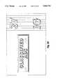
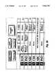
- FIGS. 11A-11Dshow the structure of a chassis in accordance with a preferred embodiment of the present invention for holding multimedia controllers (MMCs) and modulator cards constituting components of the system illustrated in FIG. 7.
- a rack 112 in FIG. 11Aholds switch 66 of FIG. 7 along with the MMCs and encoder and modulator cards 73a and 73b of FIG. 7.
- the MMCs and other cardsare mounted in rows 114 of the rack 112. Each row of cards is supported on a chassis 113 shown in FIG. 11D.
- the MMCs(called processor line cards in FIG. 11B and processors in FIG. 11D) are plugged into the left, rearward portion of the chassis 113, and the encoder and modulator cards are plugged into the right, forward portion of the chassis.
- the central vertical member 115 of the chassisprovides on both sides buses for digital and rf communication, as well as power for the cards that are mounted on either side of the chassis.
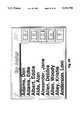
- the chassis 113is mounted in the rack 112 so that the processor line cards 67 face the reader in FIG. 11A. It can be seen, from the code letters in FIG. 11A for the card types listed in FIG. 11B, that a wide range of specialized MMCs may be employed to permit the system to provide a wide range of information services in a wide range of formats.
- MMCsmay be employed for movies only (A) (providing, for example, decompression of stored digitally compressed movies in MPEG format), for providing multimedia presentations using software utilizing the Intel 486 microprocessor (B) or the Intel Pentium microprocessor (C), or using 3DO or SGI formats (D and E).
- Digital MMCs(item (configured with corresponding modulator as suggested in item 82b of FIG. 8) (item F), as well as various communications cards including some with Live Sync (permitting interactive overlays on broadcast programming) (G) and permitting Home-v-Home communications (by which subscribers in two or more homes may communicate interactively, for example, in a computer game)(H) and gateway cards (I) are also provided.
- Live Sync and Home-v-Homeare trademarks of ICTV Inc., the assignee herein.
- FIG. 12illustrates the structure of an analog MMC 125 and a scrambler-modulator card 126 for the chassis of FIG. 11.
- the MMCincludes a video sub-system 121 and audio subsystem 122 operating under control of CPU 127 and control line 128 from the net manager 66a of FIG. 7.
- Line 128also is in communication with sources of information services, which receive decompression by block 121b and are mixed in the video effects and mixer module 121d.
- the module 121dalso receives input from graphics digital-to-analog converter 121c (providing, among other things, display for subscriber interaction) utilizing data from RAM/ROM storage 121a and control/content bitstream data obtained over line 128.
- graphics digital-to-analog converter 121cproviding, among other things, display for subscriber interaction
- TV tuner 129also provides video signals from conventional cable television channels over line 72a to the module 121d.
- the RGB/YUV output of the module 121dis provided to the scrambler-modulator card 126.
- the module 121dalso receives a composite sync signal input from scrambler/encoder 123 for use in providing a system timing reference to the video overlay.
- the audio sub-system 122 in FIG. 12has a coupling to TV tuner 129 (redrawn in this sub-system for convenience in reference) to provide audio signals from conventional cable television channels over line 72a to a mixer 122e, which also receives signals from background music source 122b, tactile response source 122c (for use in connection with the subscriber's remote control 14 in interactive television service), and digital program source 122d, which obtain control and content data over line 128.
- MTS stereo audio output of the mixer 122eis then provided to the modulator 24 of card 126.
- the scrambler-modulator card 126takes the RGB input from the video sub-system 121 and encryption control signal from CPU 127 to provide a scrambled video output to modulator 124.
- the audio output of the mixer 122e of the audio sub-system 122is fed directly to the modulator 124.
- the frequency of the carrier that is modulatedis determined by control of the net manager over line 128.
- the structure of digital MMC and modulator cards 141 and 142 shown in FIG. 14is similar to that of the analog cards in FIG. 12.
- the TV tuner and graphics digital-to-analog converter outputsare mixed as in FIG. 12. Instead of decompressing the digital video source before feeding it to the mixer module 121d, however, the compression here is maintained and sent directly to MPEG mixer 144a as MPEG source 2.
- the analog output of mixer 121dis compressed by compression encoder 144, which also receives the MTS audio output.
- the output of the compression encoderserves as source 1 input to MPEG mixer 144a. This MPEG output is then sent to encoder 143 and modulator 124.
- the MPEG mixing in block 144ais achieved by recognizing that the graphics overlay data from digital-to-analog converter 121c provides video content that does not change rapidly, and therefore can be implemented by causing the mixer to affect only the I-frame picture elements in the MPEG compression scheme with respect to the overlay content.
- MPEG's compression schemeis described in "C-Cube CL450 Development Kit User' s Guide,” dated Dec.
- the MPEG mixer 144includes an arrangement for providing the source 1 MPEG-encoded digital signal to a buffer; an arrangement for extracting from the source 2 digital signal I-frame picture elements to be overlayed; and an arrangement for overlaying the I-frame picture elements from the source 2 digital signal onto the corresponding regions of the I-pictures of the source 1 digital signal.
- the other picture types of the source 2 signalare not permitted by the mixer to modify portions of the I-picture that have resulted from the mixing.
- FIGS. 13A-13Cillustrate the structure of preferred embodiments of the audio subsystems for the MMCs of FIGS. 12 and 14.
- mixer 122eand, controlling its operation, a CPU 131, which may, but need not, be the same as CPU 127 of FIGS. 12 and 14.
- the CPU 131 of FIG. 13Ais operated in association with synthesizer 133.
- the content bitstreams on line 128may include digitally compressed audio that is decompressed by block 135.
- These embodimentsalso have an off-air tuner 132, which may, but need not, be the same as tuner 129 of FIGS. 12 and 14.
- digital-to-analog converter 134Other formats of digital audio, shown here coverted by digital-to-analog converter 134, are also within the scope of the use of these embodiments.
- synthesizer 133there may be provided a second decompression unit 135a (FIG. 13B), and similarly, in lieu of digital-to-analog converter 134, there may be provided a third decompression unit 135b.
- FIG. 15illustrates the structure of the data communications link at the headend (node) of the system of FIG. 7 with subscriber home interface controllers downstream.
- Outbound dataleave gateway 66b via line 153a where they go out over the interactive fiber trunk 42b.
- Inbound dataenter gateway 66b via line 155a from common return line 42c.
- the outbound dataleave from rf modulators 153 utilizing frequency shift key (FSK) encoding via encoders 152, and the inbound data enter via rf demodulators 155 using FSK detectors.
- Communications processing of the datais handled by communications processor 151 under control of compatible PC having microprocessor 156a, ROM 156b, and RAM 156c. The control may be managed additionally via network transceiver 157.
- FSKfrequency shift key
- the slotted ALOHA protocol used in a preferred embodiment for inbound and outbound data communicationsrequires that each home interface controller is assigned an address for data packets that are used in communication with the node.
- the net manager 66a of the nodeis signalled to that effect.
- the net manager 66aon determining that a given home interface controller is sought to be used for interactive television service (i.e., that the given home interface controller should be placed in an interactive mode), allocates additional data communication bandwidth for data communication with the particular home interface controller, so as to establish on a demand basis the data communications bandwidth utilized by the particular home interface controller.
- an appropriate MMCis assigned by the net manager 66a on a demand basis to the serve the subscriber's home interface controller while it is in the interactive mode.
- the home interface controllerwill have exclusive use of the assigned MMC, a "private line" to it over the data communications link and the interactive trunk 42b.
- several home interface controllersmay share the same time slot on a movie, for example, and these subscribers would have a "party line" to the MMC.
- appropriate MMCscan be used to provide overlays or other graphics on the television screen when the home interface controller is appropriately equipped.
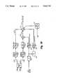
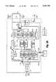
- FIG. 16illustrates the structure of the encoder/modulator 126 of FIG. 12. It includes a video processor 164 that has an RGB/YUV input and produces a scrambled NTSC video output on line 123d.
- the video processorhas inputs from sync genlock/scrambler timing block 163, including 3.58 MHz color subcarrier on line 163d, burst flag on line 163c, invert control on line 163b, and sandcastle pulses on line 163a.
- the sync genlock/scrambler timing block 163has inputs including genlock/free run select and encryption control 123c from CPU 127, and provides composite sync output on line 123a.
- the sync genlock/scrambler timing block 163also provides MTS subcarrier reference signal over line 123e to audio processor 162.
- the audio processor 162includes standard MTS stereo audio inputs for left, right, and secondary audio program.
- the scrambled NTSC video signal on line 123d together with the MTS composite audio output of audio processor 162are used to modulate a carrier at a desired frequency (established by the net manager 66a of FIGS. 6 and 7) by rf upconverter 161.
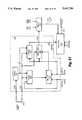
- FIG. 18illustrates the structure of the sync genlock/scrambler timing block 163 of FIG. 16. It is used to generate a series timing signals for both scrambling and overlay synchronization that are either genlocked to an external CATV signal or are otherwise inherently stable.
- the TV tuner 129 of FIG. 12additionally includes demodulator 186 in FIG. 18 and sync separator 185.
- the sync separatorincludes stripped horizontal sync output from conventional cable television video on line 181a and frame reset signal on line 182c.
- the stripped horizontal sync signal on line 181aforms a reference for phase-locking a 3.58 MHz oscillator in color subcarrier lock block 181, the output of which is furnished on line 163d.
- the signal on line 163dis divided down to provide a horizontal reference signal on line 182d.
- the signal on line 182dprovides a reference for phase locking the generation of sync signals by sync genlock block 182.
- This blockprovides composite sync and blanking signals on lines 182a and 182b, as well as frame sync, horizontal sync, burst flag, and MTS subcarrier reference on lines 184a, 184b, 163c, and 123e respectively.
- Block 182provides frame sync and horizontal sync signals to crypto logic block 184. It also provides composite sync and composite blanking signals to mode logic block 183.
- the crypto logic block 184 and mode logic block 183work in cooperation with one another to produce sandcastle pulses on line 163a in the manner described below in connection with FIG. 21.
- the sandcastle pulsesare used to provide scrambled NTSC video in the manner also described below in connection with FIG. 21.
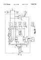
- FIG. 21illustrates an implementation of scrambling by crypto logic block 184 of FIG. 18 in cooperation with mode logic 183 and video processor 164.
- the scramblingis achieved by removing substantially all sync pulses from the NTSC signal. Infrequent (at least once per frame, two fields per frame) and randomly spaced horizontal pulses (sandcastles) are then reinserted.
- the effect of such scramblingis to deprive the standard NTSC receiver from obtaining horizontal and vertical sync lock with the incoming signal. This causes rapid horizontal and vertical roll of the picture.
- the scramblerclamps the video to a nearly white level. As a result when the video signal tends toward levels corresponding to black, the receiver frequently interprets this video content as a sync signal, with the further effect that the horizontal rolling and the vertical rolling are aperiodic.
- the sandcastlesare reinserted at a pseudorandom position in each consecutive frame, determined by vertical random number generator 212 in FIG. 21.
- the line counter 214is clocked by horizontal sync presented on line 184b, and is reset by frame sync pulses on line 184 each frame.
- the line counter 214stores a new number from the vertical random number generator 212 each time a frame reset pulse is received.
- line counter 214When line counter 214 has counted down to zero from the stored number, it triggers timing pulse generator 216 to send a pulse into mode logic control 183. Occasionally, on command from the load/count line 212a, the timing pulse generator 216 is caused to produce sandcastles in a plurality of successive lines.
- a command from the load/count line 212aalso triggers the loading from buffer register 211 of a previously stored seed value (loaded from line 211a) into both the vertical random number generator 212 and the horizontal random number generator 215.
- the seed value and load/count numbers over lines 211a and 212aare provided by CPU 127 of FIG. 12 on command of the net manager initially each time an MMC is assigned to serve a particular home interface controller and subsequently whenever the home interface controller reports over the data communications link that it has lost sync. Additionally the CPU 127 may be programmed to generate new seed values and load/count numbers in accordance with any desired strategy to resist efforts at rederiving sync without authorization.
- Each sandcastle pulselooks like the sum of the composite blanking and composite sync signals.
- the shape of the sandcastle pulseis therefore such that when summed in the summer 172 of FIG. 17 with sync suppressed video, the result is a signal that has a normal NTSC blanking period once per frame, and moreover, the normal blanking period occurs at pseudorandomly located lines in successive frames.
- the sandcastle pulsesappear on line 163a from mode logic controller 183.
- Composite sync signals 182a and composite blanking signals 182bare therefore summed and gated by the mode logic control 183 on receipt of pulses from the timing pulse generator 216 as described above.
- the width of the timing pulse generator signal over line 184c, which governs the duration of the sandcastle pulse,is equal to the horizontal blanking period.
- the horizontal random number generator 215issues a pulse at pseudorandom line intervals.
- Each pulsehas the duration of the active video portion of one horizontal line, and is fed over input 163b so as to cause the video processor 164 to produce entire horizontal lines having inverted video.
- FIG. 17illustrates the structure of the video processor 164 of FIGS. 16 and 21.
- Block 171shows a RGB/YUV to NTSC converter that is supplied with conventional inputs (including RGB/YUV, 3.58 MHz color subcarrier, and burst flag) but, in this case, lacking any sync or blanking input signals.
- the converted outputis standard NTSC with the exception that all sync information is suppressed.
- the inverter 173, under control of pulses present over line 163b,operates to invert the video on a random line-by-line basis in the manner described in connection with FIG. 21 above.
- the inverter outputis then summed in summer 172 with the sandcastle pulses to produce the scrambled NTSC waveform described above.
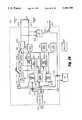
- FIG. 23illustrates the structure of a descrambler suitable for use in a home interface controller in accordance with a preferred embodiment of the present invention for descrambling a video signal that has been scrambled by a system in accordance with FIG. 21.
- the seed value and load/count numbers over lines 211a and 212aare provided by CPU 127 of FIG. 12 on command of the net manager initially each time an MMC is assigned to serve a particular home interface controller.
- the same seed valueis also provided to the particular home interface controller and is stored in the buffer register 231.
- Each time a new seed value is loaded into buffer register 211 of the scramblerthe same seed value is loaded into the buffer register 231 of the descrambler.
- the value in register 231remains in the register until clocked into the vertical and horizontal pseudorandom number generators 232 and 235 respectively by a pulse from the timing pulse detector 238.
- the relative timing of the seed data, and the load/count pulses, and the occurrence of sandcastles in the scrambled NTSC videoare shown as items 221, 222, and 223 of FIG. 22.
- Timing pulse detector 238monitors the incoming scrambled video over line 238a.
- the timing pulse detector 238produces a clocking pulse when it detects the plurality of pulses produced in the scrambled NTSC video when the scrambler in FIG. 21 received a load/count pulse over line 212a. (In this manner the timing pulse detector causes the generation a pulse at a time with respect to the received scrambled signal corresponding generally to the occurance of the load/count pulse when the original signal was being scrambled.)
- the timing pulse detector clocking pulsethen causes the stored seed value to be loaded into the pseudorandom number generators 232 and 235.
- the timing pulse generator 238also detects the occurance of single sandcastle pulses, and these are used to trigger the loading of the line counter 234 and the reset of the sync generator 237. This generator is phase-locked to the color burst and therefore produces the necessary sync signals to reconstruct a descrambled NTSC signal.
- the composite sync and composite blank signals from the generator 237feed sandcastle summer 2331 to produce a full series of sandcastles for every line and the entire NTSC frame structure.
- the output of summer 2331goes to sandcastle complement generator 233, which gates the input every time a sandcastle occurs on the scrambled video input line 238a.
- the output of the sandcastle complement generatoris therefore a stream of sandcastles that lacks a sandcastle at each time, and only at each time, a sandcastle is present in the scrambled video signal.
- This outputis fed to the decoder/amplifier 236, where it is summed with the scrambled video signal to produce an output that has a sandcastle at every line and is therefore a descrambled NTSC video signal.
- FIG. 19illustrates the structure of the audio processor section 162 of FIG. 16.
- Left and right audio inputs from audio sub-system 122are provided to the sum and difference matrix 191.
- the L+R sum output on line 191ais subjected to low-pass filter 1921 and pre-emphasis filter 1923.
- the L-R difference on line 191bis subjected to low-pass filter 1922 and dbx compressor 1924 and the compressor output is fed to a double balance mixer 193.
- MTS subcarrier reference signal on line 123eis subject to frequency division by divider 195, and further frequency division by halver 196.
- the output of the first divider 195is bandpass filtered by item 1971, and the resulting output is furnished to the double balanced mixer, so as to produce a double sideband suppressed carrier signal on line 193a.
- This signalis summed by summer 194 with the pre-emphasized L+R signal on line 1923a and the SAP subcarrier signal, the latter which is provided by SAP subcarrier generator 198, to which the SAP signal from audio sub-system 122 is supplied.
- FIG. 20illustrates the structure of the rf upconverter section 161 of FIG. 16.
- the inputsinclude BTSC audio on line 162aand scrambled NTSC video on line 123d.
- the video inputis provided to an a.m. modulator 2011 and the audio input is provided to an f.m. modulator 2012, and the respective modulator outputs are summed in summer 202.
- the output of the summeris bandpassed by filter 2031 and amplified by amplifier 2032.
- the amplifier outputis mixed with the signal from first local oscillator 2043, and the desired upper sideband is amplified and bandpass filtered by amplifier 2042 and filter 205.
- This intermediate frequency signalis then run through amplifier 2051 and mixed in mixer 2052 with a signal from a second local oscillator 2053 that is frequency agile (here a phase-locked oscillator).
- the outputis amplified (in amplifier 2053) and low-pass filtered by filter 2054, to eliminate the upper sideband, and the resulting signal is amplified by amplifier 2055 and provided as an output on line 161a. (This output is fed to combiner 73 of FIG. 7.)
- FIG. 24illustrates an alternative scrambling system.
- the systemhas an NTSC sync stripper 241 that supplies sync stripped video to a mixer 243, which masks sync signals by supplying a chroma subcarrier at all times, including during horizontal and vertical retrace.
- the luminance signalis caused to be present at all times.
- the composite sync signal output from stripper 241is provided with an encrypted value for the current phase shift caused by generator 2451.
- the encrypted valueis obtained from DES encoder 248, and this encrypted value, a digital signal, is placed on the signal during the vertical blanking interval as a binary pattern by vertical blanking interval data encoder 249.
- the composite sync signalis then subjected to an optional variable time delay by delay 2491 by a reference value that is also obtained from pseudo random generator 2451.
- a separate generatorcould be used, provided that the value obtained from such a generator is also encoded on the composite sync signal. This resultant scrambled composite sync signal is then provided as an output.
- This systemtherefore provides a continuously present chroma subcarrier, a continuously present luminance signal, and shifts the color burst by a random amount.
- the scrambled videois therefore relatively difficult to descramble, without access to the method of scrambling.
- FIG. 25shows a video descrambler system for descrambling the video scrambled in accordance with a system such as shown in FIG. 24.
- the scrambled video signal provided over line 259is gated off during both the vertical and the horizontal retrace intervals by gate 251, thereby removing the masking signals that interfere with proper sync, and the proper sync signal, presented on line 2543, is also added to mixer 253 to provide the composite video output over line 2532.
- the scrambled sync present at input 258is first used to provide the encrypted delay information (if an encrypted delay is used) which is decoded from the vertical blanking interval data by decoder 255 and deciphered by DES decoder 256.
- the scrambled sync signalis run through the programmable time delay 257 to provide a composite sync signal that is in phase with the video.
- Sync separator 254provides separate outputs for vertical and horizontal sync as well as a gate signal for the color burst.
- the vertical and horizontal sync signalsare run through NOR gate 2541 and OR gate 2542, so that 251 gates off the video during vertical and horizontal retrace except during color burst.
- Optional video decoder 252separates the chroma subcarrier (in the event that it is phase shifted), and the separated subcarrier is run through optional programmable phase delays 2531 in an amount specified by the decrypted .delay data to recover the original phase of the subcarrier.
- the resultant corrected subcarrieris mixed with the luminance and audio subcarrier and the composite sync signal by mixer 253 to provide a descrambled composite video signal over line 2532.
- FIG. 26illustrates the input and output structure of a home interface controller 13 in accordance with a preferred embodiment of the present invention.
- the controllerincludes input and output connections 261 for cable television rf, a video cassette recorder interface 262, an expansion interface 263 (for providing for baseband video; ports for printer, modem, and computer; and power line interface), infra-red transmitter port 264 for communication with conventional set top, video cassette recorder, and television, infra-red receiver port for communication with remote control 14, rf output 266 for communication with a television receiver, and baseband outputs 267 for communication with a television monitor.
- FIG. 27illustrates an embodiment of the controller of FIG. 26 suitable for analog television signal inputs.
- the rf cable television input 2711feeds diplex filter 271, the high pass section of which feeds television information signals and downstream data to line 2712 and splitter 2714 for division among VCR rf output at 2782, control data receiver 2751 and tuner 272.
- the low pass sectionreceives upstream data communications from control data transmitter 2752 over line 2713.
- Tuner 272is switched between VCR rf output 2782 and the television information signals from line 2712.
- the tuner's outputis fed to descrambler 373, which is bypassed by switch 2731.
- Genlock block 2732provides sync signals necessary for permitting overlay controller 2733 to function properly with the tuner output.
- the overlay controller's outputis fed directly to baseband video output 267a, and the tuner's audio output is routed through volume control 2741 to baseband audio output 267b.
- a channel 3/channel 4 modulator 274 coupled to these baseband outputsprovides rf output over line 266 to the subscriber television.
- Switch 2741switches the television between the home interface controller's television information signals and the VCR's rf output.
- Data communications involving the data receiver 2751 and the transmitter 2752is handled by data communications processor 275, and the information flow is via data bus 279 to and from set top processor 276, infra red interface 2761 for the remote control 14, overlay controller 2733, tuner 272, and volume control (setting) 2741.
- FIGS. 28 and 29illustrate embodiments of digital decompression and multimedia versions of the controller of FIG. 26.
- the embodiment of FIG. 28is similar to that of FIG. 27, except that there is also provided a high-speed data receiver 281 having an input connected to splitter 2714.
- the output of the high-speed receiverfeeds digital decompression module 282.
- This modulehas an audio output feeding mixer 283 along with the audio from tuner 272 and a video output that can be switched into the overlay controller 2733 by switch 285, the other position of which causes the overlay controller 2733 to obtain its video solely from the analog origin as before.
- the multimedia embodiment of FIG. 29represents a further enhancement of the embodiment of FIG. 28.
- a high-speed data transmitter 291These communicate with data bus 279 via high-speed data interface 292. Frequency control of communication at these data rates is assisted by frequency control block 2941.
- Audio mixer 295operates under control of sound microprocessor 2943. Additional effects are achieved by multimedia processor 2944, and overlay and effects block 2942.
- FIG. 30illustrates an alternative embodiment to the system of FIG. 7 in which the node 302 is disposed at a feeder 74a, typically proximate to abridger amplifier 74.
- abridger amplifiermay serve a plurality of feeders
- the nodemay similarly serve home information controllers on each of these feeders.
- main trunk 301 feedsexpress trunks 44.
- Bridger amplifiers 74are disposed at locations where the feeders 74a are connected to the trunks 44.
- At a tap 303is disposed drop 75 to a subscriber home having a home interface controller 13 and remote control 14.
- FIG. 31shows the bandwidth usage in a system in accordance with that of FIG. 30.
- the bandwidthis limited at the node 302 by a low pass filter so that digital carrier signals 319 at the bandwidth portion above the region 315 allocated to ordinary cable channels cannot reach the home interface controllers downstream of the node on the feeder 74a. (Alternatively, the bandwidth may be limited naturally by the bridger amplifier 74, with the node in communication with the trunk 44.)
- the removed digital signals in the bandwidth 319may typically carry compressed digital television information, and those of these signals that may be needed to serve downstream home interface controllers are obtained by the node 302 and remodulated to provide interactive television service downstream in the same spectrum 317 utilized upstream by the digital signals 319.
- Decompression of the digital signalsmay be accomplished either at the node 302 or at the home interface controllers 13.
- the node 302is able to utilize, uniquely for communication to the home interface controllers 13 associated with its own group of feeders 74a, the interactive channel bandwidth 317 shown in FIG. 31.
- Each nodemay utilize this bandwidth region independently of the other nodes, because signal transfer among nodes in the frequency spectrum portion 317 is small, and in any event can be controlled between different nodes.
- Inbound return data communicationsis achieved utilizing lower frequency band 316, with high pass filter at each node to prevent unwanted signal transfer; fresh remodulated carrers are introduced at the node for upstream communications.
- Guardbands 318are placed between bands 315 and 317 and between 316 and 315 to prevent interference.
- Each node 302then achieves utilization of those interactive television information signals pertinent to the subscribers associated with such node who have obtained access to such signals.
- FIG. 32shows the general architecture of outbound signal flow and two-way control in a system in accordance with the embodiment of FIG. 30.
- the node 302which may include an rf bus and tuners to demodulate television information signals (which may include conventional cable television signals as well as interactive television signals) from the headend.
- An MMC 53 with related modulator, as in the above embodiments,is placed in direct communication with a home interface controller 13 on a demand basis, so that the node 302 functions in essentially the same manner as does the node 77 when it is placed in the headend.
- FIGS. 33 and 34illustrate use of the channel menu system in accordance with a preferred embodiment of the invention.
- FIGS. 33 and 34show apparently different channels used for different information services, here TV listings (channel 31) and classified advertisements (channel 37), even though in the manner described previously, the frequency over which the home interface control unit receives information that has not changed.
- the term "different information service” as used in this description and in the claims followingcan mean any information service in a mode appearing to be different to the subscriber, including an interactive service in a different information area, or a different interactive service, or a different television broadcast signal provided by the headend, etc.
- FIGS. 35-41illustrate use of the carousel menu system and of the manner in which the invention in a preferred embodiment provides interaction with the user.
- FIG. 35illustrates an embodiment of the carousel menu system in accordance with the invention when an interactive information service has been selected. (In this case, the interactive service is classified advertisements.)
- the carouselhere shows three faces, one of which is a frontal face. The frontal face shows one or more menu choices. The two side faces shown are greeked, so as to display the apparent availability of other choices if the carousel is caused to rotate so that one of the side faces is moved to the frontal position.
- the overlay 2733described in connection with FIGS. 27-29, or the video effects and mixer block 121d of FIGS.
- a cursorcan be moved over the television display by the remote unit 14, and when the cursor overlays the menu choice of interest, the choice may be selected by pushing the appropriate button on the remote unit 14.
- the carouselis momentarily shown to be apparently rotated in one direction or another, and thereafter another set of choices is caused to appear on the frontal face, the flanking side faces again being greeked.
- FIGS. 36 through 41illustrate how interactive television service may be provided in accordance with a preferred embodiment of the invention. If TV listings (here channel 31) has been selected, there is displayed a grid portion, which can be shifted on screen for viewing the grid in the entirety. Shown in FIG. 36 is a portion of the grid display, plotting television programs as a function of channel and time for a given date and portion of the day; and the date and portion of the day can be selected by the subscriber.
- TV listingshere channel 31
- FIG. 36Shown in FIG. 36 is a portion of the grid display, plotting television programs as a function of channel and time for a given date and portion of the day; and the date and portion of the day can be selected by the subscriber.
- the "Smart TV” selectionpermits the subscriber to search for programs or other information service offerings in the manner illustrated in subsequent figures.
- the carousel choices indicated in FIG. 37permit the subscriber to find programs and movies by subject, by show, or by actor. Other choices permit the subscriber to program his favorite channels and find offerings on those channels, or to identify offerings on a pay per view basis, or to return to the grid of FIG. 36. If the "by actor" selection is made, the alphabetical menu of FIG. 38 is presented. To find listings for "Bogart", the top button “ABCDE” would be selected, producing the display of FIG. 39.
Landscapes
- Engineering & Computer Science (AREA)
- Multimedia (AREA)
- Signal Processing (AREA)
- Theoretical Computer Science (AREA)
- General Engineering & Computer Science (AREA)
- Human Computer Interaction (AREA)
- Physics & Mathematics (AREA)
- General Physics & Mathematics (AREA)
- Two-Way Televisions, Distribution Of Moving Picture Or The Like (AREA)
Abstract
Description
Claims (4)
Priority Applications (1)
| Application Number | Priority Date | Filing Date | Title |
|---|---|---|---|
| US08/310,719US5442700A (en) | 1990-09-28 | 1994-09-22 | Scrambling method |
Applications Claiming Priority (5)
| Application Number | Priority Date | Filing Date | Title |
|---|---|---|---|
| US07/589,205US5093718A (en) | 1990-09-28 | 1990-09-28 | Interactive home information system |
| US07/754,932US5220420A (en) | 1990-09-28 | 1991-09-10 | Interactive home information system for distributing compressed television programming |
| US07/877,325US5412720A (en) | 1990-09-28 | 1992-05-01 | Interactive home information system |
| US08/056,958US5526034A (en) | 1990-09-28 | 1993-05-03 | Interactive home information system with signal assignment |
| US08/310,719US5442700A (en) | 1990-09-28 | 1994-09-22 | Scrambling method |
Related Parent Applications (1)
| Application Number | Title | Priority Date | Filing Date |
|---|---|---|---|
| US08/056,958DivisionUS5526034A (en) | 1990-09-28 | 1993-05-03 | Interactive home information system with signal assignment |
Publications (1)
| Publication Number | Publication Date |
|---|---|
| US5442700Atrue US5442700A (en) | 1995-08-15 |
Family
ID=27416538
Family Applications (1)
| Application Number | Title | Priority Date | Filing Date |
|---|---|---|---|
| US08/310,719Expired - LifetimeUS5442700A (en) | 1990-09-28 | 1994-09-22 | Scrambling method |
Country Status (1)
| Country | Link |
|---|---|
| US (1) | US5442700A (en) |
Cited By (79)
| Publication number | Priority date | Publication date | Assignee | Title |
|---|---|---|---|---|
| US5517232A (en)* | 1993-07-10 | 1996-05-14 | Alcatel Sel Aktiengesellschaft | Cable television distribution network with video-on-demand transmission |
| US5631693A (en)* | 1993-10-25 | 1997-05-20 | Antec Corporation | Method and apparatus for providing on demand services in a subscriber system |
| US5671217A (en)* | 1995-12-14 | 1997-09-23 | Time Warner Entertainment Co. L.P. | Scalable communications network employing shared logical nodes |
| US5729279A (en)* | 1995-01-26 | 1998-03-17 | Spectravision, Inc. | Video distribution system |
| US5745837A (en)* | 1995-08-25 | 1998-04-28 | Terayon Corporation | Apparatus and method for digital data transmission over a CATV system using an ATM transport protocol and SCDMA |
| US5771435A (en)* | 1995-12-14 | 1998-06-23 | Time Warner Entertainment Co. L.P. | Method and apparatus for processing requests for video presentations of interactive applications in which VOD functionality is provided during NVOD presentations |
| US5774458A (en)* | 1995-12-14 | 1998-06-30 | Time Warner Cable | Multiplex amplifiers for two-way communications in a full-service network |
| US5793759A (en)* | 1995-08-25 | 1998-08-11 | Terayon Corporation | Apparatus and method for digital data transmission over video cable using orthogonal cyclic codes |
| US5797010A (en)* | 1995-12-22 | 1998-08-18 | Time Warner Cable | Multiple run-time execution environment support in a set-top processor |
| US5802448A (en)* | 1995-12-14 | 1998-09-01 | Time Warner Entertainment Co., L.P. | Method and apparatus for processing requests for interactive applications based on system resources |
| US5805583A (en)* | 1995-08-25 | 1998-09-08 | Terayon Communication Systems | Process for communicating multiple channels of digital data in distributed systems using synchronous code division multiple access |
| US5805154A (en)* | 1995-12-14 | 1998-09-08 | Time Warner Entertainment Co. L.P. | Integrated broadcast application with broadcast portion having option display for access to on demand portion |
| US5818840A (en)* | 1995-12-14 | 1998-10-06 | Time Warner Entertainment Co. L.P. | Asymmetric ATM switch |
| US5819036A (en)* | 1995-12-14 | 1998-10-06 | Time Warner Cable | Method for message addressing in a full service network |
| US5822530A (en)* | 1995-12-14 | 1998-10-13 | Time Warner Entertainment Co. L.P. | Method and apparatus for processing requests for video on demand versions of interactive applications |
| US5822676A (en)* | 1995-12-14 | 1998-10-13 | Time Warner Entertainment Co. L.P. | Digital serialization of program events |
| US5966376A (en)* | 1995-08-25 | 1999-10-12 | Terayon Communication Systems, Inc. | Apparatus and method for digital data transmission using orthogonal cyclic codes |
| US5982446A (en)* | 1995-10-18 | 1999-11-09 | Mitel Semiconductor | Video modulator arrangement |
| US5991308A (en)* | 1995-08-25 | 1999-11-23 | Terayon Communication Systems, Inc. | Lower overhead method for data transmission using ATM and SCDMA over hybrid fiber coax cable plant |
| US5995134A (en)* | 1995-12-14 | 1999-11-30 | Time Warner Cable | Method and apparatus for enticing a passive television viewer by automatically playing promotional presentations of selectable options in response to the viewer's inactivity |
| US6044396A (en)* | 1995-12-14 | 2000-03-28 | Time Warner Cable, A Division Of Time Warner Entertainment Company, L.P. | Method and apparatus for utilizing the available bit rate in a constrained variable bit rate channel |
| US6055315A (en)* | 1997-12-09 | 2000-04-25 | Ictv, Inc. | Distributed scrambling method and system |
| US6282310B1 (en)* | 1994-06-20 | 2001-08-28 | Canon Kabushiki Kaisha | Image processing apparatus, method, and image processing system |
| US6307868B1 (en) | 1995-08-25 | 2001-10-23 | Terayon Communication Systems, Inc. | Apparatus and method for SCDMA digital data transmission using orthogonal codes and a head end modem with no tracking loops |
| US6340987B1 (en) | 1995-12-14 | 2002-01-22 | Time Warner Entertainment Company L.P. | Method and apparatus for masking latency in an interactive television network |
| US6356555B1 (en) | 1995-08-25 | 2002-03-12 | Terayon Communications Systems, Inc. | Apparatus and method for digital data transmission using orthogonal codes |
| US20020031224A1 (en)* | 1998-09-08 | 2002-03-14 | On Command Corporation | Secure multimedia communications system |
| US6665308B1 (en) | 1995-08-25 | 2003-12-16 | Terayon Communication Systems, Inc. | Apparatus and method for equalization in distributed digital data transmission systems |
| JP2004501579A (en)* | 2000-06-19 | 2004-01-15 | オン コマンド コーポレーション | Secure multimedia communication system |
| US20040045022A1 (en)* | 2002-09-03 | 2004-03-04 | Steven Riedl | Digital message insertion technique for analog video services |
| US20040163124A1 (en)* | 1998-09-08 | 2004-08-19 | Ganesh Basawapatna | Enhanced security communications system |
| US20050114906A1 (en)* | 1993-05-03 | 2005-05-26 | Ictv, Inc. | System for interactive television |
| US6967966B1 (en) | 1999-11-03 | 2005-11-22 | Adc Telecommunications, Inc. | Digital return path for hybrid fiber/coax network |
| US7016308B1 (en) | 1999-03-19 | 2006-03-21 | Broadband Royalty Corporation | Digital return path for hybrid fiber/coax network |
| US7031335B1 (en)* | 1999-11-03 | 2006-04-18 | Adc Telecommunications, Inc. | Digital node for hybrid fiber/coax network |
| US20060294566A1 (en)* | 2003-09-17 | 2006-12-28 | Wayne Zlattner | Method and apparatus for automatically altering viewed segments of television broadcast |
| US20070011717A1 (en)* | 2005-07-06 | 2007-01-11 | Lauder Gary M | Distribution of interactive information content within a plurality of disparate distribution networks |
| US20070028288A1 (en)* | 2005-07-26 | 2007-02-01 | Sigmon Robert B Jr | System and method for providing video content associated with a source image to a television in a communication network |
| US20070028278A1 (en)* | 2005-07-27 | 2007-02-01 | Sigmon Robert B Jr | System and method for providing pre-encoded audio content to a television in a communications network |
| US20070162945A1 (en)* | 2006-01-10 | 2007-07-12 | Mills Brendon W | System and method for routing content |
| US20070299920A1 (en)* | 2006-06-27 | 2007-12-27 | Crespo Arturo E | Anonymous Email Address Management |
| US20080091845A1 (en)* | 2006-10-13 | 2008-04-17 | Mills Brendon W | System and method for processing content |
| US20080201736A1 (en)* | 2007-01-12 | 2008-08-21 | Ictv, Inc. | Using Triggers with Video for Interactive Content Identification |
| USRE40564E1 (en) | 1992-09-17 | 2008-11-04 | Adc Telecommunications, Inc. | Cellular communications system with sectorization |
| US20090119322A1 (en)* | 2007-11-07 | 2009-05-07 | Mills Brendon W | System and method for managing content |
| US7599711B2 (en) | 2006-04-12 | 2009-10-06 | Adc Telecommunications, Inc. | Systems and methods for analog transport of RF voice/data communications |
| US20090328109A1 (en)* | 2007-01-12 | 2009-12-31 | Activevideo Networks, Inc. | Providing Television Broadcasts over a Managed Network and Interactive Content over an Unmanaged Network to a Client Device |
| US20100070608A1 (en)* | 2008-09-10 | 2010-03-18 | Ripcode, Inc. | System and method for delivering content |
| US20100094931A1 (en)* | 2008-10-14 | 2010-04-15 | Ripcode, Inc. | System and method for progressive delivery of media content |
| US7962111B2 (en) | 2002-02-25 | 2011-06-14 | ADC Wireless, Inc. | Distributed automatic gain control system |
| US7984474B2 (en) | 2000-02-08 | 2011-07-19 | Quartics, Inc. | Method and apparatus for a digitized CATV network for bundled services |
| US20110179106A1 (en)* | 2010-01-15 | 2011-07-21 | Ibahn General Holdings Corporation | Virtual user interface |
| US20110261889A1 (en)* | 2010-04-27 | 2011-10-27 | Comcast Cable Communications, Llc | Remote User Interface |
| US8583100B2 (en) | 2007-01-25 | 2013-11-12 | Adc Telecommunications, Inc. | Distributed remote base station system |
| US8627509B2 (en) | 2007-07-02 | 2014-01-07 | Rgb Networks, Inc. | System and method for monitoring content |
| US8737454B2 (en) | 2007-01-25 | 2014-05-27 | Adc Telecommunications, Inc. | Modular wireless communications platform |
| US8836749B2 (en) | 1993-03-12 | 2014-09-16 | Telebuyer, Llc | Security monitoring system with combined video and graphics display |
| US8958789B2 (en) | 2002-12-03 | 2015-02-17 | Adc Telecommunications, Inc. | Distributed digital antenna system |
| US9003455B2 (en) | 2010-07-30 | 2015-04-07 | Guest Tek Interactive Entertainment Ltd. | Hospitality media system employing virtual set top boxes |
| US9001811B2 (en) | 2009-05-19 | 2015-04-07 | Adc Telecommunications, Inc. | Method of inserting CDMA beacon pilots in output of distributed remote antenna nodes |
| US9021541B2 (en) | 2010-10-14 | 2015-04-28 | Activevideo Networks, Inc. | Streaming digital video between video devices using a cable television system |
| US9042454B2 (en) | 2007-01-12 | 2015-05-26 | Activevideo Networks, Inc. | Interactive encoded content system including object models for viewing on a remote device |
| US9123084B2 (en) | 2012-04-12 | 2015-09-01 | Activevideo Networks, Inc. | Graphical application integration with MPEG objects |
| US9204203B2 (en) | 2011-04-07 | 2015-12-01 | Activevideo Networks, Inc. | Reduction of latency in video distribution networks using adaptive bit rates |
| US9219922B2 (en) | 2013-06-06 | 2015-12-22 | Activevideo Networks, Inc. | System and method for exploiting scene graph information in construction of an encoded video sequence |
| US9282131B2 (en) | 2009-01-20 | 2016-03-08 | Imagine Communications Corp. | System and method for splicing media files |
| US9294785B2 (en) | 2013-06-06 | 2016-03-22 | Activevideo Networks, Inc. | System and method for exploiting scene graph information in construction of an encoded video sequence |
| US9326047B2 (en) | 2013-06-06 | 2016-04-26 | Activevideo Networks, Inc. | Overlay rendering of user interface onto source video |
| US9577922B2 (en) | 2014-02-18 | 2017-02-21 | Commscope Technologies Llc | Selectively combining uplink signals in distributed antenna systems |
| US9788029B2 (en) | 2014-04-25 | 2017-10-10 | Activevideo Networks, Inc. | Intelligent multiplexing using class-based, multi-dimensioned decision logic for managed networks |
| US9800939B2 (en) | 2009-04-16 | 2017-10-24 | Guest Tek Interactive Entertainment Ltd. | Virtual desktop services with available applications customized according to user type |
| US9800945B2 (en) | 2012-04-03 | 2017-10-24 | Activevideo Networks, Inc. | Class-based intelligent multiplexing over unmanaged networks |
| US9826197B2 (en) | 2007-01-12 | 2017-11-21 | Activevideo Networks, Inc. | Providing television broadcasts over a managed network and interactive content over an unmanaged network to a client device |
| US10275128B2 (en) | 2013-03-15 | 2019-04-30 | Activevideo Networks, Inc. | Multiple-mode system and method for providing user selectable video content |
| US10409445B2 (en) | 2012-01-09 | 2019-09-10 | Activevideo Networks, Inc. | Rendering of an interactive lean-backward user interface on a television |
| US10499269B2 (en) | 2015-11-12 | 2019-12-03 | Commscope Technologies Llc | Systems and methods for assigning controlled nodes to channel interfaces of a controller |
| US10498434B2 (en) | 2000-07-19 | 2019-12-03 | CommScope Technolgies LLC | Point-to-multipoint digital radio frequency transport |
| US11056009B2 (en) | 2018-01-31 | 2021-07-06 | Performance Drone Works Llc | Secure control and operation of drones |
| USD1088038S1 (en)* | 2022-10-17 | 2025-08-12 | Yokogawa Electric Corporation | Display screen or portion thereof with icon |
Citations (16)
| Publication number | Priority date | Publication date | Assignee | Title |
|---|---|---|---|---|
| CA682776A (en)* | 1964-03-24 | Zenith Radio Corporation | Subscription television system | |
| US4081831A (en)* | 1976-04-08 | 1978-03-28 | Twin County Trans-Video, Inc. | High security subscription television system employing real time control of subscriber's program reception |
| US4222068A (en)* | 1978-11-02 | 1980-09-09 | American Television And Communications Corporation | Subscription television apparatus and methods |
| US4253114A (en)* | 1976-04-08 | 1981-02-24 | Twin County Trans-Video Inc. | High security subscription television system employing real time control of subscriber's program reception |
| US4408225A (en)* | 1981-07-06 | 1983-10-04 | Zenith Radio Corporation | Subscription television decoder |
| US4466017A (en)* | 1981-12-23 | 1984-08-14 | Scientific-Atlanta, Inc. | Sync suppression scrambling of television signals for subscription TV |
| US4471380A (en)* | 1982-03-15 | 1984-09-11 | Scientific-Atlanta, Inc. | Scrambling and descrambling of television signals for subscription TV |
| EP0128771A2 (en)* | 1983-06-10 | 1984-12-19 | General Instrument Corporation | Timing generator for sync suppressed television signals |
| US4523228A (en)* | 1983-02-15 | 1985-06-11 | Scientific Atlanta Inc. | Sync suppression scrambling of television signals for subscription TV |
| US4554581A (en)* | 1982-12-20 | 1985-11-19 | Zenith Radio Corporation | STV Decoder with improved data signal recognition capability |
| US4567517A (en)* | 1983-02-15 | 1986-01-28 | Scientific-Atlanta, Inc. | Descrambler for sync-suppressed TV signals |
| US4614970A (en)* | 1983-12-13 | 1986-09-30 | U.S. Computer Systems | Descrambler apparatus |
| US4922532A (en)* | 1988-07-29 | 1990-05-01 | Scientific-Atlanta, Inc. | Sync suppression scrambling and descrambling of television signals for subscription TV |
| US5008934A (en)* | 1988-10-18 | 1991-04-16 | Pioneer Electronic Corporation | CATV transmission system using scrambled signals |
| EP0449633A1 (en)* | 1990-03-30 | 1991-10-02 | Matsushita Electric Industrial Co., Ltd. | Pay television |
| US5060262A (en)* | 1990-05-07 | 1991-10-22 | Bevins Jr George L | Video scrambling, audio masking and data transmission methods for wireless cable systems |
- 1994
- 1994-09-22USUS08/310,719patent/US5442700A/ennot_activeExpired - Lifetime
Patent Citations (16)
| Publication number | Priority date | Publication date | Assignee | Title |
|---|---|---|---|---|
| CA682776A (en)* | 1964-03-24 | Zenith Radio Corporation | Subscription television system | |
| US4081831A (en)* | 1976-04-08 | 1978-03-28 | Twin County Trans-Video, Inc. | High security subscription television system employing real time control of subscriber's program reception |
| US4253114A (en)* | 1976-04-08 | 1981-02-24 | Twin County Trans-Video Inc. | High security subscription television system employing real time control of subscriber's program reception |
| US4222068A (en)* | 1978-11-02 | 1980-09-09 | American Television And Communications Corporation | Subscription television apparatus and methods |
| US4408225A (en)* | 1981-07-06 | 1983-10-04 | Zenith Radio Corporation | Subscription television decoder |
| US4466017A (en)* | 1981-12-23 | 1984-08-14 | Scientific-Atlanta, Inc. | Sync suppression scrambling of television signals for subscription TV |
| US4471380A (en)* | 1982-03-15 | 1984-09-11 | Scientific-Atlanta, Inc. | Scrambling and descrambling of television signals for subscription TV |
| US4554581A (en)* | 1982-12-20 | 1985-11-19 | Zenith Radio Corporation | STV Decoder with improved data signal recognition capability |
| US4523228A (en)* | 1983-02-15 | 1985-06-11 | Scientific Atlanta Inc. | Sync suppression scrambling of television signals for subscription TV |
| US4567517A (en)* | 1983-02-15 | 1986-01-28 | Scientific-Atlanta, Inc. | Descrambler for sync-suppressed TV signals |
| EP0128771A2 (en)* | 1983-06-10 | 1984-12-19 | General Instrument Corporation | Timing generator for sync suppressed television signals |
| US4614970A (en)* | 1983-12-13 | 1986-09-30 | U.S. Computer Systems | Descrambler apparatus |
| US4922532A (en)* | 1988-07-29 | 1990-05-01 | Scientific-Atlanta, Inc. | Sync suppression scrambling and descrambling of television signals for subscription TV |
| US5008934A (en)* | 1988-10-18 | 1991-04-16 | Pioneer Electronic Corporation | CATV transmission system using scrambled signals |
| EP0449633A1 (en)* | 1990-03-30 | 1991-10-02 | Matsushita Electric Industrial Co., Ltd. | Pay television |
| US5060262A (en)* | 1990-05-07 | 1991-10-22 | Bevins Jr George L | Video scrambling, audio masking and data transmission methods for wireless cable systems |
Non-Patent Citations (2)
| Title |
|---|
| "An Encoder/Decpder Chip Set for the MPEG Video Standard", Ichiro Tamitani et al., 1991 IEEE International Conference on Acoustics, Speech and Signal Processing, vol. 5, San Francisco, Calif. |
| An Encoder/Decpder Chip Set for the MPEG Video Standard , Ichiro Tamitani et al., 1991 IEEE International Conference on Acoustics, Speech and Signal Processing, vol. 5, San Francisco, Calif.* |
Cited By (122)
| Publication number | Priority date | Publication date | Assignee | Title |
|---|---|---|---|---|
| USRE45321E1 (en) | 1992-09-17 | 2015-01-06 | Adc Telecommunications, Inc. | Cellular communications system with sectorization |
| USRE40564E1 (en) | 1992-09-17 | 2008-11-04 | Adc Telecommunications, Inc. | Cellular communications system with sectorization |
| USRE43964E1 (en) | 1992-09-17 | 2013-02-05 | Adc Telecommunications, Inc. | Cellular communications system with sectorization |
| US9053485B2 (en) | 1993-03-12 | 2015-06-09 | Telebuyer, Llc | Security monitoring system with image comparison of monitored location |
| US8842151B2 (en) | 1993-03-12 | 2014-09-23 | Telebuyer, Llc | Security monitoring system with flexible monitoring sequence |
| US8836749B2 (en) | 1993-03-12 | 2014-09-16 | Telebuyer, Llc | Security monitoring system with combined video and graphics display |
| US20050114906A1 (en)* | 1993-05-03 | 2005-05-26 | Ictv, Inc. | System for interactive television |
| US5517232A (en)* | 1993-07-10 | 1996-05-14 | Alcatel Sel Aktiengesellschaft | Cable television distribution network with video-on-demand transmission |
| US5631693A (en)* | 1993-10-25 | 1997-05-20 | Antec Corporation | Method and apparatus for providing on demand services in a subscriber system |
| US6282310B1 (en)* | 1994-06-20 | 2001-08-28 | Canon Kabushiki Kaisha | Image processing apparatus, method, and image processing system |
| US5818512A (en)* | 1995-01-26 | 1998-10-06 | Spectravision, Inc. | Video distribution system |
| US5729279A (en)* | 1995-01-26 | 1998-03-17 | Spectravision, Inc. | Video distribution system |
| US5767894A (en)* | 1995-01-26 | 1998-06-16 | Spectradyne, Inc. | Video distribution system |
| US7031344B2 (en) | 1995-08-25 | 2006-04-18 | Terayon Communication Systems, Inc. | Apparatus and method for SCDMA digital data transmission using orthogonal codes and a head end modem with no tracking loops |
| US5991308A (en)* | 1995-08-25 | 1999-11-23 | Terayon Communication Systems, Inc. | Lower overhead method for data transmission using ATM and SCDMA over hybrid fiber coax cable plant |
| US7239650B2 (en) | 1995-08-25 | 2007-07-03 | Terayon Communication Systems, Inc. | Apparatus and method for receiving upstream data transmissions from multiple remote transmitters |
| US7095707B2 (en) | 1995-08-25 | 2006-08-22 | Terayon Communication Systems, Inc. | Apparatus and method for trellis encoding data for transmission in digital data transmission systems |
| US5793759A (en)* | 1995-08-25 | 1998-08-11 | Terayon Corporation | Apparatus and method for digital data transmission over video cable using orthogonal cyclic codes |
| US5966376A (en)* | 1995-08-25 | 1999-10-12 | Terayon Communication Systems, Inc. | Apparatus and method for digital data transmission using orthogonal cyclic codes |
| US7020165B2 (en) | 1995-08-25 | 2006-03-28 | Terayon Communication Systems, Inc | Apparatus and method for trellis encoding data for transmission in digital data transmission systems |
| US5745837A (en)* | 1995-08-25 | 1998-04-28 | Terayon Corporation | Apparatus and method for digital data transmission over a CATV system using an ATM transport protocol and SCDMA |
| US6937617B2 (en) | 1995-08-25 | 2005-08-30 | Terayon Communication System, Inc. | Apparatus and method for trellis encoding data for transmission in digital data transmission systems |
| US6356555B1 (en) | 1995-08-25 | 2002-03-12 | Terayon Communications Systems, Inc. | Apparatus and method for digital data transmission using orthogonal codes |
| US6665308B1 (en) | 1995-08-25 | 2003-12-16 | Terayon Communication Systems, Inc. | Apparatus and method for equalization in distributed digital data transmission systems |
| US6154456A (en)* | 1995-08-25 | 2000-11-28 | Terayon Communication Systems, Inc. | Apparatus and method for digital data transmission using orthogonal codes |
| US5805583A (en)* | 1995-08-25 | 1998-09-08 | Terayon Communication Systems | Process for communicating multiple channels of digital data in distributed systems using synchronous code division multiple access |
| US6307868B1 (en) | 1995-08-25 | 2001-10-23 | Terayon Communication Systems, Inc. | Apparatus and method for SCDMA digital data transmission using orthogonal codes and a head end modem with no tracking loops |
| US5982446A (en)* | 1995-10-18 | 1999-11-09 | Mitel Semiconductor | Video modulator arrangement |
| US5822676A (en)* | 1995-12-14 | 1998-10-13 | Time Warner Entertainment Co. L.P. | Digital serialization of program events |
| US6340987B1 (en) | 1995-12-14 | 2002-01-22 | Time Warner Entertainment Company L.P. | Method and apparatus for masking latency in an interactive television network |
| US5671217A (en)* | 1995-12-14 | 1997-09-23 | Time Warner Entertainment Co. L.P. | Scalable communications network employing shared logical nodes |
| US5802448A (en)* | 1995-12-14 | 1998-09-01 | Time Warner Entertainment Co., L.P. | Method and apparatus for processing requests for interactive applications based on system resources |
| US5771435A (en)* | 1995-12-14 | 1998-06-23 | Time Warner Entertainment Co. L.P. | Method and apparatus for processing requests for video presentations of interactive applications in which VOD functionality is provided during NVOD presentations |
| US5822530A (en)* | 1995-12-14 | 1998-10-13 | Time Warner Entertainment Co. L.P. | Method and apparatus for processing requests for video on demand versions of interactive applications |
| US5819036A (en)* | 1995-12-14 | 1998-10-06 | Time Warner Cable | Method for message addressing in a full service network |
| US5805154A (en)* | 1995-12-14 | 1998-09-08 | Time Warner Entertainment Co. L.P. | Integrated broadcast application with broadcast portion having option display for access to on demand portion |
| US5774458A (en)* | 1995-12-14 | 1998-06-30 | Time Warner Cable | Multiplex amplifiers for two-way communications in a full-service network |
| US5995134A (en)* | 1995-12-14 | 1999-11-30 | Time Warner Cable | Method and apparatus for enticing a passive television viewer by automatically playing promotional presentations of selectable options in response to the viewer's inactivity |
| US6044396A (en)* | 1995-12-14 | 2000-03-28 | Time Warner Cable, A Division Of Time Warner Entertainment Company, L.P. | Method and apparatus for utilizing the available bit rate in a constrained variable bit rate channel |
| US5818840A (en)* | 1995-12-14 | 1998-10-06 | Time Warner Entertainment Co. L.P. | Asymmetric ATM switch |
| US5797010A (en)* | 1995-12-22 | 1998-08-18 | Time Warner Cable | Multiple run-time execution environment support in a set-top processor |
| US6055315A (en)* | 1997-12-09 | 2000-04-25 | Ictv, Inc. | Distributed scrambling method and system |
| US20020031224A1 (en)* | 1998-09-08 | 2002-03-14 | On Command Corporation | Secure multimedia communications system |
| US20040163124A1 (en)* | 1998-09-08 | 2004-08-19 | Ganesh Basawapatna | Enhanced security communications system |
| US7016308B1 (en) | 1999-03-19 | 2006-03-21 | Broadband Royalty Corporation | Digital return path for hybrid fiber/coax network |
| US6967966B1 (en) | 1999-11-03 | 2005-11-22 | Adc Telecommunications, Inc. | Digital return path for hybrid fiber/coax network |
| US7031335B1 (en)* | 1999-11-03 | 2006-04-18 | Adc Telecommunications, Inc. | Digital node for hybrid fiber/coax network |
| US7984474B2 (en) | 2000-02-08 | 2011-07-19 | Quartics, Inc. | Method and apparatus for a digitized CATV network for bundled services |
| JP2004501579A (en)* | 2000-06-19 | 2004-01-15 | オン コマンド コーポレーション | Secure multimedia communication system |
| US10505635B2 (en) | 2000-07-19 | 2019-12-10 | Commscope Technologies Llc | Point-to-multipoint digital radio frequency transport |
| US10498434B2 (en) | 2000-07-19 | 2019-12-03 | CommScope Technolgies LLC | Point-to-multipoint digital radio frequency transport |
| US7962111B2 (en) | 2002-02-25 | 2011-06-14 | ADC Wireless, Inc. | Distributed automatic gain control system |
| US20040045022A1 (en)* | 2002-09-03 | 2004-03-04 | Steven Riedl | Digital message insertion technique for analog video services |
| US8958789B2 (en) | 2002-12-03 | 2015-02-17 | Adc Telecommunications, Inc. | Distributed digital antenna system |
| USRE50112E1 (en) | 2002-12-03 | 2024-09-03 | Outdoor Wireless Networks LLC | Distributed digital antenna system |
| USRE49377E1 (en) | 2002-12-03 | 2023-01-17 | Commscope Technologies Llc | Distributed digital antenna system |
| US20060294566A1 (en)* | 2003-09-17 | 2006-12-28 | Wayne Zlattner | Method and apparatus for automatically altering viewed segments of television broadcast |
| US20070011717A1 (en)* | 2005-07-06 | 2007-01-11 | Lauder Gary M | Distribution of interactive information content within a plurality of disparate distribution networks |
| US9077860B2 (en) | 2005-07-26 | 2015-07-07 | Activevideo Networks, Inc. | System and method for providing video content associated with a source image to a television in a communication network |
| US8074248B2 (en) | 2005-07-26 | 2011-12-06 | Activevideo Networks, Inc. | System and method for providing video content associated with a source image to a television in a communication network |
| US20070028288A1 (en)* | 2005-07-26 | 2007-02-01 | Sigmon Robert B Jr | System and method for providing video content associated with a source image to a television in a communication network |
| US20070028278A1 (en)* | 2005-07-27 | 2007-02-01 | Sigmon Robert B Jr | System and method for providing pre-encoded audio content to a television in a communications network |
| US9294728B2 (en) | 2006-01-10 | 2016-03-22 | Imagine Communications Corp. | System and method for routing content |
| US20070162945A1 (en)* | 2006-01-10 | 2007-07-12 | Mills Brendon W | System and method for routing content |
| US7599711B2 (en) | 2006-04-12 | 2009-10-06 | Adc Telecommunications, Inc. | Systems and methods for analog transport of RF voice/data communications |
| US20070299920A1 (en)* | 2006-06-27 | 2007-12-27 | Crespo Arturo E | Anonymous Email Address Management |
| US8180920B2 (en) | 2006-10-13 | 2012-05-15 | Rgb Networks, Inc. | System and method for processing content |
| US20080091845A1 (en)* | 2006-10-13 | 2008-04-17 | Mills Brendon W | System and method for processing content |
| US9826197B2 (en) | 2007-01-12 | 2017-11-21 | Activevideo Networks, Inc. | Providing television broadcasts over a managed network and interactive content over an unmanaged network to a client device |
| US9355681B2 (en) | 2007-01-12 | 2016-05-31 | Activevideo Networks, Inc. | MPEG objects and systems and methods for using MPEG objects |
| US20080201736A1 (en)* | 2007-01-12 | 2008-08-21 | Ictv, Inc. | Using Triggers with Video for Interactive Content Identification |
| US20090328109A1 (en)* | 2007-01-12 | 2009-12-31 | Activevideo Networks, Inc. | Providing Television Broadcasts over a Managed Network and Interactive Content over an Unmanaged Network to a Client Device |
| US9042454B2 (en) | 2007-01-12 | 2015-05-26 | Activevideo Networks, Inc. | Interactive encoded content system including object models for viewing on a remote device |
| US10554242B2 (en) | 2007-01-25 | 2020-02-04 | Commscope Technologies Llc | Modular wireless communications platform |
| US9941921B2 (en) | 2007-01-25 | 2018-04-10 | Commscope Technologies Llc | Modular wireless communications platform |
| US8583100B2 (en) | 2007-01-25 | 2013-11-12 | Adc Telecommunications, Inc. | Distributed remote base station system |
| US9585193B2 (en) | 2007-01-25 | 2017-02-28 | Commscope Technologies Llc | Modular wireless communications platform |
| US8737454B2 (en) | 2007-01-25 | 2014-05-27 | Adc Telecommunications, Inc. | Modular wireless communications platform |
| US8627509B2 (en) | 2007-07-02 | 2014-01-07 | Rgb Networks, Inc. | System and method for monitoring content |
| US20090119322A1 (en)* | 2007-11-07 | 2009-05-07 | Mills Brendon W | System and method for managing content |
| US7818355B2 (en) | 2007-11-07 | 2010-10-19 | Mills Brendon W | System and method for managing content |
| US9473812B2 (en) | 2008-09-10 | 2016-10-18 | Imagine Communications Corp. | System and method for delivering content |
| US20100070608A1 (en)* | 2008-09-10 | 2010-03-18 | Ripcode, Inc. | System and method for delivering content |
| US10511646B2 (en) | 2008-09-10 | 2019-12-17 | Imagine Communications Corp. | System and method for delivering content |
| US20100094931A1 (en)* | 2008-10-14 | 2010-04-15 | Ripcode, Inc. | System and method for progressive delivery of media content |
| US9247276B2 (en) | 2008-10-14 | 2016-01-26 | Imagine Communications Corp. | System and method for progressive delivery of media content |
| US9282131B2 (en) | 2009-01-20 | 2016-03-08 | Imagine Communications Corp. | System and method for splicing media files |
| US10459943B2 (en) | 2009-01-20 | 2019-10-29 | Imagine Communications Corp. | System and method for splicing media files |
| US9800939B2 (en) | 2009-04-16 | 2017-10-24 | Guest Tek Interactive Entertainment Ltd. | Virtual desktop services with available applications customized according to user type |
| US9001811B2 (en) | 2009-05-19 | 2015-04-07 | Adc Telecommunications, Inc. | Method of inserting CDMA beacon pilots in output of distributed remote antenna nodes |
| US20110179106A1 (en)* | 2010-01-15 | 2011-07-21 | Ibahn General Holdings Corporation | Virtual user interface |
| US9648378B2 (en) | 2010-01-15 | 2017-05-09 | Guest Tek Interactive Entertainment Ltd. | Virtual user interface including playback control provided over computer network for client device playing media from another source |
| US10356467B2 (en) | 2010-01-15 | 2019-07-16 | Guest Tek Interactive Entertainment Ltd. | Virtual user interface including playback control provided over computer network for client device playing media from another source |
| US9229734B2 (en) | 2010-01-15 | 2016-01-05 | Guest Tek Interactive Entertainment Ltd. | Hospitality media system employing virtual user interfaces |
| US11606615B2 (en)* | 2010-04-27 | 2023-03-14 | Comcast Cable Communications, Llc | Remote user interface |
| US20110261889A1 (en)* | 2010-04-27 | 2011-10-27 | Comcast Cable Communications, Llc | Remote User Interface |
| US11985386B2 (en)* | 2010-04-27 | 2024-05-14 | Comcast Cable Communications, Llc | Remote user interface |
| US9338479B2 (en) | 2010-07-30 | 2016-05-10 | Guest Tek Interactive Entertainment Ltd. | Virtualizing user interface and set top box functionality while providing media over network |
| US9003455B2 (en) | 2010-07-30 | 2015-04-07 | Guest Tek Interactive Entertainment Ltd. | Hospitality media system employing virtual set top boxes |
| US9021541B2 (en) | 2010-10-14 | 2015-04-28 | Activevideo Networks, Inc. | Streaming digital video between video devices using a cable television system |
| US9204203B2 (en) | 2011-04-07 | 2015-12-01 | Activevideo Networks, Inc. | Reduction of latency in video distribution networks using adaptive bit rates |
| US10409445B2 (en) | 2012-01-09 | 2019-09-10 | Activevideo Networks, Inc. | Rendering of an interactive lean-backward user interface on a television |
| US10506298B2 (en) | 2012-04-03 | 2019-12-10 | Activevideo Networks, Inc. | Class-based intelligent multiplexing over unmanaged networks |
| US10757481B2 (en) | 2012-04-03 | 2020-08-25 | Activevideo Networks, Inc. | Class-based intelligent multiplexing over unmanaged networks |
| US9800945B2 (en) | 2012-04-03 | 2017-10-24 | Activevideo Networks, Inc. | Class-based intelligent multiplexing over unmanaged networks |
| US9123084B2 (en) | 2012-04-12 | 2015-09-01 | Activevideo Networks, Inc. | Graphical application integration with MPEG objects |
| US11073969B2 (en) | 2013-03-15 | 2021-07-27 | Activevideo Networks, Inc. | Multiple-mode system and method for providing user selectable video content |
| US10275128B2 (en) | 2013-03-15 | 2019-04-30 | Activevideo Networks, Inc. | Multiple-mode system and method for providing user selectable video content |
| US9294785B2 (en) | 2013-06-06 | 2016-03-22 | Activevideo Networks, Inc. | System and method for exploiting scene graph information in construction of an encoded video sequence |
| US9219922B2 (en) | 2013-06-06 | 2015-12-22 | Activevideo Networks, Inc. | System and method for exploiting scene graph information in construction of an encoded video sequence |
| US10200744B2 (en) | 2013-06-06 | 2019-02-05 | Activevideo Networks, Inc. | Overlay rendering of user interface onto source video |
| US9326047B2 (en) | 2013-06-06 | 2016-04-26 | Activevideo Networks, Inc. | Overlay rendering of user interface onto source video |
| US10291295B2 (en) | 2014-02-18 | 2019-05-14 | Commscope Technologies Llc | Selectively combining uplink signals in distributed antenna systems |
| US9577922B2 (en) | 2014-02-18 | 2017-02-21 | Commscope Technologies Llc | Selectively combining uplink signals in distributed antenna systems |
| US9788029B2 (en) | 2014-04-25 | 2017-10-10 | Activevideo Networks, Inc. | Intelligent multiplexing using class-based, multi-dimensioned decision logic for managed networks |
| US10499269B2 (en) | 2015-11-12 | 2019-12-03 | Commscope Technologies Llc | Systems and methods for assigning controlled nodes to channel interfaces of a controller |
| US11056009B2 (en) | 2018-01-31 | 2021-07-06 | Performance Drone Works Llc | Secure control and operation of drones |
| USD1088038S1 (en)* | 2022-10-17 | 2025-08-12 | Yokogawa Electric Corporation | Display screen or portion thereof with icon |
| USD1088018S1 (en)* | 2022-10-17 | 2025-08-12 | Yokogawa Electric Corporation | Display screen or portion thereof with icon |
| USD1088035S1 (en)* | 2022-10-17 | 2025-08-12 | Yokogawa Electric Corporation | Display screen or portion thereof with icon |
| USD1088036S1 (en)* | 2022-10-17 | 2025-08-12 | Yokogawa Electric Corporation | Display screen or portion thereof with icon |
| USD1088037S1 (en)* | 2022-10-17 | 2025-08-12 | Yokogawa Electric Corporation | Display screen or portion thereof with icon |
Similar Documents
| Publication | Publication Date | Title |
|---|---|---|
| US5442700A (en) | Scrambling method | |
| US5526034A (en) | Interactive home information system with signal assignment | |
| US5557316A (en) | System for distributing broadcast television services identically on a first bandwidth portion of a plurality of express trunks and interactive services over a second bandwidth portion of each express trunk on a subscriber demand basis | |
| US6034678A (en) | Cable television system with remote interactive processor | |
| EP0638219B1 (en) | Interactive home information system | |
| US20050114906A1 (en) | System for interactive television | |
| US5485221A (en) | Subscription television system and terminal for enabling simultaneous display of multiple services | |
| WO1996014712A1 (en) | User interface for selecting television information services through pseudo-channel access | |
| US6055315A (en) | Distributed scrambling method and system | |
| US6378130B1 (en) | Media server interconnect architecture | |
| US6118976A (en) | Asymmetric data communications system | |
| US6205582B1 (en) | Interactive cable television system with frame server | |
| US5715515A (en) | Method and apparatus for downloading on-screen graphics and captions to a television terminal | |
| US6305020B1 (en) | System manager and hypertext control interface for interactive cable television system | |
| DE69807475T2 (en) | SYSTEM AND METHOD FOR CHANGING THE PROGRAM MAGAZINE FORMAT | |
| DE69907426T2 (en) | DIGITAL PROCESSING OF GRAPHIC IMAGES IN A DECODER | |
| EP1057346B1 (en) | Processing of graphical digital picture data in a decoder | |
| CA2147301A1 (en) | Subscription television system and terminal for enabling simultaneous display of multiple services | |
| CA2569723C (en) | Asymmetric data communications system permitting subscriber interaction | |
| HK1031071B (en) | Processing of graphical digital picture data in a decoder | |
| HK1009905B (en) | Asymmetric data communications system | |
| MXPA97009043A (en) | Asymmetric system of communications of da |
Legal Events
| Date | Code | Title | Description |
|---|---|---|---|
| STCF | Information on status: patent grant | Free format text:PATENTED CASE | |
| FEPP | Fee payment procedure | Free format text:PAT HLDR NO LONGER CLAIMS SMALL ENT STAT AS INDIV INVENTOR (ORIGINAL EVENT CODE: LSM1); ENTITY STATUS OF PATENT OWNER: SMALL ENTITY | |
| FPAY | Fee payment | Year of fee payment:4 | |
| AS | Assignment | Owner name:ICTV INC., A DELAWARE CORPORATION, CALIFORNIA Free format text:TERMINATION AND RELEASE OF SECURITY INTEREST;ASSIGNORS:LAUDER, GARY;LAUDER, LEONARD;COX COMMUNICATIONS HOLDING, INC.;REEL/FRAME:010977/0090;SIGNING DATES FROM 20000615 TO 20000616 | |
| FEPP | Fee payment procedure | Free format text:PAT HOLDER CLAIMS SMALL ENTITY STATUS, ENTITY STATUS SET TO SMALL (ORIGINAL EVENT CODE: LTOS); ENTITY STATUS OF PATENT OWNER: SMALL ENTITY | |
| REFU | Refund | Free format text:REFUND - PAYMENT OF MAINTENANCE FEE, 8TH YEAR, LARGE ENTITY (ORIGINAL EVENT CODE: R1552); ENTITY STATUS OF PATENT OWNER: SMALL ENTITY | |
| FPAY | Fee payment | Year of fee payment:8 | |
| SULP | Surcharge for late payment | Year of fee payment:7 | |
| FPAY | Fee payment | Year of fee payment:12 | |
| AS | Assignment | Owner name:ACTIVEVIDEO NETWORKS, INC., CALIFORNIA Free format text:CHANGE OF NAME;ASSIGNOR:ICTV, INC.;REEL/FRAME:021185/0870 Effective date:20080506 | |
| AS | Assignment | Owner name:ACTIVEVIDEO NETWORKS, LLC, CALIFORNIA Free format text:CONVERSION OF ENTITY;ASSIGNOR:ACTIVEVIDEO NETWORKS, INC.;REEL/FRAME:066665/0689 Effective date:20150801 |