US5442281A - Method and apparatus for deriving power consumption information from the angular motion of a rotating disk in a watt hour meter - Google Patents
Method and apparatus for deriving power consumption information from the angular motion of a rotating disk in a watt hour meterDownload PDFInfo
- Publication number
- US5442281A US5442281AUS08/069,704US6970493AUS5442281AUS 5442281 AUS5442281 AUS 5442281AUS 6970493 AUS6970493 AUS 6970493AUS 5442281 AUS5442281 AUS 5442281A
- Authority
- US
- United States
- Prior art keywords
- disk
- electromagnetic energy
- emitting means
- energy pulses
- emitting
- Prior art date
- Legal status (The legal status is an assumption and is not a legal conclusion. Google has not performed a legal analysis and makes no representation as to the accuracy of the status listed.)
- Expired - Fee Related
Links
- 238000000034methodMethods0.000titleclaimsabstractdescription16
- 230000004044responseEffects0.000claimsabstractdescription7
- 230000001419dependent effectEffects0.000claims2
- 230000001360synchronised effectEffects0.000claims1
- 230000008569processEffects0.000abstractdescription3
- 238000010586diagramMethods0.000description5
- 230000005540biological transmissionEffects0.000description4
- 238000005070samplingMethods0.000description4
- 239000002184metalSubstances0.000description3
- 238000012544monitoring processMethods0.000description3
- 101001054329Homo sapiens Interferon epsilonProteins0.000description2
- 101500028161Homo sapiens Tumor necrosis factor-binding protein 1Proteins0.000description2
- 102100026688Interferon epsilonHuman genes0.000description2
- 102400000089Tumor necrosis factor-binding protein 1Human genes0.000description2
- 230000008901benefitEffects0.000description2
- 230000008859changeEffects0.000description2
- 238000001514detection methodMethods0.000description2
- 238000005265energy consumptionMethods0.000description2
- PFBLRDXPNUJYJM-UHFFFAOYSA-Ntert-butyl 2-methylpropaneperoxoateChemical compoundCC(C)C(=O)OOC(C)(C)CPFBLRDXPNUJYJM-UHFFFAOYSA-N0.000description2
- 230000032683agingEffects0.000description1
- SRVFFFJZQVENJC-IHRRRGAJSA-NaloxistatinChemical compoundCCOC(=O)[C@H]1O[C@@H]1C(=O)N[C@@H](CC(C)C)C(=O)NCCC(C)CSRVFFFJZQVENJC-IHRRRGAJSA-N0.000description1
- 230000000295complement effectEffects0.000description1
- 230000001143conditioned effectEffects0.000description1
- 239000013078crystalSubstances0.000description1
- 230000000694effectsEffects0.000description1
- 238000005259measurementMethods0.000description1
- 238000001208nuclear magnetic resonance pulse sequenceMethods0.000description1
- 230000005693optoelectronicsEffects0.000description1
- 239000003973paintSubstances0.000description1
- 230000000737periodic effectEffects0.000description1
- 230000007704transitionEffects0.000description1
Images

Classifications
- G—PHYSICS
- G01—MEASURING; TESTING
- G01R—MEASURING ELECTRIC VARIABLES; MEASURING MAGNETIC VARIABLES
- G01R11/00—Electromechanical arrangements for measuring time integral of electric power or current, e.g. of consumption
- G01R11/02—Constructional details
- G01R11/16—Adaptations of counters to electricity meters
- G—PHYSICS
- G01—MEASURING; TESTING
- G01R—MEASURING ELECTRIC VARIABLES; MEASURING MAGNETIC VARIABLES
- G01R11/00—Electromechanical arrangements for measuring time integral of electric power or current, e.g. of consumption
- G01R11/36—Induction meters, e.g. Ferraris meters
Definitions
- This inventionrelates to a device and method for monitoring the angular motion of a rotatable disk, aid specifically a device and apparatus for monitoring and deriving power consumption information from the rotatable disk in a standard watt-hour meter.
- one type of widely used watt-hour meteremploys a horizontally disposed rotatable disk which rotates in response to the consumption of electrical energy. Also included in such watt-hour meters are a plurality of dials which electro-mechanically record the number of rotations of the rotatable disk, thereby keeping track of power consumption.
- various alternatives to electromechanically recording power consumptionhave been employed to increase the accuracy of the measurement as well as to provide remote sensing capabilities.
- systemshave been designed which use electromagnetic energy (EM) to monitor rotations of the disk by means of the detection of a non-reflective mark on the surface of the disk, or the transmission of the energy through an aperture in the disk.
- EMelectromagnetic energy
- the EM sourceis usually mounted on the watt-hour meter structure so that its emitted energy impinges upon the surface of the disk.
- a sensoris positioned so that when the mark, or aperture, passes the EM source, the sensor detects the resulting drop-off in reflected energy, or the transmission of energy through the disk.
- Some sort of processing circuitrythen derives and accumulates energy consumption data from the resulting signal. This data may then be communicated to remote locations by various techniques, including encoded transmission over power lines, or infrared transmission. Examples of such systems are described in U.S. Pat. No. 4,399,510 to Hicks, U.S. Pat. No. 4,301,508 to Anderson, et al., and U.S. Pat. No. 4,350,980 to Ward.
- An apparatus for recording information about the angular motion of a rotatable disk disposed in a first structureis provided.
- the diskhas regions with differing properties with respect to electromagnetic energy.
- the apparatusincludes first means for emitting a first sequence of electromagnetic energy pulses in a first direction toward the disk.
- the first emitting meansare mounted on the first structure adjacent a first side of the disk.
- the apparatusalso includes second means for emitting a second sequence of electromagnetic energy pulses in a second direction toward the disk, the second emitting means also being mounted on the first structure adjacent the first side of the disk.
- the first and second directionsare such that the first and second sequences of electromagnetic energy pulses reflect from the first side of the disk in different areas, the areas being separated in the direction of rotation of the disk.
- Photosensitive meansare mounted on the first structure so that they can receive the electromagnetic energy pulses from both the first and second emitting means at a single point.
- the photosensitive meansgenerate a signal in response to the received electromagnetic energy pulses.
- a controller coupled to the photosensitive meansthen processes the signal to determine the number of rotations of the disk, and the direction of rotation of the disk.
- the first and second emitting meanscomprise infrared emitting diodes (IREDs), and the photosensitive means comprise a photo diode. Regions on the first side of the disk have differing reflective properties with respect to infrared energy.
- the controlleris coupled to the IREDs causing them to emit infrared pulses in a particular sequence. The pulses reflect from the first side of the disk and are received by the photo diode which generates a signal, the characteristics of which depend upon the regions from which the infrared pulses are reflected.
- the first structurecomprises a standard watt-hour meter.
- the inventioncan be configured not only in a reflective mode as described above, but also in a transmissive mode.
- the first and second emitting meanswould be disposed on the opposite side of the rotatable disk from the photosensitive means, the first and second emitting means being spatially separated in the direction of rotation of the disk.
- the diskwould have at least one aperture through which the photosensitive memos could sense pulses of electromagnetic energy from the first and second emitting means.
- a method for deriving information about the rotation of a rotatable disk using an embodiment of the above-described apparatusis also provided. Electromagnetic energy from the first emitting means is reflected from the first side of the disk and received by the photosensitive means at a first point. A first signal pulse corresponding to the received electromagnetic energy is then generated. Electromagnetic energy from the second emitting means is theft reflected off of the disk and received by the photosensitive means at the same point. A second signal pulse corresponding to the received electromagnetic energy is then generated. These steps are repeated, generating a pulse train comprising the first and second signal pulses. The pulse train is then processed to determine the number of rotations of the disk, and the direction of rotation of the disk. For a particular application, the pulse train repetition period and pulse durations are constrained in accordance with the sampling theorem Nyquist rate, depending on the maximum rate of rotation of the disk and its reflective (or transmissive) features.
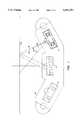
- FIG. 1depicts an assembly designed according to the present invention adapted for mounting in a standard watt-hour meter.
- FIGS. 2a-2gshow various views of the assembly of FIG. 1.
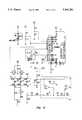
- FIG. 3is a schematic diagram of a particular embodiment of the present invention.
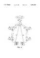
- FIG. 4shows a specific embodiment of the invention in a transmissive mode configuration.
- FIG. 5is a state diagram illustrating the operation of a particular embodiment of the present invention.
- FIG. 1depicts an assembly designed according to a particular embodiment of the present invention.
- a housing 10is adapted for mounting in a standard watt-hour meter.
- Two infrared emitting diodes (IREDs) 12are mounted in housing 10 on either side of a photo diode 14. IREDs 12 are mounted so that the infrared energy emitted from each IRED reflects off of the surface of a rotatable disk 16 and is received by photo diode 14. The infrared energy from each IRED 12 reflects off of slightly separated areas on the bottom surface of disk 16. The areas are separated in the direction of rotation of the disk.
- IREDsinfrared emitting diodes
- FIG. 1also illustrates the effect that a slight misalignment of the right IRED has on the angle of incidence of the reflected infrared energy.
- Solid line 18represents the center axis of the infrared energy beam for the preferred mounting angle
- dashed line 20represents the center axis of the beam for a 4° rotation in the mounting angle (angle ⁇ ).
- the preferred mounting anglesets up an angle of approximately 28.8° between the center axis of the infrared energy beam and the vertical.
- FIGS. 2a-2gshow various views of housing 10 of FIG. 1.
- FIG. 3is a schematic diagram of a particular embodiment of the present invention.
- the anodes of IREDs 12are pulsed by NPN driver transistors Q1 and Q2 under the firmware timing control of a microcontroller U3.
- the networkcomprising resistors R12, R18, R19, and thermistor RT1 determines the drive current level for IREDs 12, with RT1 providing compensation for the variation of IRED output irradiance with temperature.
- the photo diode 14receives input in the form of infrared energy reflected from a rotatable disk (not shown).
- Output current pulses from photo diode 14are then conditioned by a two stage ac-coupled operational amplifier circuit 22 with a decision threshold set by a voltage divider comprising R27, R35, and R29.
- the resulting outputis received by a comparator embedded in microcontroller U3.
- the comparator outputis a logic high for high amplitude pulses which exceed the decision threshold, and a logic low for low amplitude pulses which do not exceed the decision threshold.
- Firmware in microcontroller U3implements a periodic sequence of drive pulses and state machine logic for processing, tracking, and decoding the power consumption information contained in the reflected infrared energy.
- the firmwaredetermines disk rotational direction and accumulates the result as encoded registration of accumulated energy consumption, matching the external watt-hour meter's electro-mechanical register.
- IREDs 12are periodically pulsed in sequence. Sequence timing is determined by the microcontroller's crystal oscillator 13 which is stable with respect to initial tolerance, temperature, and aging to within ⁇ 500 parts per million. The resulting range of periods is 976.1 ⁇ s to 977.1 ⁇ s, with a preferred period of 976.6 ⁇ s.
- the left IREDis turned on first for a first interval. Both IREDs are then held off for a second interval. Then the right IRED is turned on for a third interval. The duration of the first interval is 17.28 ⁇ s to 17.30 ⁇ s, with a preferred duration of 17.29 ⁇ s.
- the duration of the second intervalis 0 to 1.018 ⁇ s, with a preferred duration of 1.017 ⁇ s.
- the duration of the third intervalis 19.32 ⁇ s to 19.34 ⁇ s, with a preferred duration of 19.33 ⁇ s.
- both IREDsare held off for the remainder of the period, the duration of this interval being 939.0 ⁇ s when the other intervals are the preferred durations.
- the output of photo diode 14follows this pulse sequence yielding high amplitude output current pulses when receiving reflected energy from the shiny metal disk surface; and receiving much lower amplitude pulses when receiving reflected energy from a specially installed stripe of infrared absorbing paint along a particular radius on the disk's bottom surface.
- the stripe's leading edgepasses through the left IRED's reflecting area, and then through the right IRED's reflecting area.
- the stripe's trailing edgeclears the left IRED, and then the right IRED, so that their radiated energy once again reflects off of the shinier metal disk surface to the photo diode.
- the pulse train which appears at the output of the photo diodehas well defined characteristics which are recognized and processed by the controller.
- exceptional conditionse.g., tampering
- the meter diskrotates in the reverse or clockwise direction. In such cases, the radiation-absorbing stripe passes over the right IRED first.
- the characteristics of the resulting pulse trainare distinctly different from those of the pulse train produced under normal conditions.
- the controlleris able to determine the direction of rotation of the disk due to the predictable variations in the photo diode signal.
- FIG. 4shows a specific embodiment of the invention in a transmissive mode configuration.
- assembly 10' with the two IREDs 12would be disposed on the opposite side of the rotatable disk 16' from the photosensitive device 14, the IREDs 12 being spatially separated in the direction of rotation of the disk 16'.
- the disk 16'would have at least one aperture 17 through which the photo diode 14 could sense the infrared pulses from the IREDs 12.
- the firmwarewould be suitably altered to recognize and process infrared pulses in a complementary manner with respect to the reflective embodiment described above.
- the present inventionmay also be adapted to recognize fractional rotations of the disk using multiple radiation-absorbing stripes or transmissive apertures.
- interval durations discussed aboverepresent only one embodiment of the invention. Interval durations can vary widely for different applications. For example, not only can the interval between the pulsing of the two IREDs be of zero duration, but these pulses can theoretically overlap. As long as the sampling rate is chosen so that the microcontroller can determine from which IRED a particular pulse is coming, it is not necessary to insert a positive interval between the two pulses. The maximum sampling rate is limited by such factors as the rise and fall times of the optoelectronic devices, amplifier settling times, and the amount of microcontroller time available.
- the durations of the IRED pulsescan also deviate substantially from the specific values of the above-described embodiment.
- Factors to be considered when determining interval durations for a specific applicationare the size of the features of the rotatable disk, the reflective (or transmissive) properties of the disk, and the maximum rotational rate of the disk.
- the pulse train repetition period and pulse durationsare constrained in accordance with the sampling theorem Nyquist rate, depending on these factors.
- Correct operation of the photo diode over the range of meter types, electronic component parameter variation, and operating conditionsdepends on the proper choice of the decision threshold level.
- the threshold levelis chosen so that it lies between pulse amplitudes estimated for the worst case (i.e., least reflective) shiny metal disk surface and the worst case (i.e., most reflective) infrared-absorbing stripe.
- FIG. 5is a state diagram illustrating the operation of the embodiment of FIG. 3 according to the firmware.
- the circuitrycomes up initially in state 5. State transitions occur according to the events L and R.
- the event Lrepresents that the left IRED has been energized and a photo diode output pulse which exceeds the decision threshold was registered.
- the event Rrepresents an equivalent event for the right IRED.
- L/Rrepresents the occurrence of both events L and R, while a bar over this symbol :represents the non-occurrence of the event. State changes do not occur where there is no change in the output pulse train.
- the firmware code represented by the state diagram of FIG. 4is included in Appendix A.
Landscapes
- Physics & Mathematics (AREA)
- General Physics & Mathematics (AREA)
- Optical Transform (AREA)
- Transition And Organic Metals Composition Catalysts For Addition Polymerization (AREA)
- Valve Device For Special Equipments (AREA)
- Analysing Materials By The Use Of Radiation (AREA)
- Analogue/Digital Conversion (AREA)
- Length Measuring Devices By Optical Means (AREA)
- Indicating Or Recording The Presence, Absence, Or Direction Of Movement (AREA)
Abstract
Description
__________________________________________________________________________Appendix A Firmware Listing __________________________________________________________________________323 .FORM 323 ;************************************************************ 323 ; PI State Machine 323 ; 323 ; Sample current PI input, flag PI sensor tamper 323 ; If input has changed, execute the state machine. 323 ;************************************************************ 323 0203 9FD2 LD B.#PORTLP ;Reg b => PI Sensor 323 0205 72 IFBIT PISENSE,[B] ;PI Sensor already on? 323 0206 BD0B6C RBIT PITMP,ESTAT ;Yes - Flag it for tamper report 323 0209 9FD0 LD B,#PORTLD ;Reg b => PI IREDs on this port 323 020B 7D SBIT IREDL,[B] ;Turn on left IRED and wait 323 020C 64 CLR A ;Reg a will accumulate result 323 020D A0 RC ;Carry will temp store result 323 020E 9FD2 LD B.#PORTLP ;Reg b => PI Sensor 323 0210 B8 NOP ;Wait 10μsec for valid output 323 0211 B8 NOP 323 0212 B8 NOP 323 0213 B8 NOP 323 0214 72 IFBIT PISENS,[B] ; Read result 323 0215 8A INC A ; and save it 323 0216 72 IFBIT PISENS,[B] ;Read result 323 0217 8A INC A ; and save it 323 0218 72 IFBIT PISENS,[B] ;Read result 323 0219 8A INC A ; and save it 323 021A 9FD0 LD B,#PORTLD 323 021C 6D RBIT IREDL,[B] ;Turn off left IRED 323 021D 7C SBIT IREDR,[B] ;Turn on right IRED and wait 323 021E 9301 IFGT A.#1 ;0-1 => 2-3 => on 323 0220 A1 SC ;Carry has left IRED result 323 0221 64 CLR A ;Reg a will have right IRED result 323 0222 9FD2 LD B,#PORTLP 323 0224 B8 NOP ;Wait 10μsec for valid output 323 0225 B8 NOP 323 0226 B8 NOP 323 0227 B8 NOP 323 0228 72 IFBIT PISENS,[B] ;Read result 323 0229 8A INC A ; and save it 323 022A 72 IFBIT PISENS,[B] ;Read result 323 022B 8A INC A ; and save it 323 022C 72 IFBIT PISENS,[B] ;Read result 323 022D 8A INC A ; and save it 323 022E 9FD0 LD B,#PORTLD 323 0230 6C RBIT IREDR.[B] ;Turn off right IRED 323 .FORM 323 0231 9301 IFGT A.#1 ;0-1 => off. 2-3 => on 323 0233 02 JP L10 323 0234 64 CLR A 323 0235 02 JP L20 323 L10: 323 0236 9801 LD A.#1 323 L20: ;Reg a has new sample 323 0238 A8 RLC A ;Reg a has new sample 323 0239 9600 XOR A.#TYPEI*(PIL!PIR) ;Set correct logic sense 323 023B 9F3C LD B.#INPI ;Reg b => Saved PI Input 323 023D 82 IFEQ A.[B] ;Is new reading a change? 323 023E 22A1 JMP PIDONE ; No - Skip further service 323 0240 A6 X A.[B] ; Yes - Store new value 323 0241 9847 LD A.#L(TBPI) ;Base of table of PI States 323 0243 BD3D84 ADD A.PISTAT ;Compute table index 323 0246 A5 JID ;Branch to correct state 323 TBPI: 323 0247 86 .BYTE L(CCW1) ;State 0: PI CCW1 323 0248 69 .BYTE L(CW1) ;State 1: PI CWI 323 0249 8E .BYTE L(CCW2) ;State 2: PI CCW2 323 024A 71 .BYTE L(CW2) ;State 3: PI CW2 323 024B 55 .BYTE L(PIC) ;State 4: PI Center 323 024C 4D .BYTE L(PIX) ;State 5: PI Initial 323 PIX: ;State 5: Initial PI machine state 323 024D TSTST 4,(PIL!PIR) 323 024D 9803 LD A,#(PIL!PIR) 323 024F 82 IFEQ A,[B] 323 0250 BC3D04 LD PISTAT.#4 323 0253 22A1 JMP PIDONE 323 PIC: ;State 4: Center PI Machine State 323 0255 TSTST 0.PIR 323 0255 9802 LD A.#PIR 323 0257 82 IFEQ A,[B] 323 0258 BC3D00 LD PISTAT.#0 323 025B TSTST 1.PIL 323 025B 9801 LD A.#PIL 323 025D 82 IFEQ A,[B] 323 025E BC3D01 LD PISTAT.#1 323 0261 TSTST 5.0 323 0261 9800 LD A.#0 323 0263 82 IFEQ A.[B] 323 0264 BC3D05 LD PISTAT.#5 323 0267 22A1 JMP PIDONE 323 .FORM 323 CW1: ;State 1: Clockwise 1 PI State 323 0269 TSTST 3.PIR 323 0269 9802 LD A.#PIR 323 026B 82 IFEQ A.[B] 323 026C BC3D03 LD PISTAT.#3 323 026F 224D JMP PIX 323 CW2: ;State 3: Clockwise 2 PI State 323 0271 TSTST 1.PIL 323 0271 9801 LD A.#PIL 323 0273 82 IFEQ A.[B] 323 0274 BC3D01 LD PISTAT.#1 323 0277 9803 LD A,#(PIL!PIR) 323 0279 B9 IFNE A,[B] 323 027A 22A1 JMP PIDONE 323 PLSCW ;Count (pulse) a clockwise hole 323 027C 9F3E LD B,# HOLCW 323 027E AE LD A,[B] 323 027F 8A INC A 323 0280 A6 X A,[B] 323 0281 BC3D04 LD PISTAT.#4 323 0284 22A1 R JMP PIDONE 323 CCW1: ;State 0: Counter-clockwise 1 PI State 323 0286 TSTST 2,PIL 323 0286 9801 LD A,#PIL 323 0288 82 IFEQ A,[B] 3232 0289 BC3D02 LD PISTAT.#2 323 028C 224D JMP PIX 323 CCW2: ;State 2: Counter-clockwise 2 PI State 323 028E TSTST 0,PIR 323 028E 9802 LD A,#PIR 323 0290 82 IFEQ A,[B] 323 0291 BC3D00 LD PISTAT,#0 323 0294 9803 LD A.#(PIL!PIR) 323 0296 B9 IFNE A,[B] 323 0297 22A1 R JMP PIDONE 323 PLSCCW: ;Count (pulse) a counter-clockwise hole 323 0299 9F3F LD B,#HOLCCW 323 029B AE LD A.[B] 323 029C 8A INC A 323 029D A6 X A,[B] 323 029E BC3D04 LD PISTAT.#4 323 ; jmp PIDone 323 PIDONE: __________________________________________________________________________
Claims (37)
Priority Applications (11)
| Application Number | Priority Date | Filing Date | Title |
|---|---|---|---|
| US08/069,704US5442281A (en) | 1993-06-01 | 1993-06-01 | Method and apparatus for deriving power consumption information from the angular motion of a rotating disk in a watt hour meter |
| NZ268713ANZ268713A (en) | 1993-06-01 | 1994-05-18 | Light pulse sensing of degree and direction of rotation of meter disk |
| CA002162267ACA2162267C (en) | 1993-06-01 | 1994-05-18 | Pulse initiator device |
| AU72009/94AAU679246B2 (en) | 1993-06-01 | 1994-05-18 | Pulse initiator device |
| CN94192318ACN1051372C (en) | 1993-06-01 | 1994-05-18 | Pulse initiator device |
| BR9406731ABR9406731A (en) | 1993-06-01 | 1994-05-18 | Apparatus for recording information about the angular movement of a rotating disk process to deduce information about the rotation of a rotating disk and watt-hour meter |
| JP50075695AJP3682297B2 (en) | 1993-06-01 | 1994-05-18 | Pulse starter |
| PCT/US1994/005500WO1994028428A1 (en) | 1993-06-01 | 1994-05-18 | Pulse initiator device |
| EP94921191AEP0803066B1 (en) | 1993-06-01 | 1994-05-18 | Pulse initiator device |
| DE69434506TDE69434506D1 (en) | 1993-06-01 | 1994-05-18 | PULSE INITIATOR DEVICE |
| KR1019950705362AKR100298762B1 (en) | 1993-06-01 | 1994-05-18 | Pulse Initiator |
Applications Claiming Priority (1)
| Application Number | Priority Date | Filing Date | Title |
|---|---|---|---|
| US08/069,704US5442281A (en) | 1993-06-01 | 1993-06-01 | Method and apparatus for deriving power consumption information from the angular motion of a rotating disk in a watt hour meter |
Publications (1)
| Publication Number | Publication Date |
|---|---|
| US5442281Atrue US5442281A (en) | 1995-08-15 |
Family
ID=22090686
Family Applications (1)
| Application Number | Title | Priority Date | Filing Date |
|---|---|---|---|
| US08/069,704Expired - Fee RelatedUS5442281A (en) | 1993-06-01 | 1993-06-01 | Method and apparatus for deriving power consumption information from the angular motion of a rotating disk in a watt hour meter |
Country Status (11)
| Country | Link |
|---|---|
| US (1) | US5442281A (en) |
| EP (1) | EP0803066B1 (en) |
| JP (1) | JP3682297B2 (en) |
| KR (1) | KR100298762B1 (en) |
| CN (1) | CN1051372C (en) |
| AU (1) | AU679246B2 (en) |
| BR (1) | BR9406731A (en) |
| CA (1) | CA2162267C (en) |
| DE (1) | DE69434506D1 (en) |
| NZ (1) | NZ268713A (en) |
| WO (1) | WO1994028428A1 (en) |
Cited By (8)
| Publication number | Priority date | Publication date | Assignee | Title |
|---|---|---|---|---|
| US5874732A (en)* | 1995-12-22 | 1999-02-23 | Ramar Technology Ltd. | Rotation sensor |
| US6232885B1 (en) | 1998-10-15 | 2001-05-15 | Schlumberger Resource Management Services, Inc. | Electricity meter |
| US20050000302A1 (en)* | 2003-06-13 | 2005-01-06 | Dan Winter | Meter register having an encoder for measuring material flow and an algorithm to selectively block signal transmission |
| US6885185B1 (en) | 1998-12-01 | 2005-04-26 | Itron Electricity Metering, Inc. | Modular meter configuration and methodology |
| US20060050285A1 (en)* | 2004-09-06 | 2006-03-09 | Weller Keith S | Position Encoder with Directional Output |
| US20060162467A1 (en)* | 2004-09-23 | 2006-07-27 | Arad Measuring Technologies, Ltd. | Meter register having an encoder |
| US8842712B2 (en) | 2011-03-24 | 2014-09-23 | Gregory C. Hancock | Methods and apparatuses for reception of frequency-hopping spread spectrum radio transmissions |
| CN108917653A (en)* | 2018-03-20 | 2018-11-30 | 刘红阳 | Rotational angle measurement method and device |
Families Citing this family (2)
| Publication number | Priority date | Publication date | Assignee | Title |
|---|---|---|---|---|
| GB0205788D0 (en)* | 2002-03-12 | 2002-04-24 | Advanced Technology Ramar Ltd | Digital disc rotation counter |
| GB2463518A (en)* | 2008-09-12 | 2010-03-24 | Alertme Com Ltd | Automated meter reading device |
Citations (27)
| Publication number | Priority date | Publication date | Assignee | Title |
|---|---|---|---|---|
| US1878658A (en)* | 1929-04-03 | 1932-09-20 | Westinghouse Electric & Mfg Co | Watthour meter testing device |
| US3127594A (en)* | 1960-09-15 | 1964-03-31 | Robert L Farr | Remote metering device |
| US3740633A (en)* | 1971-03-03 | 1973-06-19 | Honeywell Inf Systems | Frequency-to-voltage converter device |
| US4034292A (en)* | 1976-02-18 | 1977-07-05 | Westinghouse Electric Corporation | Direction sensitive opto-electronic pulse initiator for electrical meters |
| US4162399A (en)* | 1977-09-16 | 1979-07-24 | Bei Electronics, Inc. | Optical encoder with fiber optics |
| US4281325A (en)* | 1979-08-17 | 1981-07-28 | American Science And Engineering, Inc. | Positive feedback meter pulse initiator |
| US4298839A (en)* | 1978-03-31 | 1981-11-03 | Westinghouse Electric Corp. | Programmable AC electric energy meter having radiation responsive external data interface |
| US4321531A (en)* | 1979-09-17 | 1982-03-23 | Sangamo-Weston Inc. | Direction sensitive pulse initiator for a wattmeter |
| US4327362A (en)* | 1978-10-23 | 1982-04-27 | Rockwell International Corporation | Meter rotor rotation optical sensor |
| US4328463A (en)* | 1980-03-27 | 1982-05-04 | Rca Corporation | Encoder for recording incremental changes |
| US4350980A (en)* | 1980-02-21 | 1982-09-21 | Energy Optics, Inc. | Electric meter consumption and demand communicator |
| US4500870A (en)* | 1981-09-29 | 1985-02-19 | Eotec Corporation | Method and components for remote reading of utility meters |
| US4587513A (en)* | 1984-06-25 | 1986-05-06 | Energy Innovations, Inc. | Noncontact shaft angle detector |
| US4588982A (en)* | 1984-09-13 | 1986-05-13 | Sangamo Weston, Inc. | Optical shaft encoder |
| US4604725A (en)* | 1982-05-18 | 1986-08-05 | The Marconi Company Limited | Rotary apparatus having code track with pseudo-random binary digit sequence for indicating rotational position |
| US4650995A (en)* | 1984-01-18 | 1987-03-17 | Alps Electric Co., Ltd. | Reflection type optical rotary encoder |
| US4660036A (en)* | 1985-05-17 | 1987-04-21 | Rockwell International Corporation | Amplified motion encoder |
| US4670737A (en)* | 1984-09-13 | 1987-06-02 | Sangamo Weston, Inc. | Method of initializing an optical encoder |
| US4678907A (en)* | 1984-06-21 | 1987-07-07 | Microtel Limited | Optical scanner and sensor for monitoring power consumption |
| US4712372A (en)* | 1985-09-18 | 1987-12-15 | Avco Corporation | Overspeed system redundancy monitor |
| US4713610A (en)* | 1984-11-29 | 1987-12-15 | Westinghouse Electric Corp. | Electric meter with improved sensing head assembly |
| US4792677A (en)* | 1986-08-29 | 1988-12-20 | Domestic Automation Company, Inc. | System for use with a utility meter for recording time of energy use |
| US4827123A (en)* | 1986-04-11 | 1989-05-02 | Sangamo Weston, Inc. | Direction sensitive optical shaft encoder |
| US4956551A (en)* | 1987-12-03 | 1990-09-11 | Infas Institut Fur Angewandte Sozialwissenscheft Gmbh | Sensor for consumption measurements in a household measuring system |
| US5021735A (en)* | 1989-01-10 | 1991-06-04 | Heidelberger Druckmaschinen Ag | Opto-electronic bachometer and position detector of an electric motor |
| DE4013936A1 (en)* | 1990-04-30 | 1991-10-31 | Dieter Rippel | Optical absolute encoder for measuring angular increments - uses image information mask cooperating with CCD sensor or LED array |
| US5130641A (en)* | 1990-11-29 | 1992-07-14 | Amrplus Partners | Eddy wheel edge sensor |
- 1993
- 1993-06-01USUS08/069,704patent/US5442281A/ennot_activeExpired - Fee Related
- 1994
- 1994-05-18KRKR1019950705362Apatent/KR100298762B1/ennot_activeExpired - Fee Related
- 1994-05-18CNCN94192318Apatent/CN1051372C/ennot_activeExpired - Fee Related
- 1994-05-18BRBR9406731Apatent/BR9406731A/ennot_activeIP Right Cessation
- 1994-05-18NZNZ268713Apatent/NZ268713A/enunknown
- 1994-05-18WOPCT/US1994/005500patent/WO1994028428A1/enactiveIP Right Grant
- 1994-05-18DEDE69434506Tpatent/DE69434506D1/ennot_activeExpired - Lifetime
- 1994-05-18CACA002162267Apatent/CA2162267C/ennot_activeExpired - Fee Related
- 1994-05-18JPJP50075695Apatent/JP3682297B2/ennot_activeExpired - Fee Related
- 1994-05-18AUAU72009/94Apatent/AU679246B2/ennot_activeCeased
- 1994-05-18EPEP94921191Apatent/EP0803066B1/ennot_activeExpired - Lifetime
Patent Citations (27)
| Publication number | Priority date | Publication date | Assignee | Title |
|---|---|---|---|---|
| US1878658A (en)* | 1929-04-03 | 1932-09-20 | Westinghouse Electric & Mfg Co | Watthour meter testing device |
| US3127594A (en)* | 1960-09-15 | 1964-03-31 | Robert L Farr | Remote metering device |
| US3740633A (en)* | 1971-03-03 | 1973-06-19 | Honeywell Inf Systems | Frequency-to-voltage converter device |
| US4034292A (en)* | 1976-02-18 | 1977-07-05 | Westinghouse Electric Corporation | Direction sensitive opto-electronic pulse initiator for electrical meters |
| US4162399A (en)* | 1977-09-16 | 1979-07-24 | Bei Electronics, Inc. | Optical encoder with fiber optics |
| US4298839A (en)* | 1978-03-31 | 1981-11-03 | Westinghouse Electric Corp. | Programmable AC electric energy meter having radiation responsive external data interface |
| US4327362A (en)* | 1978-10-23 | 1982-04-27 | Rockwell International Corporation | Meter rotor rotation optical sensor |
| US4281325A (en)* | 1979-08-17 | 1981-07-28 | American Science And Engineering, Inc. | Positive feedback meter pulse initiator |
| US4321531A (en)* | 1979-09-17 | 1982-03-23 | Sangamo-Weston Inc. | Direction sensitive pulse initiator for a wattmeter |
| US4350980A (en)* | 1980-02-21 | 1982-09-21 | Energy Optics, Inc. | Electric meter consumption and demand communicator |
| US4328463A (en)* | 1980-03-27 | 1982-05-04 | Rca Corporation | Encoder for recording incremental changes |
| US4500870A (en)* | 1981-09-29 | 1985-02-19 | Eotec Corporation | Method and components for remote reading of utility meters |
| US4604725A (en)* | 1982-05-18 | 1986-08-05 | The Marconi Company Limited | Rotary apparatus having code track with pseudo-random binary digit sequence for indicating rotational position |
| US4650995A (en)* | 1984-01-18 | 1987-03-17 | Alps Electric Co., Ltd. | Reflection type optical rotary encoder |
| US4678907A (en)* | 1984-06-21 | 1987-07-07 | Microtel Limited | Optical scanner and sensor for monitoring power consumption |
| US4587513A (en)* | 1984-06-25 | 1986-05-06 | Energy Innovations, Inc. | Noncontact shaft angle detector |
| US4588982A (en)* | 1984-09-13 | 1986-05-13 | Sangamo Weston, Inc. | Optical shaft encoder |
| US4670737A (en)* | 1984-09-13 | 1987-06-02 | Sangamo Weston, Inc. | Method of initializing an optical encoder |
| US4713610A (en)* | 1984-11-29 | 1987-12-15 | Westinghouse Electric Corp. | Electric meter with improved sensing head assembly |
| US4660036A (en)* | 1985-05-17 | 1987-04-21 | Rockwell International Corporation | Amplified motion encoder |
| US4712372A (en)* | 1985-09-18 | 1987-12-15 | Avco Corporation | Overspeed system redundancy monitor |
| US4827123A (en)* | 1986-04-11 | 1989-05-02 | Sangamo Weston, Inc. | Direction sensitive optical shaft encoder |
| US4792677A (en)* | 1986-08-29 | 1988-12-20 | Domestic Automation Company, Inc. | System for use with a utility meter for recording time of energy use |
| US4956551A (en)* | 1987-12-03 | 1990-09-11 | Infas Institut Fur Angewandte Sozialwissenscheft Gmbh | Sensor for consumption measurements in a household measuring system |
| US5021735A (en)* | 1989-01-10 | 1991-06-04 | Heidelberger Druckmaschinen Ag | Opto-electronic bachometer and position detector of an electric motor |
| DE4013936A1 (en)* | 1990-04-30 | 1991-10-31 | Dieter Rippel | Optical absolute encoder for measuring angular increments - uses image information mask cooperating with CCD sensor or LED array |
| US5130641A (en)* | 1990-11-29 | 1992-07-14 | Amrplus Partners | Eddy wheel edge sensor |
Cited By (17)
| Publication number | Priority date | Publication date | Assignee | Title |
|---|---|---|---|---|
| US5874732A (en)* | 1995-12-22 | 1999-02-23 | Ramar Technology Ltd. | Rotation sensor |
| US6232885B1 (en) | 1998-10-15 | 2001-05-15 | Schlumberger Resource Management Services, Inc. | Electricity meter |
| US6617978B2 (en) | 1998-10-15 | 2003-09-09 | Schlumbergersema Inc. | Electricity meter |
| US20050162149A1 (en)* | 1998-12-01 | 2005-07-28 | Makinson David N. | Modular meter configuration and methodology |
| US7701199B2 (en) | 1998-12-01 | 2010-04-20 | Itron, Inc. | Modular meter configuration and methodology |
| US6885185B1 (en) | 1998-12-01 | 2005-04-26 | Itron Electricity Metering, Inc. | Modular meter configuration and methodology |
| US7663503B2 (en) | 2003-06-13 | 2010-02-16 | Arad Measuring Technologies Ltd. | Meter register having an encoder for measuring material flow and an algorithm to selectively block signal transmission |
| US7135986B2 (en) | 2003-06-13 | 2006-11-14 | Arad Measuring Technologies Ltd. | Meter register having an encoder for measuring material flow and an algorithm to selectively block signal transmission |
| US20070033985A1 (en)* | 2003-06-13 | 2007-02-15 | Arad Measuring Technologies Ltd. | Meter register having an encoder for measuring material flow and an algorithm to selectively block signal transmission |
| WO2004111576A3 (en)* | 2003-06-13 | 2005-03-31 | Arad Measuring Technologies Lt | Flow meter having an optical encoder and an algorithm to selectively block signal transmission |
| US20050000302A1 (en)* | 2003-06-13 | 2005-01-06 | Dan Winter | Meter register having an encoder for measuring material flow and an algorithm to selectively block signal transmission |
| EP2362187A3 (en)* | 2003-06-13 | 2014-09-03 | Arad Measuring Technologies Ltd. | Meter register having an encoder for measuring material flow and an algorithm to selectively block signal transmission |
| US20060050285A1 (en)* | 2004-09-06 | 2006-03-09 | Weller Keith S | Position Encoder with Directional Output |
| US20060162467A1 (en)* | 2004-09-23 | 2006-07-27 | Arad Measuring Technologies, Ltd. | Meter register having an encoder |
| US7267014B2 (en) | 2004-09-23 | 2007-09-11 | Arad Measuring Technologies Ltd. | Meter register having an encoder |
| US8842712B2 (en) | 2011-03-24 | 2014-09-23 | Gregory C. Hancock | Methods and apparatuses for reception of frequency-hopping spread spectrum radio transmissions |
| CN108917653A (en)* | 2018-03-20 | 2018-11-30 | 刘红阳 | Rotational angle measurement method and device |
Also Published As
| Publication number | Publication date |
|---|---|
| CN1051372C (en) | 2000-04-12 |
| EP0803066A4 (en) | 1997-12-03 |
| JP3682297B2 (en) | 2005-08-10 |
| EP0803066A1 (en) | 1997-10-29 |
| CA2162267C (en) | 2004-08-10 |
| DE69434506D1 (en) | 2006-02-23 |
| CN1125003A (en) | 1996-06-19 |
| BR9406731A (en) | 1996-01-30 |
| EP0803066B1 (en) | 2005-10-12 |
| NZ268713A (en) | 1996-10-28 |
| AU7200994A (en) | 1994-12-20 |
| AU679246B2 (en) | 1997-06-26 |
| JPH08511095A (en) | 1996-11-19 |
| WO1994028428A1 (en) | 1994-12-08 |
| KR100298762B1 (en) | 2001-10-22 |
| CA2162267A1 (en) | 1994-12-08 |
Similar Documents
| Publication | Publication Date | Title |
|---|---|---|
| US5442281A (en) | Method and apparatus for deriving power consumption information from the angular motion of a rotating disk in a watt hour meter | |
| EP0003288B1 (en) | Modular rotary shaft incremental encoder and a fixture and a method for pre-aligning an optical encoder stator | |
| JPH0462087B2 (en) | ||
| DK141142B (en) | A record carrier on which information is recorded in optically readable form, an apparatus for reading such a record carrier, and an enrollment apparatus for forming such a record carrier. | |
| EP0553332B1 (en) | Remote meter reading | |
| US4264897A (en) | Meter register encoder including electronics providing remote reading capability | |
| US5874731A (en) | Ambient light filter | |
| US5874732A (en) | Rotation sensor | |
| US5113130A (en) | Testing operation of electric energy meter optics system | |
| US5130641A (en) | Eddy wheel edge sensor | |
| US5268633A (en) | Testing operation of electric energy meter optics system | |
| EP0547879B1 (en) | Meter output devices | |
| JP3102268B2 (en) | Magnetic detector | |
| US4660035A (en) | Remote monitoring system | |
| US4608563A (en) | Remote monitoring induction telemetering system | |
| US5241306A (en) | System and method for introducing meter sensor hysteresis | |
| KR900003694B1 (en) | Disc apparatus | |
| SU1137352A1 (en) | Photoelectric meter of torque | |
| JP2785187B2 (en) | Rotation detection device | |
| US4757308A (en) | Position detector with snap action toggle | |
| KR100528022B1 (en) | Meter using magnetoresistive element | |
| SU703854A1 (en) | Device for cyclic teleindication | |
| GB2253879A (en) | Security clip for commodity meters | |
| SU1104573A1 (en) | Device for checking shaft turn angle encoder | |
| JPS62212800A (en) | Rotary signal vanishment alarm |
Legal Events
| Date | Code | Title | Description |
|---|---|---|---|
| AS | Assignment | Owner name:ENSCAN, INC., WASHINGTON Free format text:ASSIGNMENT OF ASSIGNORS INTEREST;ASSIGNORS:FRISCH, MYRON ISRAEL;NAUMAAN, AHMED;REEL/FRAME:006754/0661 Effective date:19930729 | |
| AS | Assignment | Owner name:ITRON, INC., WASHINGTON Free format text:MERGER;ASSIGNOR:ENSCAN, INC.;REEL/FRAME:007677/0739 Effective date:19931223 | |
| FEPP | Fee payment procedure | Free format text:PAYOR NUMBER ASSIGNED (ORIGINAL EVENT CODE: ASPN); ENTITY STATUS OF PATENT OWNER: LARGE ENTITY | |
| CC | Certificate of correction | ||
| AS | Assignment | Owner name:ITRON MINNESOTA, INC., MINNESOTA Free format text:ASSIGNMENT OF ASSIGNORS INTEREST;ASSIGNOR:ITRON, INC.;REEL/FRAME:009052/0570 Effective date:19980306 | |
| FPAY | Fee payment | Year of fee payment:4 | |
| FEPP | Fee payment procedure | Free format text:PAYOR NUMBER ASSIGNED (ORIGINAL EVENT CODE: ASPN); ENTITY STATUS OF PATENT OWNER: LARGE ENTITY Free format text:PAYER NUMBER DE-ASSIGNED (ORIGINAL EVENT CODE: RMPN); ENTITY STATUS OF PATENT OWNER: LARGE ENTITY | |
| AS | Assignment | Owner name:ITRON, INC., WASHINGTON Free format text:ASSIGNMENT OF ASSIGNORS INTEREST;ASSIGNOR:ITRON MINNESOTA, INC.;REEL/FRAME:011934/0085 Effective date:20010601 | |
| AS | Assignment | Owner name:WELLS FARGO BANK, NATIONAL ASSOCIATION, AS ADMINIS Free format text:SECURITY INTEREST;ASSIGNOR:ITRON, INC.;REEL/FRAME:013496/0918 Effective date:20030303 | |
| REMI | Maintenance fee reminder mailed | ||
| FPAY | Fee payment | Year of fee payment:8 | |
| SULP | Surcharge for late payment | Year of fee payment:7 | |
| AS | Assignment | Owner name:ITRON, INC., WASHINGTON Free format text:RELEASE OF SECURITY INTEREST;ASSIGNOR:WELLS FARGO BANK, NATIONAL ASSOCIATION, AS ADMINISTRATIVE AGENT;REEL/FRAME:014822/0081 Effective date:20040701 | |
| AS | Assignment | Owner name:WELLS FARGO BANK, NATIONAL ASSOCIATION, AS ADMINIS Free format text:SECURITY AGREEMENT;ASSIGNOR:ITRON, INC.;REEL/FRAME:014830/0587 Effective date:20040701 | |
| REMI | Maintenance fee reminder mailed | ||
| AS | Assignment | Owner name:WELLS FARGO BANK, NATIONAL ASSOCIATION,WASHINGTON Free format text:SECURITY AGREEMENT;ASSIGNOR:ITRON, INC.;REEL/FRAME:019204/0544 Effective date:20070418 Owner name:WELLS FARGO BANK, NATIONAL ASSOCIATION, WASHINGTON Free format text:SECURITY AGREEMENT;ASSIGNOR:ITRON, INC.;REEL/FRAME:019204/0544 Effective date:20070418 | |
| AS | Assignment | Owner name:ITRON, INC., WASHINGTON Free format text:TERMINATION AND RELEASE OF SECURITY INTEREST IN INTELLECTUAL PROPERTY;ASSIGNOR:WELLS FARGO BANK, NATIONAL ASSOCIATION;REEL/FRAME:019466/0451 Effective date:20070418 | |
| LAPS | Lapse for failure to pay maintenance fees | ||
| STCH | Information on status: patent discontinuation | Free format text:PATENT EXPIRED DUE TO NONPAYMENT OF MAINTENANCE FEES UNDER 37 CFR 1.362 | |
| FP | Lapsed due to failure to pay maintenance fee | Effective date:20070815 | |
| AS | Assignment | Owner name:ITRON, INC., WASHINGTON Free format text:RELEASE BY SECURED PARTY;ASSIGNOR:WELLS FARGO BANK, NATIONAL ASSOCIATION;REEL/FRAME:026749/0263 Effective date:20110805 |