US5440932A - Pressure transducer including coaxial rings - Google Patents
Pressure transducer including coaxial ringsDownload PDFInfo
- Publication number
- US5440932A US5440932AUS08/217,645US21764594AUS5440932AUS 5440932 AUS5440932 AUS 5440932AUS 21764594 AUS21764594 AUS 21764594AUS 5440932 AUS5440932 AUS 5440932A
- Authority
- US
- United States
- Prior art keywords
- outer member
- transducer
- stress tube
- gap
- flexure
- Prior art date
- Legal status (The legal status is an assumption and is not a legal conclusion. Google has not performed a legal analysis and makes no representation as to the accuracy of the status listed.)
- Expired - Lifetime
Links
Images


Classifications
- B—PERFORMING OPERATIONS; TRANSPORTING
- B29—WORKING OF PLASTICS; WORKING OF SUBSTANCES IN A PLASTIC STATE IN GENERAL
- B29C—SHAPING OR JOINING OF PLASTICS; SHAPING OF MATERIAL IN A PLASTIC STATE, NOT OTHERWISE PROVIDED FOR; AFTER-TREATMENT OF THE SHAPED PRODUCTS, e.g. REPAIRING
- B29C45/00—Injection moulding, i.e. forcing the required volume of moulding material through a nozzle into a closed mould; Apparatus therefor
- B29C45/17—Component parts, details or accessories; Auxiliary operations
- B29C45/76—Measuring, controlling or regulating
- B29C45/77—Measuring, controlling or regulating of velocity or pressure of moulding material
- G—PHYSICS
- G01—MEASURING; TESTING
- G01L—MEASURING FORCE, STRESS, TORQUE, WORK, MECHANICAL POWER, MECHANICAL EFFICIENCY, OR FLUID PRESSURE
- G01L9/00—Measuring steady of quasi-steady pressure of fluid or fluent solid material by electric or magnetic pressure-sensitive elements; Transmitting or indicating the displacement of mechanical pressure-sensitive elements, used to measure the steady or quasi-steady pressure of a fluid or fluent solid material, by electric or magnetic means
- G01L9/0001—Transmitting or indicating the displacement of elastically deformable gauges by electric, electro-mechanical, magnetic or electro-magnetic means
- G01L9/0007—Transmitting or indicating the displacement of elastically deformable gauges by electric, electro-mechanical, magnetic or electro-magnetic means using photoelectric means
- B—PERFORMING OPERATIONS; TRANSPORTING
- B29—WORKING OF PLASTICS; WORKING OF SUBSTANCES IN A PLASTIC STATE IN GENERAL
- B29C—SHAPING OR JOINING OF PLASTICS; SHAPING OF MATERIAL IN A PLASTIC STATE, NOT OTHERWISE PROVIDED FOR; AFTER-TREATMENT OF THE SHAPED PRODUCTS, e.g. REPAIRING
- B29C2945/00—Indexing scheme relating to injection moulding, i.e. forcing the required volume of moulding material through a nozzle into a closed mould
- B29C2945/76—Measuring, controlling or regulating
- B29C2945/76003—Measured parameter
- B29C2945/76006—Pressure
- B—PERFORMING OPERATIONS; TRANSPORTING
- B29—WORKING OF PLASTICS; WORKING OF SUBSTANCES IN A PLASTIC STATE IN GENERAL
- B29C—SHAPING OR JOINING OF PLASTICS; SHAPING OF MATERIAL IN A PLASTIC STATE, NOT OTHERWISE PROVIDED FOR; AFTER-TREATMENT OF THE SHAPED PRODUCTS, e.g. REPAIRING
- B29C2945/00—Indexing scheme relating to injection moulding, i.e. forcing the required volume of moulding material through a nozzle into a closed mould
- B29C2945/76—Measuring, controlling or regulating
- B29C2945/76003—Measured parameter
- B29C2945/7604—Temperature
- B—PERFORMING OPERATIONS; TRANSPORTING
- B29—WORKING OF PLASTICS; WORKING OF SUBSTANCES IN A PLASTIC STATE IN GENERAL
- B29C—SHAPING OR JOINING OF PLASTICS; SHAPING OF MATERIAL IN A PLASTIC STATE, NOT OTHERWISE PROVIDED FOR; AFTER-TREATMENT OF THE SHAPED PRODUCTS, e.g. REPAIRING
- B29C2945/00—Indexing scheme relating to injection moulding, i.e. forcing the required volume of moulding material through a nozzle into a closed mould
- B29C2945/76—Measuring, controlling or regulating
- B29C2945/76003—Measured parameter
- B29C2945/76083—Position
- B—PERFORMING OPERATIONS; TRANSPORTING
- B29—WORKING OF PLASTICS; WORKING OF SUBSTANCES IN A PLASTIC STATE IN GENERAL
- B29C—SHAPING OR JOINING OF PLASTICS; SHAPING OF MATERIAL IN A PLASTIC STATE, NOT OTHERWISE PROVIDED FOR; AFTER-TREATMENT OF THE SHAPED PRODUCTS, e.g. REPAIRING
- B29C2945/00—Indexing scheme relating to injection moulding, i.e. forcing the required volume of moulding material through a nozzle into a closed mould
- B29C2945/76—Measuring, controlling or regulating
- B29C2945/76451—Measurement means
- B29C2945/76461—Optical, e.g. laser
Definitions
- the present inventionrelates generally to pressure transducers and pertains, more particularly, to pressure transducers for use with injection molding machines.
- Injection molding machinesare used to manufacture plastic and metal parts. Injection molding machines typically include a reservoir of molten plastic and a nozzle through which the molten plastic is forced at high pressures into a mold. The plastic is thereafter packed and cooled to form the part. In the manufacture of such parts, it is important to precisely determine the pressure of the injected melt to maintain accuracy of the part because the part must be made at a constant pressure. This is so because otherwise the resulting part may include voids, ripples, poor dimensional accuracy or the like.
- pressure transducer deviceswhich can accurately measure the pressure of molten plastic within injection molding machines. Attaining accuracy in pressure measurements by injection molding machine pressure transducers is difficult because pressures within such injection molding machines may be as high as within the range of 40-50,000 psi and the temperature may be as high as approximately 500° C. In other words, such pressure transducers must be able to accurately measure and withstand pressures within the range of 40-50,000 psi and operate accurately within an environment having temperatures up to approximately 500° C. Additionally, such pressure transducers are faced with the following constraints: 1. the pressure transducer must have low working stresses to avoid metal fatigue cracking under repetative cyclic loading; 2.
- the pressure transducerfor economic practicality must be physically arranged such that the chamber/nozzle area can easily be integrated within the injection molding machine; and 3. the pressure transducer must not disrupt the plastic flow or have pockets where plastic will remain and eventually degrade and cause staining of the parts as the degraded plastic moves into the flow.
- a general object of the present inventionis to provide an injection molding machine pressure transducer which can accurately measure pressures of molten plastic within such machines.
- a further object of the present inventionis to provide an injection molding machine pressure transducer which is easily integratable with existing injection molding machines.
- a pressure transducerfor determining pressure of material in an injection molding machine which includes a housing coupled to a nozzle of an injection molding machine.
- a hollow stress tubeattached to the housing, through which material of the injection molding machine flows, bellows in response to pressure from the material.
- An open outer ringand is coupled to the stress tube such that the outer ring expands, causing displacement of the outer ring about the opening, when the stress tube bellows.
- a displacement sensordetermines displacement of the outer ring across the opening which displacement is related to the pressure of the material.
- the pressure transduceralso includes a temperature sensor for determining the operating temperature thereof.
- the displacement sensorincludes an optical arrangement.
- the housing of the pressure transduceris mechanically retained in a nozzle bore of the injection molding machine.
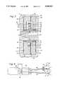
- FIG. 1is a cross-sectional view of the pressure transducer of the present invention retained within the nozzle of an injection molding machine;
- FIG. 2is a cross-sectional view taken along lines 2--2 of FIG. 1 illustrating components of the pressure transducer
- FIG. 3is a cross-sectional view taken along lines 3--3 of FIG. 2 showing further details of the components of the pressure transducer;
- FIG. 4is a block diagram of the optical arrangement of the displacement sensor of the pressure transducer.
- FIG. 5is a cross-sectional view of an alternate embodiment of the pressure transducer shown mechanically retained within the nozzle of an injection molding machine.
- a pressure transducerfor use in an injection molding machine.
- the pressure transduceris secured within a bore of a nozzle of an injection molding machine and includes an inner stress tube ring through which the molten plastic of the injection molding machine flows.
- An outer ring having an openingis coaxial with the inner stress tube ring and is attached thereto with flexures.
- the stress tubebellows in response to pressure from the molten plastic and translates this pressure to the outer open ring through the flexures.
- an opening of the outer ringwidens, displacing the outer ring at both sides of the opening, which displacement is determined by the displacement sensor. This displacement is directly proportional to the pressure of the molten plastic and the pressure is determined from the value of the displacement.
- FIGS. 2 and 3illustrate further details of the components of the pressure transducer.
- FIG. 4illustrates a preferred optical displacement sensor arrangement.
- FIG. 5shows an alternate embodiment of the pressure transducer within a nozzle of an injection molding machine.
- FIG. 1illustrates the pressure transducer 10 retained within the bore 18 of nozzle 12 of an injection molding machine.
- the pressure transducer 10is mechanically retained with the bore 18 between outer nozzle piece 14 and inner nozzle piece 16 of nozzle 12 of the injection molding machine.
- the outer nozzle piece 14 and inner nozzle piece 16include interengaging threads 13 such that inner nozzle piece 16 can be screwed into outer nozzle piece 14 and sealed therein.
- Molten plastic 22flows through canal 20 of the injection molding machine.
- Pressure transducer 10is concentric about canal 20 and the molten plastic 22 flows through pressure transducer 10.
- the pressure transducer 10measures the pressure of the molten plastic 22.
- Pressure transducer 10is shown in cross-section in FIG. 2. As shown, pressure transducer 10 includes a housing 24, an inner stress tube 26, through which the molten plastic 22 flows, and an outer open ring 28 coaxial and concentric with inner stress tube 26. Outer open ring 28 is connected to inner stress tube 26 through flexures 30, 32, 34, 36, and 38. Flexure 38 is an anchor support flexure which is thicker than the other flexure members and is located diametrically opposite opening 40.
- the inner stress tube ring 26deflects radially (shown by the arrows R) in response to pressure from molten plastic 22. This radial deflection or bellowing is translated to the outer open ring 28 by the flexures 30, 32, 34, 36 and 38.
- An opening 40is included in outer open ring 28.
- Anchor flexure 38acts as a fulcrum upon which the outer ring opens. Because the outer open ring encircles the inner stress tube, it mirrors its radial displacement through the flexures.
- the pressure of the molten plasticis directly proportional to the radial expansion of the inner stress tube.
- Displacement of the outer open ring at both sides of the opening 40is directly proportional to the radial expansion of the inner stress tube.
- Displacement sensor 42is attached to outer open ring at one side of the opening and mirrored bracket 44 is attached to the outer open ring at the other side of the opening.
- Displacement sensor 42determines the amount of the opening of the outer open ring 28 at character 40. From this displacement value, the transducer determines the pressure sensed.
- Optical fibers 46 and 48, along with mirror 44,are combined to create a displacement sensor 42, the operation of which will be described hereinafter.
- Temperature sensor 50is provided at the surface of the stress tube 26 to determine the operating temperature of the transducer and to provide a temperature compensation at a pressure of zero.
- Flexures 30-38translate the radial expansion from the stress tube 26 to the outer ring 28. It is important that the flexures be axially rigid to translate the expansion with minimum deflection. In addition, it is important that the flexures be circumferentially or laterally flexible allowing the opening 40 to widen.
- the inner stress tube radial expansionis magnified at the opening 40 by approximately 2 ⁇ . For a stress tube radial deflection of 0.0008 inches, a gap opening of approximately 0.005 inches occurs.
- the inner stress tube ring 26is attached to transducer housing 24 through copper brazes 52 and 54.
- the transducer housing 24includes two pieces which are attached together by copper braze 56.
- the housing bodyis preferably made from stainless steel and is designed such that the transducer can withstand high pressure from the nozzle.
- Contoured feet 58, 60, 62 and 64are provided in transducer housing 24 to aid in the mechanical retention and sealing within the bore to the nozzle 12.
- the contoured feetprovide a metal to metal seal and also provide mechanical rigidity.
- inner stress tube ring 26directly contacts molten plastic 22 which provides pressure thereto.
- Pressure transducer 10is heat sensitive. Therefore, temperature sensor 50 is used to sense the temperature thereat and a feedback arrangement (not shown) is used to provide electronic thermal zero compensation to alter the characteristics of the transducer based on temperature changes sensed by sensor 50. Accordingly, zero shift temperature characteristic information is determined for the transducer and used in the temperature feedback and compensation circuitry. Additionally, the transducer is calibrated during initial tests when known accurate pressures are applied to the transducer and the displacement of the opening is thereafter measured. Relationships are determined for pressures and displacement levels, such that the transducer can compute pressure values based upon particular displacement.
- the design of the transduceris fundamentally simple which offers certain advantages.
- the stress tube, flexures and outer ringcan be machined from a single piece of metal or separate pieces and then copper brazed and/or welded together to complete the mechanical assembly.
- the maximum pressure capability of the transduceris approximately 50,000 psi.
- the inner stress tubeis stiff and includes the motion-amplified outer ring coaxial therewith, the transducer itself provides low stress with ample deflection which aids in the longevity of the transducer. In the arrangement shown in FIG. 1, no drilled holes are provided which penetrate the bore. Therefore, the bore remains clean so as to not alter any pressure characteristics of the injection molding machine.
- the pressure transduceris located at the nozzle of the injection molding machine, the pressure is determined at the point just before the molten plastic is injected into the mold which is desired.
- FIG. 4is a block diagram illustrating a preferred arrangement of the displacement sensor 42.
- This arrangementis an optical fotonic arrangement including an input optical fiber 46 and an output optical fiber 48.
- An LED 66, or light sourcegenerates light, a small portion 70 of which is reflected to the photodetector 68. A majority of the remainder of the light produced is inputted into the input optical fiber 46 as an input light ray 72.
- the light produced by LED 66is input through lens 71 which focuses the light.
- Photodetector 68determines the level of the reflected ray 70, the desired level of which is predetermined.
- a feedback arrangement(not shown) is provided between photodetector 68 and LED 66 such that if the intensity of the reflected ray 70 lessens, more power is provided to LED 66 to compensate for the decrease in light output.
- Input ray 72runs through input optical fiber 46 and reflects off of mirrored bracket 44. The incident light intensity is dependent upon the gap G or the displacement of the outer open ring about the opening 40.
- a portion 76 of the reflected rayis outputted into output optical fiber 48 and is detected by photodetector 78. The level of the reflected ray 76 is directly proportional to the displacement of the outer open ring about the opening 40. In this manner, the displacement is determined.
- a displacement sensorcould include an interferometric laser arrangement, a capacitance device, an inductive device (such as a linear variable differential transformer (LVDT)), or the like. Each of these devices would determine the displacement about the opening of the outer open ring.
- LVDTlinear variable differential transformer
- FIG. 5illustrates an alternate embodiment of the present invention in which the pressure transducer 10 is mechanically retained between two nozzle flanges 82 and 84 of the nozzle of an injection molding machine.
- nozzle flanges 82 and 84are attached to one another with bolts 86 and 88. Bore 90 between the two flanges 82 an 84 is machined for housing the transducer 10. The optical fibers 46 and 48 are fed through an opening 94.
- the nozzleadditionally includes nozzle tip 80 and adapter 92.
- Nozzle flange 82is attached to nozzle tip 80 by screw threads 96. It should be appreciated to those skilled in the art that this attachment could be attained by other means.
- Nozzle flange 84is attached to nozzle component 92 by screw threads 98. This embodiment provides the advantage that the nozzle pieces including nozzle tip 80, nozzle flanges 82 and 84, and adapter 92 are all modular and fit together such that the transducer 10 is secured therein.
- FIGS. 1 and 5One distinct advantage offered by both embodiments (shown in FIGS. 1 and 5) of the present invention is that the pressure transducer 10 fits within existing injection molding machines by simply providing a bore between two attaching pieces of the nozzle thereof.
- An alternate embodiment, not shown in the drawings,includes generating an adapter to a nozzle of an injection molding machine which may be threaded or otherwise attached between an existing nozzle and an injection molding barrel.
- the adapterincludes the pressure transducer of the present invention therein.
- This adaptermay be manufactured from the same single piece of metal from which the pressure transducer housing is manufactured or, alternatively, the pressure transducer may be retained within the adapter through mechanical retention or the like.
- the pressure transducercould replace melt transducers in extrusion applications
- the pressure transducercould be used to determine the rheological properties of a polymer melt or other viscous or visco-elastic fluid.
- the pressure transducercould be used in processing plants in piping, etc.; or
- the pressure transducercould be installed within a hot runner manifold attached to injection molds.
Landscapes
- Physics & Mathematics (AREA)
- General Physics & Mathematics (AREA)
- Engineering & Computer Science (AREA)
- Manufacturing & Machinery (AREA)
- Mechanical Engineering (AREA)
- Injection Moulding Of Plastics Or The Like (AREA)
- Measuring Fluid Pressure (AREA)
Abstract
Description
Claims (38)
Priority Applications (2)
| Application Number | Priority Date | Filing Date | Title |
|---|---|---|---|
| US08/217,645US5440932A (en) | 1993-01-05 | 1994-03-24 | Pressure transducer including coaxial rings |
| US08/496,418US5602339A (en) | 1994-03-24 | 1995-06-29 | Injection molding machine pressure transducer with trapezoidal cavity |
Applications Claiming Priority (2)
| Application Number | Priority Date | Filing Date | Title |
|---|---|---|---|
| US08/000,632US5360331A (en) | 1993-01-05 | 1993-01-05 | Injection molding machine pressure transducer |
| US08/217,645US5440932A (en) | 1993-01-05 | 1994-03-24 | Pressure transducer including coaxial rings |
Related Parent Applications (1)
| Application Number | Title | Priority Date | Filing Date |
|---|---|---|---|
| US08/000,632DivisionUS5360331A (en) | 1993-01-05 | 1993-01-05 | Injection molding machine pressure transducer |
Related Child Applications (1)
| Application Number | Title | Priority Date | Filing Date |
|---|---|---|---|
| US08/496,418Continuation-In-PartUS5602339A (en) | 1994-03-24 | 1995-06-29 | Injection molding machine pressure transducer with trapezoidal cavity |
Publications (1)
| Publication Number | Publication Date |
|---|---|
| US5440932Atrue US5440932A (en) | 1995-08-15 |
Family
ID=21692352
Family Applications (2)
| Application Number | Title | Priority Date | Filing Date |
|---|---|---|---|
| US08/000,632Expired - Fee RelatedUS5360331A (en) | 1993-01-05 | 1993-01-05 | Injection molding machine pressure transducer |
| US08/217,645Expired - LifetimeUS5440932A (en) | 1993-01-05 | 1994-03-24 | Pressure transducer including coaxial rings |
Family Applications Before (1)
| Application Number | Title | Priority Date | Filing Date |
|---|---|---|---|
| US08/000,632Expired - Fee RelatedUS5360331A (en) | 1993-01-05 | 1993-01-05 | Injection molding machine pressure transducer |
Country Status (5)
| Country | Link |
|---|---|
| US (2) | US5360331A (en) |
| EP (1) | EP0618058A1 (en) |
| JP (1) | JPH06297510A (en) |
| KR (1) | KR940018195A (en) |
| CA (1) | CA2112867A1 (en) |
Cited By (33)
| Publication number | Priority date | Publication date | Assignee | Title |
|---|---|---|---|---|
| US5792959A (en)* | 1996-05-06 | 1998-08-11 | Autoliv Asp, Inc. | Pressure detection method and device |
| US5857736A (en)* | 1997-08-04 | 1999-01-12 | Feathers; Mark E. | Adjustable liner strut |
| US20020063866A1 (en)* | 2000-11-29 | 2002-05-30 | Kersey Alan D. | Method and apparatus for interrogating fiber optic sensors |
| US6443226B1 (en) | 2000-11-29 | 2002-09-03 | Weatherford/Lamb, Inc. | Apparatus for protecting sensors within a well environment |
| US6450037B1 (en) | 1998-06-26 | 2002-09-17 | Cidra Corporation | Non-intrusive fiber optic pressure sensor for measuring unsteady pressures within a pipe |
| US6463813B1 (en) | 1999-06-25 | 2002-10-15 | Weatherford/Lamb, Inc. | Displacement based pressure sensor measuring unsteady pressure in a pipe |
| US6501067B2 (en) | 2000-11-29 | 2002-12-31 | Weatherford/Lamb, Inc. | Isolation pad for protecting sensing devices on the outside of a conduit |
| US6536291B1 (en) | 1999-07-02 | 2003-03-25 | Weatherford/Lamb, Inc. | Optical flow rate measurement using unsteady pressures |
| US20030066359A1 (en)* | 2000-03-07 | 2003-04-10 | Weatherford/Lamb, Inc. | Distributed sound speed measurements for multiphase flow measurement |
| US6550342B2 (en) | 2000-11-29 | 2003-04-22 | Weatherford/Lamb, Inc. | Circumferential strain attenuator |
| US6558036B2 (en) | 2000-11-29 | 2003-05-06 | Weatherford/Lamb, Inc. | Non-intrusive temperature sensor for measuring internal temperature of fluids within pipes |
| US20030084707A1 (en)* | 2001-11-07 | 2003-05-08 | Gysling Daniel L | Fluid density measurement in pipes using acoustic pressures |
| US20030136186A1 (en)* | 2001-11-07 | 2003-07-24 | Weatherford/Lamb, Inc. | Phase flow measurement in pipes using a density meter |
| US6601458B1 (en) | 2000-03-07 | 2003-08-05 | Weatherford/Lamb, Inc. | Distributed sound speed measurements for multiphase flow measurement |
| US6691584B2 (en) | 1999-07-02 | 2004-02-17 | Weatherford/Lamb, Inc. | Flow rate measurement using unsteady pressures |
| US6698297B2 (en) | 2002-06-28 | 2004-03-02 | Weatherford/Lamb, Inc. | Venturi augmented flow meter |
| US20040074312A1 (en)* | 2002-08-08 | 2004-04-22 | Gysling Daniel L. | Apparatus and method for measuring multi-Phase flows in pulp and paper industry applications |
| US6782150B2 (en)* | 2000-11-29 | 2004-08-24 | Weatherford/Lamb, Inc. | Apparatus for sensing fluid in a pipe |
| US20040173010A1 (en)* | 2003-03-07 | 2004-09-09 | Gysling Daniel L. | Deployable mandrel for downhole measurements |
| US20040255683A1 (en)* | 2003-06-19 | 2004-12-23 | Leo Barron | Pressure transducer |
| US6837098B2 (en) | 2003-03-19 | 2005-01-04 | Weatherford/Lamb, Inc. | Sand monitoring within wells using acoustic arrays |
| US20050039544A1 (en)* | 2003-08-22 | 2005-02-24 | Jones Richard T. | Flow meter using an expanded tube section and sensitive differential pressure measurement |
| US6862920B2 (en) | 1998-06-26 | 2005-03-08 | Weatherford/Lamb, Inc. | Fluid parameter measurement in pipes using acoustic pressures |
| US20050271395A1 (en)* | 2004-06-04 | 2005-12-08 | Waagaard Ole H | Multi-pulse heterodyne sub-carrier interrogation of interferometric sensors |
| US20050269489A1 (en)* | 2004-06-04 | 2005-12-08 | Domino Taverner | Optical wavelength determination using multiple measurable features |
| US20070000333A1 (en)* | 2005-06-29 | 2007-01-04 | Nxstage Medical, Inc. | Pressure detector for fluid circuits |
| US20070175280A1 (en)* | 2006-01-27 | 2007-08-02 | Weatherford/Lamb, Inc. | Sonar sand detection |
| US20080264182A1 (en)* | 2003-08-22 | 2008-10-30 | Jones Richard T | Flow meter using sensitive differential pressure measurement |
| US9410422B2 (en) | 2013-09-13 | 2016-08-09 | Chevron U.S.A. Inc. | Alternative gauging system for production well testing and related methods |
| US10345175B2 (en) | 2011-05-31 | 2019-07-09 | Nxstage Medical, Inc. | Pressure measurement devices, methods, and systems |
| IT201800009248A1 (en)* | 2018-10-08 | 2020-04-08 | Fama Eng Srl | MONITORING EQUIPMENT AND METHOD |
| US10864312B2 (en) | 2005-11-09 | 2020-12-15 | B. Braun Medical Inc. | Diaphragm pressure pod for medical fluids |
| CN114812907A (en)* | 2022-06-30 | 2022-07-29 | 四川交达预应力工程检测科技有限公司 | Whole hole detection system and detection method of porous anchor |
Families Citing this family (7)
| Publication number | Priority date | Publication date | Assignee | Title |
|---|---|---|---|---|
| US5670720A (en)* | 1996-01-11 | 1997-09-23 | Morton International, Inc. | Wire-wrap low pressure sensor for pressurized gas inflators |
| US6523394B2 (en)* | 2001-04-18 | 2003-02-25 | The United States Of America As Represented By The Secretary Of The Navy | Leak test fixture |
| DE10210923B4 (en)* | 2002-03-13 | 2004-08-12 | Demag Ergotech Gmbh | Pressure measuring device for an injection molding machine |
| DE102008048578A1 (en) | 2008-09-23 | 2010-03-25 | Asentec Gmbh | Measuring device and method of measurement |
| GB201112530D0 (en)* | 2011-07-21 | 2011-08-31 | Res Ltd | Injection moulding nozzle |
| ES2931981T3 (en)* | 2018-06-21 | 2023-01-05 | Kloeckner Desma Elastomertechnik Gmbh | Injection molding machine for online detection of the rheology of thermoplastic and/or elastomer material for the production of injection molded parts |
| CN110017938A (en)* | 2019-03-20 | 2019-07-16 | 常州天利智能控制股份有限公司 | A kind of bellows type pressure sensor and the automatic controller with it |
Citations (34)
| Publication number | Priority date | Publication date | Assignee | Title |
|---|---|---|---|---|
| US3014368A (en)* | 1957-07-03 | 1961-12-26 | Musser C Walton | External means of measuring pressure in guns |
| US3128628A (en)* | 1961-06-09 | 1964-04-14 | Lebow Associates Inc | Pressure transducer |
| US3149492A (en)* | 1961-03-06 | 1964-09-22 | Astra Inc | Fluid pressure gauge |
| US3698249A (en)* | 1970-08-03 | 1972-10-17 | Umc Electronics Co | Fluid pressure monitoring system |
| US3698248A (en)* | 1970-05-15 | 1972-10-17 | Bendix Corp | Pressure responsive transducer |
| US3750475A (en)* | 1972-08-03 | 1973-08-07 | Umc Electr Co | Fluid pressure monitoring system |
| US3767339A (en)* | 1971-11-01 | 1973-10-23 | Hunkar Instr Dev Labor Inc | Injection molding control |
| US4030177A (en)* | 1975-06-04 | 1977-06-21 | Usm Corporation | Controlled deflection roll |
| US4102210A (en)* | 1975-03-18 | 1978-07-25 | Bell & Howell Limited | Pressure transducers |
| US4109147A (en)* | 1976-05-10 | 1978-08-22 | Dresser Industries, Inc. | Optical position sensor |
| US4218926A (en)* | 1979-01-25 | 1980-08-26 | Dover Corporation | Isolating pressure sensor |
| US4262529A (en)* | 1979-06-13 | 1981-04-21 | James C. Adkins | Pressure sensitive indicating device |
| US4391147A (en)* | 1980-03-19 | 1983-07-05 | Hans List | Transducer device for measuring mechanical values on hollow bodies |
| US4404854A (en)* | 1980-06-16 | 1983-09-20 | Hans List | Transducer device for measuring mechanical values on hollow bodies |
| US4429570A (en)* | 1981-09-25 | 1984-02-07 | Essex Group, Inc. | Injection timing transducer |
| US4576049A (en)* | 1983-04-13 | 1986-03-18 | Ermeto Armaturen Gmbh | Pressure sensor with ringed chamber |
| US4699004A (en)* | 1984-03-07 | 1987-10-13 | Commonwealth Of Australia | Pressure sensing |
| US4706501A (en)* | 1980-11-21 | 1987-11-17 | Imperial Chemical Industries Plc | Detection of step charges of pressure in vessels and apparatus therefor |
| US4763527A (en)* | 1987-01-23 | 1988-08-16 | Red Valve Co., Inc. | Temperature-resistant isolation fluid pressure detector |
| US4807477A (en)* | 1988-02-01 | 1989-02-28 | Motorola, Inc. | Capacitive temperature compensation for a pressure sensor |
| US4807479A (en)* | 1987-03-06 | 1989-02-28 | Daikin Industries, Ltd. | Transducer for detecting pressure changes in pipes |
| US4835717A (en)* | 1987-12-18 | 1989-05-30 | Emhart Industries, Inc. | Intelligent line pressure probe |
| US4840068A (en)* | 1988-03-14 | 1989-06-20 | Mayhew Jr John D | Pipe pressure sensor |
| US4884452A (en)* | 1988-08-31 | 1989-12-05 | Delaware Capital Formation, Inc. | Pressure monitoring device isolator |
| US4925619A (en)* | 1989-05-18 | 1990-05-15 | Westinghouse Electric Corp. | Rod pressurization sensing apparatus |
| US4932263A (en)* | 1989-06-26 | 1990-06-12 | General Motors Corporation | Temperature compensated fiber optic pressure sensor |
| US4938068A (en)* | 1988-09-28 | 1990-07-03 | The Slope Indicator Co. | Pressure transducer |
| US4961696A (en)* | 1987-07-24 | 1990-10-09 | Fanuc Ltd. | Injection molding machine with a resin pressure detecting function |
| US4982607A (en)* | 1990-03-29 | 1991-01-08 | Acustar, Inc. | Composite cylinder for a mini oil pressure transducer |
| WO1991007645A1 (en)* | 1989-11-20 | 1991-05-30 | Setra Systems, Inc. | Pressure transducer with flow-through measurement capability |
| US5022271A (en)* | 1989-12-12 | 1991-06-11 | Hannon Jr Dewey | Pressure sensing device for pipes |
| US5031460A (en)* | 1989-01-31 | 1991-07-16 | Daikin Industries, Ltd. | Transducer for detecting pressure changes in pipes |
| US5042307A (en)* | 1989-07-19 | 1991-08-27 | Fuji Electric Co., Ltd. | Amplifying compensation circuit for semiconductor |
| US5138155A (en)* | 1989-02-13 | 1992-08-11 | Span Instruments, Inc. | Pressure gauge with fiber optic sensor |
Family Cites Families (2)
| Publication number | Priority date | Publication date | Assignee | Title |
|---|---|---|---|---|
| DE8904028U1 (en)* | 1989-04-01 | 1989-06-29 | Frey, Ingeborg, 8520 Erlangen | Pressure transducer |
| JPH044117A (en)* | 1990-04-23 | 1992-01-08 | Hitachi Ltd | Molding molds, injection molding machines for the molds, and molded products |
- 1993
- 1993-01-05USUS08/000,632patent/US5360331A/ennot_activeExpired - Fee Related
- 1994
- 1994-01-04KRKR1019940000055Apatent/KR940018195A/ennot_activeCeased
- 1994-01-04EPEP94410001Apatent/EP0618058A1/ennot_activeWithdrawn
- 1994-01-05CACA002112867Apatent/CA2112867A1/ennot_activeAbandoned
- 1994-01-05JPJP6000137Apatent/JPH06297510A/enactivePending
- 1994-03-24USUS08/217,645patent/US5440932A/ennot_activeExpired - Lifetime
Patent Citations (35)
| Publication number | Priority date | Publication date | Assignee | Title |
|---|---|---|---|---|
| US3014368A (en)* | 1957-07-03 | 1961-12-26 | Musser C Walton | External means of measuring pressure in guns |
| US3149492A (en)* | 1961-03-06 | 1964-09-22 | Astra Inc | Fluid pressure gauge |
| US3128628A (en)* | 1961-06-09 | 1964-04-14 | Lebow Associates Inc | Pressure transducer |
| US3698248A (en)* | 1970-05-15 | 1972-10-17 | Bendix Corp | Pressure responsive transducer |
| US3698249A (en)* | 1970-08-03 | 1972-10-17 | Umc Electronics Co | Fluid pressure monitoring system |
| US3767339A (en)* | 1971-11-01 | 1973-10-23 | Hunkar Instr Dev Labor Inc | Injection molding control |
| US3750475A (en)* | 1972-08-03 | 1973-08-07 | Umc Electr Co | Fluid pressure monitoring system |
| US4102210A (en)* | 1975-03-18 | 1978-07-25 | Bell & Howell Limited | Pressure transducers |
| US4030177A (en)* | 1975-06-04 | 1977-06-21 | Usm Corporation | Controlled deflection roll |
| US4109147A (en)* | 1976-05-10 | 1978-08-22 | Dresser Industries, Inc. | Optical position sensor |
| US4218926A (en)* | 1979-01-25 | 1980-08-26 | Dover Corporation | Isolating pressure sensor |
| US4262529A (en)* | 1979-06-13 | 1981-04-21 | James C. Adkins | Pressure sensitive indicating device |
| US4391147A (en)* | 1980-03-19 | 1983-07-05 | Hans List | Transducer device for measuring mechanical values on hollow bodies |
| US4404854A (en)* | 1980-06-16 | 1983-09-20 | Hans List | Transducer device for measuring mechanical values on hollow bodies |
| US4706501A (en)* | 1980-11-21 | 1987-11-17 | Imperial Chemical Industries Plc | Detection of step charges of pressure in vessels and apparatus therefor |
| US4429570A (en)* | 1981-09-25 | 1984-02-07 | Essex Group, Inc. | Injection timing transducer |
| US4576049A (en)* | 1983-04-13 | 1986-03-18 | Ermeto Armaturen Gmbh | Pressure sensor with ringed chamber |
| US4699004A (en)* | 1984-03-07 | 1987-10-13 | Commonwealth Of Australia | Pressure sensing |
| US4763527A (en)* | 1987-01-23 | 1988-08-16 | Red Valve Co., Inc. | Temperature-resistant isolation fluid pressure detector |
| US4807479A (en)* | 1987-03-06 | 1989-02-28 | Daikin Industries, Ltd. | Transducer for detecting pressure changes in pipes |
| US4961696A (en)* | 1987-07-24 | 1990-10-09 | Fanuc Ltd. | Injection molding machine with a resin pressure detecting function |
| US4835717A (en)* | 1987-12-18 | 1989-05-30 | Emhart Industries, Inc. | Intelligent line pressure probe |
| US4807477A (en)* | 1988-02-01 | 1989-02-28 | Motorola, Inc. | Capacitive temperature compensation for a pressure sensor |
| US4840068A (en)* | 1988-03-14 | 1989-06-20 | Mayhew Jr John D | Pipe pressure sensor |
| US4884452A (en)* | 1988-08-31 | 1989-12-05 | Delaware Capital Formation, Inc. | Pressure monitoring device isolator |
| US4938068A (en)* | 1988-09-28 | 1990-07-03 | The Slope Indicator Co. | Pressure transducer |
| US5031460A (en)* | 1989-01-31 | 1991-07-16 | Daikin Industries, Ltd. | Transducer for detecting pressure changes in pipes |
| US5138155A (en)* | 1989-02-13 | 1992-08-11 | Span Instruments, Inc. | Pressure gauge with fiber optic sensor |
| US4925619A (en)* | 1989-05-18 | 1990-05-15 | Westinghouse Electric Corp. | Rod pressurization sensing apparatus |
| US4932263A (en)* | 1989-06-26 | 1990-06-12 | General Motors Corporation | Temperature compensated fiber optic pressure sensor |
| US5042307A (en)* | 1989-07-19 | 1991-08-27 | Fuji Electric Co., Ltd. | Amplifying compensation circuit for semiconductor |
| WO1991007645A1 (en)* | 1989-11-20 | 1991-05-30 | Setra Systems, Inc. | Pressure transducer with flow-through measurement capability |
| US5024099A (en)* | 1989-11-20 | 1991-06-18 | Setra Systems, Inc. | Pressure transducer with flow-through measurement capability |
| US5022271A (en)* | 1989-12-12 | 1991-06-11 | Hannon Jr Dewey | Pressure sensing device for pipes |
| US4982607A (en)* | 1990-03-29 | 1991-01-08 | Acustar, Inc. | Composite cylinder for a mini oil pressure transducer |
Cited By (60)
| Publication number | Priority date | Publication date | Assignee | Title |
|---|---|---|---|---|
| US5792959A (en)* | 1996-05-06 | 1998-08-11 | Autoliv Asp, Inc. | Pressure detection method and device |
| US5857736A (en)* | 1997-08-04 | 1999-01-12 | Feathers; Mark E. | Adjustable liner strut |
| US6862920B2 (en) | 1998-06-26 | 2005-03-08 | Weatherford/Lamb, Inc. | Fluid parameter measurement in pipes using acoustic pressures |
| US6450037B1 (en) | 1998-06-26 | 2002-09-17 | Cidra Corporation | Non-intrusive fiber optic pressure sensor for measuring unsteady pressures within a pipe |
| US6463813B1 (en) | 1999-06-25 | 2002-10-15 | Weatherford/Lamb, Inc. | Displacement based pressure sensor measuring unsteady pressure in a pipe |
| US6536291B1 (en) | 1999-07-02 | 2003-03-25 | Weatherford/Lamb, Inc. | Optical flow rate measurement using unsteady pressures |
| US6691584B2 (en) | 1999-07-02 | 2004-02-17 | Weatherford/Lamb, Inc. | Flow rate measurement using unsteady pressures |
| US6813962B2 (en) | 2000-03-07 | 2004-11-09 | Weatherford/Lamb, Inc. | Distributed sound speed measurements for multiphase flow measurement |
| US6601458B1 (en) | 2000-03-07 | 2003-08-05 | Weatherford/Lamb, Inc. | Distributed sound speed measurements for multiphase flow measurement |
| US20030066359A1 (en)* | 2000-03-07 | 2003-04-10 | Weatherford/Lamb, Inc. | Distributed sound speed measurements for multiphase flow measurement |
| US6782150B2 (en)* | 2000-11-29 | 2004-08-24 | Weatherford/Lamb, Inc. | Apparatus for sensing fluid in a pipe |
| US6785004B2 (en) | 2000-11-29 | 2004-08-31 | Weatherford/Lamb, Inc. | Method and apparatus for interrogating fiber optic sensors |
| US20020063866A1 (en)* | 2000-11-29 | 2002-05-30 | Kersey Alan D. | Method and apparatus for interrogating fiber optic sensors |
| US6558036B2 (en) | 2000-11-29 | 2003-05-06 | Weatherford/Lamb, Inc. | Non-intrusive temperature sensor for measuring internal temperature of fluids within pipes |
| US20030217605A1 (en)* | 2000-11-29 | 2003-11-27 | Croteau Paul F. | Circumferential strain attenuator |
| US6501067B2 (en) | 2000-11-29 | 2002-12-31 | Weatherford/Lamb, Inc. | Isolation pad for protecting sensing devices on the outside of a conduit |
| US6868737B2 (en) | 2000-11-29 | 2005-03-22 | Weatherford/Lamb, Inc. | Circumferential strain attenuator |
| US6443226B1 (en) | 2000-11-29 | 2002-09-03 | Weatherford/Lamb, Inc. | Apparatus for protecting sensors within a well environment |
| US6550342B2 (en) | 2000-11-29 | 2003-04-22 | Weatherford/Lamb, Inc. | Circumferential strain attenuator |
| US6971259B2 (en) | 2001-11-07 | 2005-12-06 | Weatherford/Lamb, Inc. | Fluid density measurement in pipes using acoustic pressures |
| US20030084707A1 (en)* | 2001-11-07 | 2003-05-08 | Gysling Daniel L | Fluid density measurement in pipes using acoustic pressures |
| US7059172B2 (en) | 2001-11-07 | 2006-06-13 | Weatherford/Lamb, Inc. | Phase flow measurement in pipes using a density meter |
| US20030136186A1 (en)* | 2001-11-07 | 2003-07-24 | Weatherford/Lamb, Inc. | Phase flow measurement in pipes using a density meter |
| US6698297B2 (en) | 2002-06-28 | 2004-03-02 | Weatherford/Lamb, Inc. | Venturi augmented flow meter |
| US7181955B2 (en) | 2002-08-08 | 2007-02-27 | Weatherford/Lamb, Inc. | Apparatus and method for measuring multi-Phase flows in pulp and paper industry applications |
| US20040074312A1 (en)* | 2002-08-08 | 2004-04-22 | Gysling Daniel L. | Apparatus and method for measuring multi-Phase flows in pulp and paper industry applications |
| US20040173010A1 (en)* | 2003-03-07 | 2004-09-09 | Gysling Daniel L. | Deployable mandrel for downhole measurements |
| US6986276B2 (en) | 2003-03-07 | 2006-01-17 | Weatherford/Lamb, Inc. | Deployable mandrel for downhole measurements |
| US6837098B2 (en) | 2003-03-19 | 2005-01-04 | Weatherford/Lamb, Inc. | Sand monitoring within wells using acoustic arrays |
| US20050109112A1 (en)* | 2003-03-19 | 2005-05-26 | Weatherford/Lamb, Inc. | Sand monitoring within wells using acoustic arrays |
| US7028538B2 (en) | 2003-03-19 | 2006-04-18 | Weatherford/Lamb, Inc. | Sand monitoring within wells using acoustic arrays |
| US20050150302A1 (en)* | 2003-06-19 | 2005-07-14 | Dynisco Instruments | Pressure transducer |
| US7171857B2 (en) | 2003-06-19 | 2007-02-06 | Dynisco Instruments | Pressure transducer |
| US20040255683A1 (en)* | 2003-06-19 | 2004-12-23 | Leo Barron | Pressure transducer |
| US6923068B2 (en) | 2003-06-19 | 2005-08-02 | Dynisco, Inc. | Pressure transducer |
| US20080178686A1 (en)* | 2003-08-22 | 2008-07-31 | Jones Richard T | Flow meter using an expanded tube section and sensitive differential pressure measurement |
| US20050039544A1 (en)* | 2003-08-22 | 2005-02-24 | Jones Richard T. | Flow meter using an expanded tube section and sensitive differential pressure measurement |
| US20080264182A1 (en)* | 2003-08-22 | 2008-10-30 | Jones Richard T | Flow meter using sensitive differential pressure measurement |
| US7320252B2 (en) | 2003-08-22 | 2008-01-22 | Weatherford/Lamb, Inc. | Flow meter using an expanded tube section and sensitive differential pressure measurement |
| US6910388B2 (en) | 2003-08-22 | 2005-06-28 | Weatherford/Lamb, Inc. | Flow meter using an expanded tube section and sensitive differential pressure measurement |
| US20070272033A9 (en)* | 2003-08-22 | 2007-11-29 | Jones Richard T | Flow meter using an expanded tube section and sensitive differential pressure measurement |
| US20070062307A1 (en)* | 2003-08-22 | 2007-03-22 | Jones Richard T | Flow meter using an expanded tube section and sensitive differential pressure measurement |
| US7658117B2 (en) | 2003-08-22 | 2010-02-09 | Weatherford/Lamb, Inc. | Flow meter using an expanded tube section and sensitive differential pressure measurement |
| US20050269489A1 (en)* | 2004-06-04 | 2005-12-08 | Domino Taverner | Optical wavelength determination using multiple measurable features |
| US20050271395A1 (en)* | 2004-06-04 | 2005-12-08 | Waagaard Ole H | Multi-pulse heterodyne sub-carrier interrogation of interferometric sensors |
| US7109471B2 (en) | 2004-06-04 | 2006-09-19 | Weatherford/Lamb, Inc. | Optical wavelength determination using multiple measurable features |
| US7480056B2 (en) | 2004-06-04 | 2009-01-20 | Optoplan As | Multi-pulse heterodyne sub-carrier interrogation of interferometric sensors |
| US20070000333A1 (en)* | 2005-06-29 | 2007-01-04 | Nxstage Medical, Inc. | Pressure detector for fluid circuits |
| US7337674B2 (en)* | 2005-06-29 | 2008-03-04 | Nx Stage Medical, Inc. | Pressure detector for fluid circuits |
| US10864312B2 (en) | 2005-11-09 | 2020-12-15 | B. Braun Medical Inc. | Diaphragm pressure pod for medical fluids |
| US20070175280A1 (en)* | 2006-01-27 | 2007-08-02 | Weatherford/Lamb, Inc. | Sonar sand detection |
| US7503217B2 (en) | 2006-01-27 | 2009-03-17 | Weatherford/Lamb, Inc. | Sonar sand detection |
| US10345175B2 (en) | 2011-05-31 | 2019-07-09 | Nxstage Medical, Inc. | Pressure measurement devices, methods, and systems |
| US11529448B2 (en) | 2011-05-31 | 2022-12-20 | Nxstage Medical, Inc. | Pressure measurement devices, methods, and systems |
| US12171926B2 (en) | 2011-05-31 | 2024-12-24 | Nxstage Medical, Inc. | Pressure measurement devices, methods, and systems |
| US9410422B2 (en) | 2013-09-13 | 2016-08-09 | Chevron U.S.A. Inc. | Alternative gauging system for production well testing and related methods |
| IT201800009248A1 (en)* | 2018-10-08 | 2020-04-08 | Fama Eng Srl | MONITORING EQUIPMENT AND METHOD |
| WO2020074987A1 (en)* | 2018-10-08 | 2020-04-16 | Fama Engineering S.R.L. | Monitoring apparatus and method |
| US12017394B2 (en) | 2018-10-08 | 2024-06-25 | Fama Engineering S.R.L. | Monitoring apparatus and method |
| CN114812907A (en)* | 2022-06-30 | 2022-07-29 | 四川交达预应力工程检测科技有限公司 | Whole hole detection system and detection method of porous anchor |
Also Published As
| Publication number | Publication date |
|---|---|
| US5360331A (en) | 1994-11-01 |
| EP0618058A1 (en) | 1994-10-05 |
| JPH06297510A (en) | 1994-10-25 |
| KR940018195A (en) | 1994-08-16 |
| CA2112867A1 (en) | 1994-07-06 |
Similar Documents
| Publication | Publication Date | Title |
|---|---|---|
| US5440932A (en) | Pressure transducer including coaxial rings | |
| RU2090850C1 (en) | Pressure transducer with cavity for relief of stresses | |
| US5417106A (en) | Capillary rheometer plunger pressure transducer and measurement technique | |
| US5753820A (en) | Fluid pressure sensing unit incorporating diaphragm deflection sensing array | |
| US5602339A (en) | Injection molding machine pressure transducer with trapezoidal cavity | |
| JPS638524A (en) | Differential pressure transmitter | |
| US20070013914A1 (en) | Crystalline optical fiber sensors for harsh environments | |
| US5386729A (en) | Temperature compensated microbend fiber optic differential pressure transducer | |
| US9074952B2 (en) | Pressure sensor for low-viscosity media | |
| JPH09119880A (en) | Pressure sensor | |
| US4061035A (en) | Diaphragm arrangement for pressure transducers | |
| JPH03210446A (en) | Device for measuring differential pressure | |
| US20240192070A1 (en) | Tubular sensor with deformation body | |
| US4843887A (en) | Method and device for measuring pressures in tubular bodies | |
| ITMI951232A1 (en) | DEFORMABLE MIRROR ESPECIALLY FOR A LASER BEAM MATERIALS WORKING DEVICE | |
| US4034610A (en) | Differential pressure measuring device | |
| US4306460A (en) | Differential pressure transducer | |
| US5094100A (en) | Method and apparatus for measuring shear stress | |
| JPH05215632A (en) | Pressure sensor | |
| JP2788162B2 (en) | Non-contact length measuring device | |
| US2940313A (en) | Pressure indicator | |
| WO1999028718B1 (en) | Fluid monitoring device | |
| SU1508113A1 (en) | Pressure transducer | |
| JP2024162580A (en) | Physical quantity detection converter | |
| SU1742656A1 (en) | Semiconductor pressure transducer |
Legal Events
| Date | Code | Title | Description |
|---|---|---|---|
| FEPP | Fee payment procedure | Free format text:PAYOR NUMBER ASSIGNED (ORIGINAL EVENT CODE: ASPN); ENTITY STATUS OF PATENT OWNER: LARGE ENTITY | |
| STCF | Information on status: patent grant | Free format text:PATENTED CASE | |
| FPAY | Fee payment | Year of fee payment:4 | |
| FEPP | Fee payment procedure | Free format text:PAYOR NUMBER ASSIGNED (ORIGINAL EVENT CODE: ASPN); ENTITY STATUS OF PATENT OWNER: LARGE ENTITY Free format text:PAYER NUMBER DE-ASSIGNED (ORIGINAL EVENT CODE: RMPN); ENTITY STATUS OF PATENT OWNER: LARGE ENTITY | |
| FEPP | Fee payment procedure | Free format text:PAYER NUMBER DE-ASSIGNED (ORIGINAL EVENT CODE: RMPN); ENTITY STATUS OF PATENT OWNER: LARGE ENTITY Free format text:PAYOR NUMBER ASSIGNED (ORIGINAL EVENT CODE: ASPN); ENTITY STATUS OF PATENT OWNER: LARGE ENTITY | |
| FEPP | Fee payment procedure | Free format text:PAYER NUMBER DE-ASSIGNED (ORIGINAL EVENT CODE: RMPN); ENTITY STATUS OF PATENT OWNER: LARGE ENTITY Free format text:PAYOR NUMBER ASSIGNED (ORIGINAL EVENT CODE: ASPN); ENTITY STATUS OF PATENT OWNER: LARGE ENTITY | |
| FPAY | Fee payment | Year of fee payment:8 | |
| AS | Assignment | Owner name:DYNISCO INSTRUMENTS LLC, MASSACHUSETTS Free format text:RELEASE OF ASSIGNMENT FOR SECURITY;ASSIGNOR:COMERICA BANK, AS AGENT;REEL/FRAME:015562/0328 Effective date:20040712 Owner name:ANTARES CAPITAL CORPORATION, AS AGENT, ILLINOIS Free format text:SECURITY AGREEMENT;ASSIGNORS:DYNISCO INSTRUMENTS LLC;DYNISCO EXTRUSION LLC;DYNISCO POLYMER TEST, INC.;AND OTHERS;REEL/FRAME:015562/0351 Effective date:20040712 | |
| AS | Assignment | Owner name:DYNISCO INSTRUMENTS LLC, ILLINOIS Free format text:ASSIGNMENT OF ASSIGNORS INTEREST;ASSIGNOR:DYNISCO, INC.;REEL/FRAME:014964/0963 Effective date:20001108 | |
| AS | Assignment | Owner name:DYNISCO EXTRUSION INC., MASSACHUSETTS Free format text:RELEASE BY SECURED PARTY;ASSIGNOR:ANTARES CAPITAL CORPORATION;REEL/FRAME:016937/0329 Effective date:20051018 Owner name:DYNISCO LLC, MASSACHUSETTS Free format text:RELEASE BY SECURED PARTY;ASSIGNOR:ANTARES CAPITAL CORPORATION;REEL/FRAME:016937/0329 Effective date:20051018 Owner name:DYNISCO INSTRUMENTS LLC, MASSACHUSETTS Free format text:RELEASE BY SECURED PARTY;ASSIGNOR:ANTARES CAPITAL CORPORATION;REEL/FRAME:016937/0329 Effective date:20051018 Owner name:DYNISCO EXTRUSION LLC, MASSACHUSETTS Free format text:RELEASE BY SECURED PARTY;ASSIGNOR:ANTARES CAPITAL CORPORATION;REEL/FRAME:016937/0329 Effective date:20051018 Owner name:DYNISCO POLYMER TEST, INC., MASSACHUSETTS Free format text:RELEASE BY SECURED PARTY;ASSIGNOR:ANTARES CAPITAL CORPORATION;REEL/FRAME:016937/0329 Effective date:20051018 Owner name:DYNISCO BERINGER LLC, NORTH CAROLINA Free format text:RELEASE BY SECURED PARTY;ASSIGNOR:ANTARES CAPITAL CORPORATION;REEL/FRAME:016937/0329 Effective date:20051018 | |
| AS | Assignment | Owner name:GSO CAPITAL PARTNERS, LP, NEW YORK Free format text:SECOND LIEN SECURITY AGREEMENT;ASSIGNOR:DYNISCO INSTRUMENTS LLC;REEL/FRAME:017025/0787 Effective date:20051018 Owner name:THE GOVENOR AND COMPANY OF THE BANK OF IRELAND, CO Free format text:FIRST LIEN SECURITY AGREEMENT;ASSIGNOR:DYNISCO INSTRUMENTS LLC;REEL/FRAME:017025/0742 Effective date:20051018 | |
| FPAY | Fee payment | Year of fee payment:12 | |
| FEPP | Fee payment procedure | Free format text:PAYER NUMBER DE-ASSIGNED (ORIGINAL EVENT CODE: RMPN); ENTITY STATUS OF PATENT OWNER: LARGE ENTITY |