US5440891A - Fuzzy logic based controller for cooling and refrigerating systems - Google Patents
Fuzzy logic based controller for cooling and refrigerating systemsDownload PDFInfo
- Publication number
- US5440891A US5440891AUS08/187,448US18744894AUS5440891AUS 5440891 AUS5440891 AUS 5440891AUS 18744894 AUS18744894 AUS 18744894AUS 5440891 AUS5440891 AUS 5440891A
- Authority
- US
- United States
- Prior art keywords
- compressors
- signal
- suction pressure
- controller
- refrigeration system
- Prior art date
- Legal status (The legal status is an assumption and is not a legal conclusion. Google has not performed a legal analysis and makes no representation as to the accuracy of the status listed.)
- Expired - Lifetime
Links
- 238000001816coolingMethods0.000titleclaimsdescription46
- 238000005057refrigerationMethods0.000claimsdescription119
- 230000008859changeEffects0.000claimsdescription44
- 238000000034methodMethods0.000claimsdescription35
- 230000006870functionEffects0.000claimsdescription25
- 239000003507refrigerantSubstances0.000abstractdescription10
- 238000012544monitoring processMethods0.000abstractdescription4
- 230000007423decreaseEffects0.000description8
- 230000003247decreasing effectEffects0.000description5
- 230000004044responseEffects0.000description5
- 230000008569processEffects0.000description4
- 230000009471actionEffects0.000description3
- 238000013459approachMethods0.000description3
- 238000004364calculation methodMethods0.000description2
- 230000001934delayEffects0.000description2
- 238000013461designMethods0.000description2
- 239000002699waste materialSubstances0.000description2
- 238000009530blood pressure measurementMethods0.000description1
- 238000009529body temperature measurementMethods0.000description1
- 238000007796conventional methodMethods0.000description1
- 230000003111delayed effectEffects0.000description1
- 238000010586diagramMethods0.000description1
- 230000006872improvementEffects0.000description1
- 238000013178mathematical modelMethods0.000description1
- 238000005316response functionMethods0.000description1
- 238000012552reviewMethods0.000description1
- 230000035945sensitivityEffects0.000description1
- 238000004513sizingMethods0.000description1
- 238000012546transferMethods0.000description1
- 230000007704transitionEffects0.000description1
Images


Classifications
- G—PHYSICS
- G05—CONTROLLING; REGULATING
- G05B—CONTROL OR REGULATING SYSTEMS IN GENERAL; FUNCTIONAL ELEMENTS OF SUCH SYSTEMS; MONITORING OR TESTING ARRANGEMENTS FOR SUCH SYSTEMS OR ELEMENTS
- G05B13/00—Adaptive control systems, i.e. systems automatically adjusting themselves to have a performance which is optimum according to some preassigned criterion
- G05B13/02—Adaptive control systems, i.e. systems automatically adjusting themselves to have a performance which is optimum according to some preassigned criterion electric
- G05B13/0265—Adaptive control systems, i.e. systems automatically adjusting themselves to have a performance which is optimum according to some preassigned criterion electric the criterion being a learning criterion
- G05B13/0275—Adaptive control systems, i.e. systems automatically adjusting themselves to have a performance which is optimum according to some preassigned criterion electric the criterion being a learning criterion using fuzzy logic only
- F—MECHANICAL ENGINEERING; LIGHTING; HEATING; WEAPONS; BLASTING
- F25—REFRIGERATION OR COOLING; COMBINED HEATING AND REFRIGERATION SYSTEMS; HEAT PUMP SYSTEMS; MANUFACTURE OR STORAGE OF ICE; LIQUEFACTION SOLIDIFICATION OF GASES
- F25B—REFRIGERATION MACHINES, PLANTS OR SYSTEMS; COMBINED HEATING AND REFRIGERATION SYSTEMS; HEAT PUMP SYSTEMS
- F25B49/00—Arrangement or mounting of control or safety devices
- F25B49/02—Arrangement or mounting of control or safety devices for compression type machines, plants or systems
- F25B49/022—Compressor control arrangements
- F—MECHANICAL ENGINEERING; LIGHTING; HEATING; WEAPONS; BLASTING
- F25—REFRIGERATION OR COOLING; COMBINED HEATING AND REFRIGERATION SYSTEMS; HEAT PUMP SYSTEMS; MANUFACTURE OR STORAGE OF ICE; LIQUEFACTION SOLIDIFICATION OF GASES
- F25B—REFRIGERATION MACHINES, PLANTS OR SYSTEMS; COMBINED HEATING AND REFRIGERATION SYSTEMS; HEAT PUMP SYSTEMS
- F25B2400/00—General features or devices for refrigeration machines, plants or systems, combined heating and refrigeration systems or heat-pump systems, i.e. not limited to a particular subgroup of F25B
- F25B2400/07—Details of compressors or related parts
- F25B2400/075—Details of compressors or related parts with parallel compressors
- F—MECHANICAL ENGINEERING; LIGHTING; HEATING; WEAPONS; BLASTING
- F25—REFRIGERATION OR COOLING; COMBINED HEATING AND REFRIGERATION SYSTEMS; HEAT PUMP SYSTEMS; MANUFACTURE OR STORAGE OF ICE; LIQUEFACTION SOLIDIFICATION OF GASES
- F25B—REFRIGERATION MACHINES, PLANTS OR SYSTEMS; COMBINED HEATING AND REFRIGERATION SYSTEMS; HEAT PUMP SYSTEMS
- F25B2400/00—General features or devices for refrigeration machines, plants or systems, combined heating and refrigeration systems or heat-pump systems, i.e. not limited to a particular subgroup of F25B
- F25B2400/22—Refrigeration systems for supermarkets
- F—MECHANICAL ENGINEERING; LIGHTING; HEATING; WEAPONS; BLASTING
- F25—REFRIGERATION OR COOLING; COMBINED HEATING AND REFRIGERATION SYSTEMS; HEAT PUMP SYSTEMS; MANUFACTURE OR STORAGE OF ICE; LIQUEFACTION SOLIDIFICATION OF GASES
- F25B—REFRIGERATION MACHINES, PLANTS OR SYSTEMS; COMBINED HEATING AND REFRIGERATION SYSTEMS; HEAT PUMP SYSTEMS
- F25B2600/00—Control issues
- F25B2600/02—Compressor control
- F25B2600/021—Inverters therefor
- F—MECHANICAL ENGINEERING; LIGHTING; HEATING; WEAPONS; BLASTING
- F25—REFRIGERATION OR COOLING; COMBINED HEATING AND REFRIGERATION SYSTEMS; HEAT PUMP SYSTEMS; MANUFACTURE OR STORAGE OF ICE; LIQUEFACTION SOLIDIFICATION OF GASES
- F25B—REFRIGERATION MACHINES, PLANTS OR SYSTEMS; COMBINED HEATING AND REFRIGERATION SYSTEMS; HEAT PUMP SYSTEMS
- F25B2600/00—Control issues
- F25B2600/23—Time delays
- F—MECHANICAL ENGINEERING; LIGHTING; HEATING; WEAPONS; BLASTING
- F25—REFRIGERATION OR COOLING; COMBINED HEATING AND REFRIGERATION SYSTEMS; HEAT PUMP SYSTEMS; MANUFACTURE OR STORAGE OF ICE; LIQUEFACTION SOLIDIFICATION OF GASES
- F25B—REFRIGERATION MACHINES, PLANTS OR SYSTEMS; COMBINED HEATING AND REFRIGERATION SYSTEMS; HEAT PUMP SYSTEMS
- F25B5/00—Compression machines, plants or systems, with several evaporator circuits, e.g. for varying refrigerating capacity
- F25B5/02—Compression machines, plants or systems, with several evaporator circuits, e.g. for varying refrigerating capacity arranged in parallel
- F—MECHANICAL ENGINEERING; LIGHTING; HEATING; WEAPONS; BLASTING
- F25—REFRIGERATION OR COOLING; COMBINED HEATING AND REFRIGERATION SYSTEMS; HEAT PUMP SYSTEMS; MANUFACTURE OR STORAGE OF ICE; LIQUEFACTION SOLIDIFICATION OF GASES
- F25B—REFRIGERATION MACHINES, PLANTS OR SYSTEMS; COMBINED HEATING AND REFRIGERATION SYSTEMS; HEAT PUMP SYSTEMS
- F25B6/00—Compression machines, plants or systems, with several condenser circuits
- F25B6/04—Compression machines, plants or systems, with several condenser circuits arranged in series
- F—MECHANICAL ENGINEERING; LIGHTING; HEATING; WEAPONS; BLASTING
- F25—REFRIGERATION OR COOLING; COMBINED HEATING AND REFRIGERATION SYSTEMS; HEAT PUMP SYSTEMS; MANUFACTURE OR STORAGE OF ICE; LIQUEFACTION SOLIDIFICATION OF GASES
- F25D—REFRIGERATORS; COLD ROOMS; ICE-BOXES; COOLING OR FREEZING APPARATUS NOT OTHERWISE PROVIDED FOR
- F25D21/00—Defrosting; Preventing frosting; Removing condensed or defrost water
- F25D21/002—Defroster control
- F25D21/008—Defroster control by timer
- Y—GENERAL TAGGING OF NEW TECHNOLOGICAL DEVELOPMENTS; GENERAL TAGGING OF CROSS-SECTIONAL TECHNOLOGIES SPANNING OVER SEVERAL SECTIONS OF THE IPC; TECHNICAL SUBJECTS COVERED BY FORMER USPC CROSS-REFERENCE ART COLLECTIONS [XRACs] AND DIGESTS
- Y02—TECHNOLOGIES OR APPLICATIONS FOR MITIGATION OR ADAPTATION AGAINST CLIMATE CHANGE
- Y02B—CLIMATE CHANGE MITIGATION TECHNOLOGIES RELATED TO BUILDINGS, e.g. HOUSING, HOUSE APPLIANCES OR RELATED END-USER APPLICATIONS
- Y02B30/00—Energy efficient heating, ventilation or air conditioning [HVAC]
- Y02B30/70—Efficient control or regulation technologies, e.g. for control of refrigerant flow, motor or heating
Definitions
- the present inventionrelates generally to controllers for commercial refrigeration systems, and more particularly is a fuzzy logic based controller that accurately and efficiently maintains the temperature and/or suction pressure of a refrigeration system.
- Refrigerated cases or roomsare commonly used by grocery stores, restaurants, warehouses, and food distributors.
- suction pressurea pressure-temperature chart for the particular refrigerant being used.
- the pressure-temperature chartprovides the suction pressure that is required to be provided by the system in order to maintain the desired temperature.
- the most common prior art refrigeration control systemsattempt to maintain the desired temperature by monitoring and controlling the suction pressure of the compressors.
- these systemsdefine an acceptable pressure range by providing upper and lower pressure setpoints, referred to as cut-in and cut-out setpoints, respectively.
- cut-in and cut-out setpointsrespectively.
- the systemturns on additional compressors in order to increase the cooling capacity of the system.
- the suction pressurefalls below the cut-out setpoint, the systems turns off some of the compressors in order to decrease the cooling capacity of the system.
- the systemincludes a range or "dead band" in which the system is uncontrolled.
- the prior art systemsestablish certain predetermined combinations of compressors that are allowed.
- a predetermined tableis often set up in order to ensure that no more than two compressors change state at one time. These tables attempt to equalize the run time of the compressors and reduce inrush currents.
- Prior art systemsalso provide time delays in order to control the period of time between changes in compressor capacity. This reduces the wear and tear that results from starting and stopping the compressors more often than necessary. Thus, even if the suction pressure moves beyond the cut-in setpoint, the cooling capacity will not be increased until a predetermined time period has elapsed.
- the controllerwill step to the next higher combination of compressors as provided in the table. Likewise, if the suction falls below the cut-out setpoint, the controller will step to the next lower combination of compressors only after the delay has elapsed. Thus, when a change in capacity is required, the amount of change is limited to the next step in the predefined table, and will be delayed until the preprogrammed delay time has elapsed.
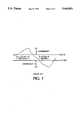
- FIG. 1is a graph of the variations in suction pressure versus time for a prior art controller of the type described above.
- prior art controllers that use separate cut-in and cut-out setpointshave an inherent dead band problem.
- the systemis not controlling the refrigeration system when the suction pressure is between the two setpoints.
- the systemis only controlled when the suction pressure has moved outside the setpoints for some period of time. This overshoot results in wide swings in suction pressure.
- the suction pressure required to maintain a desired temperaturecan be determined by referring to a pressure-temperature chart for a refrigerant. This is the only suction pressure that will maintain the desired product temperature in an ideal system. However, other factors such as evaporator superheat, refrigerant line sizing, and ambient temperature affect the relationship between the suction pressure and the temperature. As a result, one cannot depend on the calculated suction pressure value to be the optimum pressure. Prior art systems have attempted to address this problem by monitoring the temperature of the refrigerated space at predetermined intervals. If the refrigerated space is too cool, the cut-in and cut-out setpoints are increased by a predetermined incremental amount.
- the setpointsare decreased by a predetermined incremental amount. This improved control over earlier systems. However, if the load changes quickly, such as when new products are added to the refrigerated space, the incremental adjustments to the setpoints could result in a large amount of time passing before the controller matched the capacity to the load.
- the present inventionsatisfies the above described needs by providing a fuzzy logic based controller for controlling refrigeration systems.
- the controllermeasures input variables, such as case temperature, suction pressure, and the rate of change of temperature or pressure. These variables are mapped into degree-of-membership functions, and a set of fuzzy rules is applied.
- the output variablesare used to provide output signals to control the system components.
- the controller of the present inventionis able to efficiently and accurately control a refrigeration system, which is dynamic, and is neither linear nor predictable.
- the controlleris capable of using temperature as the primary control variable, thus eliminating the need to control the temperature indirectly by using suction pressure as the primary input. This approach is preferred because maintaining the desired temperature is the output that is ultimately desired from the system.
- the present inventionis also capable of switching the cooling capacity of the system to precisely match the thermal load. This eliminates the delay and inefficiencies that occurs when the compressors must be switched through several intermediate states before reaching the desired cooling capacity.
- the fuzzy logic controllerprovides the capability to vary the delay between energization state changes in response to the difference between the primary variable and the desired target, and the rate of change of the primary variable. In this manner, the controller may rapidly respond to drastic variations in the temperature or suction pressure. This also minimizes the number of energization state changes when the distance to the target variable is small, and the rate of change is small.
- FIG. 1is a graph illustrating typical suction pressure versus time characteristics of prior art systems.
- FIG. 2is a schematic representation of a refrigeration system that incorporates the fuzzy logic based controller of the present invention.
- FIG. 3is flow diagram illustrating the preferred method of operation of the system of FIG. 2.
- FIG. 4consisting of FIGS. 4a and 4b, provides graphs that illustrate the degree-of-membership functions for the temperature input and the rate of change of the temperature.
- FIG. 5consisting of FIGS. 5a and 5b, provides graphs that illustrate the degree-of-membership functions for the suction pressure input and the rate of change of the suction pressure.
- FIG. 6is a graph illustrating the degree-of-membership function for the cooling capacity output.
- FIG. 7is a graph illustrating the change in temperature versus time for the system of FIG. 2.
- FIG. 2illustrates a refrigeration system 10 that incorporates the fuzzy logic based controller 15 of the present invention.
- the system of FIG. 2is designed to maintain the desired temperatures in three refrigerated cases 20a, 20b, 20c.
- Each of the casesincludes an evaporator 25a, 25b, 25c, which must be connected to one or more compressors.
- the cases 20a, 20b, 20care divided into two suction groups. Each suction group may operate at a different temperature and is connected to its own set of compressors.
- the case 20aforms a first suction group, which is driven by compressors 30a, 30b, 30c.
- the other cases 20b, 20cconstitute a second suction group, which is driven by compressors 35a, 35b, 35c.
- the evaporator 25a in the first suction groupis connected to the compressors 30a, 30b, 30c by suction line 40.
- the evaporators 25b, 25c in the second suction groupare connected to the compressors 35a, 35b, 35c by a separate suction line 45. As discussed above, this allows each suction group to be operated at different suction pressures, which results in different operating temperatures.
- the refrigeranttravels to condensers 50a, 50b via a common high pressure discharge line 55.
- the condensers 50a, 50bwhich are connected to each other by pipe 60, are typically located on the roof of the building that houses the system, and include coils that allow the heat to be transferred from the refrigerant.
- the condensers 50a, 50bincludes a fixed speed fan 65a and a variable speed fan 65b, which force ambient outside air across the condenser coils and facilitate the transfer of heat from the condenser coils.
- the refrigerantAfter the refrigerant has passed through the condensers 50a, 50b, it travels via a discharge line drop leg 70 to a receiver 75, which acts as a reservoir for the refrigerant. From the receiver 75, the refrigerant travels to the evaporators 25a, 25b, 25c via pipe 80.
- a receiver 75acts as a reservoir for the refrigerant. From the receiver 75, the refrigerant travels to the evaporators 25a, 25b, 25c via pipe 80.
- the first suction groupis driven by three parallel compressors, which include two fixed speed compressors 30a, 30b, and one variable speed compressor 30c.
- the second suction groupis driven by two fixed speed compressor 35a, 35b, and one variable speed compressor 35c.
- the number and size of the compressors associated with each suction groupwill depend on a plurality of factors, including the desired temperature, the size of the refrigerated space, the frequency with which the case is opened and closed, etc.
- the compressors 30a, 30b, 30c, 35a, 35b, 35c and condenser fans 65a, 65bare powered by a 208 volt, three phase power source S.
- the three phase poweris applied to the compressors and condenser fans via three phase relays or contactors.
- a low voltage control signal from the controller 15 to a contractorcauses the contactor to apply the three phase power to the device by closing its contacts, or to remove power from the device by opening its contacts.
- power to the compressors 30a, 30b, 30cis controlled by contactors 85a, 85b, 85c, which receive control signals from the controller 15 via wires 90a, 90b, 90c.
- contactors 85a, 85b, 85creceive control signals from the controller 15 via wires 90a, 90b, 90c.
- the 208 volt three phase poweris first passed through an inverter 95, which changes the frequency and chops the waveform in order to cause the compressor to run at the desired speed.
- the inverteris also controlled over signals provided on wire 90c.
- the compressors 35a, 35b, 35care controlled by contactors 100a, 100b, 100c, which receive control signals from the controller 15 via wires 105a, 105b, 105c.
- An inverter 110modifies the power provided to variable speed compressor 35c via contactor 100c.
- the inverter 110is also controlled by signals provided on wire 105c.
- the fixed speed condenser fan 65areceives power through a contactor 115a, which receives control signals from controller 15 via wire 120a.
- the variable speed condenser fan 65breceives power through inverter 125 and contactor 115b, both of which receive control signal from the controller 15 via wire 120b.
- the refrigeration system 10is controlled by the fuzzy logic based controller 15.
- the controller 15is microcontroller based and employs a combination of "C" and assembly language programming.
- controller 15receives input signals from various sensors.
- the temperature of each case 20a, 20b, 20c,is monitored by temperature sensors 130a, 130b, 130c, respectively. These signals are provided to the controller 15 via wires 135a, 135b, 135c.
- the suction pressure of each suction groupis monitored by suction pressure sensors 140a, 140b, and the signals are provided to controller 15 via wires 145a, 145b.
- the controller 15also receives input signals from defrost clocks, which determine when the cases 20a, 20b, 20c will be defrosted.
- FIG. 3illustrates the preferred method 150 of operating the refrigeration system 10, which has been described above in conjunction with FIG. 2.
- the methodbegins at step 155 where the operating parameters are programmed into the system by the system manufacturer or end user. These parameters determine the operating mode and target parameters for each suction group in the system.
- the operating modedetermines whether a suction group will be controlled to maintain a target temperature or a target suction pressure.
- the target parametersindicate the desired temperatures and/or suction pressures that are to be maintained. If a suction group has more than one case, the system may be set to maintain the temperature of the coldest case.
- These parametersmay also include alarm temperatures that indicate the temperature has moved beyond certain limits.
- the operating parametersalso include the fuzzy logic algorithm that determines the control signals that are provided in response to the various input signals.
- the rules of the fuzzy logic algorithmare described more completely below. Although the operating mode and parameters must be set for each suction group, the following discussion will only consider the operation of the suction group that includes the case 20a.
- step 160the controller uses the operating parameters and input variables to determine whether the refrigeration system is to operate in the temperature or pressure mode. If the controller is programmed to operate in the temperature mode (i.e., to maintain a desired temperature), the method will advance to step 165. If the controller is programmed to operate in the pressure mode (i.e., to maintain a desired suction pressure), the method will advance to step 170.
- the present inventorbelieves that the system will typically be programmed to use temperature as the primary variable. However, even if temperature is selected as the primary variable, the system temporarily switches to the pressure mode in the following circumstances.
- the controllerwill temporarily switch to the pressure mode when a suction group enters a defrost cycle.
- the systemwill attempt to maintain the suction pressure for a predetermined period of time before reverting to the pressure mode.
- the controllerwill also switch to the pressure mode if the system is unable to maintain the desired temperature for a suction group. This typically occurs when the case temperature reaches or exceeds the alarm temperature programmed at step 155.
- the preferred systemwill switch to the pressure mode for a predetermined period of time, before attempting to return to the temperature mode. In the preferred system, this predetermined time is on the order of 15 minutes.
- step 165the controller reads the temperature that is provided by the temperature sensor 130a.
- step 175the controller determines the difference between the target temperature and the temperature from the temperature sensor 130a.
- step 180the controller uses previous temperature measurements to determine the rate of change of the temperature. Once the case temperature, difference between target temperature and case temperature, and rate of temperature change are determined, the method 150 proceeds to step 185.
- the controller"fuzzifies” the input data and applies the fuzzy logic algorithm that was provided at step 155.
- the nature and operation of the fuzzy rulesare described below in conjunction with FIGS. 4-7.
- the controllertakes the output of the fuzzy rules, and defuzzifies them to provide control signals for the compressors 30a, 30b, 30c, and for the condenser fans 65a, 65b.
- the control signalswill increase the cooling capacity of the system when the temperature in case 20a is higher than the target temperature. This is accomplished by increasing the output of compressors 30a, 30b, 30c.
- the control signalswill decrease the cooling capacity of the system when the temperature is below the target temperature by decreasing the output of compressors 30a, 30b, 30c.
- step 160the controller determines that it is to operate in the pressure mode
- the methodadvances to step 170.
- the controllerreads the suction pressure that is provided by the suction pressure sensor 140a.
- step 195the controller determines the difference between the target suction pressure and the pressure from the sensor 140a.
- step 200the controller uses previous pressure measurements to determine the rate of change of the suction pressure. Once the suction pressure, difference between target pressure and suction pressure, and rate of pressure change are determined, the method 150 proceeds to step 205.
- the controllerfuzzifies the input data and applies the fuzzy rules that were programmed at step 155.
- the nature and operation of the fuzzy rulesare described below in conjunction with FIGS. 4-7.
- the controllertakes the output of the fuzzy rules, and defuzzifies them to provide control signals for the compressors 30a, 30b, 30c, and for the condenser fans 65a, 65b.
- the control signalswill increase the cooling capacity of the system when the suction pressure is higher than the target pressure.
- the control signalswill decrease the cooling capacity of the system when the pressure is below the target pressure.
- a fuzzy logic control algorithmallows a system's operational rules to be expressed in words using linguistically stated control criteria. Unlike classical set theory, which requires that an item either be part of a set or not, fuzzy logic allows partial set membership. This allows gradual transitions between being fully a member of a set and fully not being a member of a set. In this manner, fuzzy logic allows partial truth and partial falseness. This flexibility provides a controller that is much more robust in its control algorithm and that selects the required capacity to match the thermal load without stepping through a predefined capacity table.
- the system designerIn order to design the preferred fuzzy logic refrigeration controller, the system designer first identified the system input variables and their fuzzy ranges, and established degree-of-membership functions for each range. The next step was to identify the output variables and their fuzzy ranges, and establish degree-of-membership functions for these. The designer also provided rules that map the inputs to the outputs, and determined a method of combining the outputs of various fuzzy rules into a single, executable output to the system components.
- the degree-of-membershipmay range from 0 to 1. Degree of membership functions for the preferred refrigeration system are illustrated in FIGS. 4-6, and are discussed below. After the degree-of-membership is determined, the variables are combined using the logical operators AND, OR, and NOT. The output of the AND function is the lesser of the truth values of the two variables. The output of the OR function is the greater of the truth values of the two variables. The output of the NOT function is 1 minus the truth value of the specified variable.
- fuzzy logicallows a control algorithm to be designed using imprecise terms.
- the degree of membership functionallows the system to convert the input value to a fuzzy value. As illustrated in FIG. 4a, a temperature of -12° F. would have a truth value of approximately 0.30 for the set MEDIUM POSITIVE and 0.70 for the set SMALL POSITIVE.
- a temperature of -12° F.would have a truth value of approximately 0.30 for the set MEDIUM POSITIVE and 0.70 for the set SMALL POSITIVE.
- the appropriate degree of membership for each temperaturedepends on a variety of factors, such as the target temperature, the sensitivity of the refrigerated product, etc.
- the process of converting the input variable into degree-of-membership valuesis commonly referred to as "fuzzifying.”
- fuzzy variablesare then subjected to the set of fuzzy rules that are part of the algorithm programmed into the controller.
- fuzzy rulesare part of the algorithm programmed into the controller.
- the general form for each ruleis:
- a ruleis said to "fire” if the rule responds to the fuzzy input variables.
- An outputis then determined according to the outputs of the logical rules. In many cases, more than one rule will fire, and it will be necessary to combine the actions indicated by the fuzzy output variables.
- the preferred systemuses the centroid method of combining fuzzy output variables.
- the preferred controlleralso uses selected fuzzy output values as inputs, in order to form a feedback controller.
- the present inventionemploys seven membership functions for each of the input and output variables.
- FIGS. 4a and 4billustrate the degree-of-membership functions for temperature and rate of change of the temperature.
- FIGS. 5a and 5billustrate the degree-of-membership functions for suction pressure and rate of change of the suction pressure.
- FIG. 7illustrates the degree-of-membership function for the cooling capacity output variable.
- Each of the variablesis mapped into a set of seven membership functions labeled LARGE -- NEGATIVE, MEDIUM -- NEGATIVE, SMALL -- NEGATIVE, NEAR -- TARGET, SMALL -- POSITIVE, MEDIUM -- POSITIVE, and LARGE -- POSITIVE.
- LARGE -- POSITIVEThose skilled in the art will appreciate that the number of membership functions may vary from one system to another, or from one variable to another, depending on the range of the variables and the resolution that is desired.
- the preferred systemincludes several hundred fuzzy rules. This set of rules is applied to their respective membership functions.
- An example of one rule used in the controlleris:
- the controllerBy applying each of the rules to the input variables and then defuzzifying the result, the controller provides a CAPACITY output variable between 0 and 100%. This represents the cooling capacity required for the current load.
- the controllerwould select the compressor combination that gives the closest value to 17.5 hp.
- the controllerwill attempt to equalize the runtimes on the same size compressors. If a variable speed compressor is available, the controller will select the closest combination of fixed speed compressors that is less then the required load, and then adjust the speed of the variable speed compressor until the load is precisely matched.
- the preferred systemalso uses fuzzy logic to implement an adjustable timing interval or time delay that is imposed between changes of capacity.
- the systemreduces the number of starts and stops on each compressor, and decreases the wear on the system components.
- the controllerreduces the interval when a drastic change has occurred, thereby allowing the system to rapidly correct the problem and return the temperature or pressure to the predetermined limits. For example, if the error is very small in a positive direction and the controller variable is approaching the desired target, the time delay can be relatively large. However, if the error is very small in a positive direction and the rate of change of the controlled variable is very large, the time delay must be very short in order to take action to stop the movement of the controlled variable and return it to within a predetermined range of the target.
- the controlleruses the TIME -- DELAY variable as an input, and thereby provides a feedback loop for the controller.
- TIME -- DELAYvariable
- the preferred systemis able to make rapid adjustments to system capacity when the thermal load is large or changing quickly.
- the systemis also able to reduce wear and tear on the system components by increase the time delay between energization states when the thermal load is small and is changing slowly. Those skilled in the art will appreciate that this is a significant improvement over the prior art, which implemented fixed delays and preset energization state changes regardless of the magnitude or rate of change of the thermal load.
- the controllerwill change the state of its output to match this combination. There is a small delay between each energization of a compressor and the energization of another in order to limit the inrush current being supplied by connected electrical switchgear.
- variable speed compressorIf a variable speed compressor is available, the speed of the compressor will be varied to match the load. If the speed goes to maximum and remains there for a predetermined period of time, a new compressor capacity calculation will be performed. This calculation will find the capacity that is the minimum capacity closest to the load. The compressor speed will be reduced to minimum and the outputs will take on the state of a new compressor combination.
- FIG. 7illustrates the improved temperature versus time characteristic of the preferred refrigeration system as contrasted to the prior art characteristics shown in FIG. 1.
- the curve of FIG. 7will be described in relation to demonstrative fuzzy logic rules similar to those that would be implemented in a refrigeration system.
- the particular input variables, output variables, membership functions and fuzzy ruleswill vary from one system to another depending on a variety of factors, including the size of the system, the nature of the products being refrigerated, the acceptable temperature variation, the amount of thermal input expected (e.g., how often the freezer door will be opened, or new goods will be added to the freezer).
- the output of this rulewould cause the cooling capacity of the system to be increased to a medium value which, in the system described above, may be in the range of 23-35 horsepower. This additional cooling capacity would be expected to cause the temperature to drop.
- the output of this rulewould decrease the capacity slightly in order to avoid or minimize overshoot as the temperature approaches the target.
- the capacity of the systemwould be decreased to approximately 17.5 to 29 horsepower, in order to slow the rate of change of the temperature.
- the systemhas gone into defrost, and the temperature has begun to increase dramatically.
- the preferred controllerwill switch to the pressure mode and attempt to maintain the appropriate suction pressure.
- the defrost cyclehas ended and the temperature is very high, and usually well above the alarm limits programmed into the controller. This causes the preferred controller to continue to use pressure as its control variable. At this point, the pressure will also be very high, and will not be changing very much. These inputs may cause the following rule to fire:
- This fuzzy rulecauses the capacity of the refrigeration system to be increased to its maximum amount in order to attempt to return the system to its normal operating parameters in the shortest amount of time.
- step 275the temperature has drifted to a point slight below the target, and is fairly stable. These conditions will cause the following rule to fire:
- This rulecauses the cooling capacity of the system to be decreased slightly, in order to allow the temperature in the case to rise slightly.
- the fuzzy logic based refrigeration controller of the present inventionprovides a much better control algorithm for controlling both temperatures and pressures. Because the fuzzy logic based controller is constantly controlling the system, it virtually eliminates the dead band problem associated with the prior art systems. This allows the refrigeration system to run more consistently and minimizes the temperature and pressure swing, which improves the shelf life of the refrigerated products. The controller also reduces the number of cycles and wear and tear on the compressors.
- the fuzzy logic refrigeration control system of the present inventionprovides a refrigeration control system that quickly and accurately matches the capacity of the refrigeration system to its thermal load without the inefficiencies resulting the preset capacity tables of the prior art.
- the variable time delayallows the system to quickly respond to a thermal load that is large or rapidly changing, and to minimize energization state changes when the thermal load is small and changing slowly. This is accomplished by measuring the desired input variables, determining the degree-of-membership of the inputs in predetermined functions, applying fuzzy rules to provide the desired output variables, defuzzifying the output variables to provide output signals to the system components.
- the controlleris also able to adjust the capacity of the system as the temperature or pressure approaches the target, which either eliminates or substantially reduces the amount of overshoot that occurs.
Landscapes
- Engineering & Computer Science (AREA)
- Physics & Mathematics (AREA)
- Artificial Intelligence (AREA)
- Software Systems (AREA)
- General Engineering & Computer Science (AREA)
- Thermal Sciences (AREA)
- Fuzzy Systems (AREA)
- Mathematical Physics (AREA)
- Mechanical Engineering (AREA)
- Health & Medical Sciences (AREA)
- Computer Vision & Pattern Recognition (AREA)
- Evolutionary Computation (AREA)
- Medical Informatics (AREA)
- General Physics & Mathematics (AREA)
- Automation & Control Theory (AREA)
- Devices That Are Associated With Refrigeration Equipment (AREA)
Abstract
Description
Claims (33)
Priority Applications (1)
| Application Number | Priority Date | Filing Date | Title |
|---|---|---|---|
| US08/187,448US5440891A (en) | 1994-01-26 | 1994-01-26 | Fuzzy logic based controller for cooling and refrigerating systems |
Applications Claiming Priority (1)
| Application Number | Priority Date | Filing Date | Title |
|---|---|---|---|
| US08/187,448US5440891A (en) | 1994-01-26 | 1994-01-26 | Fuzzy logic based controller for cooling and refrigerating systems |
Publications (1)
| Publication Number | Publication Date |
|---|---|
| US5440891Atrue US5440891A (en) | 1995-08-15 |
Family
ID=22689041
Family Applications (1)
| Application Number | Title | Priority Date | Filing Date |
|---|---|---|---|
| US08/187,448Expired - LifetimeUS5440891A (en) | 1994-01-26 | 1994-01-26 | Fuzzy logic based controller for cooling and refrigerating systems |
Country Status (1)
| Country | Link |
|---|---|
| US (1) | US5440891A (en) |
Cited By (70)
| Publication number | Priority date | Publication date | Assignee | Title |
|---|---|---|---|---|
| US5586443A (en)* | 1995-09-20 | 1996-12-24 | Conair Corporation | Refrigerant conservation system and method |
| US5669225A (en)* | 1996-06-27 | 1997-09-23 | York International Corporation | Variable speed control of a centrifugal chiller using fuzzy logic |
| US5734593A (en)* | 1996-04-24 | 1998-03-31 | Bei Sensors & Systems Company, Inc. | Fuzzy logic controlled cryogenic cooler |
| US5809795A (en)* | 1996-04-12 | 1998-09-22 | York International Corporation | Fuzzy logic liquid level control |
| WO1999017066A1 (en)* | 1997-09-29 | 1999-04-08 | Copeland Corporation | An adaptive control for a refrigeration system using pulse width modulated duty cycle scroll compressor |
| FR2769386A1 (en)* | 1997-10-06 | 1999-04-09 | Air Liquide | METHOD AND DEVICE FOR CONTROLLING AT LEAST TWO PRODUCTION APPARATUSES |
| FR2785062A1 (en)* | 1998-10-26 | 2000-04-28 | Air Liquide | Modular product flow producing plant, especially for nitrogen production from air, has a fuzzy logic controller for controlling treatment units of the modules |
| US6092380A (en)* | 1998-11-23 | 2000-07-25 | Delphi Technologies, Inc. | Method for regulating the cooling performance of an air conditioning system |
| US6095427A (en)* | 1999-04-22 | 2000-08-01 | Thermo King Corporation | Temperature control system and method for efficiently obtaining and maintaining the temperature in a conditioned space |
| EP1139037A1 (en)* | 2000-03-31 | 2001-10-04 | Computer Process Controls, Inc. | Method and apparatus for refrigeration system control having electronic evaporator pressure regulators |
| FR2807823A1 (en)* | 2000-04-18 | 2001-10-19 | Energie Transfert Thermique | Control of compressors in air conditioning installation, uses principal compressors operating in 'all-or-nothing' mode and a variable auxiliary compressor to fill in the steps as principal compressors are switched in or out |
| US6419454B1 (en) | 2000-06-14 | 2002-07-16 | Leo P. Christiansen | Air compressor control sequencer |
| US6516622B1 (en)* | 2000-06-13 | 2003-02-11 | Belair Technologies, Llc | Method and apparatus for variable frequency controlled compressor and fan |
| US6619061B2 (en) | 2001-12-26 | 2003-09-16 | York International Corporation | Self-tuning pull-down fuzzy logic temperature control for refrigeration systems |
| US20030230102A1 (en)* | 2002-06-12 | 2003-12-18 | Lg Electronics Inc. | Method for controlling operation of a multi-air conditioner |
| US6669102B1 (en)* | 2002-12-05 | 2003-12-30 | Lg Electronics Inc. | Method for operating air conditioner in warming mode |
| US20040003610A1 (en)* | 2002-07-03 | 2004-01-08 | Lg Electronics Inc. | Air conditioning system with two compressors and method for operating the same |
| US20050066914A1 (en)* | 2003-09-25 | 2005-03-31 | Detroit Diesel Corporation | System and method for controlling fan activation based on intake manifold air temperature and time in an egr system |
| US20050244277A1 (en)* | 2004-04-30 | 2005-11-03 | Hurst Ernest P Jr | Fixed and variable compressor system capacity control |
| US20060059926A1 (en)* | 2004-09-22 | 2006-03-23 | York International Corporation | Two-zone fuzzy logic liquid level control |
| US20060065753A1 (en)* | 2003-12-29 | 2006-03-30 | Airbus Deutschland Gmbh | Temperature control system |
| AU2005201354B2 (en)* | 1997-09-29 | 2006-12-07 | Emerson Climate Technologies, Inc. | An adaptive control for a refrigeration system using pulse width modulated duty cycle scroll compresor |
| US20070095083A1 (en)* | 2005-10-28 | 2007-05-03 | Lg Electronics Inc. | Method and apparatus for removing partial overload in an air conditioner |
| US20070240440A1 (en)* | 2006-04-12 | 2007-10-18 | Hussmann Corporation | Methods and apparatus for linearized temperature control of commercial refrigeration systems |
| US20070245753A1 (en)* | 2006-04-03 | 2007-10-25 | Daniel Landers | Refrigeration system capacity controller and method |
| US7290398B2 (en) | 2003-08-25 | 2007-11-06 | Computer Process Controls, Inc. | Refrigeration control system |
| US20080046463A1 (en)* | 2002-07-31 | 2008-02-21 | Sap Aktiengesellschaft | Integration Framework |
| AU2005202581B2 (en)* | 2000-02-29 | 2008-04-10 | Emerson Climate Technologies, Inc. | Compressor with control and protection system |
| US7594407B2 (en) | 2005-10-21 | 2009-09-29 | Emerson Climate Technologies, Inc. | Monitoring refrigerant in a refrigeration system |
| US7596959B2 (en) | 2005-10-21 | 2009-10-06 | Emerson Retail Services, Inc. | Monitoring compressor performance in a refrigeration system |
| US7644591B2 (en) | 2001-05-03 | 2010-01-12 | Emerson Retail Services, Inc. | System for remote refrigeration monitoring and diagnostics |
| US7665315B2 (en) | 2005-10-21 | 2010-02-23 | Emerson Retail Services, Inc. | Proofing a refrigeration system operating state |
| US20100125369A1 (en)* | 2008-11-17 | 2010-05-20 | Trane International, Inc. | System and Method for Defrost of an HVAC System |
| US7752853B2 (en) | 2005-10-21 | 2010-07-13 | Emerson Retail Services, Inc. | Monitoring refrigerant in a refrigeration system |
| US7752854B2 (en) | 2005-10-21 | 2010-07-13 | Emerson Retail Services, Inc. | Monitoring a condenser in a refrigeration system |
| US20100175401A1 (en)* | 2007-06-26 | 2010-07-15 | Yukihiko Taguchi | Displacement control system for a variable displacement compressor |
| US20100287964A1 (en)* | 2008-01-16 | 2010-11-18 | Masakazu Okamoto | Refrigerating apparatus |
| US7885959B2 (en) | 2005-02-21 | 2011-02-08 | Computer Process Controls, Inc. | Enterprise controller display method |
| US8157538B2 (en) | 2007-07-23 | 2012-04-17 | Emerson Climate Technologies, Inc. | Capacity modulation system for compressor and method |
| US8308455B2 (en) | 2009-01-27 | 2012-11-13 | Emerson Climate Technologies, Inc. | Unloader system and method for a compressor |
| US8473106B2 (en) | 2009-05-29 | 2013-06-25 | Emerson Climate Technologies Retail Solutions, Inc. | System and method for monitoring and evaluating equipment operating parameter modifications |
| US8495886B2 (en) | 2001-05-03 | 2013-07-30 | Emerson Climate Technologies Retail Solutions, Inc. | Model-based alarming |
| USRE44636E1 (en) | 1997-09-29 | 2013-12-10 | Emerson Climate Technologies, Inc. | Compressor capacity modulation |
| US8700444B2 (en) | 2002-10-31 | 2014-04-15 | Emerson Retail Services Inc. | System for monitoring optimal equipment operating parameters |
| US20150027139A1 (en)* | 2012-11-21 | 2015-01-29 | Liebert Corporation | Apparatus and method for subcooling control based on superheat setpoint control |
| US8964338B2 (en) | 2012-01-11 | 2015-02-24 | Emerson Climate Technologies, Inc. | System and method for compressor motor protection |
| US8974573B2 (en) | 2004-08-11 | 2015-03-10 | Emerson Climate Technologies, Inc. | Method and apparatus for monitoring a refrigeration-cycle system |
| US9121407B2 (en) | 2004-04-27 | 2015-09-01 | Emerson Climate Technologies, Inc. | Compressor diagnostic and protection system and method |
| US9140728B2 (en) | 2007-11-02 | 2015-09-22 | Emerson Climate Technologies, Inc. | Compressor sensor module |
| US9285802B2 (en) | 2011-02-28 | 2016-03-15 | Emerson Electric Co. | Residential solutions HVAC monitoring and diagnosis |
| US9310094B2 (en) | 2007-07-30 | 2016-04-12 | Emerson Climate Technologies, Inc. | Portable method and apparatus for monitoring refrigerant-cycle systems |
| US9310439B2 (en) | 2012-09-25 | 2016-04-12 | Emerson Climate Technologies, Inc. | Compressor having a control and diagnostic module |
| CN105571226A (en)* | 2014-11-03 | 2016-05-11 | 福特环球技术公司 | System and method for operating a heat pump |
| US9551504B2 (en) | 2013-03-15 | 2017-01-24 | Emerson Electric Co. | HVAC system remote monitoring and diagnosis |
| US9599118B2 (en) | 2013-04-04 | 2017-03-21 | Trane International Inc. | System and method for controlling a system that includes fixed speed and variable speed compressors |
| US9638436B2 (en) | 2013-03-15 | 2017-05-02 | Emerson Electric Co. | HVAC system remote monitoring and diagnosis |
| US9765979B2 (en) | 2013-04-05 | 2017-09-19 | Emerson Climate Technologies, Inc. | Heat-pump system with refrigerant charge diagnostics |
| US9803902B2 (en) | 2013-03-15 | 2017-10-31 | Emerson Climate Technologies, Inc. | System for refrigerant charge verification using two condenser coil temperatures |
| CN107328125A (en)* | 2017-07-07 | 2017-11-07 | 泰州职业技术学院 | A kind of helical-lobe compressor refrigeration control system and its method |
| US9823632B2 (en) | 2006-09-07 | 2017-11-21 | Emerson Climate Technologies, Inc. | Compressor data module |
| US9885507B2 (en) | 2006-07-19 | 2018-02-06 | Emerson Climate Technologies, Inc. | Protection and diagnostic module for a refrigeration system |
| CN107726683A (en)* | 2017-09-04 | 2018-02-23 | 珠海格力电器股份有限公司 | Water chilling unit and control method and device thereof |
| US10041713B1 (en) | 1999-08-20 | 2018-08-07 | Hudson Technologies, Inc. | Method and apparatus for measuring and improving efficiency in refrigeration systems |
| US10352606B2 (en) | 2012-04-27 | 2019-07-16 | Carrier Corporation | Cooling system |
| US10670316B2 (en) | 2017-06-21 | 2020-06-02 | Johnson Controls Technology Company | Compressor and fan staging in heating, ventilation, and air conditioning systems |
| CN112212471A (en)* | 2019-07-09 | 2021-01-12 | 青岛海尔空调电子有限公司 | Air conditioning system and compressor control method thereof |
| CN113093520A (en)* | 2021-03-10 | 2021-07-09 | 无锡信捷电气股份有限公司 | Fuzzy self-adaptive PID algorithm |
| US11326805B2 (en)* | 2019-03-15 | 2022-05-10 | Carrier Corporation | Control method for air conditioning system |
| US11454409B2 (en)* | 2019-03-15 | 2022-09-27 | Carrier Corporation | Failure detection method for air conditioning system |
| CN119509093A (en)* | 2024-12-31 | 2025-02-25 | 珠海格力电器股份有限公司 | Balanced control method of modular refrigeration unit and modular refrigeration unit |
Citations (10)
| Publication number | Priority date | Publication date | Assignee | Title |
|---|---|---|---|---|
| US4081691A (en)* | 1976-08-05 | 1978-03-28 | Athena Controls Inc. | Controller for a multiple stage power device having interchangeable control units |
| US4084388A (en)* | 1976-11-08 | 1978-04-18 | Honeywell Inc. | Refrigeration control system for optimum demand operation |
| US4270361A (en)* | 1979-03-14 | 1981-06-02 | Barge Michael A | Energy management controller for centrifugal water chiller |
| US4535602A (en)* | 1983-10-12 | 1985-08-20 | Richard H. Alsenz | Shift logic control apparatus for unequal capacity compressors in a refrigeration system |
| US4612776A (en)* | 1979-07-31 | 1986-09-23 | Alsenz Richard H | Method and apparatus for controlling capacity of a multiple-stage cooling system |
| US4628700A (en)* | 1979-07-31 | 1986-12-16 | Alsenz Richard H | Temperature optimizer control apparatus and method |
| US4633672A (en)* | 1985-02-19 | 1987-01-06 | Margaux Controls, Inc. | Unequal compressor refrigeration control system |
| US4825662A (en)* | 1979-07-31 | 1989-05-02 | Alsenz Richard H | Temperature responsive compressor pressure control apparatus and method |
| USRE33620E (en)* | 1987-02-09 | 1991-06-25 | Margaux, Inc. | Continuously variable capacity refrigeration system |
| US5247806A (en)* | 1990-08-20 | 1993-09-28 | Matsushita Electric Industrial Co., Ltd. | Multi-system air conditioner |
- 1994
- 1994-01-26USUS08/187,448patent/US5440891A/ennot_activeExpired - Lifetime
Patent Citations (10)
| Publication number | Priority date | Publication date | Assignee | Title |
|---|---|---|---|---|
| US4081691A (en)* | 1976-08-05 | 1978-03-28 | Athena Controls Inc. | Controller for a multiple stage power device having interchangeable control units |
| US4084388A (en)* | 1976-11-08 | 1978-04-18 | Honeywell Inc. | Refrigeration control system for optimum demand operation |
| US4270361A (en)* | 1979-03-14 | 1981-06-02 | Barge Michael A | Energy management controller for centrifugal water chiller |
| US4612776A (en)* | 1979-07-31 | 1986-09-23 | Alsenz Richard H | Method and apparatus for controlling capacity of a multiple-stage cooling system |
| US4628700A (en)* | 1979-07-31 | 1986-12-16 | Alsenz Richard H | Temperature optimizer control apparatus and method |
| US4825662A (en)* | 1979-07-31 | 1989-05-02 | Alsenz Richard H | Temperature responsive compressor pressure control apparatus and method |
| US4535602A (en)* | 1983-10-12 | 1985-08-20 | Richard H. Alsenz | Shift logic control apparatus for unequal capacity compressors in a refrigeration system |
| US4633672A (en)* | 1985-02-19 | 1987-01-06 | Margaux Controls, Inc. | Unequal compressor refrigeration control system |
| USRE33620E (en)* | 1987-02-09 | 1991-06-25 | Margaux, Inc. | Continuously variable capacity refrigeration system |
| US5247806A (en)* | 1990-08-20 | 1993-09-28 | Matsushita Electric Industrial Co., Ltd. | Multi-system air conditioner |
Cited By (156)
| Publication number | Priority date | Publication date | Assignee | Title |
|---|---|---|---|---|
| US7419365B2 (en) | 1995-06-07 | 2008-09-02 | Emerson Climate Technologies, Inc. | Compressor with capacity control |
| US7389649B2 (en) | 1995-06-07 | 2008-06-24 | Emerson Climate Technologies, Inc. | Cooling system with variable duty cycle capacity control |
| US6679072B2 (en) | 1995-06-07 | 2004-01-20 | Copeland Corporation | Diagnostic system and method for a cooling system |
| US20070022771A1 (en)* | 1995-06-07 | 2007-02-01 | Pham Hung M | Cooling system with variable capacity control |
| US6662583B2 (en) | 1995-06-07 | 2003-12-16 | Copeland Corporation | Adaptive control for a cooling system |
| US6662578B2 (en) | 1995-06-07 | 2003-12-16 | Copeland Corporation | Refrigeration system and method for controlling defrost |
| US20040123612A1 (en)* | 1995-06-07 | 2004-07-01 | Pham Hung M. | Cooling system with variable duty cycle capacity control |
| US7654098B2 (en) | 1995-06-07 | 2010-02-02 | Emerson Climate Technologies, Inc. | Cooling system with variable capacity control |
| US6047557A (en)* | 1995-06-07 | 2000-04-11 | Copeland Corporation | Adaptive control for a refrigeration system using pulse width modulated duty cycle scroll compressor |
| US6467280B2 (en) | 1995-06-07 | 2002-10-22 | Copeland Corporation | Adaptive control for a refrigeration system using pulse width modulated duty cycle scroll compressor |
| US6449972B2 (en) | 1995-06-07 | 2002-09-17 | Copeland Corporation | Adaptive control for a refrigeration system using pulse width modulated duty cycle scroll compressor |
| US6408635B1 (en) | 1995-06-07 | 2002-06-25 | Copeland Corporation | Adaptive control for a refrigeration system using pulse width modulated duty cycle scroll compressor |
| USRE42006E1 (en) | 1995-06-07 | 2010-12-28 | Emerson Climate Technologies, Inc. | Adaptive control for a refrigeration system using pulse width modulated duty cycle scroll compressor |
| US5586443A (en)* | 1995-09-20 | 1996-12-24 | Conair Corporation | Refrigerant conservation system and method |
| US5809795A (en)* | 1996-04-12 | 1998-09-22 | York International Corporation | Fuzzy logic liquid level control |
| US5734593A (en)* | 1996-04-24 | 1998-03-31 | Bei Sensors & Systems Company, Inc. | Fuzzy logic controlled cryogenic cooler |
| US5669225A (en)* | 1996-06-27 | 1997-09-23 | York International Corporation | Variable speed control of a centrifugal chiller using fuzzy logic |
| WO1997050022A1 (en)* | 1996-06-27 | 1997-12-31 | York International Corporation | Variable speed control of a centrifugal chiller using fuzzy logic |
| AU748946B2 (en)* | 1997-09-29 | 2002-06-13 | Emerson Climate Technologies, Inc. | An adaptive control for a refrigeration system using pulse width modulated duty cycle scroll compressor |
| EP1489368A3 (en)* | 1997-09-29 | 2005-06-01 | Copeland Corporation | An adaptive control for a refrigeration system using pulse width modulated duty cycle scroll compressor |
| AU2005201354B2 (en)* | 1997-09-29 | 2006-12-07 | Emerson Climate Technologies, Inc. | An adaptive control for a refrigeration system using pulse width modulated duty cycle scroll compresor |
| CN1607478B (en)* | 1997-09-29 | 2010-05-05 | 艾默生环境优化技术有限公司 | An adaptive control for a refrigeration system using pulse width modulated duty cycle scroll compressor |
| AU2005201355B2 (en)* | 1997-09-29 | 2007-04-19 | Emerson Climate Technologies, Inc. | An adaptive control for a refrigeration system using pulse width modulated duty cycle scroll compresor |
| USRE44636E1 (en) | 1997-09-29 | 2013-12-10 | Emerson Climate Technologies, Inc. | Compressor capacity modulation |
| WO1999017066A1 (en)* | 1997-09-29 | 1999-04-08 | Copeland Corporation | An adaptive control for a refrigeration system using pulse width modulated duty cycle scroll compressor |
| EP0908808A1 (en)* | 1997-10-06 | 1999-04-14 | L'air Liquide, Societe Anonyme Pour L'etude Et L'exploitation Des Procedes Georges Claude | Method and device for controling at least two production devices |
| US6519582B1 (en) | 1997-10-06 | 2003-02-11 | L'air Liquide Societe Anonyme A Directore Et Conseil De Surveillance Pour L'etude Et L'exploitation Des Procedes Georges Claude | Process and device for controlling at least two production units |
| FR2769386A1 (en)* | 1997-10-06 | 1999-04-09 | Air Liquide | METHOD AND DEVICE FOR CONTROLLING AT LEAST TWO PRODUCTION APPARATUSES |
| FR2785062A1 (en)* | 1998-10-26 | 2000-04-28 | Air Liquide | Modular product flow producing plant, especially for nitrogen production from air, has a fuzzy logic controller for controlling treatment units of the modules |
| US6290750B1 (en) | 1998-10-26 | 2001-09-18 | L'air Liquide, Societe Anonyme Pour L'etude Et L'exploitation Des Procedes Georges Claude | Production plant and process comprising several treatment steps |
| US6092380A (en)* | 1998-11-23 | 2000-07-25 | Delphi Technologies, Inc. | Method for regulating the cooling performance of an air conditioning system |
| US6095427A (en)* | 1999-04-22 | 2000-08-01 | Thermo King Corporation | Temperature control system and method for efficiently obtaining and maintaining the temperature in a conditioned space |
| US10041713B1 (en) | 1999-08-20 | 2018-08-07 | Hudson Technologies, Inc. | Method and apparatus for measuring and improving efficiency in refrigeration systems |
| AU2005202581B2 (en)* | 2000-02-29 | 2008-04-10 | Emerson Climate Technologies, Inc. | Compressor with control and protection system |
| US6601398B2 (en) | 2000-03-31 | 2003-08-05 | Computer Process Controls, Inc. | Method and apparatus for refrigeration system control having electronic evaporator pressure regulators |
| US20070022767A1 (en)* | 2000-03-31 | 2007-02-01 | Abtar Singh | Method and apparatus for refrigeration system control having electronic evaporat or pressure regulators |
| US6578374B2 (en) | 2000-03-31 | 2003-06-17 | Computer Process Controls, Inc. | Method and apparatus for refrigeration system control having electronic evaporator pressure regulators |
| AU778337B2 (en)* | 2000-03-31 | 2004-12-02 | Emerson Climate Technologies Retail Solutions, Inc. | Method and apparatus for refrigeration system control having electronic evaporator pressure regulators |
| EP1139037A1 (en)* | 2000-03-31 | 2001-10-04 | Computer Process Controls, Inc. | Method and apparatus for refrigeration system control having electronic evaporator pressure regulators |
| KR100740051B1 (en)* | 2000-03-31 | 2007-07-16 | 컴퓨터 프로세스 컨트롤스 인코포레이티드 | Method and apparatus for refrigeration system control having electronic evaporator pressure regulators |
| US6449968B1 (en) | 2000-03-31 | 2002-09-17 | Computer Process Controls, Inc. | Method and apparatus for refrigeration system control having electronic evaporator pressure regulators |
| US7134294B2 (en) | 2000-03-31 | 2006-11-14 | Computer Process Controls, Inc. | Method and apparatus for refrigeration system control having electronic evaporator pressure regulators |
| US20040016252A1 (en)* | 2000-03-31 | 2004-01-29 | Abtar Singh | Method and apparatus for refrigeration system control having electronic evaporator pressure regulators |
| US20050204759A1 (en)* | 2000-03-31 | 2005-09-22 | Abtar Singh | Method and apparatus for refrigeration system control having electronic evaporator pressure regulators |
| US6360553B1 (en) | 2000-03-31 | 2002-03-26 | Computer Process Controls, Inc. | Method and apparatus for refrigeration system control having electronic evaporator pressure regulators |
| US6983618B2 (en) | 2000-03-31 | 2006-01-10 | Computer Process Controls, Inc. | Method and apparatus for refrigeration system control having electronic evaporator pressure regulators |
| FR2807823A1 (en)* | 2000-04-18 | 2001-10-19 | Energie Transfert Thermique | Control of compressors in air conditioning installation, uses principal compressors operating in 'all-or-nothing' mode and a variable auxiliary compressor to fill in the steps as principal compressors are switched in or out |
| US20050086959A1 (en)* | 2000-06-13 | 2005-04-28 | Wilson James J. | Method and apparatus for variable frequency controlled compressor and fan |
| US6516622B1 (en)* | 2000-06-13 | 2003-02-11 | Belair Technologies, Llc | Method and apparatus for variable frequency controlled compressor and fan |
| US6817198B2 (en) | 2000-06-13 | 2004-11-16 | Belair Technologies, Llc | Method and apparatus for variable frequency controlled compressor and fan |
| US6419454B1 (en) | 2000-06-14 | 2002-07-16 | Leo P. Christiansen | Air compressor control sequencer |
| US8065886B2 (en) | 2001-05-03 | 2011-11-29 | Emerson Retail Services, Inc. | Refrigeration system energy monitoring and diagnostics |
| US8316658B2 (en) | 2001-05-03 | 2012-11-27 | Emerson Climate Technologies Retail Solutions, Inc. | Refrigeration system energy monitoring and diagnostics |
| US7644591B2 (en) | 2001-05-03 | 2010-01-12 | Emerson Retail Services, Inc. | System for remote refrigeration monitoring and diagnostics |
| US8495886B2 (en) | 2001-05-03 | 2013-07-30 | Emerson Climate Technologies Retail Solutions, Inc. | Model-based alarming |
| US6619061B2 (en) | 2001-12-26 | 2003-09-16 | York International Corporation | Self-tuning pull-down fuzzy logic temperature control for refrigeration systems |
| US20030230102A1 (en)* | 2002-06-12 | 2003-12-18 | Lg Electronics Inc. | Method for controlling operation of a multi-air conditioner |
| US6766653B2 (en)* | 2002-06-12 | 2004-07-27 | Lg Electronics Inc. | Method for controlling operation of a multi-air conditioner |
| US6874326B2 (en)* | 2002-07-03 | 2005-04-05 | Lg Electronics Inc. | Air conditioning system with two compressors and method for operating the same |
| US20040003610A1 (en)* | 2002-07-03 | 2004-01-08 | Lg Electronics Inc. | Air conditioning system with two compressors and method for operating the same |
| US20080046463A1 (en)* | 2002-07-31 | 2008-02-21 | Sap Aktiengesellschaft | Integration Framework |
| US7762459B2 (en)* | 2002-07-31 | 2010-07-27 | Sap Aktiengesellschaft | Integration framework |
| US8700444B2 (en) | 2002-10-31 | 2014-04-15 | Emerson Retail Services Inc. | System for monitoring optimal equipment operating parameters |
| US6669102B1 (en)* | 2002-12-05 | 2003-12-30 | Lg Electronics Inc. | Method for operating air conditioner in warming mode |
| US7290398B2 (en) | 2003-08-25 | 2007-11-06 | Computer Process Controls, Inc. | Refrigeration control system |
| US20050066914A1 (en)* | 2003-09-25 | 2005-03-31 | Detroit Diesel Corporation | System and method for controlling fan activation based on intake manifold air temperature and time in an egr system |
| US6880497B1 (en) | 2003-09-25 | 2005-04-19 | Detroit Diesel Corporation | System and method for controlling fan activation based on intake manifold air temperature and time in an EGR system |
| US20060065753A1 (en)* | 2003-12-29 | 2006-03-30 | Airbus Deutschland Gmbh | Temperature control system |
| US7337623B2 (en)* | 2003-12-29 | 2008-03-04 | Airbus Deutschland Gmbh | Fuzzy-logic based controller to regulate aircraft temperature |
| US9121407B2 (en) | 2004-04-27 | 2015-09-01 | Emerson Climate Technologies, Inc. | Compressor diagnostic and protection system and method |
| US9669498B2 (en) | 2004-04-27 | 2017-06-06 | Emerson Climate Technologies, Inc. | Compressor diagnostic and protection system and method |
| US10335906B2 (en) | 2004-04-27 | 2019-07-02 | Emerson Climate Technologies, Inc. | Compressor diagnostic and protection system and method |
| EP1751430B1 (en) | 2004-04-30 | 2017-07-05 | Computer Process Controls, Inc. | Fixed and variable compressor system capacity control |
| US8287230B2 (en) | 2004-04-30 | 2012-10-16 | Emerson Climate Technologies Retail Solutions, Inc. | Fixed and variable compressor system capacity control |
| US20050244277A1 (en)* | 2004-04-30 | 2005-11-03 | Hurst Ernest P Jr | Fixed and variable compressor system capacity control |
| US7918655B2 (en) | 2004-04-30 | 2011-04-05 | Computer Process Controls, Inc. | Fixed and variable compressor system capacity control |
| US20110008181A1 (en)* | 2004-04-30 | 2011-01-13 | Computer Process Controls, Inc. | Fixed and variable compressor system capacity control |
| US10558229B2 (en) | 2004-08-11 | 2020-02-11 | Emerson Climate Technologies Inc. | Method and apparatus for monitoring refrigeration-cycle systems |
| US8974573B2 (en) | 2004-08-11 | 2015-03-10 | Emerson Climate Technologies, Inc. | Method and apparatus for monitoring a refrigeration-cycle system |
| US9086704B2 (en) | 2004-08-11 | 2015-07-21 | Emerson Climate Technologies, Inc. | Method and apparatus for monitoring a refrigeration-cycle system |
| US9304521B2 (en) | 2004-08-11 | 2016-04-05 | Emerson Climate Technologies, Inc. | Air filter monitoring system |
| US9023136B2 (en) | 2004-08-11 | 2015-05-05 | Emerson Climate Technologies, Inc. | Method and apparatus for monitoring a refrigeration-cycle system |
| US9021819B2 (en) | 2004-08-11 | 2015-05-05 | Emerson Climate Technologies, Inc. | Method and apparatus for monitoring a refrigeration-cycle system |
| US9017461B2 (en) | 2004-08-11 | 2015-04-28 | Emerson Climate Technologies, Inc. | Method and apparatus for monitoring a refrigeration-cycle system |
| US9046900B2 (en) | 2004-08-11 | 2015-06-02 | Emerson Climate Technologies, Inc. | Method and apparatus for monitoring refrigeration-cycle systems |
| US9081394B2 (en) | 2004-08-11 | 2015-07-14 | Emerson Climate Technologies, Inc. | Method and apparatus for monitoring a refrigeration-cycle system |
| US9690307B2 (en) | 2004-08-11 | 2017-06-27 | Emerson Climate Technologies, Inc. | Method and apparatus for monitoring refrigeration-cycle systems |
| US20100030385A1 (en)* | 2004-09-22 | 2010-02-04 | York International Corporation | Two-zone fuzzy logic liquid level control |
| US7621141B2 (en) | 2004-09-22 | 2009-11-24 | York International Corporation | Two-zone fuzzy logic liquid level control |
| US7784295B2 (en) | 2004-09-22 | 2010-08-31 | York International Corporation | Two-zone fuzzy logic liquid level control |
| US20060059926A1 (en)* | 2004-09-22 | 2006-03-23 | York International Corporation | Two-zone fuzzy logic liquid level control |
| US7885959B2 (en) | 2005-02-21 | 2011-02-08 | Computer Process Controls, Inc. | Enterprise controller display method |
| US7885961B2 (en) | 2005-02-21 | 2011-02-08 | Computer Process Controls, Inc. | Enterprise control and monitoring system and method |
| US7752854B2 (en) | 2005-10-21 | 2010-07-13 | Emerson Retail Services, Inc. | Monitoring a condenser in a refrigeration system |
| US7752853B2 (en) | 2005-10-21 | 2010-07-13 | Emerson Retail Services, Inc. | Monitoring refrigerant in a refrigeration system |
| US7665315B2 (en) | 2005-10-21 | 2010-02-23 | Emerson Retail Services, Inc. | Proofing a refrigeration system operating state |
| US7596959B2 (en) | 2005-10-21 | 2009-10-06 | Emerson Retail Services, Inc. | Monitoring compressor performance in a refrigeration system |
| US7594407B2 (en) | 2005-10-21 | 2009-09-29 | Emerson Climate Technologies, Inc. | Monitoring refrigerant in a refrigeration system |
| US20070095083A1 (en)* | 2005-10-28 | 2007-05-03 | Lg Electronics Inc. | Method and apparatus for removing partial overload in an air conditioner |
| US7861546B2 (en)* | 2006-04-03 | 2011-01-04 | Computer Process Controls, Inc. | Refrigeration system capacity controller and method |
| US20070245753A1 (en)* | 2006-04-03 | 2007-10-25 | Daniel Landers | Refrigeration system capacity controller and method |
| US7797957B2 (en) | 2006-04-12 | 2010-09-21 | Hussmann Corporation | Methods and apparatus for linearized temperature control of commercial refrigeration systems |
| US20070240440A1 (en)* | 2006-04-12 | 2007-10-18 | Hussmann Corporation | Methods and apparatus for linearized temperature control of commercial refrigeration systems |
| US9885507B2 (en) | 2006-07-19 | 2018-02-06 | Emerson Climate Technologies, Inc. | Protection and diagnostic module for a refrigeration system |
| US9823632B2 (en) | 2006-09-07 | 2017-11-21 | Emerson Climate Technologies, Inc. | Compressor data module |
| US20100175401A1 (en)* | 2007-06-26 | 2010-07-15 | Yukihiko Taguchi | Displacement control system for a variable displacement compressor |
| DE112008001709B4 (en) | 2007-06-26 | 2018-12-27 | Sanden Holdings Corporation | Displacement control system for a variable displacement compressor |
| US8807961B2 (en) | 2007-07-23 | 2014-08-19 | Emerson Climate Technologies, Inc. | Capacity modulation system for compressor and method |
| US8157538B2 (en) | 2007-07-23 | 2012-04-17 | Emerson Climate Technologies, Inc. | Capacity modulation system for compressor and method |
| US9310094B2 (en) | 2007-07-30 | 2016-04-12 | Emerson Climate Technologies, Inc. | Portable method and apparatus for monitoring refrigerant-cycle systems |
| US10352602B2 (en) | 2007-07-30 | 2019-07-16 | Emerson Climate Technologies, Inc. | Portable method and apparatus for monitoring refrigerant-cycle systems |
| US9140728B2 (en) | 2007-11-02 | 2015-09-22 | Emerson Climate Technologies, Inc. | Compressor sensor module |
| US9194894B2 (en) | 2007-11-02 | 2015-11-24 | Emerson Climate Technologies, Inc. | Compressor sensor module |
| US10458404B2 (en) | 2007-11-02 | 2019-10-29 | Emerson Climate Technologies, Inc. | Compressor sensor module |
| US20100287964A1 (en)* | 2008-01-16 | 2010-11-18 | Masakazu Okamoto | Refrigerating apparatus |
| US20100125369A1 (en)* | 2008-11-17 | 2010-05-20 | Trane International, Inc. | System and Method for Defrost of an HVAC System |
| US8417386B2 (en)* | 2008-11-17 | 2013-04-09 | Trane International Inc. | System and method for defrost of an HVAC system |
| US8308455B2 (en) | 2009-01-27 | 2012-11-13 | Emerson Climate Technologies, Inc. | Unloader system and method for a compressor |
| US9395711B2 (en) | 2009-05-29 | 2016-07-19 | Emerson Climate Technologies Retail Solutions, Inc. | System and method for monitoring and evaluating equipment operating parameter modifications |
| US8473106B2 (en) | 2009-05-29 | 2013-06-25 | Emerson Climate Technologies Retail Solutions, Inc. | System and method for monitoring and evaluating equipment operating parameter modifications |
| US8761908B2 (en) | 2009-05-29 | 2014-06-24 | Emerson Climate Technologies Retail Solutions, Inc. | System and method for monitoring and evaluating equipment operating parameter modifications |
| US9285802B2 (en) | 2011-02-28 | 2016-03-15 | Emerson Electric Co. | Residential solutions HVAC monitoring and diagnosis |
| US10234854B2 (en) | 2011-02-28 | 2019-03-19 | Emerson Electric Co. | Remote HVAC monitoring and diagnosis |
| US9703287B2 (en) | 2011-02-28 | 2017-07-11 | Emerson Electric Co. | Remote HVAC monitoring and diagnosis |
| US10884403B2 (en) | 2011-02-28 | 2021-01-05 | Emerson Electric Co. | Remote HVAC monitoring and diagnosis |
| US9590413B2 (en) | 2012-01-11 | 2017-03-07 | Emerson Climate Technologies, Inc. | System and method for compressor motor protection |
| US9876346B2 (en) | 2012-01-11 | 2018-01-23 | Emerson Climate Technologies, Inc. | System and method for compressor motor protection |
| US8964338B2 (en) | 2012-01-11 | 2015-02-24 | Emerson Climate Technologies, Inc. | System and method for compressor motor protection |
| US10352606B2 (en) | 2012-04-27 | 2019-07-16 | Carrier Corporation | Cooling system |
| US9310439B2 (en) | 2012-09-25 | 2016-04-12 | Emerson Climate Technologies, Inc. | Compressor having a control and diagnostic module |
| US9762168B2 (en) | 2012-09-25 | 2017-09-12 | Emerson Climate Technologies, Inc. | Compressor having a control and diagnostic module |
| US10174977B2 (en)* | 2012-11-21 | 2019-01-08 | Vertiv Corporation | Apparatus and method for subcooling control based on superheat setpoint control |
| US20150027139A1 (en)* | 2012-11-21 | 2015-01-29 | Liebert Corporation | Apparatus and method for subcooling control based on superheat setpoint control |
| US10775084B2 (en) | 2013-03-15 | 2020-09-15 | Emerson Climate Technologies, Inc. | System for refrigerant charge verification |
| US9551504B2 (en) | 2013-03-15 | 2017-01-24 | Emerson Electric Co. | HVAC system remote monitoring and diagnosis |
| US9803902B2 (en) | 2013-03-15 | 2017-10-31 | Emerson Climate Technologies, Inc. | System for refrigerant charge verification using two condenser coil temperatures |
| US10488090B2 (en) | 2013-03-15 | 2019-11-26 | Emerson Climate Technologies, Inc. | System for refrigerant charge verification |
| US10274945B2 (en) | 2013-03-15 | 2019-04-30 | Emerson Electric Co. | HVAC system remote monitoring and diagnosis |
| US9638436B2 (en) | 2013-03-15 | 2017-05-02 | Emerson Electric Co. | HVAC system remote monitoring and diagnosis |
| US20170191475A1 (en)* | 2013-04-04 | 2017-07-06 | Trane International Inc. | System and method for controlling a system that includes fixed speed and variable speed compressors |
| US11092151B2 (en)* | 2013-04-04 | 2021-08-17 | Trane International Inc. | System and method for controlling a system that includes fixed speed and variable speed compressors |
| US9599118B2 (en) | 2013-04-04 | 2017-03-21 | Trane International Inc. | System and method for controlling a system that includes fixed speed and variable speed compressors |
| US10443863B2 (en) | 2013-04-05 | 2019-10-15 | Emerson Climate Technologies, Inc. | Method of monitoring charge condition of heat pump system |
| US9765979B2 (en) | 2013-04-05 | 2017-09-19 | Emerson Climate Technologies, Inc. | Heat-pump system with refrigerant charge diagnostics |
| US10060636B2 (en) | 2013-04-05 | 2018-08-28 | Emerson Climate Technologies, Inc. | Heat pump system with refrigerant charge diagnostics |
| CN105571226A (en)* | 2014-11-03 | 2016-05-11 | 福特环球技术公司 | System and method for operating a heat pump |
| CN105571226B (en)* | 2014-11-03 | 2020-02-28 | 福特环球技术公司 | System and method for operating a heat pump |
| US10670316B2 (en) | 2017-06-21 | 2020-06-02 | Johnson Controls Technology Company | Compressor and fan staging in heating, ventilation, and air conditioning systems |
| CN107328125A (en)* | 2017-07-07 | 2017-11-07 | 泰州职业技术学院 | A kind of helical-lobe compressor refrigeration control system and its method |
| CN107726683A (en)* | 2017-09-04 | 2018-02-23 | 珠海格力电器股份有限公司 | Water chilling unit and control method and device thereof |
| US11326805B2 (en)* | 2019-03-15 | 2022-05-10 | Carrier Corporation | Control method for air conditioning system |
| US11454409B2 (en)* | 2019-03-15 | 2022-09-27 | Carrier Corporation | Failure detection method for air conditioning system |
| CN112212471A (en)* | 2019-07-09 | 2021-01-12 | 青岛海尔空调电子有限公司 | Air conditioning system and compressor control method thereof |
| CN112212471B (en)* | 2019-07-09 | 2022-09-16 | 青岛海尔空调电子有限公司 | Air conditioning system and compressor control method thereof |
| CN113093520A (en)* | 2021-03-10 | 2021-07-09 | 无锡信捷电气股份有限公司 | Fuzzy self-adaptive PID algorithm |
| CN119509093A (en)* | 2024-12-31 | 2025-02-25 | 珠海格力电器股份有限公司 | Balanced control method of modular refrigeration unit and modular refrigeration unit |
Similar Documents
| Publication | Publication Date | Title |
|---|---|---|
| US5440891A (en) | Fuzzy logic based controller for cooling and refrigerating systems | |
| JP2634095B2 (en) | Refrigerator control device | |
| US5460009A (en) | Refrigeration system and method | |
| EP1980805B1 (en) | A method for controlling a refrigeration system | |
| CA2409539C (en) | Methods and apparatus for controlling compressor speed | |
| KR100351210B1 (en) | Cooling device and method of operation thereof | |
| US7942014B2 (en) | Reduced energy refrigerator defrost method and apparatus | |
| US6606870B2 (en) | Deterministic refrigerator defrost method and apparatus | |
| US6779353B2 (en) | Sealed system multiple speed compressor and fan control | |
| AU2005212639B9 (en) | A refrigerator and a method for controlling variable cooling capacity thereof | |
| EP1398584B1 (en) | Method for controlling a multiple cooling compartment refrigerator, and refrigerator using such method | |
| US10337768B2 (en) | Methods for controlling a compressor with double suction for refrigeration systems | |
| JPH0833244B2 (en) | Overheat temperature controller | |
| EP1318365B1 (en) | Method of controlling a variable cooling capacity compressor and refrigerator or freezer controlled by such method | |
| KR102469645B1 (en) | Variable speed condensing unit, self-adaptive capacity adjustment method, storage medium and control unit | |
| US7757501B2 (en) | Method for controlling a refrigerator appliance | |
| Silveira et al. | Least power point tracking (LPPT) control for refrigeration systems running with variable-speed compressors | |
| EP2034260B1 (en) | Method for controlling a refrigeration appliance and an appliance using such method | |
| KR20180135398A (en) | Refrigerator and method for controlling the same | |
| JPH0735421A (en) | Vapor compressing type refrigerating machine | |
| JPH056108B2 (en) | ||
| KR100452994B1 (en) | Control method for refrigeration system | |
| JPH02217753A (en) | Control of refrigerant flow rate controller | |
| CN120684831A (en) | Electronic expansion valve adjusting method, device, equipment and storage medium | |
| CN119665539A (en) | A control method for refrigerator to realize intelligent frost and reduce energy consumption by using PID control |
Legal Events
| Date | Code | Title | Description |
|---|---|---|---|
| STCF | Information on status: patent grant | Free format text:PATENTED CASE | |
| AS | Assignment | Owner name:JOHNSON CONTROLS, INC., WISCONSIN Free format text:ASSIGNMENT OF ASSIGNORS INTEREST;ASSIGNORS:HINDMON, JAMES O., JR.;HINDMON, PHILLIP G., SR.;REEL/FRAME:008907/0772 Effective date:19970228 | |
| AS | Assignment | Owner name:JOHNSON CONTROLS TECHNOLOGY COMPANY, MICHIGAN Free format text:ASSIGNMENT OF ASSIGNORS INTEREST;ASSIGNOR:JOHNSON CONTROLS, INC.;REEL/FRAME:009472/0882 Effective date:19980618 | |
| FEPP | Fee payment procedure | Free format text:PAT HLDR NO LONGER CLAIMS SMALL ENT STAT AS INDIV INVENTOR (ORIGINAL EVENT CODE: LSM1); ENTITY STATUS OF PATENT OWNER: LARGE ENTITY | |
| FPAY | Fee payment | Year of fee payment:4 | |
| FEPP | Fee payment procedure | Free format text:PAYER NUMBER DE-ASSIGNED (ORIGINAL EVENT CODE: RMPN); ENTITY STATUS OF PATENT OWNER: LARGE ENTITY Free format text:PAYOR NUMBER ASSIGNED (ORIGINAL EVENT CODE: ASPN); ENTITY STATUS OF PATENT OWNER: LARGE ENTITY | |
| FPAY | Fee payment | Year of fee payment:8 | |
| FPAY | Fee payment | Year of fee payment:12 |