US5440556A - Low power isochronous networking mode - Google Patents
Low power isochronous networking modeDownload PDFInfo
- Publication number
- US5440556A US5440556AUS08/146,723US14672393AUS5440556AUS 5440556 AUS5440556 AUS 5440556AUS 14672393 AUS14672393 AUS 14672393AUS 5440556 AUS5440556 AUS 5440556A
- Authority
- US
- United States
- Prior art keywords
- node
- transceiver
- transmitting
- data
- pulse
- Prior art date
- Legal status (The legal status is an assumption and is not a legal conclusion. Google has not performed a legal analysis and makes no representation as to the accuracy of the status listed.)
- Expired - Lifetime
Links
- 230000006855networkingEffects0.000title1
- 230000001360synchronised effectEffects0.000claimsabstractdescription6
- 230000005540biological transmissionEffects0.000claimsdescription41
- 238000012546transferMethods0.000claimsdescription16
- 238000000034methodMethods0.000claims9
- 230000008878couplingEffects0.000claims2
- 238000010168coupling processMethods0.000claims2
- 238000005859coupling reactionMethods0.000claims2
- 230000003111delayed effectEffects0.000claims2
- 238000004891communicationMethods0.000abstractdescription14
- 239000000872bufferSubstances0.000description23
- 238000010586diagramMethods0.000description11
- 238000012423maintenanceMethods0.000description10
- 230000001934delayEffects0.000description7
- 230000011664signalingEffects0.000description6
- 238000001514detection methodMethods0.000description5
- 230000000977initiatory effectEffects0.000description4
- 239000000835fiberSubstances0.000description3
- 230000006870functionEffects0.000description3
- 238000005259measurementMethods0.000description3
- 230000008901benefitEffects0.000description2
- 238000006243chemical reactionMethods0.000description2
- 239000000284extractSubstances0.000description2
- 238000009432framingMethods0.000description2
- 238000012986modificationMethods0.000description2
- 230000004048modificationEffects0.000description2
- 230000009471actionEffects0.000description1
- 230000001174ascending effectEffects0.000description1
- 230000003139buffering effectEffects0.000description1
- 230000001419dependent effectEffects0.000description1
- 230000007246mechanismEffects0.000description1
- 230000000644propagated effectEffects0.000description1
- 230000000630rising effectEffects0.000description1
- 230000007704transitionEffects0.000description1
Images


Classifications
- H—ELECTRICITY
- H04—ELECTRIC COMMUNICATION TECHNIQUE
- H04L—TRANSMISSION OF DIGITAL INFORMATION, e.g. TELEGRAPHIC COMMUNICATION
- H04L12/00—Data switching networks
- H04L12/28—Data switching networks characterised by path configuration, e.g. LAN [Local Area Networks] or WAN [Wide Area Networks]
- H04L12/44—Star or tree networks
- H—ELECTRICITY
- H04—ELECTRIC COMMUNICATION TECHNIQUE
- H04L—TRANSMISSION OF DIGITAL INFORMATION, e.g. TELEGRAPHIC COMMUNICATION
- H04L12/00—Data switching networks
- H04L12/64—Hybrid switching systems
- H—ELECTRICITY
- H04—ELECTRIC COMMUNICATION TECHNIQUE
- H04L—TRANSMISSION OF DIGITAL INFORMATION, e.g. TELEGRAPHIC COMMUNICATION
- H04L12/00—Data switching networks
- H04L12/64—Hybrid switching systems
- H04L12/6418—Hybrid transport
- H—ELECTRICITY
- H04—ELECTRIC COMMUNICATION TECHNIQUE
- H04L—TRANSMISSION OF DIGITAL INFORMATION, e.g. TELEGRAPHIC COMMUNICATION
- H04L12/00—Data switching networks
- H04L12/64—Hybrid switching systems
- H04L12/6418—Hybrid transport
- H04L2012/6432—Topology
- H04L2012/6437—Ring
- H—ELECTRICITY
- H04—ELECTRIC COMMUNICATION TECHNIQUE
- H04L—TRANSMISSION OF DIGITAL INFORMATION, e.g. TELEGRAPHIC COMMUNICATION
- H04L12/00—Data switching networks
- H04L12/64—Hybrid switching systems
- H04L12/6418—Hybrid transport
- H04L2012/6445—Admission control
- H04L2012/6448—Medium Access Control [MAC]
- H—ELECTRICITY
- H04—ELECTRIC COMMUNICATION TECHNIQUE
- H04L—TRANSMISSION OF DIGITAL INFORMATION, e.g. TELEGRAPHIC COMMUNICATION
- H04L12/00—Data switching networks
- H04L12/64—Hybrid switching systems
- H04L12/6418—Hybrid transport
- H04L2012/6445—Admission control
- H04L2012/6459—Multiplexing, e.g. TDMA, CDMA
Definitions
- the present inventionrelates to a data communication network, such as a local area network or wide area network, and in particular to a network for transferring isochronous data.
- Isochronous datacan generally be described as data which is non-packetized and of indeterminate, potentially continuous duration.
- isochronous data sourcesinclude video cameras, which output a substantially continuous stream of data representing images and associated sounds, and telephones, which output a substantially continuous stream of voice data.
- An example of an isochronous data sinkis a video monitor which receives a substantially continuous stream of video data for display.
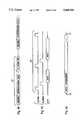
- FIG. 1Aschematically depicts isochronous data transfer.
- the data transferis first initiated, such as by initiating a telephone conversation or beginning a video camera transmission 12. After initiating the data transfer, transmission of the data is provided substantially continuously for an indeterminate period, until termination of the telephone conversation or video transmission 14. Every bit transferred need not necessarily represent a data bit. "Housekeeping" bits to control destination and timing may be also transferred. Furthermore, the data being transferred may comprise "Null" data such as silence during a telephone conversation or transfer of a blank video image.
- FDDI-IIFiber Distributed Data Interface-I
- the receivers at both ends of the associated network linkuse a cycle template to enable the exchange of isochronous data.
- the cycle templatecontinues to be exchanged even when the template contains no data and no isochronous communications are in progress.
- This continuous transmittal of data in the isochronous data pathrequires the continual expenditure of network transmitter and receiver power. Power consumption directly influences the cost of operating the device and is of particular importance if the network component is battery driven. For example, if the network device is a lap top computer, the useful operating life of the device is a direct function of battery life.
- PBX adapter cardfor a person computer.
- Several star-topology systemscan be connected by inter-connection of the hubs, for example, in a ring structure. Multiplexed data arriving at the hub is de-multiplexed to separate the isochronous-source data, the non-isochronous-source data and D channel and M channel information.
- the non-isochronous-source datacan be provided to hub circuitry specialized for handling the non-isochronous data stream.
- circuitry in the hubconverts the separated non-isochronous data stream into a form substantially similar to the form available over previous non-isochronous networks.
- the hubconverts the separated non-isochronous data to a form handled by standard Ethernet hub repeater circuitry.
- the hub-node systemincludes a means for entering a low power consumption mode during periods of no isochronous data transfer.
- the low power sequenceis initiated from either end of the connection by the signaling of a low power request through, for example, maintenance bits.
- the receiving endfilters these bits and checks that the request is received consistently in multiple consecutive frames before recognizing and acknowledging the request. After detecting the filtered acknowledge, the requesting device terminates cycle transmission at the end of the current cycle, where the cycle start indicator would have occurred if the cycle template had been running.
- the receiving endUpon detecting the loss of cycle transmission, the receiving end terminates its cycle transmission and begins transmission of pulses every 125 us.
- the receivers at both ends of the linkuse the presence of the pulses to indicate that the node at the far end of the link is still connected. It can also use the pulse as an event to maintain synchronization to the 8 kHz network frame rate.
- the hub-node systemincludes delay circuitry to compensate for cycle misalignments caused by system cabling.
- the hubtimes the delay between the transmission of the pulse and the arrival of the received pulse.
- the hubthus senses the adjustment necessary and outputs a control signal to the node.
- a delay circuitstores the delay value and delays the start of the cycle reference provided to the node transmitter.
- the node transmitterthus outputs link pulses that arrive at the hub coincident with the beginning of a cycle thereby minimizing data skew.
- the node delay circuitrycomprises a latch controlled by the hub.
- the latchtriggers when the pulse is provided to the node transmitter and thereby aligns the transmissions as desired.
- FIG. 1Ais a timing chart of an isochronous data transmission
- FIG. 1Bis a timing chart for a packetized data transmission
- FIG. 1Cis a timing chart for a token ring data transfer
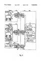
- FIG. 2Ais a diagram of a star and ring topology communication system according to an embodiment of the present invention.
- FIG. 2Bis a diagram of a star and ring topology communication system having multiple isochronous circuitry within a single hub according to an embodiment of the present invention
- FIG. 2Cis a diagram of a tree topology communication system according to an embodiment of the present invention.
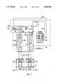
- FIG. 3is a communication system configured according to an embodiment of the present invention.
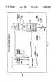
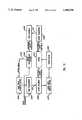
- FIG. 4is a block diagram of circuitry according to an embodiment of the present invention.
- FIG. 5is a block diagram of hub receiver circuitry according to an embodiment of the present invention.
- FIG. 6is a block diagram of a receive interface for non-isochronous data according to an embodiment of the present invention.
- FIG. 7is a diagram of a receive interface for isochronous data and associated hub circuitry according to an embodiment of the present invention.
- FIG. 8is a block diagram of a hub transmit interface for non-isochronous data according to an embodiment of the present invention.
- FIG. 9is a block diagram of a hub transmitter interface for non-isochronous data according to an embodiment of the present invention.
- FIG. 10is a flow chart of low power mode operations according to an embodiment of the present invention.
- FIG. 11is a timing chart for coordinating data transfers according to an embodiment of the present invention.
- FIG. 12is a block diagram of node circuitry having a delay circuit according to an embodiment of the present invention.
- Table Iis a tabulation of a time division multiplexing scheme for multiplexing data streams according to an embodiment of the present invention.
- Table IIlists a form of four/five encoding according to an embodiment of the present invention.
- FIGS. 2A, 2B or 2CSuch a system is shown in FIGS. 2A, 2B or 2C.
- the hubsare connected in a ring-topology with first hub 44a sending data to the second hub 44b, the second hub 44b sending data to the third hub 44c, the third hub sending data back to the first hub 44a via a cycle generator and latency adjustment circuitry.
- the inter-hub connectionsare over a Time Slot Interchange (TSI) ring 58f.
- TSITime Slot Interchange
- an FDDI-II systemcan be used as the TSI ring 58f.
- FIG. 2Bshows hubs 44a, 44b and 44c arranged in a star and ring topology having multiple isochronous circuitry within a single hub.
- FIG. 2Cshows a tree topology communication system.
- the parent hub 44aconnects to a high bandwidth backbone.
- Hub 44boperates as a child hub of parent hub 44a and is attached at port 2 of hub 44a.
- Child hub 44ccascades from child hub 44b.
- the star and ring topologyincludes a plurality of nodes 42a, 42b, 42c attached to a single hub operating on the high bandwidth bus.
- the exact number of nodesvaries depending on the data transmission needs and objectives of the system.
- Each of the nodes 42a-42ccan include various types of sources and sinks such as strictly isochronous sources and sinks, strictly non-isochronous sources/sinks or both isochronous and non-isochronous sources and sinks.
- Data linkscomprising physical data transmission media, such as one-way twisted pair wires 46a-46r, couple each node to one of hubs 44a-44c.
- FIG. 3shows hub 44a and associated nodes 42a-42c in greater detail.
- FIG. 3may, by itself, form a complete star topology system.
- Each node 42a, 42b, 42cincludes circuitry 50a, 50b, 50c.
- Circuitry 50a-ctransmits data using transmitters 78a, 78b, 78c, for conversion to a form suitable for transmission onto the physical media 46a, 46c, 46e; and receives signals from the physical media 46b, 46d, 46f using receivers 79a, 79b, 79c for conversion to a form suitable for use by the data sinks.
- Hub 44aincludes circuitry 54a, 54b, 54c for receiving data from the physical media 46a, 46c, 46e; separating the isochronous-sourced data from the non-isochronous-sourced data and the D channel and maintenance channel data; and converting separated data into a form suitable for handling by downstream hub circuitry 56.
- the separated isochronous-sourced datais provided to isochronous switching circuitry such as a time slot interchange controller 58 for placing the data on a TSI bus so that it can be transported to and retrieved by other equivalent circuitry 54a-54c in the hub for transmission to various destination nodes 42a-42c to other hubs.
- the separated non-isochronous datais provided to circuitry 60 configured to convey the non-isochronous data for transmission to destination nodes 42a, 42b, 42c.
- the hub circuitry 60can be a standard Ethernet repeater processor. In this way, the system can be at least partially backwards-compatible with previous Ethernet hub systems.
- the D channel and maintenance datais provided to a signaling processor 62.
- Signaling processor 62performs various maintenance and control functions such as identifying and alerting users of error conditions, and setting up requested connections, i.e. source/destination paths e.g. by communicating with the isochronous and non-isochronous controllers 58, 60, e.g. over data path 64.
- the isochronous controller 58can be a data exchanger e.g. on isochronous switching device such as that described in commonly assigned application Ser. No. 08/146,337, titled “Time Slot Exchanger Switching Mechanism In A Network For Data Communication Having Isochronous Capability", filed on even date herewith and incorporated herein by reference.
- the non-isochronous controller 60can be, for example, an Ethernet repeater.
- Data sent from isochronous device 48dis a continuous stream of digitized data having, for example, a rate equal to the American "T1" standard of 1,544 Mb/sec.
- transfer of isochronous data, including null datais continuous until termination of the connection.
- Data output from the Ethernet MAC 48cis provided at the standard 10 Base T Ethernet rate of 10 Mb/sec.
- D channel informationis provided from a D channel data stream source preferably contained in a MAC or other circuitry in the system, or for example, from the virtual key pad 48f at a variable data rate, such as a rate not exceeding about 64 Kb/sec.
- Lines 66a, 66b, 66ccarry the data streams from sources 48d and 48c to node circuitry 50b.
- FIG. 4shows circuitry 50b which is a portion of circuitry 50b shown in FIG. 2.
- Circuitry 50bcomprises hardware that operates on the incoming data stream to enable efficient, compatible transmission between the data source and destination.
- a multiplexer 70time-division multiplexes the incoming data on a four-bit basis using a repeating series of frames or templates. Preferably, the frames repeat with a period identical to the public telephone network, (i.e., 125 microseconds).
- a reference clock signalinitiated at one physical location in the network and propagated throughout the network, is used for timing the frame transmissions.
- the clock signal from the external systemcan be used to establish the reference clock for the network of the present invention.
- a hub or nodeconnects to a public telephone network and the frame sync from the public telephone network propagates through the network of the present invention.
- Tables IA and IBtabulate a scheme for time division multiplexing the various data streams, additional data and control bytes.
- Each symbol in Table IArepresents four bits of data and therefore every group of two symbols represents one 8-bit byte of data.
- Erepresents four bits of data from the non-isochronous Ethernet stream 66a
- Bdesignates four bits of data from the isochronous stream 66b
- Drepresents four bits of data from the D channel stream 66c.
- Mrepresents M channel data 66d, which preferably is provided by circuitry 50b.
- JKrepresents a frame synchronization pattern
- EM(the first two bytes of block three in Table IA) represents an Ethernet "pad" followed by a maintenance byte.
- each framecontains 256 bytes which can be considered in thirty-two groups of eight bytes each, or four blocks of sixty-four bytes each.
- the frame structure describedprovides an isochronous bandwidth capability of 6.144 Mb/sec.
- the single isochronous source 48b in the present examplecan be entirely accommodated using only 48 of the 192 "B" symbols per frame.
- a basic rate ISDN Channelcould be supported by using three 64 Kb/s slots within the isochronous channel.
- a variety of isochronous sourcesmay be allocated among the available isochronous bandwidth.
- the frame structureis described more thoroughly in commonly-assigned application Ser. No.
- Table IBshows one of the many possible frame alternate formats. In general, Table IB is similar to Table IA, with replacement of all "E" symbols with "B” symbols. As seen in Table IB, the last byte in each block is an "Idle" data byte.
- the time-multiplexed datais then encoded by an encoder 72 to maintain the AC balance of the cable which can be potentially upset by an extended string of binary zeros.
- the encoderperforms four/five encoding.
- the encoding scheme depicted in Table IIis described in greater detail in U.S. Pat. No. 5,361,261.
- the results of the four/five encodingis then further encoded by encoder 74 of FIG. 4 using a non-return to zero, inverted (NRZI) scheme.
- the four/five-NRZI encodingis particularly useful in networks in which a non-isochronous source is a 10 Base T Ethernet source because the encoding provides for transmission at a signaling rate substantially compatible with the data rates provided and expected by the Ethernet MAC.
- Other types of encoding or decodingcan also be used such as a scheme encoding 8 bits into 10 bits.
- the datais sent to pre-emphasis circuitry 76 and to a transmitter or driver 78b.
- Pre-emphasis circuitry 76compensates the signal transmitted onto the physical medium to reduce jitter.
- the signalis then transmitted over the physical medium 46c to hub 44a which can include twisted pair, coaxial or fiber optic cable.
- Hub 44a as seen in FIG. 3comprises a plurality of circuit devices 54a, 54b, 54c, each one coupled to one of nodes 42a, 42b, 42c by physical layer portion interface.
- the data transmitted over the physical layer portion interfacearrives serially at a deserializer/decoder 80.
- De-serializer/decoder 80includes circuitry which is functionally an inverse of the multiplexing/encoding circuitry described above and operates to decode the four/five NRZI encoding and to separate the isochronous and non-isochronous sourced data.
- De-serializer/decoder 80also outputs a synchronization signal, derived from the JK frame synchronization symbols 96 for use by a framing timing generator 98.
- Link detect circuitry 82also receives the data from the physical layer portion interface for detection of the mode in which the node is operating (e.g. 10 Base T, isochronous Ethernet or isochronous) and outputting a mode select signal, as described more fully in commonly-assigned application Ser. No. 07/971,018, titled “Network Link Endpoint Capability Detection”).
- the mode in which the node is operatinge.g. 10 Base T, isochronous Ethernet or isochronous
- Both the non-isochronous-sourced data 104 and the isochronous-sourced data 102are made available to the various hub circuitry components, as needed for transmission to the destination nodes.
- the separated isochronous data 102 and non-isochronous data 104are reconfigured by the respective interfaces 58, 60 to provide isochronous output 102 and non-isochronous output 104 in a form suitable for transmission to the destination nodes via the physical layer.
- the non-isochronous data 94bis configured by the physical layer E interface 59z (FIG. 5) so that the output data 104 can be processed by a repeater device for eventual transmission to destination nodes.
- packet connectionsmay be linked through media access control layer bridges.
- FIG. 6depicts one implementation of an E interface 59z of a type which will receive the non-isochronous data 94b and provide outputs 104a, 104b of a type that can be processed by previously-available repeater circuitry 60z.
- the non-isochronous datais received in a first-in-first-out (FIFO) buffer 112 to smooth out data rates.
- Circuitry 114detects "no carrier" symbols, provided to emulate Ethernet data packets, used by logic circuitry or state machine 116 to output carrier detect signals.
- the output 118 from FIFO 112is provided to a multiplexer 120 and a de-serializer 122 to produce data output 104a.
- Multiplexer 120can receive a preamble stream 124 to provide the proper preamble bits in the output data 104a.
- Output 118 from FIFO 112is also provided to decode circuitry 128 to recognize data collision and alignment error symbols and output appropriate signals 130, 132 to state machine 116. Operation and components of the receive interface 59 are described more thoroughly in U.S. Pat. No. 5,361,261.
- data from isochronous-source 48d(FIG. 7) is assumed transmitted in the first 24 Isochronous bytes of each frame represented by the "B" symbols in block 0 of Tables IA and IB, (i.e., the first forty-eight "B" symbols in the frame structure).
- the separated isochronous data 102is stored in one of two buffers 132a, 132b.
- the timing of storage in the buffers 132a, 132bis coordinated with the 125 microsecond frame transmission timing so that data 102 from a first frame will be stored in the first buffer 132a during a first period of 125 microseconds and, during the next 125 microsecond period, the isochronous data 102 from the next frame will be stored in the second buffer 132b.
- the datacan be stored in the buffer 132 in the same order it is received, such that the eight bits represented by the first two "B" symbols in Table IA is stored in the first storage location of buffer 132a, that corresponding to the second two "B" symbols in Table IA is stored in the second location of buffer 132a and so on.
- each of the buffers 132a, 132bhas the capacity to store 96 bytes of data per node supported. After isochronous data from a first frame is stored in buffer 132, during the next 125 microsecond period (while the data from the next frame is being stored in the second buffer 132b) data which was stored in the first buffer 132a may be transmitted onto a high bandwidth bus 134. The loading and ordering of the buffer 132 is dependent upon the number of nodes supported by hub 44a. Bus 134 has sufficient bandwidth to carry the isochronous data output from a plurality of nodes which are connected to the hub 44a.
- the bandwidth of the bus 134must be sufficient to receive 1,536 bytes of data (i.e. 16 nodes ⁇ 96 bytes per node) every 125 microseconds (i.e. every frame). This corresponds to a bandwidth of about 98304 Kb/sec.
- the 98304 Kb/sec bandwidthis particularly useful because it substantially matches the bandwidth employed in FDDI-II, making it particularly easy to port the data on the TSI bus 134 to a TSI ring 58f (FIG. 2A) in configurations where the TSI ring 58f is an FDDI-II system.
- the datais conveyed from the buffer 132 into a time slot on the bus 134 in a time slot interchange fashion.
- Data carried on TSI bus 134is transmitted in 125 microsecond time frames divided into 1,536 time slots, each of which has a duration of about 0.08138 microseconds.
- Each time slothas data and associated control and parity.
- a bytecould represent 10 bits of time slot information.
- data from buffer 132amay be placed onto TSI bus 134, by transmitting a given one of the 1,536 bytes stored in 132a on TSI bus 134 at the proper one of the 1,536 time slots of the 125 microsecond frame.
- Which of the time slots is "proper"depends on the use which is to be made of the data and, in particular, the destination for the data as predetermined in the connection set-up via the D channel.
- the destination for datahas been pre-established using the D channel information.
- the D channel informationis sent to a signaling processor 138.
- the D channel informationwhich includes source, destination, and other needed information, is used to store values in preferably a switch table 140.
- switch table 140may be divided into sixteen sections 142a-142p corresponding to the sixteen nodes associated with the hub circuitry 58 of this example. Each section 142 contains 1,536 bits, corresponding to the 1,536 time slots in a TSI bus time frame. These bits can be used as a control 144 for a multiplexer 146.
- the twenty-four bytes of data from 48d per 125 microsecond frameare conveyed in the first twenty-four B slots of each frame.
- the data from source 48dwill be stored in the isochronous data buffer 132.
- the destination for the isochronous data of this exampleis monitor 48b.
- the 24 B slots of datawill be transferred to data buffer 154a and then on the next frame transmitted to 48b in its corresponding first 24 B slots.
- the 24 B slotscould have been destined for the TSI bus in which case the 24 B slots in 132 would have been switched onto the TSI bus.
- a bit of the contents of the switch tablewould have controlled line 150 to control the multiplexer 146 at a rate of one bit for every TSI time slot (i.e., one bit every 0.080 microseconds).
- the multiplexer control 114will be "0" and no data will be output from the buffer 132 onto bus 134.
- the multiplexer 146will merely convey along the TSI bus 134 whatever data was already on the TSI bus in the first time slot. This continues until the 11th time slot of the TSI bus, at which time the B data destined for a node attached to another hub begins to be output onto the TSI bus. During each of the next 24 TSI bus time slots, the control signal for multiplexer 146 will be "1" and a byte of data stored in the appropriate data location of buffer 132 will be output through multiplexer 146 onto the bus 134. Which data location of the buffer 132 is "appropriate" can be determined by a read pointer contained in the switch table.
- buffer 132is a random access memory RAM and the read pointer will be determined according to the contents of the switch table, on representing the TSI slot time. After completion of conveying the 24 bytes onto the TSI bus, there will be no output from the buffer 132a during subsequent time slots of this TSI frame since in this example no other connections were established. In this way, time slots 11 through 34 for a frame on the TSI bus will be filled with data stored in the buffer 132a, i.e. the 24 bytes of data output by the isochronous source 48d.
- FIG. 7also depicts transmission of the isochronous data retrieved from TSI bus 134 to a destination node.
- the present examplerequires hub 44a to retrieve the twenty-four bytes of data stored in the first twenty-four even-numbered time slots of the transmitted frame.
- Data from the TSI ringis retrieved by the B interface 58z associated with sink 48b.
- Retrieval from the TSI ringis achieved by a multiplexer 156 controlled by a control signal 158 output over line 160 from the signaling processor 138, relying on a Table 162 in a fashion similar to that described for control of multiplexer 146.
- the E interface 168 (FIG. 8) of hub 44aretrieves the non isochronous data (source 48c) from repeater 60 intended for the non-isochronous sink 48g.
- An example of an E transmit interface 168is depicted in FIG. 8.
- the transmit interface depicted in FIG. 8is in general, the functional inverse of the E receive interface 59z depicted in FIG. 6.
- the data 166is de-serialized and is then combined with any necessary alignment error bits 172 in a multiplexer 174, the output of which is conveyed to a FIFO 176.
- a parallel interfacecould also be provided, without the need for the FIFO when used directly with a MAC.
- a sync detect circuit 178extracts synchronization information from the repeater output 166 for conveying to a state machine 180.
- State machine 180also receives carrier detect information 184, framing counter information 186, and provides control signals 188 to FIFO 176.
- the data output from FIFO 176is multiplexed with preamble bits 190, and "null carrier" bits 194 by a multiplexer 196. Operation of the E transmit interface is described more thoroughly in the U.S. Pat. No. 5,361,261.
- Encoder/serializer 202is configured substantially like the encoding circuitry depicted in FIG. 4. Specifically, encoder/serializer 202 provides a multiplexer for combining the three streams of data 66a, 66b, 66c, a four/five encoder, an NRZI encoder, and pre-emphasis circuitry. The timing of transmission is controlled by transmit timing circuitry 204. Output 206 from the encoder/serializer is selectively combined with link beats from a link beat generator 208 by multiplexer 210 for purposes of link end point detection, as described more thoroughly in application Ser. No. 07/971,018.
- Both isochronous and non-isochronous data sent from hub 44a to the nodes 42is sent in a frame format which is preferably substantially the same as the frame format used for the data sent from the nodes 48 to the hub 44a as described above.
- the circuitry 50includes devices (FIG. 4) for decoding and de-multiplexing data, similar to that described for performing these functions in the hub, mainly a phase lock decode 86, and NRZI decode 88, a four/five decode 90, and a de-multiplexer 92. Decoded and demultiplexed data is then delivered to the various data sinks in the nodes 42.
- two connected network componentscan cease transmitting the cycle template to conserve power.
- a link pulseis exchanged between the two components. The link pulse is transmitted at that point in time in which the cycle start delimiter would normally be transmitted.
- FIG. 10is a flow chart of how two network components enter low power mode according to an embodiment of the present invention.
- the first network componentdetects that no calls are in progress and that the isochronous link data template carries null data.
- the detection step 211may be implemented by counting a set number of null data templates and setting an appropriate flag in the maintenance bit registers.
- the detection stepmay be accomplished by examining the D channel source, and destination data to see if a call is in progress. If no call is indicated by the D channel data, the appropriate flag is set in the maintenance bit registers.
- the network component initiating the low power modetransmits in the M channel stream of data a bit pattern requesting low power mode.
- the network component on either end of the linkcan initiate the low power mode.
- the network component receiving the low power request bit pattern in the M channel data streamchecks to see if the low power request is received consistently in multiple frames. The number of frames of consistent transmission required to verify the low power request may be any number and may be preestablished by the user.
- step 213the device receiving the low power request has received and verified the request bit pattern and transmits an acknowledgement signal to indicate that the link should now enter the low power mode.
- the network component initiating the low power modedetects the acknowledgement, and the link enters low power mode.
- the requesting circuitrytransmits a single 0.1 microsecond pulse every 125 microseconds at the point in time where the cycle start indicated would normally be transmitted during transmission of a cycle template.
- the receiving enddetects loss of transmission of the cycle template and also begins transmitting a single 0.1 microsecond pulse every 125 microseconds.
- the receivers at both end of the linkuse the presence of the pulses to indicate that a connection between the devices exist.
- the transmitters of both devicesare now turned on only to transmit the single link pulse. The transmitters need not continually remain on to broadcast the cycle template.
- step 216Exiting the low power mode occurs in step 216.
- the network device wishing to initiate the callbegins retransmitting the cycle template.
- the receiving end of the cycle templatedetects the transmission, and exits the low power state by beginning cycle transmission.
- One or more cycles of idle dataare exchanged between devices before transmission of data begins.
- the number of cycles of idle datais also user variable.
- the link pulsemay also be used to maintain synchronization between hub and node. Thus, when the node exists the low power state cycle transmission from the node will occur in phase with the system reference clock.
- FIG. 11depicts a timing scheme to reduce delay and jitter to enable the buffering operation described in the paragraphs above.
- the timingcan be synchronized with a 125 microsecond reference clock signal 214 that provides an ascending clock edge every 125 microseconds.
- the reference signalcan be provided by any of a number of sources, including by synchronization to an external clock reference, such as a reference signal from a wide area network or from a FDDI-II ring or a telephone source, such as a T1 (1.54 Mb/s) link provided by a local telephone company.
- hub 44begins to transmit a frame to the node, as indicated by the timing marks on time line 216.
- Delay 220accounts for the latency introduced by transmission over physical media 46 and encoding delays introduced by the hub and node, such that the hub begins receiving the transmitted frame at times 224 approximately coinciding with the rising edges of the clock signals 214.
- the hubmakes a measurement of the amount of adjustment to be made to the nodes cycle delay. This can be done by timing the delay between the transmission of the cycle start and the arrival of the received cycle start. This adjustment can then be sent to the node as a bit serial stream. The arrival value would be added to the current value, with the modified value to be used as the cycle delay.
- Another scheme for adjusting delaytransmits a signal to the node which indicates that the cycle delay is to be increased. Every cycle that this increase parameter is received, the node increases the cycle delay.
- the advantageis in the use of a counter to hold the cycle delay value but requires multiple cycles to correct the skew.
- FIG. 12is a block diagram of delay circuitry useful for aligning the transmitted and received data to compensate for line delays.
- the delay circuitry of FIG. 12comprises a data control circuit 226.
- Control circuit 226may comprise a finite state machine and adder and/or register circuitry.
- Circuit 226may store a known, fixed initial value of delay for each of the nodes coupled to the hub 44.
- Latch 236could also be initialized to a known fixed delay. For cable lengths under 100M, this and the small FIFO proves suitable.
- An adjustable delayaccommodates longer lengths, such as with fiber optics.
- the adjustable delay valueis output as a stream of control bits, together with the cycle reference frame, by hub transmitter 228 over physical media 46 to node receiver 230.
- the cycle reference framecan be supplied by any of a number of possible sources as described above.
- Node data control circuit 234may also comprise a state machine, and registers, and/or counter circuits.
- circuit 236is a memory or counter device that stores the current delay value and outputs this value to delay circuit 232.
- Delay circuit 232then waits a period of time, t, as given by the output of circuit 236 before transmitting the cycle reference frame to the node transmitter circuit 238. Data from node transmitter 238 is transmitted in phase with the cycle reference frame.
- Hub receiver 240extracts the transmitted cycle reference and outputs this data to delay measurement circuit 244.
- Delay measurement circuit 244compares the cycle reference received from the node to the external cycle reference to obtain an offset value 246.
- Offset value 246indicates the delay required to align the received and transmitted data. When the offset value is zero, the received and transmitted frames are in phase.
- the offset valuemay be used to increment the initial delay value stored in circuit 226, or be added to the current delay value stored in circuit 226 to obtain a new current delay value for output to the node.
- the delay circuitry of the present inventionaccommodates all lengths of cable up to a cycle reference length of delay. Other delays can also be accommodated so long as the sum of delays is an integral number of frame cycles. Because the data is multiplexed, the delay circuit of the present invention also has the advantage of accommodating the delays of the many individual isochronous sources coupled to the node.
- the timing scheme described aboveguarantees that the cycle received from the node arrives slightly sooner than the next cycle transmitted from the hub.
- a small FIFOcan be inserted into the hub's received data stream to accurately align the arrival of the cycle.
- a similar FIFO structuremay be used in the node to synchronize data with the received cycle reference until it is to be transmitted.
Landscapes
- Engineering & Computer Science (AREA)
- Computer Networks & Wireless Communication (AREA)
- Signal Processing (AREA)
- Small-Scale Networks (AREA)
- Bidirectional Digital Transmission (AREA)
- Time-Division Multiplex Systems (AREA)
- Synchronisation In Digital Transmission Systems (AREA)
- Communication Control (AREA)
- Data Exchanges In Wide-Area Networks (AREA)
Abstract
Description
TABLE IA __________________________________________________________________________BLOCK 0: J K E B E B E B E B E B E B E E Group 0E E E B E B E B E B E B E B E E Group 1E E E B E B E B E B E B E B E E Group 2E E E B E B E B E B E B E B E E Group 3E E E B E B E B E B E B E B E E Group 4 E E E B E B E B E B E B E B E E Group 5E E E B E B E B E B E B E B E E Group 6E E E B E B E B E B E B E B E E Group 7 BLOCK 1:M M E B E B E B E B E B E B E E Group 8E E E B E B E B E B E B E B E E Group 9E E E B E B E B E B E B E B E E Group 10 E E E B E B E B E B E B E B E E Group 11 E E E B E B E B E B E B E B E E Group 12 E E E B E B E B E B E B E B E E Group 13E E E B E B E B E B E B E B E E Group 14 E E E B E B E B E B E B E B E E Group 15 BLOCK 2: D D E B E B E B E B E B E B E E Group 16 E E E B E B E B E B E B E B E E Group 17 E E E B E B E B E B E B E B E E Group 18 E E E B E B E B E B E B E B E E Group 19 E E E B E B E B E B E B E B E E Group 20 E E E B E B E B E B E B E B E E Group 21E E E B E B E B E B E B E B E E Group 22E E E B E B E B E B E B E B E E Group 23 BLOCK 3: E M E B E B E B E B E B E B E E Group 24 E E E B E B E B E B E B E B E E Group 25 E E E B E B E B E B E B E B E E Group 26 E E E B E B E B E B E B E B E E Group 27 E E E B E B E B E B E B E B E E Group 28 E E E B E B E B E B E B E B E E Group 29 E E E B E B E B E B E B E B E E Group 30 E E E B E B E B E B E B E B E E Group 31 __________________________________________________________________________ JK = Frame Synchronization Pattern EM = Ethernet Pad & 4 Maintenance Bits MM = 8 Maintenance Bits E = Ethernet Packet Channel D = D Channel B = Isochronous Channel
TABLE IB __________________________________________________________________________BLOCK 0: J K B B B B B B B B B B B B B B Group 0B B B B B B B B B B B B B B B B Group 1B B B B B B B B B B B B B B B B Group 2B B B B B B B B B B B B B B B B Group 3B B B B B B B B B B B B B B B B Group 4 B B B B B B B B B B B B B B B B Group 5B B B B B B B B B B B B B B B B Group 6B B B B B B B B B B B B B B I I Group 7 BLOCK 1:M M B B B B B B B B B B B B B B Group 8B B B B B B B B B B B B B B B B Group 9B B B B B B B B B B B B B B B B Group 10 B B B B B B B B B B B B B B B B Group 11 B B B B B B B B B B B B B B B B Group 12 B B B B B B B B B B B B B B B B Group 13B B B B B B B B B B B B B B B B Group 14 B B B B B B B B B B B B B B I I Group 15 BLOCK 2: D D B B B B B B B B B B B B B B Group 16 B B B B B B B B B B B B B B B B Group 17 B B B B B B B B B B B B B B B B Group 18 B B B B B B B B B B B B B B B B Group 19 B B B B B B B B B B B B B B B B Group 20 B B B B B B B B B B B B B B B B Group 21B B B B B B B B B B B B B B B B Group 22B B B B B B B B B B B B B B I I Group 23 BLOCK 3: I M B B B B B B B B B B B B B B Group 24 B B B B B B B B B B B B B B B B Group 25 B B B B B B B B B B B B B B B B Group 26 B B B B B B B B B B B B B B B B Group 27 B B B B B B B B B B B B B B B B Group 28 B B B B B B B B B B B B B B B B Group 29 B B B B B B B B B B B B B B B B Group 30 B B B B B B B B B B B B B B I I Group 31 __________________________________________________________________________ JK = Frame Synchronization Pattern M = 4 Maintenance Channel Bits I = Idle Data D = D Channel B = Isochronous Channel
TABLE Ill ______________________________________ Symbol Encoded (5 bit) Description ______________________________________ 0 11110 Data 0 1 01001 2 10100Data 2 3 10101Data 3 4 01010Data 4 5 01011 Data 5 6 01110Data 6 7 01111Data 7 8 10010Data 8 9 10011 Data 9 A 10110 Data A B 10111 Data B C 11010 Data C D 11011 Data D E 11100 Data E F 11101 Data F I 11111 No Ethernet Carrier S 11001 No Ethernet Data V 01100 Unaligned Data T 01101 Unassigned J 11000 Frame Sync Part 1 K 10001 Frame Sync Part 2 Q 00000 Invalid H 00100 Invalid R 00111 Invalid V 00001 Invalid V 00010 Invalid V 00011 Invalid V 00101 Invalid V 00110 Invalid V 01000 Invalid V 10000 Invalid ______________________________________
Claims (23)
Priority Applications (1)
| Application Number | Priority Date | Filing Date | Title |
|---|---|---|---|
| US08/146,723US5440556A (en) | 1992-11-02 | 1993-11-01 | Low power isochronous networking mode |
Applications Claiming Priority (2)
| Application Number | Priority Date | Filing Date | Title |
|---|---|---|---|
| US07/970,313US5406559A (en) | 1992-11-02 | 1992-11-02 | Isochronous link protocol |
| US08/146,723US5440556A (en) | 1992-11-02 | 1993-11-01 | Low power isochronous networking mode |
Related Parent Applications (1)
| Application Number | Title | Priority Date | Filing Date |
|---|---|---|---|
| US07/970,313Continuation-In-PartUS5406559A (en) | 1992-11-02 | 1992-11-02 | Isochronous link protocol |
Publications (1)
| Publication Number | Publication Date |
|---|---|
| US5440556Atrue US5440556A (en) | 1995-08-08 |
Family
ID=25516743
Family Applications (2)
| Application Number | Title | Priority Date | Filing Date |
|---|---|---|---|
| US07/970,313Expired - LifetimeUS5406559A (en) | 1992-11-02 | 1992-11-02 | Isochronous link protocol |
| US08/146,723Expired - LifetimeUS5440556A (en) | 1992-11-02 | 1993-11-01 | Low power isochronous networking mode |
Family Applications Before (1)
| Application Number | Title | Priority Date | Filing Date |
|---|---|---|---|
| US07/970,313Expired - LifetimeUS5406559A (en) | 1992-11-02 | 1992-11-02 | Isochronous link protocol |
Country Status (5)
| Country | Link |
|---|---|
| US (2) | US5406559A (en) |
| EP (1) | EP0596649A1 (en) |
| JP (4) | JP3448921B2 (en) |
| KR (1) | KR100291244B1 (en) |
| TW (1) | TW253091B (en) |
Cited By (33)
| Publication number | Priority date | Publication date | Assignee | Title |
|---|---|---|---|---|
| WO1996013777A1 (en)* | 1994-10-31 | 1996-05-09 | Intel Corporation | Method and apparatus for dynamically generating and maintaining frame based polling schedules for polling isochronous and asynchronous functions that guarantee latencies and bandwidths to the isochronous functions |
| US5559796A (en)* | 1995-02-28 | 1996-09-24 | National Semiconductor Corporation | Delay control for frame-based transmission of data |
| US5615404A (en)* | 1994-10-31 | 1997-03-25 | Intel Corporation | System having independently addressable bus interfaces coupled to serially connected multi-ported signal distributors generating and maintaining frame based polling schedule favoring isochronous peripherals |
| US5621901A (en)* | 1994-10-31 | 1997-04-15 | Intel Corporation | Method and apparatus for serial bus elements of an hierarchical serial bus assembly to electrically represent data and control states to each other |
| US5623610A (en)* | 1994-10-31 | 1997-04-22 | Intel Corporation | System for assigning geographical addresses in a hierarchical serial bus by enabling upstream port and selectively enabling disabled ports at power on/reset |
| US5694555A (en)* | 1994-10-31 | 1997-12-02 | Intel Corporation | Method and apparatus for exchanging data, status, and commands over an hierarchical serial bus assembly using communication packets |
| US5765104A (en)* | 1994-08-08 | 1998-06-09 | Nec Corporation | Apparatus and method for controlling an intermittent reception time in radio equipment |
| US5805597A (en)* | 1996-06-04 | 1998-09-08 | National Semiconductor Corporation | Method and apparatus for providing low power basic telephony type service over a twisted pair ethernet physical layer |
| US5825752A (en)* | 1995-09-26 | 1998-10-20 | Yamaha Corporation | Local area network transferring data using isochronous and asynchronous channels |
| US5940600A (en)* | 1996-04-01 | 1999-08-17 | Apple Computer, Inc. | Isochronous channel having a linked list of buffers |
| US5960001A (en)* | 1997-06-19 | 1999-09-28 | Siemens Information And Communication Networks, Inc. | Apparatus and method for guaranteeing isochronous data flow on a CSMA/CD network |
| US6172984B1 (en) | 1997-06-19 | 2001-01-09 | Siemens Information And Communication Networks, Inc. | System and method for reducing the latency for time sensitive data over CSMA/CD networks |
| WO2002028019A3 (en)* | 2000-09-28 | 2002-12-12 | Tdk Semiconductor Corp | Method and apparatus for supporting physical layer link-suspend operation between network nodes |
| WO2003027844A3 (en)* | 2001-09-27 | 2003-07-24 | Ibm | Conserving energy in a data processing network |
| US20030225951A1 (en)* | 2002-05-29 | 2003-12-04 | Knapp David J. | Communication system and methodology for sending a designator for at least one of a set of time-division multiplexed channels forwarded across a locally synchronized bus |
| SG100622A1 (en)* | 2000-02-24 | 2003-12-26 | Cit Alcatel | Method to transfer trellis code modulated digital data over a digital subscriber line, and related modulator and demodulator devices |
| US20060072695A1 (en)* | 2004-10-04 | 2006-04-06 | Ryuichi Iwamura | System and method for synchronizing audio-visual devices on a power line communications (PLC) network |
| US20060285495A1 (en)* | 2005-06-17 | 2006-12-21 | Paul Aitken | Method and apparatus for aggregating network traffic flows |
| US20060291408A1 (en)* | 2005-06-27 | 2006-12-28 | Jonathan Huang | Low power operation for network nodes |
| US7243249B1 (en)* | 2000-09-29 | 2007-07-10 | Intel Corporation | Method and apparatus for facilitating power state control and awareness of an autonomous subsystem in a computer based system |
| US20080291994A1 (en)* | 2007-02-07 | 2008-11-27 | Valens Semiconductor Ltd. | Low power partial functionality communication link |
| US20080294919A1 (en)* | 2007-02-07 | 2008-11-27 | Valens Semiconductor Ltd. | Ethernet low power partial functionality communication link |
| US20080291986A1 (en)* | 2007-02-07 | 2008-11-27 | Valens Semiconductor Ltd. | Low power partial functionality modems |
| US20080301748A1 (en)* | 2007-02-07 | 2008-12-04 | Valens Semiconductor Ltd. | High definition and low power partial functionality communication link |
| US20080304433A1 (en)* | 2007-02-07 | 2008-12-11 | Valens Semiconductor Ltd. | Methods and devices for daisy chain ce device power save modes |
| US20090074040A1 (en)* | 2007-02-07 | 2009-03-19 | Valens Semiconductor Ltd. | Methods for managing a multi data type communication link |
| US7636305B1 (en)* | 2005-06-17 | 2009-12-22 | Cisco Technology, Inc. | Method and apparatus for monitoring network traffic |
| US20100036805A1 (en)* | 2008-08-05 | 2010-02-11 | International Business Machines Corporation | System Maintainable and Reusable I/O Value Caches |
| US20100098102A1 (en)* | 2008-10-16 | 2010-04-22 | Kevin Banks | Systems and methods for reducing power consumption in communication networks |
| US8085858B2 (en) | 2007-02-07 | 2011-12-27 | Valens Semiconductor Ltd. | Power saving techniques for a partial functionality communication link |
| US9503974B1 (en) | 2008-09-23 | 2016-11-22 | Synapse Wireless, Inc. | Systems and methods for operating a device in sleep and awake modes |
| US9521003B2 (en) | 1998-01-26 | 2016-12-13 | Tq Delta, Llc | Multicarrier transmission system with low power sleep mode and rapid-on capability |
| US11032353B2 (en) | 2004-01-13 | 2021-06-08 | May Patents Ltd. | Information device |
Families Citing this family (29)
| Publication number | Priority date | Publication date | Assignee | Title |
|---|---|---|---|---|
| CA2118278C (en)* | 1993-12-21 | 1999-09-07 | J. David Garland | Multimedia system |
| US5550875A (en)* | 1994-12-29 | 1996-08-27 | Unisys Corporation | Apparatus and method for residual error clock skew bound, and clocking therewith |
| US5574726A (en)* | 1995-01-30 | 1996-11-12 | Level One Communications, Inc. | Inter-repeater backplane |
| US5822381A (en)* | 1995-05-05 | 1998-10-13 | Silicon Graphics, Inc. | Distributed global clock system |
| AU1758597A (en) | 1995-05-12 | 1998-08-26 | Kabushiki Kaisha Toshiba | Communication system |
| ZA965340B (en) | 1995-06-30 | 1997-01-27 | Interdigital Tech Corp | Code division multiple access (cdma) communication system |
| US6697350B2 (en) | 1995-06-30 | 2004-02-24 | Interdigital Technology Corporation | Adaptive vector correlator for spread-spectrum communications |
| US7020111B2 (en)* | 1996-06-27 | 2006-03-28 | Interdigital Technology Corporation | System for using rapid acquisition spreading codes for spread-spectrum communications |
| US6816473B2 (en) | 1995-06-30 | 2004-11-09 | Interdigital Technology Corporation | Method for adaptive forward power control for spread-spectrum communications |
| US6788662B2 (en) | 1995-06-30 | 2004-09-07 | Interdigital Technology Corporation | Method for adaptive reverse power control for spread-spectrum communications |
| US7072380B2 (en)* | 1995-06-30 | 2006-07-04 | Interdigital Technology Corporation | Apparatus for initial power control for spread-spectrum communications |
| US7123600B2 (en) | 1995-06-30 | 2006-10-17 | Interdigital Technology Corporation | Initial power control for spread-spectrum communications |
| US5940382A (en)* | 1996-06-27 | 1999-08-17 | Interdigital Technology Corporation | Virtual locating of a fixed subscriber unit to reduce re-acquisition time |
| US7929498B2 (en) | 1995-06-30 | 2011-04-19 | Interdigital Technology Corporation | Adaptive forward power control and adaptive reverse power control for spread-spectrum communications |
| US6885652B1 (en) | 1995-06-30 | 2005-04-26 | Interdigital Technology Corporation | Code division multiple access (CDMA) communication system |
| US6940840B2 (en) | 1995-06-30 | 2005-09-06 | Interdigital Technology Corporation | Apparatus for adaptive reverse power control for spread-spectrum communications |
| CA2237406A1 (en)* | 1995-11-13 | 1997-06-05 | Wideband Corporation | Wide bandwidth network technology |
| US5784411A (en)* | 1996-05-22 | 1998-07-21 | Motorola, Inc. | Method and system for processing signals for use in a wireless communication system |
| US6581104B1 (en) | 1996-10-01 | 2003-06-17 | International Business Machines Corporation | Load balancing in a distributed computer enterprise environment |
| US6697385B1 (en)* | 1997-09-23 | 2004-02-24 | Cypress Semiconductor Corp. | Circuit(s), method(s) and architecture for configurable packet re-timing in network repeater hubs |
| GB2339653B (en)* | 1998-07-14 | 2003-06-04 | Ibm | Multiple synchronous data stream format for an optical data link |
| GB2339655B (en)* | 1998-07-14 | 2003-09-10 | Ibm | Format for an optical data link |
| GB2339654A (en)* | 1998-07-14 | 2000-02-02 | Ibm | Optical data link system |
| GB2349315B (en)* | 1999-04-16 | 2003-06-04 | Fujitsu Ltd | Delay adjustment unit and method, optical network unit, and communication system |
| US6704380B1 (en)* | 1999-10-08 | 2004-03-09 | Interdigital Technology Corporation | Synchronizing PCM and pseudorandom clocks |
| EP1124377A3 (en)* | 1999-12-28 | 2005-08-24 | Matsushita Electric Industrial Co., Ltd. | System, method and apparatus for data transmission |
| US6748000B1 (en)* | 2000-09-28 | 2004-06-08 | Nokia Networks | Apparatus, and an associated method, for compensating for variable delay of a packet data in a packet data communication system |
| US7023876B2 (en)* | 2001-07-09 | 2006-04-04 | Quantum Corporation | Point-to-point protocol |
| WO2007098412A1 (en)* | 2006-02-17 | 2007-08-30 | Standard Microsystems Corporation | System and method for transferring different types of streaming and packetized data across an ethernet transmission line using a frame and packet structure demarcated with ethernet coding violations |
Citations (22)
| Publication number | Priority date | Publication date | Assignee | Title |
|---|---|---|---|---|
| US3619505A (en)* | 1969-07-25 | 1971-11-09 | Lignes Telegraph Telephon | Clock pulse digital synchronization device for receiving isochronous binary coded signals |
| US3988716A (en)* | 1974-08-05 | 1976-10-26 | Nasa | Computer interface system |
| US4220816A (en)* | 1978-01-17 | 1980-09-02 | International Standard Electric Corporation | Digital duplex transmission system |
| US4258434A (en)* | 1978-06-29 | 1981-03-24 | Albert Glowinski | Bit-by-bit time-division digital switching network |
| US4412324A (en)* | 1980-05-23 | 1983-10-25 | Etat Francais | Bit-by-bit time-division switching network |
| US4419765A (en)* | 1979-10-12 | 1983-12-06 | Keith H. Wycoff | Signal absence detector |
| US4449248A (en)* | 1982-02-01 | 1984-05-15 | General Electric Company | Battery saving radio circuit and system |
| US4472802A (en)* | 1981-03-20 | 1984-09-18 | Telecommunications Radioelectriques Et Telephoniques T.R.T. | System of transmitting information between a central station and sub-stations |
| US4530088A (en)* | 1983-02-15 | 1985-07-16 | Sperry Corporation | Group coding system for serial data transmission |
| US4549292A (en)* | 1984-02-17 | 1985-10-22 | Burroughs Corporation | Method of efficiently and simultaneously transmitting both isochronous and nonisochronous data in a computer network |
| US4577315A (en)* | 1983-07-25 | 1986-03-18 | Nec Corporation | Power saving system for time-division multiple access radiocommunication network |
| US4587650A (en)* | 1984-10-30 | 1986-05-06 | Burroughs Corporation | Method of simultaneously transmitting isochronous and nonisochronous data on a local area network |
| US4637014A (en)* | 1984-02-17 | 1987-01-13 | Burroughs Corporation | Method of inserting and removing isochronous data into a sequence of nonisochronous data characters without slot allocation on a computer network |
| US4771426A (en)* | 1984-07-20 | 1988-09-13 | Unisys Corporation | Isochronous clock reconstruction |
| US4800560A (en)* | 1986-03-15 | 1989-01-24 | Nec Corporation | Synchronization control capable of establishing synchronization without transmission of distance information between control and local earth stations |
| US4811367A (en)* | 1986-10-17 | 1989-03-07 | Fujitsu Limited | Circuit for detecting plural kinds of multi-frame synchronization on a digital transmission line |
| US4845609A (en)* | 1986-07-25 | 1989-07-04 | Systech Corporation | Computer communications subsystem using an embedded token-passing network |
| US4961188A (en)* | 1989-09-07 | 1990-10-02 | Bell Communications Research, Inc. | Synchronous frequency encoding technique for clock timing recovery in a broadband network |
| US4964121A (en)* | 1989-08-30 | 1990-10-16 | Motorola, Inc. | Battery saver for a TDM system |
| US4993026A (en)* | 1988-09-27 | 1991-02-12 | Nec Corporation | Multiplexer apparatus with auxiliary synchronization for compensating for cable delays |
| US5001707A (en)* | 1989-11-02 | 1991-03-19 | Northern Telecom Limited | Method of providing reserved bandwidth in a dual bus system |
| US5229998A (en)* | 1990-06-01 | 1993-07-20 | Telediffusion De France | Method of reducing the low-frequency component of jitter in a digital data transmission system |
Family Cites Families (3)
| Publication number | Priority date | Publication date | Assignee | Title |
|---|---|---|---|---|
| JPS55127745A (en)* | 1979-03-26 | 1980-10-02 | Hitachi Denshi Ltd | Bit buffer system |
| CA1158739A (en)* | 1980-04-30 | 1983-12-13 | William Rodman | Distributed network synchronization system |
| GB8727846D0 (en)* | 1987-11-27 | 1987-12-31 | British Telecomm | Optical communications network |
- 1992
- 1992-11-02USUS07/970,313patent/US5406559A/ennot_activeExpired - Lifetime
- 1993
- 1993-10-27EPEP93308569Apatent/EP0596649A1/ennot_activeWithdrawn
- 1993-11-01JPJP27359093Apatent/JP3448921B2/ennot_activeExpired - Fee Related
- 1993-11-01KRKR1019930022993Apatent/KR100291244B1/ennot_activeExpired - Fee Related
- 1993-11-01USUS08/146,723patent/US5440556A/ennot_activeExpired - Lifetime
- 1994
- 1994-05-19TWTW083104534Apatent/TW253091B/zhnot_activeIP Right Cessation
- 2003
- 2003-04-30JPJP2003125251Apatent/JP3636456B2/ennot_activeExpired - Fee Related
- 2004
- 2004-09-29JPJP2004283390Apatent/JP3819012B2/ennot_activeExpired - Fee Related
- 2006
- 2006-05-15JPJP2006134793Apatent/JP4220533B2/ennot_activeExpired - Fee Related
Patent Citations (22)
| Publication number | Priority date | Publication date | Assignee | Title |
|---|---|---|---|---|
| US3619505A (en)* | 1969-07-25 | 1971-11-09 | Lignes Telegraph Telephon | Clock pulse digital synchronization device for receiving isochronous binary coded signals |
| US3988716A (en)* | 1974-08-05 | 1976-10-26 | Nasa | Computer interface system |
| US4220816A (en)* | 1978-01-17 | 1980-09-02 | International Standard Electric Corporation | Digital duplex transmission system |
| US4258434A (en)* | 1978-06-29 | 1981-03-24 | Albert Glowinski | Bit-by-bit time-division digital switching network |
| US4419765A (en)* | 1979-10-12 | 1983-12-06 | Keith H. Wycoff | Signal absence detector |
| US4412324A (en)* | 1980-05-23 | 1983-10-25 | Etat Francais | Bit-by-bit time-division switching network |
| US4472802A (en)* | 1981-03-20 | 1984-09-18 | Telecommunications Radioelectriques Et Telephoniques T.R.T. | System of transmitting information between a central station and sub-stations |
| US4449248A (en)* | 1982-02-01 | 1984-05-15 | General Electric Company | Battery saving radio circuit and system |
| US4530088A (en)* | 1983-02-15 | 1985-07-16 | Sperry Corporation | Group coding system for serial data transmission |
| US4577315A (en)* | 1983-07-25 | 1986-03-18 | Nec Corporation | Power saving system for time-division multiple access radiocommunication network |
| US4549292A (en)* | 1984-02-17 | 1985-10-22 | Burroughs Corporation | Method of efficiently and simultaneously transmitting both isochronous and nonisochronous data in a computer network |
| US4637014A (en)* | 1984-02-17 | 1987-01-13 | Burroughs Corporation | Method of inserting and removing isochronous data into a sequence of nonisochronous data characters without slot allocation on a computer network |
| US4771426A (en)* | 1984-07-20 | 1988-09-13 | Unisys Corporation | Isochronous clock reconstruction |
| US4587650A (en)* | 1984-10-30 | 1986-05-06 | Burroughs Corporation | Method of simultaneously transmitting isochronous and nonisochronous data on a local area network |
| US4800560A (en)* | 1986-03-15 | 1989-01-24 | Nec Corporation | Synchronization control capable of establishing synchronization without transmission of distance information between control and local earth stations |
| US4845609A (en)* | 1986-07-25 | 1989-07-04 | Systech Corporation | Computer communications subsystem using an embedded token-passing network |
| US4811367A (en)* | 1986-10-17 | 1989-03-07 | Fujitsu Limited | Circuit for detecting plural kinds of multi-frame synchronization on a digital transmission line |
| US4993026A (en)* | 1988-09-27 | 1991-02-12 | Nec Corporation | Multiplexer apparatus with auxiliary synchronization for compensating for cable delays |
| US4964121A (en)* | 1989-08-30 | 1990-10-16 | Motorola, Inc. | Battery saver for a TDM system |
| US4961188A (en)* | 1989-09-07 | 1990-10-02 | Bell Communications Research, Inc. | Synchronous frequency encoding technique for clock timing recovery in a broadband network |
| US5001707A (en)* | 1989-11-02 | 1991-03-19 | Northern Telecom Limited | Method of providing reserved bandwidth in a dual bus system |
| US5229998A (en)* | 1990-06-01 | 1993-07-20 | Telediffusion De France | Method of reducing the low-frequency component of jitter in a digital data transmission system |
Non-Patent Citations (42)
| Title |
|---|
| "DP839XX Isochronous Ethernet Physical Layer isoPHY™" Revision 3.0, bearing the date Dec., 1992 and Isochronous Time Slot Exchanger (IsoTSX™) Workbook, Revision 1.2, bearing the date Feb. 16, 1993 was disclosed to Luxcom, Inc. of Fremont, Calif. |
| "DP839XX Isochronous Ethernet Physical Layer IsoPHY™," Revision 2.1, beearing the date Dec., 1992 and DP839XX Isochronous Time Slot Exchanger (isoTSX), Revision 1.0, bearing the date Dec. 13, 1992, were disclosed to IBM and Ericsson. |
| "DP839XX Isochronous Time Slot Exchanger (IsoTSX™)", Revision 0.8, bearing the date Oct. 29, 1992 and DP839XX Isochronous Ethernet Physical Layer isoPhY™Revision 1.1, bearing the date Oct., 1992, were disclosed to International Business Machines. |
| "IBM's Multimedia Venture: Opportunity for its Hardware?", vol. 38, No. 1930, p. 1, Sep. 21, 1992. |
| "Local Area Network Databook" published by National Semiconductor, pp. 1-3 to 1-9, 1-242 to 1-248, 5-3 to 5-7. |
| "National Proposes Isochronous Ethernet", Electronic News, vol. 38, No. 1940, p. 19, Nov. 30, 1992. |
| "Token-Ring Network Architecture Reference,", pp. 5-1 through 5-28 and pp. 5-10 and 5-17. |
| "VersaNet™ An Ethernet Extension for Isochronous Communications" bearing the date Aug. 14, 1992 is a paper sent to National Semiconductor Corporation from Condor Systems, Inc. of San Jose, Calif. on Aug. 18, 1992. |
| A communication system proposal presented to representative of Apple Computer on Mar. 5, 1990.* |
| A disclosure of a communication system was presented at the IEEE 802.9 Standards Meeting on Nov. 8 12, 1992. The pages entitled Multi Media Applications are Ready .* |
| A disclosure of a communication system was presented at the IEEE 802.9 Standards Meeting on Nov. 8-12, 1992. The pages entitled "Multi-Media Applications are Ready". |
| American National Standard for Information System document X3.139 1987.* |
| American National Standard for Information System--document X3.139-1987. |
| DP8390 Network Interface Controller: An Introductory Guide, Local Area Network Databook, National Semiconductor Corporation, pp. 1 206 to 1 213, 1992 Edition.* |
| DP8390 Network Interface Controller: An Introductory Guide, Local Area Network Databook, National Semiconductor Corporation, pp. 1-206 to 1-213, 1992 Edition. |
| DP83932B Systems Oriented Network Interface Controller, Local Area Network Databook, National Semiconductor Corporation, pp. 1 288 to 1 383, 1992 Edition.* |
| DP83932B Systems-Oriented Network Interface Controller, Local Area Network Databook, National Semiconductor Corporation, pp. 1-288 to 1-383, 1992 Edition. |
| DP83950A Repeater Interface Controller, Local Area Network Databook, National Semiconductor Corporation, pp. 3 3 to 3 7, 1992 Edition.* |
| DP83950A Repeater Interface Controller, Local Area Network Databook, National Semiconductor Corporation, pp. 3--3 to 3-7, 1992 Edition. |
| DP83950EB at IEEE 802.3, Multi Port Repeater Evaluation Kit, Local Area Network Databook, National Semiconductor Corporation, pp. 75 87, 1992 Edition.* |
| DP83950EB at IEEE 802.3, Multi-Port Repeater Evaluation Kit, Local Area Network Databook, National Semiconductor Corporation, pp. 75-87, 1992 Edition. |
| DP839XX Isochronous Ethernet Physical Layer IsoPHY , Revision 2.1, beearing the date Dec., 1992 and DP839XX Isochronous Time Slot Exchanger (isoTSX), Revision 1.0, bearing the date Dec. 13, 1992, were disclosed to IBM and Ericsson.* |
| DP839XX Isochronous Ethernet Physical Layer isoPHY Revision 3.0, bearing the date Dec., 1992 and Isochronous Time Slot Exchanger (IsoTSX ) Workbook, Revision 1.2, bearing the date Feb. 16, 1993 was disclosed to Luxcom, Inc. of Fremont, Calif.* |
| DP839XX Isochronous Time Slot Exchanger (IsoTSX ) , Revision 0.8, bearing the date Oct. 29, 1992 and DP839XX Isochronous Ethernet Physical Layer isoPhY Revision 1.1, bearing the date Oct., 1992, were disclosed to International Business Machines.* |
| Exchangeable Card Architecture Specification, Release 1.00, bearing the date Dec. 20, 1991, pp. 7, 20 and 22.* |
| HMUX ERS "FDDI-II Hybrid Multiplexer (HMUX)" Rev. 2.4, (Mar. 25, 1991). |
| HMUX ERS FDDI II Hybrid Multiplexer (HMUX) Rev. 2.4, (Mar. 25, 1991).* |
| IBM s Multimedia Venture: Opportunity for its Hardware , vol. 38, No. 1930, p. 1, Sep. 21, 1992.* |
| IEEE 802.3 Draft Supplement to IEEE Std 802.3 CSMA/CD Access Method and Physical Layer Specifications, Institute of Electrical and Electronics, Nov., 1989.* |
| IEEE 802.9 Draft Standard Integrated Services (IS) LAN Interface at the MAC and PHY Layers, Institute of Electrical and Electronics, Nov., 1992.* |
| Integrated PBX Systems, An NCC State of the Art Report, The National Computing Centre Limited, 1987.* |
| Irube et al., "Integrated Information and Communication System for Business Networks" Hitachi Review 40(3):241-247 (1991). |
| Irube et al., Integrated Information and Communication System for Business Networks Hitachi Review 40(3):241 247 (1991).* |
| ISDN Basic Rate Interface System Design Guide, Telenetworks document, Aug., 1989.* |
| ISDN Primary Rate Interface System Design Guide, Telenetworks, document, Jul., 1989.* |
| Local Area Network Databook published by National Semiconductor, pp. 1 3 to 1 9, 1 242 to 1 248, 5 3 to 5 7.* |
| National Proposes Isochronous Ethernet , Electronic News, vol. 38, No. 1940, p. 19, Nov. 30, 1992.* |
| On or about Nov. 1, 1991, IBM Corporation provided a Task Order and appendix. A copy of pp. 6 and 7 of the Task Order and appendix titled, Isoethernet Project Local Cluster Controller Version 1.2.* |
| PCMCIA Socket Services Interface Specification, Draft 2.00b, bearing the date Jul. 17, 1992.* |
| Scheme for Fast Ethernet Proposed, by Loring Wirbel, appears to be a newspaper article. At present, the date of this article is unknown, but it is currently believed to be prior to Mar., 1993.* |
| Token Ring Network Architecture Reference, pp. 5 1 through 5 28 and pp. 5 10 and 5 17.* |
| VersaNet An Ethernet Extension for Isochronous Communications bearing the date Aug. 14, 1992 is a paper sent to National Semiconductor Corporation from Condor Systems, Inc. of San Jose, Calif. on Aug. 18, 1992.* |
Cited By (50)
| Publication number | Priority date | Publication date | Assignee | Title |
|---|---|---|---|---|
| US5765104A (en)* | 1994-08-08 | 1998-06-09 | Nec Corporation | Apparatus and method for controlling an intermittent reception time in radio equipment |
| WO1996013777A1 (en)* | 1994-10-31 | 1996-05-09 | Intel Corporation | Method and apparatus for dynamically generating and maintaining frame based polling schedules for polling isochronous and asynchronous functions that guarantee latencies and bandwidths to the isochronous functions |
| US5615404A (en)* | 1994-10-31 | 1997-03-25 | Intel Corporation | System having independently addressable bus interfaces coupled to serially connected multi-ported signal distributors generating and maintaining frame based polling schedule favoring isochronous peripherals |
| US5621901A (en)* | 1994-10-31 | 1997-04-15 | Intel Corporation | Method and apparatus for serial bus elements of an hierarchical serial bus assembly to electrically represent data and control states to each other |
| US5623610A (en)* | 1994-10-31 | 1997-04-22 | Intel Corporation | System for assigning geographical addresses in a hierarchical serial bus by enabling upstream port and selectively enabling disabled ports at power on/reset |
| US5694555A (en)* | 1994-10-31 | 1997-12-02 | Intel Corporation | Method and apparatus for exchanging data, status, and commands over an hierarchical serial bus assembly using communication packets |
| US5742847A (en)* | 1994-10-31 | 1998-04-21 | Intel Corporation | M&A for dynamically generating and maintaining frame based polling schedules for polling isochronous and asynchronous functions that guaranty latencies and bandwidths to the isochronous functions |
| US5559796A (en)* | 1995-02-28 | 1996-09-24 | National Semiconductor Corporation | Delay control for frame-based transmission of data |
| SG86309A1 (en)* | 1995-09-26 | 2002-02-19 | Yamaha Corp | Local area network transferring data using isochronous and asynchronous channels |
| US5825752A (en)* | 1995-09-26 | 1998-10-20 | Yamaha Corporation | Local area network transferring data using isochronous and asynchronous channels |
| US5940600A (en)* | 1996-04-01 | 1999-08-17 | Apple Computer, Inc. | Isochronous channel having a linked list of buffers |
| USRE44443E1 (en)* | 1996-04-01 | 2013-08-13 | Apple Inc. | Isochronous channel having a linked list of buffers |
| USRE38641E1 (en)* | 1996-04-01 | 2004-10-26 | Apple Computer, Inc. | Isochronous channel having a linked list of buffers |
| USRE39763E1 (en)* | 1996-04-01 | 2007-08-07 | Apple Computer, Inc. | Isochronous channel having a linked list of buffers |
| US5805597A (en)* | 1996-06-04 | 1998-09-08 | National Semiconductor Corporation | Method and apparatus for providing low power basic telephony type service over a twisted pair ethernet physical layer |
| US5960001A (en)* | 1997-06-19 | 1999-09-28 | Siemens Information And Communication Networks, Inc. | Apparatus and method for guaranteeing isochronous data flow on a CSMA/CD network |
| US6172984B1 (en) | 1997-06-19 | 2001-01-09 | Siemens Information And Communication Networks, Inc. | System and method for reducing the latency for time sensitive data over CSMA/CD networks |
| US9521003B2 (en) | 1998-01-26 | 2016-12-13 | Tq Delta, Llc | Multicarrier transmission system with low power sleep mode and rapid-on capability |
| SG100622A1 (en)* | 2000-02-24 | 2003-12-26 | Cit Alcatel | Method to transfer trellis code modulated digital data over a digital subscriber line, and related modulator and demodulator devices |
| WO2002028019A3 (en)* | 2000-09-28 | 2002-12-12 | Tdk Semiconductor Corp | Method and apparatus for supporting physical layer link-suspend operation between network nodes |
| US6795450B1 (en) | 2000-09-28 | 2004-09-21 | Tdk Semiconductor Corporation | Method and apparatus for supporting physical layer link-suspend operation between network nodes |
| US7243249B1 (en)* | 2000-09-29 | 2007-07-10 | Intel Corporation | Method and apparatus for facilitating power state control and awareness of an autonomous subsystem in a computer based system |
| WO2003027844A3 (en)* | 2001-09-27 | 2003-07-24 | Ibm | Conserving energy in a data processing network |
| US6874048B2 (en)* | 2002-05-29 | 2005-03-29 | Oasis Silicon Systems, Inc. | Communication system and methodology for sending a designator for at least one of a set of time-division multiplexed channels forwarded across a locally synchronized bus |
| US20030225951A1 (en)* | 2002-05-29 | 2003-12-04 | Knapp David J. | Communication system and methodology for sending a designator for at least one of a set of time-division multiplexed channels forwarded across a locally synchronized bus |
| US11032353B2 (en) | 2004-01-13 | 2021-06-08 | May Patents Ltd. | Information device |
| US20060072695A1 (en)* | 2004-10-04 | 2006-04-06 | Ryuichi Iwamura | System and method for synchronizing audio-visual devices on a power line communications (PLC) network |
| US8028097B2 (en)* | 2004-10-04 | 2011-09-27 | Sony Corporation | System and method for synchronizing audio-visual devices on a power line communications (PLC) network |
| US7636305B1 (en)* | 2005-06-17 | 2009-12-22 | Cisco Technology, Inc. | Method and apparatus for monitoring network traffic |
| US8130767B2 (en) | 2005-06-17 | 2012-03-06 | Cisco Technology, Inc. | Method and apparatus for aggregating network traffic flows |
| US20060285495A1 (en)* | 2005-06-17 | 2006-12-21 | Paul Aitken | Method and apparatus for aggregating network traffic flows |
| US20060291408A1 (en)* | 2005-06-27 | 2006-12-28 | Jonathan Huang | Low power operation for network nodes |
| US7835289B2 (en) | 2007-02-07 | 2010-11-16 | Valens Semiconductor Ltd. | Methods for managing a multi data type communication link |
| US20080294919A1 (en)* | 2007-02-07 | 2008-11-27 | Valens Semiconductor Ltd. | Ethernet low power partial functionality communication link |
| US20080291994A1 (en)* | 2007-02-07 | 2008-11-27 | Valens Semiconductor Ltd. | Low power partial functionality communication link |
| US7835382B2 (en) | 2007-02-07 | 2010-11-16 | Valens Semiconductor Ltd. | High definition and low power partial functionality communication link |
| US20090074040A1 (en)* | 2007-02-07 | 2009-03-19 | Valens Semiconductor Ltd. | Methods for managing a multi data type communication link |
| US20080291986A1 (en)* | 2007-02-07 | 2008-11-27 | Valens Semiconductor Ltd. | Low power partial functionality modems |
| US20080304433A1 (en)* | 2007-02-07 | 2008-12-11 | Valens Semiconductor Ltd. | Methods and devices for daisy chain ce device power save modes |
| US9426006B2 (en) | 2007-02-07 | 2016-08-23 | Valens Semiconductor Ltd. | Low power partial functionality communication link |
| US8085858B2 (en) | 2007-02-07 | 2011-12-27 | Valens Semiconductor Ltd. | Power saving techniques for a partial functionality communication link |
| US20080301748A1 (en)* | 2007-02-07 | 2008-12-04 | Valens Semiconductor Ltd. | High definition and low power partial functionality communication link |
| US8355327B2 (en) | 2007-02-07 | 2013-01-15 | Valens Semiconductor Ltd. | Methods and devices for daisy chain CE device power save modes |
| US8364991B2 (en) | 2007-02-07 | 2013-01-29 | Valens Semiconductor Ltd. | Ethernet low power partial functionality communication link |
| US20100036805A1 (en)* | 2008-08-05 | 2010-02-11 | International Business Machines Corporation | System Maintainable and Reusable I/O Value Caches |
| US9503974B1 (en) | 2008-09-23 | 2016-11-22 | Synapse Wireless, Inc. | Systems and methods for operating a device in sleep and awake modes |
| US7978717B2 (en)* | 2008-10-16 | 2011-07-12 | Synapse Wireless, Inc. | Systems and methods for reducing power consumption in communication networks |
| US8792401B2 (en)* | 2008-10-16 | 2014-07-29 | Synapse Wireless, Inc. | Systems and methods for reducing power consumption in communication networks |
| US20110255456A1 (en)* | 2008-10-16 | 2011-10-20 | Kevin Banks | Systems and methods for reducing power consumption in communication networks |
| US20100098102A1 (en)* | 2008-10-16 | 2010-04-22 | Kevin Banks | Systems and methods for reducing power consumption in communication networks |
Also Published As
| Publication number | Publication date |
|---|---|
| JPH06284143A (en) | 1994-10-07 |
| JP4220533B2 (en) | 2009-02-04 |
| EP0596649A1 (en) | 1994-05-11 |
| JP3448921B2 (en) | 2003-09-22 |
| JP2006295953A (en) | 2006-10-26 |
| US5406559A (en) | 1995-04-11 |
| JP2003304283A (en) | 2003-10-24 |
| KR100291244B1 (en) | 2001-09-17 |
| JP2005057800A (en) | 2005-03-03 |
| JP3636456B2 (en) | 2005-04-06 |
| TW253091B (en) | 1995-08-01 |
| JP3819012B2 (en) | 2006-09-06 |
Similar Documents
| Publication | Publication Date | Title |
|---|---|---|
| US5440556A (en) | Low power isochronous networking mode | |
| EP0596452B1 (en) | Local loopback of isochronous data in a switching mechanism | |
| US5521928A (en) | Time slot exchanger mechanism in a network for data communication having isochronous capability | |
| EP0596652B1 (en) | Network for transmitting isochronous-source data with a frame structure | |
| US5559796A (en) | Delay control for frame-based transmission of data | |
| US5361261A (en) | Frame-based transmission of data | |
| US5687174A (en) | Network link endpoint capability detection | |
| US5805597A (en) | Method and apparatus for providing low power basic telephony type service over a twisted pair ethernet physical layer | |
| US5550802A (en) | Data communication network with management port for isochronous switch | |
| US6574242B1 (en) | Method for the transmission and control of audio, video, and computer data over a single network fabric | |
| EP0952710A2 (en) | Apparatus and method for interconnecting isochronous systems over packet-switched networks | |
| EP0596650A1 (en) | Apparatus & method for accommodating cable length delays using isochronous fifoing |
Legal Events
| Date | Code | Title | Description |
|---|---|---|---|
| AS | Assignment | Owner name:NATIONAL SEMICONDUCTOR CORPORATION, CALIFORNIA Free format text:ASSIGNMENT OF ASSIGNORS INTEREST;ASSIGNORS:EDEM, BRIAN C.;WORSLEY, DEBRA J.;EVANS, MICHAEL S.;REEL/FRAME:006871/0810;SIGNING DATES FROM 19931012 TO 19931022 | |
| STCF | Information on status: patent grant | Free format text:PATENTED CASE | |
| FEPP | Fee payment procedure | Free format text:PAYOR NUMBER ASSIGNED (ORIGINAL EVENT CODE: ASPN); ENTITY STATUS OF PATENT OWNER: LARGE ENTITY | |
| AS | Assignment | Owner name:VERTICAL NETWORKS, INC., CALIFORNIA Free format text:ASSIGNMENT OF ASSIGNORS INTEREST;ASSIGNOR:NATIONAL SEMICONDUCTOR CORPORATION;REEL/FRAME:009396/0689 Effective date:19980715 | |
| FPAY | Fee payment | Year of fee payment:4 | |
| AS | Assignment | Owner name:VENTURE BANKING GROUP, A DIVISION OF CUPERTINO NAT Free format text:SECURITY INTEREST;ASSIGNOR:VERTICAL NETWORKS INCORPORATED;REEL/FRAME:009808/0238 Effective date:19990210 Owner name:TRANSAMERICA BUSINESS CREDIT CORPORATION, ILLINOIS Free format text:SECURITY INTEREST;ASSIGNOR:VERTICAL NETWORKS INCORPORATED;REEL/FRAME:009808/0238 Effective date:19990210 | |
| FEPP | Fee payment procedure | Free format text:PAYER NUMBER DE-ASSIGNED (ORIGINAL EVENT CODE: RMPN); ENTITY STATUS OF PATENT OWNER: LARGE ENTITY Free format text:PAYOR NUMBER ASSIGNED (ORIGINAL EVENT CODE: ASPN); ENTITY STATUS OF PATENT OWNER: LARGE ENTITY | |
| FPAY | Fee payment | Year of fee payment:8 | |
| REMI | Maintenance fee reminder mailed | ||
| AS | Assignment | Owner name:NEGOTIATED DATA SOLUTIONS LLC, ILLINOIS Free format text:ASSIGNMENT OF ASSIGNORS INTEREST;ASSIGNOR:VERTICAL NETWORKS, INC.;REEL/FRAME:014797/0827 Effective date:20031210 | |
| FPAY | Fee payment | Year of fee payment:12 | |
| FEPP | Fee payment procedure | Free format text:PAYER NUMBER DE-ASSIGNED (ORIGINAL EVENT CODE: RMPN); ENTITY STATUS OF PATENT OWNER: LARGE ENTITY Free format text:PAYOR NUMBER ASSIGNED (ORIGINAL EVENT CODE: ASPN); ENTITY STATUS OF PATENT OWNER: LARGE ENTITY | |
| AS | Assignment | Owner name:RPX CORPORATION, CALIFORNIA Free format text:ASSIGNMENT OF ASSIGNORS INTEREST;ASSIGNOR:NEGOTIATED DATA SOLUTIONS INC.;REEL/FRAME:030699/0326 Effective date:20130613 |