US5439485A - Flexible defibrillation electrode of improved construction - Google Patents
Flexible defibrillation electrode of improved constructionDownload PDFInfo
- Publication number
- US5439485A US5439485AUS08/126,619US12661993AUS5439485AUS 5439485 AUS5439485 AUS 5439485AUS 12661993 AUS12661993 AUS 12661993AUS 5439485 AUS5439485 AUS 5439485A
- Authority
- US
- United States
- Prior art keywords
- electrode
- lead
- coil
- core
- conductor
- Prior art date
- Legal status (The legal status is an assumption and is not a legal conclusion. Google has not performed a legal analysis and makes no representation as to the accuracy of the status listed.)
- Expired - Fee Related
Links
Images


Classifications
- A—HUMAN NECESSITIES
- A61—MEDICAL OR VETERINARY SCIENCE; HYGIENE
- A61N—ELECTROTHERAPY; MAGNETOTHERAPY; RADIATION THERAPY; ULTRASOUND THERAPY
- A61N1/00—Electrotherapy; Circuits therefor
- A61N1/02—Details
- A61N1/04—Electrodes
- A61N1/05—Electrodes for implantation or insertion into the body, e.g. heart electrode
- A61N1/056—Transvascular endocardial electrode systems
- A61N1/0563—Transvascular endocardial electrode systems specially adapted for defibrillation or cardioversion
- Y—GENERAL TAGGING OF NEW TECHNOLOGICAL DEVELOPMENTS; GENERAL TAGGING OF CROSS-SECTIONAL TECHNOLOGIES SPANNING OVER SEVERAL SECTIONS OF THE IPC; TECHNICAL SUBJECTS COVERED BY FORMER USPC CROSS-REFERENCE ART COLLECTIONS [XRACs] AND DIGESTS
- Y10—TECHNICAL SUBJECTS COVERED BY FORMER USPC
- Y10T—TECHNICAL SUBJECTS COVERED BY FORMER US CLASSIFICATION
- Y10T29/00—Metal working
- Y10T29/49—Method of mechanical manufacture
- Y10T29/49002—Electrical device making
- Y10T29/49117—Conductor or circuit manufacturing
Definitions
- This inventionrelates to medical electrical stimulation electrodes in general and to implantable defibrillation electrodes in particular.
- cardiac arrhythmiassuch as ventricular fibrillation may be controlled with devices such as implantable defibrillators.
- devicessuch as implantable defibrillators.
- defibrillation electrodesMany different types have been suggested over the years, as can be seen from the following examples. In this discussion, no distinction will be made between cardioversion and defibrillation; both will be referred to as defibrillation.
- U.S. Pat. No. 3,942,536 issued to Mirowski et al.discloses an intravascular bipolar catheter electrode system wherein each of two electrodes is composed of a plurality of spaced, low impedance rings. As implanted, the first electrode is located within the right ventricle (RV) and the second electrode is located in the superior vena cava (SVC).
- RVright ventricle
- SVCsuperior vena cava
- a catheter electrodehas a coil of wound spring wire, with filler material beneath and between individual turns of coil such that only the outside of the wound wire is exposed to the patient's body. It is designed to reside in or about the heart, as in the SVC or in the coronary sinus (CS).
- CScoronary sinus
- U.S. Pat. No. 4,922,927 issued to Fine et al.teaches the use of tightly wound wire forming a tight coil on a support that is flared to provide a greater diameter along its midsection than at its ends, to form an RV electrode.
- a copper-zirconium alloy wrapped with tantalum and coated with iridium oxideis suggested for the tightly wound wire,
- Electrodes for endocardial, epicardial, or extrapericardial implantationare described in Hell, Jr. et al., U.S. Pat. No. 5,016,808, Fogarty et al., U.S. Pat. No. 4,860,769, and Hauser et al., U.S. Pat. No. 5,052,407.
- the electrodes of these patentsuse various construction techniques, including electrodeposition or vapor deposition onto a plastic tube, helically wound wire (round or ribbon, unifilar or multifilar, single or double helix) or conductive rings on a flexible insulating portion, and conductive screen wrapped around a tubular body.
- Endotak SQ Model 0048(Cardiac Pacemakers Inc., St. Paul, Minn., USA), described in "A Subcutaneous Lead Array for Implantable Cardioverter Defibrillators" by Jordaens et al., published in PACE, Vol. 16, July 1993, Part I, is an electrode system consisting of three conductive elements that can be subcutaneously inserted.
- the conductive elements of this "array lead”are made of electrically common multifilar coil, joined in a silicone yoke, and separately introduced with a lead tunneler and peel-away sheaths.
- any implantable defibrillation electrodemust be capable of withstanding repeated flexing over a long period of time.
- the electrodemust have sufficient surface area to discharge high amounts of energy for effective defibrillation, and must maintain its electrical integrity.
- the electrodemust be of biocompatible materials, as well as of a shape that avoids tissue damage.
- a transvenous electrodeis constructed from six tiny platinum iridium space wound coils, space wound onto a silicone rubber tube, molded over with silicone rubber, then partially exposed by abrading away the molded silicone by grit blasting with sodium bicarbonate.
- This electrodeexhibits a high degree of flexibility and therefore can be positioned quickly and easily within the right ventricle, right atrium, or superior vena cava, for example. Its flexibility also permits insertion of a curved stylet to aid in placement. Because of its flexibility, it can adapt to the complex movement of the heart, and will not perforate the endocardium.
- the wire within the electrodeflexes very little with electrode movement; therefore, the fatigue life is high.
- the use of small coiled coilsmay provide an electrode having a resistance greater than about one ohm. While prior art systems attempt to minimize electrode resistance, this feature is used to advantage with the present invention wherein current flow from the electrode may be controlled or modified by changing the location where the lead conductor is electrically connected to the electrode.
- this electrode constructioncan be used on a lead designed for epicardial placement.
- an electrode of this constructioncan be used on a lead designed for subcutaneous placement.
- FIG. 1illustrates the defibrillation electrode of novel construction of the present invention
- FIG. 2is a detail view, partially cut away and partially in section, of the distal connection of the lead of FIG. 1;
- FIG. 5illustrates an alternative embodiment of the invention which includes a pacing electrode, and uses the novel electrode for both defibrillation and sensing;
- FIG. 6shows a sectional view of the distal end of the lead of FIG. 5;
- FIG. 7shows a detail view of the electrical connection of the lead of FIG. 5;
- FIG. 8shows a cross sectional view of the proximal end of the electrode of FIG. 5;
- FIG. 9illustrates one step in the manufacture of the lead of FIG. 5;
- FIG. 10shows a lead implanted in the heart that includes two defibrillation electrodes and a pacing electrode;
- FIG. 11shows a J-shaped lead
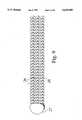
- FIG. 12shows a spiral-shaped lead and means to deploy it
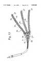
- FIG. 13shows a detail view of an electrode connection of a lead with several electrodes in parallel for subcutaneous implantation.
- FIG. 1shows a lead 18 having an electrode 20 electrically connected to a conductor coil 30 in two locations.
- the first connection 34is at the distal end of electrode 20, and the second connection 36 is at the proximal end. These connections can be welds, crimps, and the like, in any combination.
- the conductor coil 30is in turn electrically connected to connector 32 for coupling with a pulse generator such as the type described in U.S. Pat. No. 5,007,422 to Pless et al., which is assigned to the assignee of the present application.
- the lead body diameteris generally about 2.5 to 4.5 mm.
- FIG. 2shows a detail view of the distal connection of the lead 18 of FIG. 1.
- Electrode 20is shown to be constructed of many (six) electrode coils 24 helically wound around a flexible tubular supporting core 22, which may be either electrically conductive or insulative, and may be extruded or molded.
- This structurehas elastomeric material 28, which also may be conductive or insulative, partially encapsulating the electrode coils.
- the many electrode coilsincrease conductivity and redundancy.
- One method of achieving this structureis to completely encapsulate the wrapped electrode coils, then abrade away the surface to partially expose the coils using the method of Mar et al., U.S. Pat. No.
- a conductor 30extends through the lumen of core 22, making connection 34 at the distal end of electrode 20.
- Conductor 30is crimped to a sleeve 31 and to a pin 33.
- the distal ends of electrode coils 24are melted into balls 27, which are then welded to sleeve 31, forming an electrical connection to the conductor coil.
- This connectionis also described in U.S. patent application Ser. No. 08/126,291, filed 24 Sept. 1993 by Mar, for a "Defibrillation Electrode Connection" which is assigned to the assignee of the present application.
- connection 34is then covered by a protective cap 35, which may be electrically conductive or insulative.
- Protective cap 35seals the electrode connection from body fluids.
- Conductor coil 30forms an inner lumen 38 through which a stylet may be placed to stiffen the lead during implantation.
- Pin 33serves both as a support for coil 30 and sleeve 31 for crimping, and as a stop for the stylet.
- each electrode coil 24is made from a helically wound metal wire 26, which may be round or flat in cross section. This wire must be very strong, fatigue resistant, conductive, corrosion resistant, and biocompatible. Platinum iridium is one example of such a material. Electrode coil 24 is shown without an inner core; however, a thin wire or plastic filament could be located within coil 24 to provide either increased electrical conductivity, mechanical redundancy, or both. The filament could be metal or nylon, for example. In order for the lead to be sufficiently thin to be transvenously implantable, electrode coils 24 should be between about 0.2 and 0.4 mm, and wire 26 should be about 0.05 to 0.10 mm in diameter. Close winding of wire 26 into electrode coils 24 provides more exposed metal for charge transfer to tissue.
- space windingdecreases the lengths of wire in the coils, decreasing end to end electrode resistance. Additionally, space winding provides more surface for matrix material to mechanically stabilize coils and allows for a substantial volume of matrix material that can flex with the heart and body motion instead of pulling away from the coils. Therefore, a certain amount of space is preferred, typically one-half to one wire diameter space between wires.
- electrode coils 24can be close or space wound onto core 22. The same general principles apply. The distal end of each electrode coil 24 is melted into a ball 27, which provides more volume of material to form a strong and reliable crimp or weld. This melted ball structure works particularly well when made of a noble material such as a platinum iridium alloy.
- a hydrogen torchalso called a "water welder” is one suitable means for melting the coil to form the ball.
- This devicedissociates water into hydrogen and oxygen, then burns the hydrogen to form water again. This process burns cleanly, without incorporating byproducts into the melting coil, which is important for maintaining biocompatibility and material consistency for any subsequent welding.
- FIGS. 4A and 4Billustrate the process by which electrode coils 24 are embedded in elastomeric material 28, preferably silicone rubber.
- FIG. 4Ashows electrode coil 24 as molded over by elastomeric material 28.
- FIG. 4Bshows the structure of FIG. 4A, after a portion of elastomeric material 28 has been abraded away to partially expose electrode coil 24.
- the level of material removalis controllable. The more metal exposed, the greater the electrode surface area for defibrillation, but the less material for providing mechanical stability.
- FIG. 5shows a lead 18' with a pacing electrode 44, and lo electrode 20 which is used alternately for defibrillation and for sensing.
- Pacing electrode 44may be of any of the numerous constructions known in the art.
- a fixation mechanism 45is shown as tines, but may be any known in the art, including a screw used for both pacing and fixation.
- Pacing electrode 44is electrically connected to a pacing conductor coil 40, which is in turn connected to a pacing connector 43.
- Electrode 20is electrically connected at connection 34 to conductor coil 30, which is electrically connected to both defibrillation connector 32 and a sensing connector ring 39.
- FIG. 6shows a detail view of the distal end of the lead of FIG. 5.
- Electrode 20is shown to be constructed of a plurality of electrode coils 24 helically wound around flexible tubular supporting core 22. This structure has elastomeric material 28 partially encapsulating the electrode coils.
- Conductor 30extends through the lumen of core 22, making connection 34 at the distal end of electrode 20.
- Conductor 30is welded to the face of sleeve 29, as described in U.S. patent application Ser. No. 08/018,832, filed Feb. 18, 1993 by Bush et al., for an "Electrical Connection for Medical Electrical Stimulation Electrodes" which is assigned to the assignee of the present application and which is incorporated herein by reference.
- a pacing conductor coil 40extends through the lumen of tubular core 22 and is electrically insulated from conductor coil 30 by an insulator 42. Pacing conductor coil 40 is shown connected by a crimp connection to pacing electrode 44 and a crimp pin 41; this connection may alternatively be a weld.
- FIG. 7shows a detail view of electrical connection 34.
- the distal end of conductor coil 30has been welded to the face of sleeve 29.
- Electrode coils 24have had their distal ends melted into balls 27, then welded to the outside surface of sleeve 29.
- FIG. 8shows a cross sectional view of the proximal end of electrode 20.
- Two groups of electrode coils 24have their proximal ends melted into balls 27' to provide electrical redundancy.
- Molded electrode core tube 22has two pockets 25 in its proximal end into which balls 27' are placed prior to wrapping electrode coils 24 onto tube 22.
- a joining material 47for example silicone rubber.
- a mandrelis used to keep the lumen open during this process, so that the conductor can be passed through the joint and connected at the distal end of electrode 20.
- FIG. 9shows one group of three electrode coils 24 with proximal ends melted into ball 27'.
- This group of three electrode coilscan be wound onto a tube such as core tube 22 of FIG. 8 in several ways.
- the preferred methodis to insert a mandrel into a molded core tube, place the mandrel into a lathe-type coil winder, insert one group of three electrode coils 24 into each of two pockets of the tube, then use the coil winder to wind the electrode coils 24 around the tube.
- elastomeric materialmay be compression molded over the coils and core.
- An alternative methodis to embed electrode coils 24 into uncured elastomeric material that has been rolled into thin strips, then wrap the coil embedded strips of elastomeric material around a core tube, then cure the elastomeric material.
- a third alternativeis to apply uncured elastomeric material to a cured core, then wind electrode coils 24 about the core, embedding them into the elastomeric material.
- Yet a fourth alternativeis to manufacture the core and elastomeric material portion simultaneously by putting uncured rubber onto a mandrel to form both portions; electrode coils 24 are then embedded into the surface of the rubber, and the rubber is cured.
- FIG. 10shows a lead 18" with two defibrillation electrodes, 20' and 20", having opposite polarity, and a pacing electrode 44 as it is positioned within a patient's heart. Electrode 20' acts alternately as a defibrillation electrode and as a sensing electrode. The lead is shown as situated in the heart, with pacing electrode 44 and distal defibrillation electrode 20' in the right ventricle, and proximal defibrillation electrode 20" located in the superior vena cava.
- FIG. 11shows a lead with a J shaped defibrillation electrode 20 and with screw in tip 44', for use in the right ventricle or atrium, for example. Screw in tip 44' can be used for pacing and fixation, or for fixation alone.
- the preferred method of manufacturing a J shaped leadis to start with a tubular core which has been molded in a J shape. The J shaped tubular core is then straightened by inserting a mandrel into it. Then, electrode coils as described above are wound onto the straightened core. The tubular core and electrode coils are then reformed into the J shape by removing the straight mandrel, perhaps lo replacing it with a J shaped one. The tubular core with electrode coils is then molded over with elastomeric material, holding the electrode coils in their final J shape.
- FIG. 12shows a spiral electrode 20, and means for deploying it.
- a stylet 52is inserted through lead 18"' and is used to push electrode 20 through an introducer sheath 56.
- FIG. 13illustrates a lead with three electrodes 20, intended for implantation subcutaneously on the left lateral part of the chest. They are of the same polarity, and are connected to a common node on conductor 30. Electrode coils 24 are connected at distal ends by melted balls 27' and wound onto flexible cores 48. Flexible embedding material 50 partially covers electrode coils 24. The proximal ends of electrode coils 24 are all connected by melting them into ball 27". Ball 27" is crimped into metal joining piece 58. Also crimped to metal joining piece 58 is crimp sleeve 31 and conductor coil 30. A protective strain relief molding 60 encapsulates the entire connection.
- the electrode of the present inventioncan be made with a certain amount of resistance along its length, say, 3 to 15 ohms. This property of the electrode can be used to direct defibrillation energy to selected regions of the heart by careful choice of connection locations of electrode to conductor. For example, if the electrode 20 of FIG. 5 were placed with its distal end in the apex of the RV, current would be steered to the RV apex since that is where the conductor attaches to the electrode at connection 34. On the other hand, because of the electrode connections 34 and 36 on either end of electrode 20 of FIG. 1, the current distribution would be more even along the electrode length than in the electrode of FIG.
Landscapes
- Health & Medical Sciences (AREA)
- Heart & Thoracic Surgery (AREA)
- Cardiology (AREA)
- Nuclear Medicine, Radiotherapy & Molecular Imaging (AREA)
- Engineering & Computer Science (AREA)
- Biomedical Technology (AREA)
- Vascular Medicine (AREA)
- Radiology & Medical Imaging (AREA)
- Life Sciences & Earth Sciences (AREA)
- Animal Behavior & Ethology (AREA)
- General Health & Medical Sciences (AREA)
- Public Health (AREA)
- Veterinary Medicine (AREA)
- Electrotherapy Devices (AREA)
Abstract
Description
This invention relates to medical electrical stimulation electrodes in general and to implantable defibrillation electrodes in particular.
It is well known that cardiac arrhythmias such as ventricular fibrillation may be controlled with devices such as implantable defibrillators. Many different types of defibrillation electrodes have been suggested over the years, as can be seen from the following examples. In this discussion, no distinction will be made between cardioversion and defibrillation; both will be referred to as defibrillation.
U.S. Pat. No. 3,942,536 issued to Mirowski et al. discloses an intravascular bipolar catheter electrode system wherein each of two electrodes is composed of a plurality of spaced, low impedance rings. As implanted, the first electrode is located within the right ventricle (RV) and the second electrode is located in the superior vena cava (SVC).
In U.S. Pat. No. 4,161,952 issued to Kinney et al., a catheter electrode has a coil of wound spring wire, with filler material beneath and between individual turns of coil such that only the outside of the wound wire is exposed to the patient's body. It is designed to reside in or about the heart, as in the SVC or in the coronary sinus (CS).
U.S. Pat. No. 4,922,927 issued to Fine et al. teaches the use of tightly wound wire forming a tight coil on a support that is flared to provide a greater diameter along its midsection than at its ends, to form an RV electrode. A copper-zirconium alloy wrapped with tantalum and coated with iridium oxide is suggested for the tightly wound wire,
Other types of transvenously placed leads are disclosed in U.S. Pat. No. 4,998,975 issued to Cohen et al. One lead is placed through the heart wall, and into the pericardial space, and another is placed endocardially in a conventional manner. Both leads are shown with several embodiments, with the examples of general electrode construction being to expose a section of the conductor coil, or to use ring electrodes similar to those used in conventional bipolar pacemaker leads. Cohen et al. also describe two methods for steering more current to a selected region of the heart. The first method is to apply various voltages to the connectors of each of four electrodes. The second method uses the resistance of conductors, both between connector and electrode, and between two electrodes on the same lead, and the body tissue resistance between electrodes on different leads, to form a voltage divider, thus creating a different potential at each electrode.
Another lead system patent, U.S. Pat. No. 5,007,436 issued to Smits, describes electrodes of both J and straight configurations, for use in the RV, right atrium, great cardiac vein, or CS. The fabrication methods suggested use close wound conductive coils mounted exterior to an elongated insulative sheath, or the method of Kinney et al.
Spiral shaped electrodes for endocardial, epicardial, or extrapericardial implantation are described in Hell, Jr. et al., U.S. Pat. No. 5,016,808, Fogarty et al., U.S. Pat. No. 4,860,769, and Hauser et al., U.S. Pat. No. 5,052,407. The electrodes of these patents use various construction techniques, including electrodeposition or vapor deposition onto a plastic tube, helically wound wire (round or ribbon, unifilar or multifilar, single or double helix) or conductive rings on a flexible insulating portion, and conductive screen wrapped around a tubular body.
Other defibrillation leads are disclosed in Mehra et al., U.S. Pat. No. 5,144,960, and in Bardy et al., U.S. Pat. No. 5,174,288.
Endotak SQ Model 0048 (Cardiac Pacemakers Inc., St. Paul, Minn., USA), described in "A Subcutaneous Lead Array for Implantable Cardioverter Defibrillators" by Jordaens et al., published in PACE, Vol. 16, July 1993, Part I, is an electrode system consisting of three conductive elements that can be subcutaneously inserted. The conductive elements of this "array lead" are made of electrically common multifilar coil, joined in a silicone yoke, and separately introduced with a lead tunneler and peel-away sheaths.
As defibrillator technology improves and the demand for defibrillators increases, it becomes increasingly desirable to have leads available that are easily implanted. Any implantable defibrillation electrode must be capable of withstanding repeated flexing over a long period of time. In addition, the electrode must have sufficient surface area to discharge high amounts of energy for effective defibrillation, and must maintain its electrical integrity. The electrode must be of biocompatible materials, as well as of a shape that avoids tissue damage.
The present invention provides a lead with an improved electrode design for use with an implantable defibrillator system. In the preferred embodiment, a transvenous electrode is constructed from six tiny platinum iridium space wound coils, space wound onto a silicone rubber tube, molded over with silicone rubber, then partially exposed by abrading away the molded silicone by grit blasting with sodium bicarbonate. This electrode exhibits a high degree of flexibility and therefore can be positioned quickly and easily within the right ventricle, right atrium, or superior vena cava, for example. Its flexibility also permits insertion of a curved stylet to aid in placement. Because of its flexibility, it can adapt to the complex movement of the heart, and will not perforate the endocardium. Because of its coiled coil structure, the wire within the electrode flexes very little with electrode movement; therefore, the fatigue life is high. The use of small coiled coils may provide an electrode having a resistance greater than about one ohm. While prior art systems attempt to minimize electrode resistance, this feature is used to advantage with the present invention wherein current flow from the electrode may be controlled or modified by changing the location where the lead conductor is electrically connected to the electrode.
In an alternative embodiment, this electrode construction can be used on a lead designed for epicardial placement.
In a third embodiment, an electrode of this construction can be used on a lead designed for subcutaneous placement.
It is thus an object of the present invention to provide a lead with an improved electrode for an implantable defibrillator.
It is a further object of the invention to provide a lead requiring less time for implantation.
It is an additional object of the invention to provide a lead with an electrode that is more flexible and fatigue resistant than existing electrodes.
It is another object of the invention to provide a lead with an electrode that is easily manufactured.
It is another object of the invention to provide a method of electrode construction that could be used to enhance the performance of the lead configurations of the prior art.
The various features and advantages of the present invention may be more readily understood with reference to the following detailed description taken in conjunction with the accompanying drawings, wherein like reference numerals designate like structural elements, and in which:
FIG. 1 illustrates the defibrillation electrode of novel construction of the present invention;
FIG. 2 is a detail view, partially cut away and partially in section, of the distal connection of the lead of FIG. 1;
FIG. 3 is a detail view of the distal end of the electrode coil of FIG. 1;
FIGS. 4A and 4B illustrate the electrode of FIG. 1 during two manufacturing steps;
FIG. 5 illustrates an alternative embodiment of the invention which includes a pacing electrode, and uses the novel electrode for both defibrillation and sensing;
FIG. 6 shows a sectional view of the distal end of the lead of FIG. 5;
FIG. 7 shows a detail view of the electrical connection of the lead of FIG. 5;
FIG. 8 shows a cross sectional view of the proximal end of the electrode of FIG. 5;
FIG. 9 illustrates one step in the manufacture of the lead of FIG. 5;
FIG. 10 shows a lead implanted in the heart that includes two defibrillation electrodes and a pacing electrode;
FIG. 11 shows a J-shaped lead;
FIG. 12 shows a spiral-shaped lead and means to deploy it; and
FIG. 13 shows a detail view of an electrode connection of a lead with several electrodes in parallel for subcutaneous implantation.
FIG. 1 shows a lead 18 having anelectrode 20 electrically connected to aconductor coil 30 in two locations. Thefirst connection 34 is at the distal end ofelectrode 20, and thesecond connection 36 is at the proximal end. These connections can be welds, crimps, and the like, in any combination. Theconductor coil 30 is in turn electrically connected toconnector 32 for coupling with a pulse generator such as the type described in U.S. Pat. No. 5,007,422 to Pless et al., which is assigned to the assignee of the present application. The lead body diameter is generally about 2.5 to 4.5 mm.
FIG. 2 shows a detail view of the distal connection of thelead 18 of FIG. 1.Electrode 20 is shown to be constructed of many (six) electrode coils 24 helically wound around a flexibletubular supporting core 22, which may be either electrically conductive or insulative, and may be extruded or molded. This structure haselastomeric material 28, which also may be conductive or insulative, partially encapsulating the electrode coils. The many electrode coils increase conductivity and redundancy. One method of achieving this structure is to completely encapsulate the wrapped electrode coils, then abrade away the surface to partially expose the coils using the method of Mar et al., U.S. Pat. No. 5,226,260, which is assigned to the assignee of the present application and which is incorporated herein by reference. Aconductor 30 extends through the lumen ofcore 22, makingconnection 34 at the distal end ofelectrode 20.Conductor 30 is crimped to asleeve 31 and to apin 33. The distal ends of electrode coils 24 are melted intoballs 27, which are then welded tosleeve 31, forming an electrical connection to the conductor coil. This connection is also described in U.S. patent application Ser. No. 08/126,291, filed 24 Sept. 1993 by Mar, for a "Defibrillation Electrode Connection" which is assigned to the assignee of the present application. Theconnection 34 is then covered by aprotective cap 35, which may be electrically conductive or insulative.Protective cap 35 seals the electrode connection from body fluids.Conductor coil 30 forms aninner lumen 38 through which a stylet may be placed to stiffen the lead during implantation.Pin 33 serves both as a support forcoil 30 andsleeve 31 for crimping, and as a stop for the stylet.
FIG. 3 shows that eachelectrode coil 24 is made from a helicallywound metal wire 26, which may be round or flat in cross section. This wire must be very strong, fatigue resistant, conductive, corrosion resistant, and biocompatible. Platinum iridium is one example of such a material.Electrode coil 24 is shown without an inner core; however, a thin wire or plastic filament could be located withincoil 24 to provide either increased electrical conductivity, mechanical redundancy, or both. The filament could be metal or nylon, for example. In order for the lead to be sufficiently thin to be transvenously implantable, electrode coils 24 should be between about 0.2 and 0.4 mm, andwire 26 should be about 0.05 to 0.10 mm in diameter. Close winding ofwire 26 into electrode coils 24 provides more exposed metal for charge transfer to tissue. However, space winding decreases the lengths of wire in the coils, decreasing end to end electrode resistance. Additionally, space winding provides more surface for matrix material to mechanically stabilize coils and allows for a substantial volume of matrix material that can flex with the heart and body motion instead of pulling away from the coils. Therefore, a certain amount of space is preferred, typically one-half to one wire diameter space between wires. Similarly, electrode coils 24 can be close or space wound ontocore 22. The same general principles apply. The distal end of eachelectrode coil 24 is melted into aball 27, which provides more volume of material to form a strong and reliable crimp or weld. This melted ball structure works particularly well when made of a noble material such as a platinum iridium alloy. A hydrogen torch, also called a "water welder", is one suitable means for melting the coil to form the ball. This device dissociates water into hydrogen and oxygen, then burns the hydrogen to form water again. This process burns cleanly, without incorporating byproducts into the melting coil, which is important for maintaining biocompatibility and material consistency for any subsequent welding.
FIGS. 4A and 4B illustrate the process by which electrode coils 24 are embedded inelastomeric material 28, preferably silicone rubber. FIG. 4A showselectrode coil 24 as molded over byelastomeric material 28. FIG. 4B shows the structure of FIG. 4A, after a portion ofelastomeric material 28 has been abraded away to partially exposeelectrode coil 24. The level of material removal is controllable. The more metal exposed, the greater the electrode surface area for defibrillation, but the less material for providing mechanical stability.
FIG. 5 shows a lead 18' with a pacingelectrode 44, andlo electrode 20 which is used alternately for defibrillation and for sensing. Pacingelectrode 44 may be of any of the numerous constructions known in the art. Afixation mechanism 45 is shown as tines, but may be any known in the art, including a screw used for both pacing and fixation. Pacingelectrode 44 is electrically connected to apacing conductor coil 40, which is in turn connected to apacing connector 43.Electrode 20 is electrically connected atconnection 34 toconductor coil 30, which is electrically connected to bothdefibrillation connector 32 and asensing connector ring 39.
FIG. 6 shows a detail view of the distal end of the lead of FIG. 5.Electrode 20 is shown to be constructed of a plurality of electrode coils 24 helically wound around flexibletubular supporting core 22. This structure haselastomeric material 28 partially encapsulating the electrode coils.Conductor 30 extends through the lumen ofcore 22, makingconnection 34 at the distal end ofelectrode 20.Conductor 30 is welded to the face ofsleeve 29, as described in U.S. patent application Ser. No. 08/018,832, filed Feb. 18, 1993 by Bush et al., for an "Electrical Connection for Medical Electrical Stimulation Electrodes" which is assigned to the assignee of the present application and which is incorporated herein by reference. The distal ends of electrode coils 24 are melted intoballs 27, and are then welded tosleeve 29, formingelectrical connection 34 to the conductor coil. Apacing conductor coil 40 extends through the lumen oftubular core 22 and is electrically insulated fromconductor coil 30 by aninsulator 42.Pacing conductor coil 40 is shown connected by a crimp connection to pacingelectrode 44 and acrimp pin 41; this connection may alternatively be a weld.
FIG. 7 shows a detail view ofelectrical connection 34. The distal end ofconductor coil 30 has been welded to the face ofsleeve 29. Electrode coils 24 have had their distal ends melted intoballs 27, then welded to the outside surface ofsleeve 29.
FIG. 8 shows a cross sectional view of the proximal end ofelectrode 20. Two groups of electrode coils 24 have their proximal ends melted into balls 27' to provide electrical redundancy. Moldedelectrode core tube 22 has twopockets 25 in its proximal end into which balls 27' are placed prior to wrapping electrode coils 24 ontotube 22. Afterelastomeric material 28 is applied, anelectrical insulation 37 is joined toelectrode 20 using a joiningmaterial 47, for example silicone rubber. A mandrel is used to keep the lumen open during this process, so that the conductor can be passed through the joint and connected at the distal end ofelectrode 20.
FIG. 9 shows one group of threeelectrode coils 24 with proximal ends melted into ball 27'. This group of three electrode coils can be wound onto a tube such ascore tube 22 of FIG. 8 in several ways. The preferred method is to insert a mandrel into a molded core tube, place the mandrel into a lathe-type coil winder, insert one group of threeelectrode coils 24 into each of two pockets of the tube, then use the coil winder to wind the electrode coils 24 around the tube. After the electrode coils 24 are wound onto the core tube, elastomeric material may be compression molded over the coils and core. An alternative method is to embedelectrode coils 24 into uncured elastomeric material that has been rolled into thin strips, then wrap the coil embedded strips of elastomeric material around a core tube, then cure the elastomeric material. A third alternative is to apply uncured elastomeric material to a cured core, then wind electrode coils 24 about the core, embedding them into the elastomeric material. Yet a fourth alternative is to manufacture the core and elastomeric material portion simultaneously by putting uncured rubber onto a mandrel to form both portions; electrode coils 24 are then embedded into the surface of the rubber, and the rubber is cured.
FIG. 10 shows a lead 18" with two defibrillation electrodes, 20' and 20", having opposite polarity, and apacing electrode 44 as it is positioned within a patient's heart. Electrode 20' acts alternately as a defibrillation electrode and as a sensing electrode. The lead is shown as situated in the heart, with pacingelectrode 44 and distal defibrillation electrode 20' in the right ventricle, andproximal defibrillation electrode 20" located in the superior vena cava.
FIG. 11 shows a lead with a J shapeddefibrillation electrode 20 and with screw in tip 44', for use in the right ventricle or atrium, for example. Screw in tip 44' can be used for pacing and fixation, or for fixation alone. The preferred method of manufacturing a J shaped lead is to start with a tubular core which has been molded in a J shape. The J shaped tubular core is then straightened by inserting a mandrel into it. Then, electrode coils as described above are wound onto the straightened core. The tubular core and electrode coils are then reformed into the J shape by removing the straight mandrel, perhaps lo replacing it with a J shaped one. The tubular core with electrode coils is then molded over with elastomeric material, holding the electrode coils in their final J shape.
FIG. 12 shows aspiral electrode 20, and means for deploying it. Astylet 52 is inserted throughlead 18"' and is used to pushelectrode 20 through anintroducer sheath 56.
FIG. 13 illustrates a lead with threeelectrodes 20, intended for implantation subcutaneously on the left lateral part of the chest. They are of the same polarity, and are connected to a common node onconductor 30. Electrode coils 24 are connected at distal ends by melted balls 27' and wound ontoflexible cores 48. Flexible embeddingmaterial 50 partially covers electrode coils 24. The proximal ends of electrode coils 24 are all connected by melting them intoball 27".Ball 27" is crimped intometal joining piece 58. Also crimped tometal joining piece 58 iscrimp sleeve 31 andconductor coil 30. A protectivestrain relief molding 60 encapsulates the entire connection.
Because the electrode coil wire is longer and thinner than the electrode elements of the prior art, the electrode of the present invention can be made with a certain amount of resistance along its length, say, 3 to 15 ohms. This property of the electrode can be used to direct defibrillation energy to selected regions of the heart by careful choice of connection locations of electrode to conductor. For example, if theelectrode 20 of FIG. 5 were placed with its distal end in the apex of the RV, current would be steered to the RV apex since that is where the conductor attaches to the electrode atconnection 34. On the other hand, because of theelectrode connections electrode 20 of FIG. 1, the current distribution would be more even along the electrode length than in the electrode of FIG. 5, since the potential is the same at either end, assuming a verylow resistance conductor 30. In this case, the end to end electrode resistance is also reduced, with the highest resistance being in the middle of the electrode. The connection could also be made in the middle of the electrode, instead of or in addition to the ends. With the electrode connected to the conductor in only the middle of the electrode and not the ends, current density would be more even since end effects would be reduced. Several connections between the conductor and the electrode may be made along the length of one electrode. This is desirable for reducing overall resistance, particularly when the electrode is long, as in the lead of FIG. 12.
The above has been offered for illustrative purposes only and is not intended to limit the scope of the invention of this application, which is as defined in the claims below.
Claims (23)
1. A body implantable lead including at least one electrode having a proximal end and a distal end, comprising:
a flexible tubular supporting core having a lumen therethrough;
at least one electrode coil helically wound about said core, said at least one electrode coil having a proximal end corresponding to said electrode proximal end and a distal end corresponding to said electrode distal end and comprising at least one helically wound metal wire and being connected at one of said ends to a conductor; and
a matrix of elastomeric material partially encapsulating said electrode coil and holding said electrode coil in said helically wound position around said core.
2. The lead of claim 1 in which said conductor is attached to a connector for connection of said lead with an implantable defibrillator.
3. The lead of claim 1 in which said core is insulative.
4. The lead of claim 1 in which said core is conductive.
5. The lead of claim 1 in which said wire is round in cross section.
6. The lead of claim 1 in which said wire is flat and substantially rectangular in cross section.
7. The lead of claim 1 in which said wire is made of a platinum iridium alloy.
8. The lead of claim 1 in which said matrix is insulative.
9. The lead of claim 1 in which said matrix is conductive.
10. The lead of claim 1 in which said wire is between about 0.05 and 0.10 mm in diameter.
11. The lead of claim 1 in which said at least one coil is between about 0.2 and 0.4 mm in outer diameter.
12. The lead of claim 1 in which said conductor is a coil that extends through the lumen of said tubular core.
13. The lead of claim 12 in which said conductor coil is electrically connected to said electrode coil at said distal end of said electrode coil.
14. The lead of claim 12 in which said conductor coil is electrically connected to said electrode coil at both ends of said electrode coil.
15. The lead of claim 12 in which said conductor coil is electrically connected to said electrode coil at a location between said proximal end and said distal end of said electrode coil.
16. The lead of claim 12 in which at least a portion of said conductor coil forms an inner lumen capable of accommodating a stylet.
17. The lead of claim 12 in which at least a portion of said conductor coil forms an inner lumen through which extends an insulated conductor.
18. The lead of claim 1 in which said wire is space wound.
19. The lead of claim 1 in which said electrode coils are space wound about said tubular core.
20. The lead of claim 1 in which said electrode is J shaped.
21. A body implantable lead including at least one defibrillation electrode having a proximal end and a distal end, comprising:
a flexible core;
at least one electrode coil comprising at least one helically wound wire;
each said at least one electrode coil being helically wound about said core, said at least one electrode coil having a proximal end corresponding to said electrode proximal end and a distal end corresponding to said electrode distal end and being connected at one of said ends to a conductor; and
said electrode coil being partially embedded in flexible material and thereby held in fixed position around said core.
22. The lead of claim 21 and further including a plurality of said electrodes electrically connected at a common node.
23. A body implantable lead including at least one defibrillation electrode comprising:
a flexible core:
at least one electrode coil helically wound about said core, said at least one electrode coil comprising at least one helically wound metal wire and being connected at one end to a conductor for connecting said electrode to an implantable pulse generator; and
wherein said electrode has a resistivity along its length greater than one ohm whereby current flowing from said electrode differs depending on the location of the connection between said conductor and said electrode.
Priority Applications (2)
| Application Number | Priority Date | Filing Date | Title |
|---|---|---|---|
| US08/126,619US5439485A (en) | 1993-09-24 | 1993-09-24 | Flexible defibrillation electrode of improved construction |
| US08/388,766US5542173A (en) | 1993-09-24 | 1995-02-15 | Method of making flexible defibrillation electrode |
Applications Claiming Priority (1)
| Application Number | Priority Date | Filing Date | Title |
|---|---|---|---|
| US08/126,619US5439485A (en) | 1993-09-24 | 1993-09-24 | Flexible defibrillation electrode of improved construction |
Related Child Applications (1)
| Application Number | Title | Priority Date | Filing Date |
|---|---|---|---|
| US08/388,766DivisionUS5542173A (en) | 1993-09-24 | 1995-02-15 | Method of making flexible defibrillation electrode |
Publications (1)
| Publication Number | Publication Date |
|---|---|
| US5439485Atrue US5439485A (en) | 1995-08-08 |
Family
ID=22425827
Family Applications (2)
| Application Number | Title | Priority Date | Filing Date |
|---|---|---|---|
| US08/126,619Expired - Fee RelatedUS5439485A (en) | 1993-09-24 | 1993-09-24 | Flexible defibrillation electrode of improved construction |
| US08/388,766Expired - Fee RelatedUS5542173A (en) | 1993-09-24 | 1995-02-15 | Method of making flexible defibrillation electrode |
Family Applications After (1)
| Application Number | Title | Priority Date | Filing Date |
|---|---|---|---|
| US08/388,766Expired - Fee RelatedUS5542173A (en) | 1993-09-24 | 1995-02-15 | Method of making flexible defibrillation electrode |
Country Status (1)
| Country | Link |
|---|---|
| US (2) | US5439485A (en) |
Cited By (100)
| Publication number | Priority date | Publication date | Assignee | Title |
|---|---|---|---|---|
| US5534022A (en)* | 1994-11-22 | 1996-07-09 | Ventritex, Inc. | Lead having an integrated defibrillation/sensing electrode |
| US5683447A (en)* | 1995-12-19 | 1997-11-04 | Ventritex, Inc. | Lead with septal defibrillation and pacing electrodes |
| US5709644A (en)* | 1996-06-14 | 1998-01-20 | Pacesetter, Inc. | Implantable suture sleeve modified to reduce tissue ingrowth |
| US5713945A (en)* | 1996-06-13 | 1998-02-03 | Pacesetter, Inc. | Implantable lead modified to reduce tissue ingrowth |
| US5728149A (en)* | 1995-12-20 | 1998-03-17 | Medtronic, Inc. | Integral spiral band electrode for transvenous defibrillation leads |
| WO1998011939A1 (en)* | 1996-09-20 | 1998-03-26 | Uab Research Foundation | Line electrode oriented relative to fiber direction |
| US5846469A (en)* | 1996-05-30 | 1998-12-08 | Pacesetter, Inc. | Method for manufacturing a defibrillation electrode |
| US5916213A (en)* | 1997-02-04 | 1999-06-29 | Medtronic, Inc. | Systems and methods for tissue mapping and ablation |
| US5931862A (en)* | 1997-12-22 | 1999-08-03 | Pacesetter, Inc. | Medical lead and method of making and using with sodium sulfosuccinic ester |
| US5995871A (en)* | 1997-10-29 | 1999-11-30 | Uab Research Foundation | System and method for cardioversion using scan stimulation |
| EP0927561A3 (en)* | 1997-12-29 | 2000-03-08 | BIOTRONIK Mess- und Therapiegeräte GmbH & Co Ingenieurbüro Berlin | Defibrillation electrode device |
| DE19925854A1 (en)* | 1999-06-02 | 2000-12-07 | Biotronik Mess & Therapieg | Electrode arrangement |
| DE19925853A1 (en)* | 1999-06-02 | 2000-12-07 | Biotronik Mess & Therapieg | Cardioversion arrangement |
| US6159165A (en) | 1997-12-05 | 2000-12-12 | Micrus Corporation | Three dimensional spherical micro-coils manufactured from radiopaque nickel-titanium microstrand |
| US6168570B1 (en) | 1997-12-05 | 2001-01-02 | Micrus Corporation | Micro-strand cable with enhanced radiopacity |
| US6181973B1 (en) | 1999-04-02 | 2001-01-30 | Claudio Ceron | Anchoring structure for implantable electrodes |
| US6241691B1 (en) | 1997-12-05 | 2001-06-05 | Micrus Corporation | Coated superelastic stent |
| WO2002032500A1 (en) | 2000-10-17 | 2002-04-25 | Medtronic, Inc. | Radiopaque marking of lead electrode zone in a continuous conductor construction |
| US6456889B2 (en) | 2000-05-15 | 2002-09-24 | Pacesetter, Inc. | Lead with polymeric tubular liner for guidewire and stylet insertion |
| US6456890B2 (en) | 2000-05-15 | 2002-09-24 | Pacesetter, Inc. | Lead with polymeric tubular liner for guidewire and stylet insertion |
| US6475214B1 (en) | 2000-05-01 | 2002-11-05 | Biosense Webster, Inc. | Catheter with enhanced ablation electrode |
| US20030092303A1 (en)* | 2001-11-09 | 2003-05-15 | Osypka Thomas P. | Multifilar conductor for cardiac leads |
| US6615695B1 (en) | 2000-06-27 | 2003-09-09 | Medtronic, Inc. | Alternative fabrication method for spiral electrodes |
| US6671561B1 (en) | 2000-05-01 | 2003-12-30 | Biosense Webster, Inc. | Catheter with electrode having hydrogel layer |
| US6684109B1 (en) | 2000-09-13 | 2004-01-27 | Oscor Inc. | Endocardial lead |
| US20040054390A1 (en)* | 2002-09-13 | 2004-03-18 | Zarembo Paul E. | Method and device for supporting or strengthening a portion of a lead |
| US6721597B1 (en)* | 2000-09-18 | 2004-04-13 | Cameron Health, Inc. | Subcutaneous only implantable cardioverter defibrillator and optional pacer |
| US20040186529A1 (en)* | 2000-09-18 | 2004-09-23 | Cameron Health, Inc. | Subcutaneous electrode for transthoracic conduction with highly maneuverable insertion tool |
| US20040210293A1 (en)* | 2000-09-18 | 2004-10-21 | Cameron Health, Inc. | Subcutaneous electrode for transthoracic conduction with insertion tool |
| US20040210294A1 (en)* | 2000-09-18 | 2004-10-21 | Cameron Health, Inc. | Subcutaneous electrode for transthoracic conduction with low profile installation appendage |
| US20040215308A1 (en)* | 2000-09-18 | 2004-10-28 | Cameron Health, Inc. | Subcutaneous electrode with improved contact shape for transthoracic conduction |
| US20040236379A1 (en)* | 2001-11-21 | 2004-11-25 | Cameron Health, Inc. | Apparatus and method of arrhythmia detection in a subcutaneous implantable cardioverter/defibrillator |
| US20040254613A1 (en)* | 2001-11-21 | 2004-12-16 | Cameron Health, Inc. | Method for discriminating between ventricular and supraventricular arrhythmias |
| US20040260353A1 (en)* | 2000-09-18 | 2004-12-23 | Cameron Health, Inc. | Radian curve shaped implantable cardioverter-defibrillator canister |
| US20050065559A1 (en)* | 2000-09-18 | 2005-03-24 | Cameron Health, Inc. | Monophasic waveform for anti-tachycardia pacing for a subcutaneous implantable cardioverter-defibrillator |
| US20050137625A1 (en)* | 2000-09-18 | 2005-06-23 | Cameron Health, Inc. | Power supply for a subcutaneous implantable cardioverter-defibrillator |
| US20050240113A1 (en)* | 2001-11-05 | 2005-10-27 | Cameron Health, Inc. | Low power A/D converter |
| US20060001070A1 (en)* | 2004-05-03 | 2006-01-05 | Samsung Electronics Co., Ltd. | Capacitor of a memory device and fabrication method thereof |
| US20060004416A1 (en)* | 2000-09-18 | 2006-01-05 | Cameron Health, Inc. | Canister designs for implantable cardioverter-defibrillators |
| US20060047323A1 (en)* | 2004-08-25 | 2006-03-02 | Foley Stephen T | Gastrointestinal stimulation lead |
| US20060089681A1 (en)* | 2004-10-21 | 2006-04-27 | Cameron Health, Inc. | Implantable medical device |
| US20060116725A1 (en)* | 2004-11-29 | 2006-06-01 | Cameron Health, Inc. | Method and apparatus for beat alignment and comparison |
| US20060116595A1 (en)* | 2004-11-29 | 2006-06-01 | Cameron Health, Inc. | Method for defining signal templates in implantable cardiac devices |
| US20060122676A1 (en)* | 2004-12-06 | 2006-06-08 | Cameron Health, Inc. | Apparatus and method for subcutaneous electrode insertion |
| US20060241698A1 (en)* | 2005-04-26 | 2006-10-26 | Cameron Health, Inc. | Methods and implantable devices for inducing fibrillation by alternating constant current |
| US7239925B2 (en) | 2000-09-18 | 2007-07-03 | Cameron Health, Inc. | Subcutaneous electrode for transthoracic conduction with improved installation characteristics |
| US7248921B2 (en) | 2003-06-02 | 2007-07-24 | Cameron Health, Inc. | Method and devices for performing cardiac waveform appraisal |
| US20070185556A1 (en)* | 2002-04-11 | 2007-08-09 | Williams Terrell M | Medical electrical lead body designs incorporating energy dissipating shunt |
| US20070208383A1 (en)* | 2002-04-11 | 2007-09-06 | Williams Terrell M | Medical electrical lead body designs incorporating energy dissipating shunt |
| US20080015644A1 (en)* | 2006-07-14 | 2008-01-17 | Cameron Health, Inc. | End of life battery testing in an implantable medical device |
| US7392085B2 (en) | 2001-11-21 | 2008-06-24 | Cameron Health, Inc. | Multiple electrode vectors for implantable cardiac treatment devices |
| US7623909B2 (en) | 2006-05-26 | 2009-11-24 | Cameron Health, Inc. | Implantable medical devices and programmers adapted for sensing vector selection |
| US7623913B2 (en) | 2006-08-01 | 2009-11-24 | Cameron Health, Inc. | Implantable medical devices using heuristic filtering in cardiac event detection |
| US7623916B2 (en) | 2006-12-20 | 2009-11-24 | Cameron Health, Inc. | Implantable cardiac stimulus devices and methods with input recharge circuitry |
| US7783340B2 (en) | 2007-01-16 | 2010-08-24 | Cameron Health, Inc. | Systems and methods for sensing vector selection in an implantable medical device using a polynomial approach |
| US7813797B2 (en) | 2000-09-18 | 2010-10-12 | Cameron Health, Inc. | Cardioverter-defibrillator having a focused shocking area and orientation thereof |
| EP2226096A3 (en)* | 2009-03-04 | 2010-12-15 | European Custom Manufacturing B.V. | Electrical connector for conveying an electrical signal from a device to an organ of a human or animal body |
| US20110009934A1 (en)* | 2009-07-13 | 2011-01-13 | Pacesetter, Inc. | Implantable medical lead having passive lock mechanical body terminations |
| US7877139B2 (en) | 2006-09-22 | 2011-01-25 | Cameron Health, Inc. | Method and device for implantable cardiac stimulus device lead impedance measurement |
| EP1759732B1 (en)* | 2000-11-22 | 2011-07-20 | Medtronic, Inc. | Apparatus for detecting and treating ventricular arrhythmia |
| US8014851B2 (en) | 2006-09-26 | 2011-09-06 | Cameron Health, Inc. | Signal analysis in implantable cardiac treatment devices |
| US8116867B2 (en) | 2005-08-04 | 2012-02-14 | Cameron Health, Inc. | Methods and devices for tachyarrhythmia sensing and high-pass filter bypass |
| US20120089213A1 (en)* | 2010-10-07 | 2012-04-12 | W. C. Heraeus Gmbh | Medical lead with filler layer |
| US8160697B2 (en) | 2005-01-25 | 2012-04-17 | Cameron Health, Inc. | Method for adapting charge initiation for an implantable cardioverter-defibrillator |
| US8200341B2 (en) | 2007-02-07 | 2012-06-12 | Cameron Health, Inc. | Sensing vector selection in a cardiac stimulus device with postural assessment |
| US8229563B2 (en) | 2005-01-25 | 2012-07-24 | Cameron Health, Inc. | Devices for adapting charge initiation for an implantable cardioverter-defibrillator |
| US8447398B2 (en) | 2000-09-18 | 2013-05-21 | Cameron Health, Inc. | Subcutaneous implantable cardioverter-defibrillator placement methods |
| US8718793B2 (en) | 2006-08-01 | 2014-05-06 | Cameron Health, Inc. | Electrode insertion tools, lead assemblies, kits and methods for placement of cardiac device electrodes |
| US8788023B2 (en) | 2006-05-26 | 2014-07-22 | Cameron Health, Inc. | Systems and methods for sensing vector selection in an implantable medical device |
| US20140309512A1 (en)* | 2013-04-11 | 2014-10-16 | Biosense Webster (Israel), Ltd. | High density electrode structure |
| US9144683B2 (en) | 2000-09-18 | 2015-09-29 | Cameron Health, Inc. | Post-shock treatment in a subcutaneous device |
| US9149645B2 (en) | 2013-03-11 | 2015-10-06 | Cameron Health, Inc. | Methods and devices implementing dual criteria for arrhythmia detection |
| US9579065B2 (en) | 2013-03-12 | 2017-02-28 | Cameron Health Inc. | Cardiac signal vector selection with monophasic and biphasic shape consideration |
| US10575743B2 (en) | 2013-04-11 | 2020-03-03 | Biosense Webster (Israel) Ltd. | High electrode density basket catheter |
| US10850104B2 (en) | 2015-07-10 | 2020-12-01 | Axonics Modulation Technologies, Inc. | Implantable nerve stimulator having internal electronics without ASIC and methods of use |
| CN112135658A (en)* | 2018-05-09 | 2020-12-25 | 美敦力公司 | Bonding strip for securing electrode coil to lead body |
| US10971950B2 (en) | 2013-07-29 | 2021-04-06 | The Alfred E. Mann Foundation For Scientific Research | Microprocessor controlled class E driver |
| US11083903B2 (en) | 2016-01-29 | 2021-08-10 | Axonics, Inc. | Methods and systems for frequency adjustment to optimize charging of implantable neurostimulator |
| US11103703B2 (en) | 2016-08-11 | 2021-08-31 | Advanced Bionics Ag | Cochlear implants including electrode arrays and methods of making the same |
| US11110283B2 (en) | 2018-02-22 | 2021-09-07 | Axonics, Inc. | Neurostimulation leads for trial nerve stimulation and methods of use |
| US11116985B2 (en) | 2014-08-15 | 2021-09-14 | Axonics, Inc. | Clinician programmer for use with an implantable neurostimulation lead |
| US11123569B2 (en) | 2015-01-09 | 2021-09-21 | Axonics, Inc. | Patient remote and associated methods of use with a nerve stimulation system |
| US11213675B2 (en) | 2014-08-15 | 2022-01-04 | Axonics, Inc. | Implantable lead affixation structure for nerve stimulation to alleviate bladder dysfunction and other indication |
| US11260236B2 (en) | 2016-02-12 | 2022-03-01 | Axonics, Inc. | External pulse generator device and affixation device for trial nerve stimulation and methods of use |
| US11338144B2 (en) | 2013-03-15 | 2022-05-24 | Alfred E. Mann Foundation For Scientific Research | Current sensing multiple output current stimulators |
| US11389659B2 (en) | 2014-08-15 | 2022-07-19 | Axonics, Inc. | External pulse generator device and associated methods for trial nerve stimulation |
| US11439829B2 (en) | 2019-05-24 | 2022-09-13 | Axonics, Inc. | Clinician programmer methods and systems for maintaining target operating temperatures |
| US11452865B2 (en) | 2019-10-10 | 2022-09-27 | Advanced Bionics Ag | Apparatus and methods for making cochlear implant electrode arrays |
| US11471668B2 (en) | 2019-12-21 | 2022-10-18 | Advanced Bionics Ag | Apparatus and methods for making cochlear implant electrode arrays |
| US11478648B2 (en) | 2015-01-09 | 2022-10-25 | Axonics, Inc. | Antenna and methods of use for an implantable nerve stimulator |
| US11484723B2 (en) | 2015-01-09 | 2022-11-01 | Axonics, Inc. | Attachment devices and associated methods of use with a nerve stimulation charging device |
| US11497916B2 (en) | 2014-08-15 | 2022-11-15 | Axonics, Inc. | Electromyographic lead positioning and stimulation titration in a nerve stimulation system for treatment of overactive bladder |
| US11642537B2 (en) | 2019-03-11 | 2023-05-09 | Axonics, Inc. | Charging device with off-center coil |
| US11730411B2 (en) | 2014-08-15 | 2023-08-22 | Axonics, Inc. | Methods for determining neurostimulation electrode configurations based on neural localization |
| US11833348B2 (en) | 2021-07-09 | 2023-12-05 | The Alfred E. Mann Foundation For Scientific Research | Electrode leads having multi-application helical nerve cuffs and associated systems and methods |
| US11848090B2 (en) | 2019-05-24 | 2023-12-19 | Axonics, Inc. | Trainer for a neurostimulator programmer and associated methods of use with a neurostimulation system |
| US12194290B2 (en) | 2020-09-02 | 2025-01-14 | The Alfred E. Mann Foundation For Scientific Research | Electrode leads having multi-application nerve cuffs and associated systems and methods |
| US12296172B2 (en) | 2022-02-01 | 2025-05-13 | The Alfred E. Mann Foundation For Scientific Research | Electrode leads having nerve contact elements with coil contacts and associated systems and methods |
| US12350489B2 (en) | 2021-03-30 | 2025-07-08 | The Alfred E. Mann Foundation For Scientific Research | Electrode leads having nerve cuffs and associated systems and methods |
| US12420103B1 (en) | 2020-08-20 | 2025-09-23 | Axonics, Inc. | Neurostimulation leads with reduced current leakage |
Families Citing this family (15)
| Publication number | Priority date | Publication date | Assignee | Title |
|---|---|---|---|---|
| US5658327A (en)* | 1995-12-19 | 1997-08-19 | Ventritex, Inc. | Intracardiac lead having a compliant fixation device |
| US5897586A (en)* | 1997-08-15 | 1999-04-27 | Regents Of The University Of Minnesota | Implantable defibrillator lead |
| US6216045B1 (en) | 1999-04-26 | 2001-04-10 | Advanced Neuromodulation Systems, Inc. | Implantable lead and method of manufacture |
| US6324414B1 (en)* | 1999-05-18 | 2001-11-27 | Depuy Orthopaedics, Inc. | Tunneling lead terminal having a disposal sheath |
| US6501991B1 (en)* | 2000-06-21 | 2002-12-31 | Medtronic, Inc. | Electrically-isolated multiple conductor lead body |
| US20080161887A1 (en)* | 2006-12-28 | 2008-07-03 | Cvrx, Inc. | Noble metal electrodes with nanostructures |
| US9084883B2 (en) | 2009-03-12 | 2015-07-21 | Cardiac Pacemakers, Inc. | Thin profile conductor assembly for medical device leads |
| US9254380B2 (en)* | 2009-10-19 | 2016-02-09 | Cardiac Pacemakers, Inc. | MRI compatible tachycardia lead |
| US9750944B2 (en) | 2009-12-30 | 2017-09-05 | Cardiac Pacemakers, Inc. | MRI-conditionally safe medical device lead |
| WO2011081713A1 (en) | 2009-12-31 | 2011-07-07 | Cardiac Pacemakers, Inc. | Mri conditionally safe lead with multi-layer conductor |
| US8391994B2 (en) | 2009-12-31 | 2013-03-05 | Cardiac Pacemakers, Inc. | MRI conditionally safe lead with low-profile multi-layer conductor for longitudinal expansion |
| US8954168B2 (en) | 2012-06-01 | 2015-02-10 | Cardiac Pacemakers, Inc. | Implantable device lead including a distal electrode assembly with a coiled component |
| JP6069499B2 (en) | 2012-08-31 | 2017-02-01 | カーディアック ペースメイカーズ, インコーポレイテッド | Lead wire with low peak MRI heating |
| US8983623B2 (en) | 2012-10-18 | 2015-03-17 | Cardiac Pacemakers, Inc. | Inductive element for providing MRI compatibility in an implantable medical device lead |
| WO2015130753A1 (en) | 2014-02-26 | 2015-09-03 | Cardiac Pacemakers, Inc | Construction of an mri-safe tachycardia lead |
Citations (17)
| Publication number | Priority date | Publication date | Assignee | Title |
|---|---|---|---|---|
| US3572344A (en)* | 1968-12-31 | 1971-03-23 | Medtronic Inc | Electrode apparatus with lead construction |
| US3788329A (en)* | 1972-04-17 | 1974-01-29 | Medtronic Inc | Body implantable lead |
| US3942536A (en)* | 1971-03-15 | 1976-03-09 | Mieczyslaw Mirowski | Cardioverting device having single intravascular catheter electrode system and method for its use |
| US4161952A (en)* | 1977-11-01 | 1979-07-24 | Mieczyslaw Mirowski | Wound wire catheter cardioverting electrode |
| US4860769A (en)* | 1987-11-12 | 1989-08-29 | Thomas J. Fogarty | Implantable defibrillation electrode |
| US4922927A (en)* | 1987-12-30 | 1990-05-08 | Intermedics, Inc. | Transvenous defibrillating and pacing lead |
| US4998975A (en)* | 1989-10-30 | 1991-03-12 | Siemens-Pacesetter, Inc. | Travenously placed defibrillation leads |
| US5007436A (en)* | 1985-06-20 | 1991-04-16 | Medtronic, Inc. | Cardioversion and defibrillation lead system |
| US5007422A (en)* | 1989-06-06 | 1991-04-16 | Ventritex, Inc. | Method for combiner cardiac pacing and defibrillation |
| US5016808A (en)* | 1989-09-14 | 1991-05-21 | Cardiac Pacemakers, Inc. | Implantable tapered spiral endocardial lead for use in internal defibrillation |
| US5052407A (en)* | 1988-04-14 | 1991-10-01 | Mieczyslaw Mirowski | Cardiac defibrillation/cardioversion spiral patch electrode |
| US5115818A (en)* | 1990-02-14 | 1992-05-26 | Medtronic, Inc. | Implantable electrode |
| WO1992013481A1 (en)* | 1991-02-04 | 1992-08-20 | Edison Biotechnology Center | Double helix fes electrode |
| US5144960A (en)* | 1991-03-20 | 1992-09-08 | Medtronic, Inc. | Transvenous defibrillation lead and method of use |
| US5174288A (en)* | 1990-11-30 | 1992-12-29 | Medtronic, Inc. | Method and apparatus for cardiac defibrillation |
| US5226260A (en)* | 1992-01-09 | 1993-07-13 | Ventritex, Inc. | Method for manufacturing implantable cardiac defibrillation leads utilizing a material removal process |
| US5265623A (en)* | 1992-07-16 | 1993-11-30 | Angeion Corporation | Optimized field defibrillation catheter |
Family Cites Families (5)
| Publication number | Priority date | Publication date | Assignee | Title |
|---|---|---|---|---|
| US4698890A (en)* | 1985-10-31 | 1987-10-13 | The Gates Rubber Company | Method for making a formable and curve shape retentive hose |
| IT1192812B (en)* | 1986-07-04 | 1988-05-12 | Comind Spa Azienda Ages | AUTOMATIC FORMING DEVICE OF GENERICALLY CYLINDRICAL ELASTOMERIC MATERIALS OBTAINED BY INJECTION IN MOLDS WITH COMBINED MATRICES AND MOLD PROVIDED WITH THE SAID DEVICE |
| US4904431A (en)* | 1988-08-12 | 1990-02-27 | Baxter International, Inc. | Process for manufacturing catheters |
| US5171262A (en)* | 1989-06-15 | 1992-12-15 | Cordis Corporation | Non-woven endoprosthesis |
| JPH0447402U (en)* | 1990-08-24 | 1992-04-22 |
- 1993
- 1993-09-24USUS08/126,619patent/US5439485A/ennot_activeExpired - Fee Related
- 1995
- 1995-02-15USUS08/388,766patent/US5542173A/ennot_activeExpired - Fee Related
Patent Citations (18)
| Publication number | Priority date | Publication date | Assignee | Title |
|---|---|---|---|---|
| US3572344A (en)* | 1968-12-31 | 1971-03-23 | Medtronic Inc | Electrode apparatus with lead construction |
| US3942536A (en)* | 1971-03-15 | 1976-03-09 | Mieczyslaw Mirowski | Cardioverting device having single intravascular catheter electrode system and method for its use |
| US3942536B1 (en)* | 1971-03-15 | 1987-03-24 | ||
| US3788329A (en)* | 1972-04-17 | 1974-01-29 | Medtronic Inc | Body implantable lead |
| US4161952A (en)* | 1977-11-01 | 1979-07-24 | Mieczyslaw Mirowski | Wound wire catheter cardioverting electrode |
| US5007436A (en)* | 1985-06-20 | 1991-04-16 | Medtronic, Inc. | Cardioversion and defibrillation lead system |
| US4860769A (en)* | 1987-11-12 | 1989-08-29 | Thomas J. Fogarty | Implantable defibrillation electrode |
| US4922927A (en)* | 1987-12-30 | 1990-05-08 | Intermedics, Inc. | Transvenous defibrillating and pacing lead |
| US5052407A (en)* | 1988-04-14 | 1991-10-01 | Mieczyslaw Mirowski | Cardiac defibrillation/cardioversion spiral patch electrode |
| US5007422A (en)* | 1989-06-06 | 1991-04-16 | Ventritex, Inc. | Method for combiner cardiac pacing and defibrillation |
| US5016808A (en)* | 1989-09-14 | 1991-05-21 | Cardiac Pacemakers, Inc. | Implantable tapered spiral endocardial lead for use in internal defibrillation |
| US4998975A (en)* | 1989-10-30 | 1991-03-12 | Siemens-Pacesetter, Inc. | Travenously placed defibrillation leads |
| US5115818A (en)* | 1990-02-14 | 1992-05-26 | Medtronic, Inc. | Implantable electrode |
| US5174288A (en)* | 1990-11-30 | 1992-12-29 | Medtronic, Inc. | Method and apparatus for cardiac defibrillation |
| WO1992013481A1 (en)* | 1991-02-04 | 1992-08-20 | Edison Biotechnology Center | Double helix fes electrode |
| US5144960A (en)* | 1991-03-20 | 1992-09-08 | Medtronic, Inc. | Transvenous defibrillation lead and method of use |
| US5226260A (en)* | 1992-01-09 | 1993-07-13 | Ventritex, Inc. | Method for manufacturing implantable cardiac defibrillation leads utilizing a material removal process |
| US5265623A (en)* | 1992-07-16 | 1993-11-30 | Angeion Corporation | Optimized field defibrillation catheter |
Non-Patent Citations (2)
| Title |
|---|
| "A Subcutaneous Lead Array for Implantable Cardioverter Defibrillators", Jordaens, et al., PACE, vol. 16, Part I (Jul. 1993). |
| A Subcutaneous Lead Array for Implantable Cardioverter Defibrillators , Jordaens, et al., PACE, vol. 16, Part I (Jul. 1993).* |
Cited By (188)
| Publication number | Priority date | Publication date | Assignee | Title |
|---|---|---|---|---|
| US5534022A (en)* | 1994-11-22 | 1996-07-09 | Ventritex, Inc. | Lead having an integrated defibrillation/sensing electrode |
| US5683447A (en)* | 1995-12-19 | 1997-11-04 | Ventritex, Inc. | Lead with septal defibrillation and pacing electrodes |
| US5728149A (en)* | 1995-12-20 | 1998-03-17 | Medtronic, Inc. | Integral spiral band electrode for transvenous defibrillation leads |
| US5846469A (en)* | 1996-05-30 | 1998-12-08 | Pacesetter, Inc. | Method for manufacturing a defibrillation electrode |
| US5713945A (en)* | 1996-06-13 | 1998-02-03 | Pacesetter, Inc. | Implantable lead modified to reduce tissue ingrowth |
| US5709644A (en)* | 1996-06-14 | 1998-01-20 | Pacesetter, Inc. | Implantable suture sleeve modified to reduce tissue ingrowth |
| WO1998011939A1 (en)* | 1996-09-20 | 1998-03-26 | Uab Research Foundation | Line electrode oriented relative to fiber direction |
| US5824028A (en)* | 1996-09-20 | 1998-10-20 | The Uab Research Foundation | Line electrode oriented relative to fiber direction |
| US6068629A (en)* | 1997-02-04 | 2000-05-30 | Medtronic, Inc. | System and methods for tissue mapping and ablation |
| US5916213A (en)* | 1997-02-04 | 1999-06-29 | Medtronic, Inc. | Systems and methods for tissue mapping and ablation |
| US5995871A (en)* | 1997-10-29 | 1999-11-30 | Uab Research Foundation | System and method for cardioversion using scan stimulation |
| US6475169B2 (en) | 1997-12-05 | 2002-11-05 | Micrus Corporation | Micro-strand cable with enhanced radiopacity |
| US6616617B1 (en) | 1997-12-05 | 2003-09-09 | Micrus Corporation | Vasoocclusive device for treatment of aneurysms |
| US6159165A (en) | 1997-12-05 | 2000-12-12 | Micrus Corporation | Three dimensional spherical micro-coils manufactured from radiopaque nickel-titanium microstrand |
| US6168570B1 (en) | 1997-12-05 | 2001-01-02 | Micrus Corporation | Micro-strand cable with enhanced radiopacity |
| US6241691B1 (en) | 1997-12-05 | 2001-06-05 | Micrus Corporation | Coated superelastic stent |
| US7326225B2 (en) | 1997-12-05 | 2008-02-05 | Micrus Endovascular Corporation | Vasoocclusive device for treatment of aneurysms |
| US6497671B2 (en) | 1997-12-05 | 2002-12-24 | Micrus Corporation | Coated superelastic stent |
| US5931862A (en)* | 1997-12-22 | 1999-08-03 | Pacesetter, Inc. | Medical lead and method of making and using with sodium sulfosuccinic ester |
| EP0927561A3 (en)* | 1997-12-29 | 2000-03-08 | BIOTRONIK Mess- und Therapiegeräte GmbH & Co Ingenieurbüro Berlin | Defibrillation electrode device |
| US6181973B1 (en) | 1999-04-02 | 2001-01-30 | Claudio Ceron | Anchoring structure for implantable electrodes |
| DE19925853A1 (en)* | 1999-06-02 | 2000-12-07 | Biotronik Mess & Therapieg | Cardioversion arrangement |
| US6516231B1 (en) | 1999-06-02 | 2003-02-04 | Daniel Flammang | Endocardial electrode lead with multiple branches |
| US6889093B1 (en) | 1999-06-02 | 2005-05-03 | Biotronik Mes-und Therpiegeräte GmbH & Co. Ingenieurbüro Berlin | Electrode lead with multiple branches |
| DE19925854A1 (en)* | 1999-06-02 | 2000-12-07 | Biotronik Mess & Therapieg | Electrode arrangement |
| US6475214B1 (en) | 2000-05-01 | 2002-11-05 | Biosense Webster, Inc. | Catheter with enhanced ablation electrode |
| US6671561B1 (en) | 2000-05-01 | 2003-12-30 | Biosense Webster, Inc. | Catheter with electrode having hydrogel layer |
| US6456890B2 (en) | 2000-05-15 | 2002-09-24 | Pacesetter, Inc. | Lead with polymeric tubular liner for guidewire and stylet insertion |
| US6456889B2 (en) | 2000-05-15 | 2002-09-24 | Pacesetter, Inc. | Lead with polymeric tubular liner for guidewire and stylet insertion |
| US6615695B1 (en) | 2000-06-27 | 2003-09-09 | Medtronic, Inc. | Alternative fabrication method for spiral electrodes |
| US6684109B1 (en) | 2000-09-13 | 2004-01-27 | Oscor Inc. | Endocardial lead |
| US20040260353A1 (en)* | 2000-09-18 | 2004-12-23 | Cameron Health, Inc. | Radian curve shaped implantable cardioverter-defibrillator canister |
| US20070021791A1 (en)* | 2000-09-18 | 2007-01-25 | Cameron Health, Inc. | Transthoracic impedance measurement in a subcutaneous device |
| US7657311B2 (en) | 2000-09-18 | 2010-02-02 | Cameron Health, Inc. | Subcutaneous only implantable cardioverter-defibrillator and optional pacer |
| US7720534B2 (en) | 2000-09-18 | 2010-05-18 | Cameron Health, Inc. | Transthoracic impedance measurement in a subcutaneous device |
| US6721597B1 (en)* | 2000-09-18 | 2004-04-13 | Cameron Health, Inc. | Subcutaneous only implantable cardioverter defibrillator and optional pacer |
| US20040172071A1 (en)* | 2000-09-18 | 2004-09-02 | Cameron Health, Inc. | Subcutaneous only implantable cardioverter-defibrillator and optional pacer |
| US20040186529A1 (en)* | 2000-09-18 | 2004-09-23 | Cameron Health, Inc. | Subcutaneous electrode for transthoracic conduction with highly maneuverable insertion tool |
| US20040210293A1 (en)* | 2000-09-18 | 2004-10-21 | Cameron Health, Inc. | Subcutaneous electrode for transthoracic conduction with insertion tool |
| US20040210294A1 (en)* | 2000-09-18 | 2004-10-21 | Cameron Health, Inc. | Subcutaneous electrode for transthoracic conduction with low profile installation appendage |
| US20040215308A1 (en)* | 2000-09-18 | 2004-10-28 | Cameron Health, Inc. | Subcutaneous electrode with improved contact shape for transthoracic conduction |
| US7813797B2 (en) | 2000-09-18 | 2010-10-12 | Cameron Health, Inc. | Cardioverter-defibrillator having a focused shocking area and orientation thereof |
| US7536222B2 (en) | 2000-09-18 | 2009-05-19 | Cameron Health, Inc. | Nonvascular implantable defibrillator and method |
| US7627375B2 (en) | 2000-09-18 | 2009-12-01 | Cameron Health, Inc. | Implantable cardiac stimulus methods |
| US20050065559A1 (en)* | 2000-09-18 | 2005-03-24 | Cameron Health, Inc. | Monophasic waveform for anti-tachycardia pacing for a subcutaneous implantable cardioverter-defibrillator |
| US7428437B2 (en) | 2000-09-18 | 2008-09-23 | Cameron Health, Inc. | Canister designs for implantable cardioverter-defibrillators |
| US20050137625A1 (en)* | 2000-09-18 | 2005-06-23 | Cameron Health, Inc. | Power supply for a subcutaneous implantable cardioverter-defibrillator |
| US7302300B2 (en) | 2000-09-18 | 2007-11-27 | Cameron Health, Inc. | Subcutaneous electrode for transthoracic conduction with highly maneuverable insertion tool |
| US7299092B2 (en) | 2000-09-18 | 2007-11-20 | Cameron Health, Inc. | Subcutaneous electrode for transthoracic conduction with low profile installation appendage |
| US7299097B2 (en) | 2000-09-18 | 2007-11-20 | Cameron Health, Inc. | Subcutaneous electrode for transthoracic conduction with insertion tool |
| US20060004416A1 (en)* | 2000-09-18 | 2006-01-05 | Cameron Health, Inc. | Canister designs for implantable cardioverter-defibrillators |
| US7274962B2 (en) | 2000-09-18 | 2007-09-25 | Cameron Health, Inc. | Subcutaneous electrode with improved contact shape for transthoracic conduction |
| US8160699B2 (en) | 2000-09-18 | 2012-04-17 | Cameron Health, Inc. | Cardioverter-defibrillator having a focused shocking area and orientation thereof |
| US9144683B2 (en) | 2000-09-18 | 2015-09-29 | Cameron Health, Inc. | Post-shock treatment in a subcutaneous device |
| US7239925B2 (en) | 2000-09-18 | 2007-07-03 | Cameron Health, Inc. | Subcutaneous electrode for transthoracic conduction with improved installation characteristics |
| US7181274B2 (en) | 2000-09-18 | 2007-02-20 | Cameron Health, Inc. | Methods for inducing fibrillation utilizing subcutaneous electrodes |
| US7076294B2 (en) | 2000-09-18 | 2006-07-11 | Cameron Health, Inc. | Method of implanting ICD and subcutaneous lead |
| US7120496B2 (en) | 2000-09-18 | 2006-10-10 | Cameron Health, Inc. | Radian curve shaped implantable cardioverter-defibrillator canister |
| US20060235479A1 (en)* | 2000-09-18 | 2006-10-19 | Cameron Health, Inc. | Monophasic waveform for anti-bradycardia pacing for a subcutaneous implantable cardioverter-defibrillator |
| US8447398B2 (en) | 2000-09-18 | 2013-05-21 | Cameron Health, Inc. | Subcutaneous implantable cardioverter-defibrillator placement methods |
| US20030045920A1 (en)* | 2000-10-17 | 2003-03-06 | Medtronic, Inc. | Radiopaque marking of lead electrode zone in a continuous conductor construction |
| US7925358B2 (en) | 2000-10-17 | 2011-04-12 | Medtronic, Inc. | Radiopaque marking of lead electrode zone in a continuous conductor construction |
| US20110160573A1 (en)* | 2000-10-17 | 2011-06-30 | Medtronic Inc. | Radiopaque Marking of Lead Electrode Zone in a Continuous Conductor Construction |
| US6501992B1 (en) | 2000-10-17 | 2002-12-31 | Medtronic, Inc. | Radiopaque marking of lead electrode zone in a continuous conductor construction |
| US7277762B2 (en)* | 2000-10-17 | 2007-10-02 | Belden Elisabeth L | Radiopague marking of lead electrode zone in a continuous conductor construction |
| WO2002032500A1 (en) | 2000-10-17 | 2002-04-25 | Medtronic, Inc. | Radiopaque marking of lead electrode zone in a continuous conductor construction |
| US20070293924A1 (en)* | 2000-10-17 | 2007-12-20 | Belden Elisabeth L | Radiopaque marking of lead electrode zone in a continuous conductor construction |
| EP1759732B1 (en)* | 2000-11-22 | 2011-07-20 | Medtronic, Inc. | Apparatus for detecting and treating ventricular arrhythmia |
| US9022962B2 (en) | 2000-11-22 | 2015-05-05 | Boston Scientific Scimed, Inc. | Apparatus for detecting and treating ventricular arrhythmia |
| US7623920B2 (en) | 2001-11-05 | 2009-11-24 | Cameron Health, Inc. | Low power A/D converter |
| US20050240113A1 (en)* | 2001-11-05 | 2005-10-27 | Cameron Health, Inc. | Low power A/D converter |
| US20030092303A1 (en)* | 2001-11-09 | 2003-05-15 | Osypka Thomas P. | Multifilar conductor for cardiac leads |
| US6978185B2 (en) | 2001-11-09 | 2005-12-20 | Oscor Inc. | Multifilar conductor for cardiac leads |
| US7330757B2 (en) | 2001-11-21 | 2008-02-12 | Cameron Health, Inc. | Method for discriminating between ventricular and supraventricular arrhythmias |
| US7444182B2 (en) | 2001-11-21 | 2008-10-28 | Cameron Health, Inc. | Method for discriminating between ventricular and supraventricular arrhythmias |
| US9138589B2 (en) | 2001-11-21 | 2015-09-22 | Cameron Health, Inc. | Apparatus and method for identifying atrial arrhythmia by far-field sensing |
| US20040236379A1 (en)* | 2001-11-21 | 2004-11-25 | Cameron Health, Inc. | Apparatus and method of arrhythmia detection in a subcutaneous implantable cardioverter/defibrillator |
| US7379772B2 (en) | 2001-11-21 | 2008-05-27 | Cameron Health, Inc. | Apparatus and method of arrhythmia detection in a subcutaneous implantable cardioverter/defibrillator |
| US7392085B2 (en) | 2001-11-21 | 2008-06-24 | Cameron Health, Inc. | Multiple electrode vectors for implantable cardiac treatment devices |
| US20040254613A1 (en)* | 2001-11-21 | 2004-12-16 | Cameron Health, Inc. | Method for discriminating between ventricular and supraventricular arrhythmias |
| US7627367B2 (en) | 2001-11-21 | 2009-12-01 | Cameron Health, Inc. | Multiple electrode vectors for implantable cardiac treatment devices |
| US9522283B2 (en) | 2001-11-21 | 2016-12-20 | Cameron Health Inc. | Apparatus and method for identifying atrial arrhythmia by far-field sensing |
| US9993653B2 (en) | 2001-11-21 | 2018-06-12 | Cameron Health, Inc. | Apparatus and method for identifying atrial arrhythmia by far-field sensing |
| US7904178B2 (en) | 2002-04-11 | 2011-03-08 | Medtronic, Inc. | Medical electrical lead body designs incorporating energy dissipating shunt |
| US20070185556A1 (en)* | 2002-04-11 | 2007-08-09 | Williams Terrell M | Medical electrical lead body designs incorporating energy dissipating shunt |
| US20070208383A1 (en)* | 2002-04-11 | 2007-09-06 | Williams Terrell M | Medical electrical lead body designs incorporating energy dissipating shunt |
| US8396568B2 (en)* | 2002-04-11 | 2013-03-12 | Medtronic, Inc. | Medical electrical lead body designs incorporating energy dissipating shunt |
| US7486994B2 (en) | 2002-09-13 | 2009-02-03 | Cardiac Pacemakers, Inc. | Method and device for supporting or strengthening a portion of a lead |
| US20040054390A1 (en)* | 2002-09-13 | 2004-03-18 | Zarembo Paul E. | Method and device for supporting or strengthening a portion of a lead |
| WO2004024228A1 (en)* | 2002-09-13 | 2004-03-25 | Cardiac Pacemakers, Inc. | Method and device for supporting or strengtheing a lead |
| US9968796B2 (en) | 2003-05-29 | 2018-05-15 | Cameron Health, Inc. | Method for discriminating between ventricular and supraventricular arrhythmias |
| US9555259B2 (en) | 2003-05-29 | 2017-01-31 | Cameron Health Inc. | Method for discriminating between ventricular and supraventricular arrhythmias |
| US8942802B2 (en) | 2003-05-29 | 2015-01-27 | Cameron Health, Inc. | Method for discriminating between ventricular and supraventricular arrhythmias |
| US11020602B2 (en) | 2003-05-29 | 2021-06-01 | Cameron Health, Inc. | Method for discriminating between ventricular and supraventricular arrhythmias |
| US9155485B2 (en) | 2003-05-29 | 2015-10-13 | Cameron Health, Inc. | Method for discriminating between ventricular and supraventricular arrhythmias |
| US10183171B2 (en) | 2003-05-29 | 2019-01-22 | Cameron Health, Inc. | Method for discriminating between ventricular and supraventricular arrhythmias |
| US8626285B2 (en) | 2003-06-02 | 2014-01-07 | Cameron Health, Inc. | Method and devices for performing cardiac waveform appraisal |
| US7248921B2 (en) | 2003-06-02 | 2007-07-24 | Cameron Health, Inc. | Method and devices for performing cardiac waveform appraisal |
| US20060001070A1 (en)* | 2004-05-03 | 2006-01-05 | Samsung Electronics Co., Ltd. | Capacitor of a memory device and fabrication method thereof |
| WO2006026114A3 (en)* | 2004-08-25 | 2006-11-23 | Transneuronix Inc | Gastrointestinal stimulation lead |
| US20060047323A1 (en)* | 2004-08-25 | 2006-03-02 | Foley Stephen T | Gastrointestinal stimulation lead |
| US7519433B2 (en)* | 2004-08-25 | 2009-04-14 | Medtronic Transneuronix, Inc. | Gastrointestinal stimulation lead |
| US20060089681A1 (en)* | 2004-10-21 | 2006-04-27 | Cameron Health, Inc. | Implantable medical device |
| US20060116595A1 (en)* | 2004-11-29 | 2006-06-01 | Cameron Health, Inc. | Method for defining signal templates in implantable cardiac devices |
| US7991459B2 (en) | 2004-11-29 | 2011-08-02 | Cameron Health, Inc. | Method for defining signal templates in implantable cardiac devices |
| US7376458B2 (en) | 2004-11-29 | 2008-05-20 | Cameron Health, Inc. | Method for defining signal templates in implantable cardiac devices |
| US7477935B2 (en) | 2004-11-29 | 2009-01-13 | Cameron Health, Inc. | Method and apparatus for beat alignment and comparison |
| US20060116725A1 (en)* | 2004-11-29 | 2006-06-01 | Cameron Health, Inc. | Method and apparatus for beat alignment and comparison |
| US20060122676A1 (en)* | 2004-12-06 | 2006-06-08 | Cameron Health, Inc. | Apparatus and method for subcutaneous electrode insertion |
| US7655014B2 (en) | 2004-12-06 | 2010-02-02 | Cameron Health, Inc. | Apparatus and method for subcutaneous electrode insertion |
| US10052487B2 (en) | 2005-01-25 | 2018-08-21 | Cameron Health, Inc. | Methods and devices for adapting charge initiation for an implantable defibrillator |
| US11083897B2 (en) | 2005-01-25 | 2021-08-10 | Cameron Health, Inc. | Methods and devices for adapting charge initiation for an implantable defibrillator |
| US8160697B2 (en) | 2005-01-25 | 2012-04-17 | Cameron Health, Inc. | Method for adapting charge initiation for an implantable cardioverter-defibrillator |
| US8229563B2 (en) | 2005-01-25 | 2012-07-24 | Cameron Health, Inc. | Devices for adapting charge initiation for an implantable cardioverter-defibrillator |
| US20060241698A1 (en)* | 2005-04-26 | 2006-10-26 | Cameron Health, Inc. | Methods and implantable devices for inducing fibrillation by alternating constant current |
| US7555338B2 (en) | 2005-04-26 | 2009-06-30 | Cameron Health, Inc. | Methods and implantable devices for inducing fibrillation by alternating constant current |
| US8116867B2 (en) | 2005-08-04 | 2012-02-14 | Cameron Health, Inc. | Methods and devices for tachyarrhythmia sensing and high-pass filter bypass |
| US7623909B2 (en) | 2006-05-26 | 2009-11-24 | Cameron Health, Inc. | Implantable medical devices and programmers adapted for sensing vector selection |
| US9357969B2 (en) | 2006-05-26 | 2016-06-07 | Cameron Health, Inc. | Sensing vector selection in a cardiac stimulus device with postural assessment |
| US9364677B2 (en) | 2006-05-26 | 2016-06-14 | Cameron Health, Inc. | Systems and methods for sensing vector selection in an implantable medical device |
| US9744366B2 (en) | 2006-05-26 | 2017-08-29 | Cameron Health, Inc. | Sensing vector selection in a cardiac stimulus device with postural assessment |
| US8965530B2 (en) | 2006-05-26 | 2015-02-24 | Cameron Health, Inc. | Implantable cardiac devices and methods using an x/y counter |
| US8788023B2 (en) | 2006-05-26 | 2014-07-22 | Cameron Health, Inc. | Systems and methods for sensing vector selection in an implantable medical device |
| US10575740B2 (en) | 2006-05-26 | 2020-03-03 | Cameron Health Inc. | Systems and methods for sensing vector selection in an implantable medical device |
| US20080015644A1 (en)* | 2006-07-14 | 2008-01-17 | Cameron Health, Inc. | End of life battery testing in an implantable medical device |
| US8718793B2 (en) | 2006-08-01 | 2014-05-06 | Cameron Health, Inc. | Electrode insertion tools, lead assemblies, kits and methods for placement of cardiac device electrodes |
| US7623913B2 (en) | 2006-08-01 | 2009-11-24 | Cameron Health, Inc. | Implantable medical devices using heuristic filtering in cardiac event detection |
| US9216284B2 (en) | 2006-08-01 | 2015-12-22 | Cameron Health, Inc. | Electrode insertion tools, lead assemblies, kits and methods for placement of cardiac device electrodes |
| US7877139B2 (en) | 2006-09-22 | 2011-01-25 | Cameron Health, Inc. | Method and device for implantable cardiac stimulus device lead impedance measurement |
| US8014851B2 (en) | 2006-09-26 | 2011-09-06 | Cameron Health, Inc. | Signal analysis in implantable cardiac treatment devices |
| US7623916B2 (en) | 2006-12-20 | 2009-11-24 | Cameron Health, Inc. | Implantable cardiac stimulus devices and methods with input recharge circuitry |
| US7783340B2 (en) | 2007-01-16 | 2010-08-24 | Cameron Health, Inc. | Systems and methods for sensing vector selection in an implantable medical device using a polynomial approach |
| US10016609B2 (en) | 2007-02-07 | 2018-07-10 | Cameron Health, Inc. | Sensing vector selection in a cardiac stimulus device with postural assessment |
| US8781602B2 (en) | 2007-02-07 | 2014-07-15 | Cameron Health, Inc. | Sensing vector selection in a cardiac stimulus device with postural assessment |
| US8200341B2 (en) | 2007-02-07 | 2012-06-12 | Cameron Health, Inc. | Sensing vector selection in a cardiac stimulus device with postural assessment |
| EP2226096A3 (en)* | 2009-03-04 | 2010-12-15 | European Custom Manufacturing B.V. | Electrical connector for conveying an electrical signal from a device to an organ of a human or animal body |
| US8554341B2 (en)* | 2009-07-13 | 2013-10-08 | Pacesetter, Inc. | Implantable medical lead having passive lock mechanical body terminations |
| US20110009934A1 (en)* | 2009-07-13 | 2011-01-13 | Pacesetter, Inc. | Implantable medical lead having passive lock mechanical body terminations |
| US8321033B2 (en)* | 2009-07-13 | 2012-11-27 | Pacesetter, Inc. | Implantable medical lead having passive lock mechanical body terminations |
| US20130030509A1 (en)* | 2009-07-13 | 2013-01-31 | Pacesetter, Inc. | Implantable medical lead having passive lock mechanical body terminations |
| US20130025122A1 (en)* | 2009-07-13 | 2013-01-31 | Pacesetter, Inc. | Method of assembling an implantable medical lead having passive lock mechanical body terminations |
| US8588939B2 (en)* | 2009-07-13 | 2013-11-19 | Pacesetter, Inc. | Method of assembling an implantable medical lead having passive lock mechanical body terminations |
| US20120089213A1 (en)* | 2010-10-07 | 2012-04-12 | W. C. Heraeus Gmbh | Medical lead with filler layer |
| US9014816B2 (en)* | 2010-10-07 | 2015-04-21 | W. C. Heraeus Gmbh | Medical lead with filler layer |
| US9844678B2 (en) | 2013-03-11 | 2017-12-19 | Cameron Health, Inc. | Methods and devices implementing dual criteria for arrhythmia detection |
| US9421390B2 (en) | 2013-03-11 | 2016-08-23 | Cameron Health Inc. | Methods and devices implementing dual criteria for arrhythmia detection |
| US9149645B2 (en) | 2013-03-11 | 2015-10-06 | Cameron Health, Inc. | Methods and devices implementing dual criteria for arrhythmia detection |
| US9579065B2 (en) | 2013-03-12 | 2017-02-28 | Cameron Health Inc. | Cardiac signal vector selection with monophasic and biphasic shape consideration |
| US11338144B2 (en) | 2013-03-15 | 2022-05-24 | Alfred E. Mann Foundation For Scientific Research | Current sensing multiple output current stimulators |
| US10575743B2 (en) | 2013-04-11 | 2020-03-03 | Biosense Webster (Israel) Ltd. | High electrode density basket catheter |
| US10582869B2 (en) | 2013-04-11 | 2020-03-10 | Biosense Webster (Israel) Ltd. | Connection of electrodes to wires coiled on a core |
| US10602947B2 (en)* | 2013-04-11 | 2020-03-31 | Biosense Webster (Israel), Ltd. | High density electrode structure |
| US20140309512A1 (en)* | 2013-04-11 | 2014-10-16 | Biosense Webster (Israel), Ltd. | High density electrode structure |
| US11722007B2 (en) | 2013-07-29 | 2023-08-08 | The Alfred E. Mann Foundation For Scientific Rsrch | Microprocessor controlled class E driver |
| US10971950B2 (en) | 2013-07-29 | 2021-04-06 | The Alfred E. Mann Foundation For Scientific Research | Microprocessor controlled class E driver |
| US11213675B2 (en) | 2014-08-15 | 2022-01-04 | Axonics, Inc. | Implantable lead affixation structure for nerve stimulation to alleviate bladder dysfunction and other indication |
| US11730411B2 (en) | 2014-08-15 | 2023-08-22 | Axonics, Inc. | Methods for determining neurostimulation electrode configurations based on neural localization |
| US11116985B2 (en) | 2014-08-15 | 2021-09-14 | Axonics, Inc. | Clinician programmer for use with an implantable neurostimulation lead |
| US11497916B2 (en) | 2014-08-15 | 2022-11-15 | Axonics, Inc. | Electromyographic lead positioning and stimulation titration in a nerve stimulation system for treatment of overactive bladder |
| US11389659B2 (en) | 2014-08-15 | 2022-07-19 | Axonics, Inc. | External pulse generator device and associated methods for trial nerve stimulation |
| US11123569B2 (en) | 2015-01-09 | 2021-09-21 | Axonics, Inc. | Patient remote and associated methods of use with a nerve stimulation system |
| US11478648B2 (en) | 2015-01-09 | 2022-10-25 | Axonics, Inc. | Antenna and methods of use for an implantable nerve stimulator |
| US11484723B2 (en) | 2015-01-09 | 2022-11-01 | Axonics, Inc. | Attachment devices and associated methods of use with a nerve stimulation charging device |
| US11766568B2 (en) | 2015-07-10 | 2023-09-26 | Axonics, Inc. | Implantable nerve stimulator having internal electronics without ASIC and methods of use |
| US10850104B2 (en) | 2015-07-10 | 2020-12-01 | Axonics Modulation Technologies, Inc. | Implantable nerve stimulator having internal electronics without ASIC and methods of use |
| US11083903B2 (en) | 2016-01-29 | 2021-08-10 | Axonics, Inc. | Methods and systems for frequency adjustment to optimize charging of implantable neurostimulator |
| US12083349B2 (en) | 2016-01-29 | 2024-09-10 | Axonics, Inc. | Methods and systems for frequency adjustment to optimize charging of implantable neurostimulator |
| US11602638B2 (en) | 2016-01-29 | 2023-03-14 | Axonics, Inc. | Methods and systems for frequency adjustment to optimize charging of implantable neurostimulator |
| US12226643B2 (en) | 2016-02-12 | 2025-02-18 | Axonics, Inc. | External pulse generator device and affixation device for trial nerve stimulation and methods of use |
| US11260236B2 (en) | 2016-02-12 | 2022-03-01 | Axonics, Inc. | External pulse generator device and affixation device for trial nerve stimulation and methods of use |
| US11103703B2 (en) | 2016-08-11 | 2021-08-31 | Advanced Bionics Ag | Cochlear implants including electrode arrays and methods of making the same |
| US11986654B2 (en) | 2016-08-11 | 2024-05-21 | Advanced Bionics Ag | Methods of making cochlear implant electrode arrays |
| US12042662B2 (en) | 2018-02-22 | 2024-07-23 | Axonics, Inc. | Neurostimulation leads for trial nerve stimulation and methods of use |
| US11511122B2 (en) | 2018-02-22 | 2022-11-29 | Axonics, Inc. | Neurostimulation leads for trial nerve stimulation and methods of use |
| US11110283B2 (en) | 2018-02-22 | 2021-09-07 | Axonics, Inc. | Neurostimulation leads for trial nerve stimulation and methods of use |
| CN112135658A (en)* | 2018-05-09 | 2020-12-25 | 美敦力公司 | Bonding strip for securing electrode coil to lead body |
| US11291833B2 (en)* | 2018-05-09 | 2022-04-05 | Medtronic, Inc. | Bonding strip for fixing an electrode coil to a lead body |
| CN112135658B (en)* | 2018-05-09 | 2024-08-09 | 美敦力公司 | Bonding strips for securing the electrode coil to the lead body |
| US11642537B2 (en) | 2019-03-11 | 2023-05-09 | Axonics, Inc. | Charging device with off-center coil |
| US11848090B2 (en) | 2019-05-24 | 2023-12-19 | Axonics, Inc. | Trainer for a neurostimulator programmer and associated methods of use with a neurostimulation system |
| US11439829B2 (en) | 2019-05-24 | 2022-09-13 | Axonics, Inc. | Clinician programmer methods and systems for maintaining target operating temperatures |
| US11452865B2 (en) | 2019-10-10 | 2022-09-27 | Advanced Bionics Ag | Apparatus and methods for making cochlear implant electrode arrays |
| US11471668B2 (en) | 2019-12-21 | 2022-10-18 | Advanced Bionics Ag | Apparatus and methods for making cochlear implant electrode arrays |
| US12420103B1 (en) | 2020-08-20 | 2025-09-23 | Axonics, Inc. | Neurostimulation leads with reduced current leakage |
| US12194290B2 (en) | 2020-09-02 | 2025-01-14 | The Alfred E. Mann Foundation For Scientific Research | Electrode leads having multi-application nerve cuffs and associated systems and methods |
| US12350489B2 (en) | 2021-03-30 | 2025-07-08 | The Alfred E. Mann Foundation For Scientific Research | Electrode leads having nerve cuffs and associated systems and methods |
| US11833348B2 (en) | 2021-07-09 | 2023-12-05 | The Alfred E. Mann Foundation For Scientific Research | Electrode leads having multi-application helical nerve cuffs and associated systems and methods |
| US12296172B2 (en) | 2022-02-01 | 2025-05-13 | The Alfred E. Mann Foundation For Scientific Research | Electrode leads having nerve contact elements with coil contacts and associated systems and methods |
Also Published As
| Publication number | Publication date |
|---|---|
| US5542173A (en) | 1996-08-06 |
Similar Documents
| Publication | Publication Date | Title |
|---|---|---|
| US5439485A (en) | Flexible defibrillation electrode of improved construction | |
| US5488768A (en) | Method of forming a defibrillation electrode connection | |
| US5534022A (en) | Lead having an integrated defibrillation/sensing electrode | |
| US4161952A (en) | Wound wire catheter cardioverting electrode | |
| US5728149A (en) | Integral spiral band electrode for transvenous defibrillation leads | |
| US7158837B2 (en) | Low profile cardiac leads | |
| US5483022A (en) | Implantable conductor coil formed from cabled composite wire | |
| US5324328A (en) | Conductor for a defibrillator patch lead | |
| US8831748B2 (en) | Medical electrical electrodes with conductive polymer | |
| US9901731B2 (en) | Medical electrical lead having improved inductance | |
| US7277762B2 (en) | Radiopague marking of lead electrode zone in a continuous conductor construction | |
| US5649974A (en) | Low profile defibrillation catheter | |
| EP2376179B1 (en) | Implantable lead | |
| US7280875B1 (en) | High strength, low resistivity electrode | |
| US20110220408A1 (en) | Electrode and connector attachments for a cylindrical glass fiber wire lead | |
| EP1904156A2 (en) | Multiple electrode implantable lead and related method | |
| EP2044972B1 (en) | Implantable medical device lead conductor | |
| US20060200216A1 (en) | Fabrication of electrical medical leads employing multi-filar wire conductors | |
| US20040215300A1 (en) | Electrical medical leads employing conductive aerogel | |
| JP2008521581A (en) | High impedance active fixed electrode for electrical medical leads | |
| EP1441803A2 (en) | Multifilar conductor for endocardial leads | |
| AU1258492A (en) | Transvenous defibrillation lead and method of use | |
| WO1996006655A1 (en) | Low profile defibrillation catheter | |
| US20050004642A1 (en) | Implantable medical lead including overlay | |
| AU2013206194B2 (en) | Implantable lead |
Legal Events
| Date | Code | Title | Description |
|---|---|---|---|
| AS | Assignment | Owner name:VENTRITEX, INC., CALIFORNIA Free format text:ASSIGNMENT OF ASSIGNORS INTEREST;ASSIGNORS:MAR, CRAIG E.;PLESS, BENJAMIN D.;BUSH, M. ELIZABETH;REEL/FRAME:006727/0832;SIGNING DATES FROM 19930923 TO 19931001 | |
| AS | Assignment | Owner name:PACESETTER, INC., CALIFORNIA Free format text:MERGER;ASSIGNOR:VENTRITEX, INC.;REEL/FRAME:008842/0454 Effective date:19970515 | |
| FPAY | Fee payment | Year of fee payment:4 | |
| FEPP | Fee payment procedure | Free format text:PAYER NUMBER DE-ASSIGNED (ORIGINAL EVENT CODE: RMPN); ENTITY STATUS OF PATENT OWNER: LARGE ENTITY | |
| FEPP | Fee payment procedure | Free format text:PAYOR NUMBER ASSIGNED (ORIGINAL EVENT CODE: ASPN); ENTITY STATUS OF PATENT OWNER: LARGE ENTITY | |
| FPAY | Fee payment | Year of fee payment:8 | |
| REMI | Maintenance fee reminder mailed | ||
| LAPS | Lapse for failure to pay maintenance fees | ||
| STCH | Information on status: patent discontinuation | Free format text:PATENT EXPIRED DUE TO NONPAYMENT OF MAINTENANCE FEES UNDER 37 CFR 1.362 | |
| FP | Lapsed due to failure to pay maintenance fee | Effective date:20070808 |