US5439472A - Surgical handpiece chuck and blade - Google Patents
Surgical handpiece chuck and bladeDownload PDFInfo
- Publication number
- US5439472A US5439472AUS08/091,347US9134793AUS5439472AUS 5439472 AUS5439472 AUS 5439472AUS 9134793 AUS9134793 AUS 9134793AUS 5439472 AUS5439472 AUS 5439472A
- Authority
- US
- United States
- Prior art keywords
- blade
- chuck
- slot
- locking
- edge
- Prior art date
- Legal status (The legal status is an assumption and is not a legal conclusion. Google has not performed a legal analysis and makes no representation as to the accuracy of the status listed.)
- Expired - Lifetime
Links
Images


Classifications
- B—PERFORMING OPERATIONS; TRANSPORTING
- B23—MACHINE TOOLS; METAL-WORKING NOT OTHERWISE PROVIDED FOR
- B23D—PLANING; SLOTTING; SHEARING; BROACHING; SAWING; FILING; SCRAPING; LIKE OPERATIONS FOR WORKING METAL BY REMOVING MATERIAL, NOT OTHERWISE PROVIDED FOR
- B23D51/00—Sawing machines or sawing devices working with straight blades, characterised only by constructional features of particular parts; Carrying or attaching means for tools, covered by this subclass, which are connected to a carrier at both ends
- B23D51/08—Sawing machines or sawing devices working with straight blades, characterised only by constructional features of particular parts; Carrying or attaching means for tools, covered by this subclass, which are connected to a carrier at both ends of devices for mounting straight saw blades or other tools
- B23D51/10—Sawing machines or sawing devices working with straight blades, characterised only by constructional features of particular parts; Carrying or attaching means for tools, covered by this subclass, which are connected to a carrier at both ends of devices for mounting straight saw blades or other tools for hand-held or hand-operated devices
- A—HUMAN NECESSITIES
- A61—MEDICAL OR VETERINARY SCIENCE; HYGIENE
- A61B—DIAGNOSIS; SURGERY; IDENTIFICATION
- A61B17/00—Surgical instruments, devices or methods
- A61B17/14—Surgical saws
- A61B17/142—Surgical saws with reciprocating saw blades, e.g. with cutting edges at the distal end of the saw blades
- Y—GENERAL TAGGING OF NEW TECHNOLOGICAL DEVELOPMENTS; GENERAL TAGGING OF CROSS-SECTIONAL TECHNOLOGIES SPANNING OVER SEVERAL SECTIONS OF THE IPC; TECHNICAL SUBJECTS COVERED BY FORMER USPC CROSS-REFERENCE ART COLLECTIONS [XRACs] AND DIGESTS
- Y10—TECHNICAL SUBJECTS COVERED BY FORMER USPC
- Y10T—TECHNICAL SUBJECTS COVERED BY FORMER US CLASSIFICATION
- Y10T279/00—Chucks or sockets
- Y10T279/17—Socket type
- Y10T279/17957—Friction grip
- Y—GENERAL TAGGING OF NEW TECHNOLOGICAL DEVELOPMENTS; GENERAL TAGGING OF CROSS-SECTIONAL TECHNOLOGIES SPANNING OVER SEVERAL SECTIONS OF THE IPC; TECHNICAL SUBJECTS COVERED BY FORMER USPC CROSS-REFERENCE ART COLLECTIONS [XRACs] AND DIGESTS
- Y10—TECHNICAL SUBJECTS COVERED BY FORMER USPC
- Y10T—TECHNICAL SUBJECTS COVERED BY FORMER US CLASSIFICATION
- Y10T83/00—Cutting
- Y10T83/929—Tool or tool with support
- Y10T83/9457—Joint or connection
- Y10T83/9461—Resiliently biased connection
Definitions
- This inventionrelates to a cooperating chuck and removable blade for surgical tools, particularly including powered surgical oscillating and sagittal saws.
- a powered surgical handpiececarries a sagittal saw chuck capable of removably chucking various blades on a one-at-a-time basis.
- Each of the prior bladeshas a widened, rounded base perforated by a coaxially located, circumferentially spaced, pattern of identical through holes and a central, rear opening slit.
- the prior chuckhas a bottom member having a pattern of upstanding pins located to enter the through holes in the blade base.
- a chuck top memberhas a center post depending through a central opening of the bottom member and spring biased down to pull the top member down onto the top member's upstanding pins.
- the handpieceis fixedly supported.
- the blade baseis inserted into the now open chuck with its rear opening slit receiving the top member post.
- Chucking of a bladerequires that the blade be moved in several directions with respect to the handpiece. More particularly, the blade must be inserted horizontally into the open chuck, then the blade must be pivoted horizontally until its holes align with the upstanding bottom member pins, and then the blade base is dropped onto the chuck bottom member.
- the spring biased chuck top membercan be dropped onto the bottom member pins which then enter into a corresponding pattern of recesses in the bottom of the top member which in turn is pulled down to press down on the base of the blade. In this manner, the blade is locked fixedly with respect to the chuck. Removal of a blade from the chuck involves a reversal of the aforementioned steps.
- the objects and purposes of the present inventioninclude provision of a surgical tool chuck and blade structure in which full insertion of blade into chuck can be done easily with only two (rather than three) hands; in which a blade is chucked merely by pushing it longitudinally into the chuck while pushing a locking element on the chuck; in which the blade is either obviously insufficiently inserted or is positively locked against escape from the chuck; in which significant insertion of the blade into the chuck requires manual pushing of a locking element; in which such insufficient insertion is made obvious by a number of observables including short insertion distance before insertion is positively blocked, virtually no blade retention force, free pivoting of the blade from side to side and up and down (roll and pitch) with respect to the chuck, and dropping of the blade out of the chuck upon almost any movement of the chuck or handpiece; in which positive locking of the blade in the chuck is present for almost the entire longitudinal insertion of the blade base into the chuck; in which such positive locking prevents the blade from accidentally being removed from the chuck even
- a blade with cutting means on one edge portion thereofhas a remote end fixed in a chuck by pushing same end-wise into a slot in the chuck through a series of positions, namely (1) drop-out, (2) safety locked-in and (3) fully inserted locked-in.
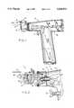
- FIG. 1is a pictorial view of a surgical handpiece of a kind usable as a powered sagittal or oscillating saw, and including a chuck and blade construction embodying the present invention.
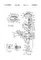
- FIG. 2is an enlarged central cross-sectional view, in elevation, of a fragment of FIG. 1 handpiece showing a chuck and blade embodying the invention and a drive structure therefor, as supported in a forward portion of the handpiece of FIG. 1.
- FIG. 3is a top view of the chuck and blade structure of FIG. 2.
- FIGS. 4 and 4Aare enlarged central cross-sectional views substantially taken on the line 4A--4A of FIG. 3 and respectively showing partly and fully inserted blade positions corresponding to FIGS. 5D and 5E.
- FIGS. 4B and 4Care enlarged central cross-sectional views substantially taken on the line 4B--4B of FIG. 5D and line 4C--4C of FIG. 5E respectively.
- FIGS. 5A-5Eare corresponding reduced cross-sectional views substantially taken on the line 5--5 of FIG. 4A with the blade at successive positions of insertion in the chuck.
- FIG. 6is an exploded pictorial view of the FIG. 1 chuck.
- FIG. 6Ais a pictorial view of the chuck top member of FIG. 6 but oriented upside down (as if rotated from FIG. 6 about a horizontal axis in the plane of the page).
- FIG. 7is a fragmentary sectional view taken substantially on the line 7--7 of FIG. 2.
- FIG. 8is an enlarged rear elevational view of the chuck substantially as taken on the line 8-8 of FIG. 3, with a blade inserted.
- FIG. 9is a front elevational view of the chuck of FIG. 8, with no blade inserted.
- FIG. 1discloses a powered surgical handpiece 10 which provides a typical environment for a chuck 11 and blade 12 more specifically embodying the invention.
- the handpiece 10may be of the type including a housing 13 enclosing a motorized drive assembly 14 of any convenient type schematically indicated in FIG. 2.
- the motorized drive assembly 14typically includes a drive motor M powered from a power source P through a switch S in turn actuated by a trigger T.
- the power source Pis electric, although other energy sources (for example, compressed air) are contemplated.
- the motor Mdrives a rotatable shaft 15, rotatably supported by suitable bearings, as at 16, supported by the housing 13.
- the forward end of the shaft 15carries an axially extending but eccentrically located drive pin 20 fixed thereon and in turn carrying a bearing 21 axially fixed thereon.
- a hollow extension 22Fixed to and extending forward from the housing 13 is a hollow extension 22, which is blind at its forward end but has coaxially spaced top and bottom through bores 23 and 24.
- An axial sleeve 25is press fitted down into the top bore 23 and has a radial flange 26 resting atop the extension 22.
- a blind bottomed bushing 27is press fitted up into the bottom bore 24 coaxially of the sleeve 25.
- the chuck 11includes a central depending shaft 31 supported for pivotal movement about its longitudinal axis (vertical in FIG. 2) by the sleeve 25 and bushing 27.
- the shaft 31has maximum and minimum diameter portions at the top and bottom thereof which are respectively rotatably supported by the sleeve 25 and bushing 27.
- the maximum diameter portion of the shaftis annularly grooved to receive an O-ring 32 (FIG. 2) which seals against the sleeve 25.
- the O-ring 32 and blind bushing 27seal the interior of the housing extension 22.
- An intermediate portion 34 of the shaft 31 disposed just below the sleeve 25has fixed thereto the forward (leftward) end of a link 35.
- the rearward (rightward) end of the link 35forms a fork 36 (FIG. 7).
- the fork 36has a laterally spaced pair of rearwardly extending tines 37.
- the tines 37snugly receive laterally therebetween the outer race of the bearing 21 carried by the eccentric drive pin 20.
- the opposed surfaces of the tines 37are vertical and extend above and below the central axis of the rotating shaft 15 sufficiently to maintain contact with the outer race of the bearing 21 as it moves on a vertical plane, through the circular orbit of the eccentric pin 20, as the pin orbits in response to rotation of the shaft 15.
- the chuck shaft 31in its intermediate portion 34 may be provided with oppositely facing flats 40.
- the forward end of the link 35receives the intermediate portion 34 of the shaft 31 in a broached, vertical, through hole 41 provided with corresponding flats 42.
- the hole 41 in the forward end of the link 35is thus sized and shaped to receive the intermediate portion 34 of the shaft 31 vertically therethrough in fixed, press fitted, and positive driving relation.
- the apparatusis conventional and is disclosed as a typical environment for the chuck 11 and blade 12 more specifically embodying the invention.
- the desired oscillating motionmay be imparted to the chuck 11 and blade 12 by other means than the link 35 and orbiting eccentric 20 discussed above, although the disclosed link and eccentric structure discussed above provide an effective yet economical structure for imparting the desired oscillatory movement to the chuck 11 and blade 12.
- the chuck 11comprises facing top and bottom casing members 50 and 51 (FIGS. 4 and 6).
- the bottom casing member 51is fixed centrally atop, and preferably integral with, the shaft 31.
- the casing members 50 and 51have the same outline in top plan view.
- the forward and rearward ends 52 and 53respectively are convexly rounded and connected by longitudinal sides 54 which are flatted and parallel.
- the top member 50is similar.
- the chuck 11has a horizontal, longitudinal, preferably rectangular cross section, forward opening slot 55 (FIG. 4) in which the rear end portion of the blade 12 is received as hereafter discussed.
- the slot 55is formed by a corresponding longitudinal, rectangular cross section groove 56 (FIG. 6A) extending centrally in the bottom face 60 of the top member 50.
- the groove 56opens through the front end 52' of the top member 50.
- the groove 56may open through the rear end 53' for convenience in machining.
- the groove 56has side walls 62 connected by a central flat 61 depressed from but parallel to the plane of the bottom face 60.
- the side walls 62 of the groove 56are parallel and extend forwardly/rearwardly of the top chuck member 50 and here are perpendicular to the groove central flat 61 and the bottom face 60.
- pins 63Two projections, here pins 63 (FIG. 6A), fixedly depend from the central flat 61 near the rear end 53' of top member 50 and are spaced between the groove side walls 62 and the front rear center line of the top member 50.
- the pins 63may readily be fixed to the top member 50 by press fitting into vertical blind holes (not shown) in the top member 50.
- the pins 63extend about half the depth of the slot 55 (FIG. 4A).
- the front edges 65 (FIG. 6A) of the side walls 62 of the groove 56 in the top member 50are rounded or bevelled to facilitate entry of the blade 12 into the slot 55 defined by the groove 56 and to reduce subsequent stress of the blade 12 bearing thereupon.
- the bottom face 60 of the top member 50has laterally opposed, semicircular notches 66 which open toward each other across the groove 56, through the respective groove side walls 62, and extend vertically partway the depth of the groove side walls 62.
- the laterally opposed notches 66are here offset slightly to the rear along the groove 56 but are forward of the pins 63.
- the notches 66define diametrally opposed chordal portions of an imaginary circle laterally centered on the top member 50.
- the groove 56may be thought to define a laterally opposed pair of side bulkheads 67 (FIG. 6A).
- the side bulkheads 67thus are flush with the sides 54' of the top member 50 and define the bottom face 60 and side walls 62.
- the bevels 65 and notches 66are in the side bulkheads 67.
- a sacrificial ridge 68(FIG. 6A) depends from the bulkheads 67 on each side of the top member 50.
- Each ridge 68is flush with the corresponding outer side 54' of the top member 50 and extends the front-rear length thereof.
- the ridges 68here extend along the outside perimeter of the respective notches 66.
- the ridges 68are here of substantially rectangular cross section.
- the cross section of the ridges 68is very small compared to the cross section of the corresponding bulkheads 67.
- the ridges 68are sized to melt down during electron beam welding of the top member 50 to the bottom member 51 to weld the same together face to face.
- the top 71 (FIG. 6) of the top member 50tapers upward toward an upstanding, cylindrical, circular fence 72 (FIG. 6).
- the fence 72surrounds an upward facing recess 73 having a flat bottom 74 (FIGS. 6 and 4).
- the fence 72is substantially centered atop the top member 50.
- a vertical hole 75extends down through the top member 50, as seen in FIGS. 4 and 6A.
- the hole 75is centered laterally between the bulkheads 67 but is offset somewhat rearwardly on the top member 50.
- the hole 75indeed has its center somewhat rearward of the center of the notches 66 but forward of the pins 63.
- the bottom portion of the hole 75is enlarged in diameter to form a downward facing step 76 (FIG. 4) and a corresponding downward opening recess 77.
- the recess 77opens through the central flat 61 of the top member 50.
- the top of the hole 75opens through the flat bottom 74 of the upward facing recess 73 bounded by the fence 72 and is offset rearwardly in the recess 73.
- the bottom member 51has a top face 80 (FIG. 6) in a plane perpendicular to the longitudinal axis of the shaft 31, and hence oriented horizontally in FIG. 6.
- the top face 80is laterally flanked by coplanar flats 81 which extend forward-rearward along the respective sides 54 of the bottom member 51.
- the flats 81are offset downward from the plane of the top face 80 by laterally outward facing steps 82.
- the height of the steps 82is less than the height of the side walls 62 of the bulkheads 67 of the top member 50, by an amount corresponding to the height of the blade receiving slot 65 (FIG. 9) of the chuck 11.
- the flats 81are horizontally sized to snugly receive thereon the respective bulkheads 67 of the top member 50 as seen for example in FIG. 9. This prevents lateral movement of the top member 50 with respect to the bottom member 51 during electron beam welding together of the members 50 and 51.
- the meltdown of the ridges 68 on the top member 50results in face-to-face engagement of the bottom face 60 (the bottom of the bulkheads 67) of the top member 50 with the upward facing flats 81 of the bottom member 51 as seen in FIG. 9.
- a shallow, circular, cylindrical recess 83is sunk in the top face 80 of the bottom member 51 and is slightly offset to the rear therein as seen in FIG. 6.
- the laterally opposed, semicircular notches 66 in the underside of the bulkheads 67 of the top member 50over-lie the laterally opposed portions of the recess 83 in the bottom member 51, which portions extend laterally into the flats 81 of the bottom member 51.
- the semicircular notches 66accommodate laterally opposed top portions of the shoe cover 86, in the assembled chuck 11.
- the recess 83 and flats 81leave the top face 80 in the form of two semi-circular upward facing surfaces of which the front is somewhat wider in a frontrear direction than the rear.
- the recess 83contains, in ascending order, a compression spring in the form of a resilient wave washer 84 (FIGS. 4A and 6), a disk-like shoe 85, and an inverted cup-shaped shoe cover 86.
- the cup-shaped shoe cover 86has a flat top end wall 87 (FIGS. 6) of circular shape from which depends an annular peripheral wall 88.
- the height of the shoe cover 86corresponds to the depth of the recess 83.
- the shoe cover 86is press fitted fixedly into the recess 83, its top wall 87 flush with the top face 80 of the bottom member 51.
- the bottom of the peripheral wall 88may rest on the bottom of the recess 83.
- the peripheral wall 88 of the shoe coveris on its outer face provided with an axially and radially narrow annular ridge 91 which snugly engages the side wall of the recess 83 in press fit relation therewith.
- the shoe cover 86 and the bottom of the recess 83define a chamber in which the wave washer 84 and the overlying shoe 85 are housed in radial clearance, vertically movable relation.
- the wave washer 84resiliently presses the shoe 85 upward against the top end wall 87 of the shoe cover 86 as shown in FIG. 4.
- the shoe 85comprises a circular disk 92 (FIG. 6) fixedly supporting a laterally spaced pair of ramps 93.
- the ramps 93are offset somewhat to the rear on the upper face of the disk 92 and are laterally spaced on opposite sides of the front-rear centerline of the disk.
- the ramps 93are preferably identical and each has a relatively shallow, forward facing and downward extending slope 94 which occupies most of the length of the ramp 93, and a relatively short, horizontal top 95.
- the top wall 87 of the shoe cover 86is pierced by laterally spaced, forward-rearward extended slots 96 (FIG. 6) sized and located to allow the ramps 93 to extend upward therethrough with sufficient horizontal clearance as to allow the disk 92 of the shoe 85 to move up and down within the shoe cover 86.
- the outside diameter of the disk 92is slightly less than the inside diameter of the shoe cover peripheral wall 88, so as not to restrict such up and down movement.
- Different vertical positions of the shoe 85 under the top 87 of the shoe cover 86are seen for example in FIGS. 4 and 4A, and in FIGS. 4B and 4C. In their uppermost position (for example in FIG. 4B), the ramps 93 extend almost up to the central flat 61 of the upper member 50, being spaced therefrom by less than the thickness of the thinnest blade 12 intended to be chucked in the chuck 11.
- the depending pins 63 of the top member 50are each forward-rearward aligned with a corresponding ramp 93 and slot 96.
- the bottom of the recess 83(FIGS. 4 and 6), the disk 92, and the shoe cover top wall 87 have coaxially aligned holes 100, 101 and 102 respectively.
- the holes 100-102are offset somewhat rearward on their respective members and are all in coaxial alignment with the hole 75 and recess 77 in the top member 50.
- the holes 101 and 102are of diameter less than the hole 75 but of diameter greater than the hole 100.
- the holes 101 and 102are through holes.
- the hole 100although axially much longer (deeper) than the holes 101 and 102, is blind as seen in FIG. 4.
- the holes 100-102are offset somewhat rearward of the central axis of the shaft 31, and are located laterally between the ramps 93, slots 96 laterally and forward of the pins 63.
- a locking spindle 105(FIGS. 4 and 6) comprises, in sequence downwardly, an enlarged cylindrical head 106, a radially outward extending flange 107, an unlocking segment 108 of substantially reduced diameter, a locking segment 109 of intermediate diameter, and a shank 110.
- the shank 110is here of diameter between that of the segments 108 and 109.
- the elements 106-110are coaxial and preferably are all cylindrical and of circular cross section.
- a coil compression spring 114is received with clearance in the blind hole 100 and can expand and be compressed axially in such hole 100.
- the shank 110is snugly but vertically slidably received in the hole 100 atop the spring 114.
- the holes 101 and 102 in the shoe 85 and shoe cover 86are sized to receive loosely therethrough the segments 108 and 109 and the shank 110 of the locking spindle 105, as seen in FIG. 4.
- the head 106 and flange 107 of the locking spindle 105substantially exceed the diameter of the holes 101 and 102. However, the head 106 and flange 107 are of diameter to be snugly but vertically slidably received in the hole 75 and recess 77 in the top member 50.
- the flange 107(FIG. 4A) is of diameter larger than the hole 75 so as to coact with the step 76 to prevent the locking spindle 105 from escaping upward through the top member 50, despite the upward urging of the partially compressed compression spring 114.
- the flange 107traps the locking spindle 105 within the chuck 11.
- the locking spindle 105is free to move up and down in the chuck 11 until the flange 107 collides with either the step 76 or the top end wall 87 of the shoe cover 86 (assuming no blade 12 is in place in the chuck).
- the top of the spindle head 106In its uppermost position, the top of the spindle head 106 is spaced slightly below the top of the fence 72 (FIG. 4A). In this uppermost position, the top of the locking spindle head 106 spaced well above the bottom 74 of the recess 73 defined by the fence 72. In this way, the fence 72 and spindle head 106 cooperate to allow intended pushing down of the locking spindle 105, from its FIG. 4A position toward its FIG. 4 position, by use of a thumb or finger, but to prevent accidental (unintended) pushing down of the locking spindle 105 when the palm of the user is pressed against the top of the chuck 11, as when a surgical assistant passes the handpiece 10 to a surgeon while grasping it by means of the chuck.
- the blades 12(FIG. 3) to be used with the chuck 11 include a cutting portion 121 remote from the chuck and typically being formed as a set of cutting teeth 122. Further, the blades 12 each have a mounting portion 123 (FIGS. 4 and 5A) to be received in the chuck 11. While the blades useable with the chuck 11 may take a variety of forms, in accord with their particular cutting task, and may thus differ in their size and shape outside the mounting portion 123 thereof, and indeed may even differ in the thickness of the mounting portion 123 thereof, up to a maximum thickness which can be received in the chuck slot 55, a typical blade 12 is here shown for purposes of illustration.
- the typical blade 12 here shownis of flat metal (preferably the relatively hard grade of stainless steel typically used for surgical saw blades), and is of elongate, generally rectangular plan, with the teeth 122 at the forward end thereof and the mounting portion 123 at the rearward end thereof.
- the mounting portion 123 of the blade 12comprises parallel opposed side edges 124 (FIG. 5A) snugly but slidably received between the side walls 62 of the slot 55. It is desirable that, as seen in FIG. 5E, the width of the blade mounting portion 123 is very nearly as great as the width of the slot 55 into which it is rearwardly slidably receivable. It is also desirable that the side edges 124 be long, e.g. nearly as long as the slot 55. This snug but slidable contact over most of the length of the groove 56 prevents rocking of the blade 12 from side to side with respect to the chuck 11 during cutting, so that when the chuck 11 oscillates, horizontally, such motion is imparted to a blade 12 therein.
- the rear end 125 of the blademeets the side edges 124 at rounded or beveled corners 128 (FIG. 5A) to ease insertion of the blade 12 rearwardly into the slot 55.
- Integral with and extending rearward from the rear end 125 of the bladeis rounded end nose 120 (FIGS. 5E and 6) centrally divided into a pair of laterally close-spaced nose means, or tines, 126 spaced by a narrow central slit 127.
- the nose 120is narrow compared to the width of the blade 12.
- the nose 120is longitudinally short compared to the width of the mounting portion 93 of the blade 12.
- the slit 127is of dumbbell shape, having an opposed pair of front notches and an opposed pair of rear notches here defined by respective circular front and rear parts 132 and 133, connected by a laterally narrower but longer neck 134.
- the front and rear parts 132 and 133respectively comprise second and first widenings of the slit 127.
- the widening 133defines opposed first and second safety locking means (defined by said opposed rear notches) and the widening 132 defines opposed first and second final locking means (defined by said front notches), the locking means here being formed by the above-mentioned notches.
- the open rear mouth 131 of the slit 127is bevelled or rounded.
- the mouth 131 and neck 134are sized to pass therethrough the unlocking segment 108 of the spindle 105 but not the locking segment 108, as seen in FIGS. 5B and 5D.
- the circular parts 132 and 133are sized to snugly receive the locking spindle 109 of the spindle 105 as seen in FIGS. 5C and 5E therein.
- the slit 127is bounded along one side edge by a safety peninsula at the mouth 131, a locking peninsula at the neck 134, a first bay at the rear slit part 133 and a second bay at the front slit part 132, wherein such one slit side edge may be termed a mounting edge comprising such safety peninsula, first bay, locking peninsula and second bay.
- Across the slit 127is the opposite slit edge (second mounting edge) wherein the opposed locking peninsula may be said to define a final lock means and the opposed safety peninsulas a safety lock means.
- the blades 12may be formed conventionally from stainless steel sheet stock, for example, by stamping and setting and hardening the teeth.
- the parts of the chuck 11are machined, or otherwise formed in any convenient manner, preferably from stainless steel stock.
- the resulting chuck parts shown in FIG. 6are then assembled. More particularly, and most easily with the parts turned upside down, the shoe 85 and wave washer 84 are placed in the open end of the shoe cover 86 with the ramps 93 extending through the slots 96.
- the thus loaded shoe cover 86has its peripheral wall 88 press fitted into the recess 83 in the bottom member 51. This traps the wave washer and shoe 85 between the top end wall 87 of the shoe cover and the bottom of the recess 83 in the bottom member 51, as seen for example in FIG. 4.
- the resultant assemblycan then be turned to the upright position shown in the drawings.
- the coil spring 114 and the shank 110 of the spindle 105can then be dropped down through the holes 101 and 102 (FIG. 4) and into the blind hole 100 in the bottom member 51.
- the chuck top member 50with its fixed dependent pins 63, can then be placed atop the bottom member 51, while the hole 75 and recess 77 in the top member 51 respectively receive the head 106 and flange 107 of the spindle 105.
- electron beam weldingmelts down the sacrificial ridges 68 in the top member 50 to weld the top member bulkheads 67 atop the bottom member flats 81 (FIGS. 6 and 9). This completes assembly of the chuck 11 in its condition of FIGS. 4A and 9).
- the top and bottom members 50 and 51thus become a one-piece unit and define the rectangular cross section, blade receiving slot 55 (FIGS. 4 and 9).
- the assembled chuck 11can then be pivotally mounted on the extension 22 on the front end of the handpiece 10. More particularly, with the sleeve 25 (FIG. 2) fixed in the top bore 23 of the extension 22, the chuck shaft 31 is slid downward through the sleeve 45 until the chuck bottom member 51 seats firmly on the flange 26 and the intermediate portion 34 is located below the sleeve 25.
- the link 35is predisposed in the hollow interior of the extension 22. As the chuck 11 is moved downward toward the extension 22 and the chuck shaft 31 slides downward through the sleeve 25, the lower end of the shaft 31 is guided through the hole 41 in the forward end of the link 35.
- a conventional tubular mandrel not showncan be inserted upward through the open bottom bore 24 to receive the bottom end of the shaft 31 and press the forward end of the link 35 onto the intermediate portion 34 of the shaft 31, with the flats 42 and 40 of the link 35 and shaft intermediate portion 34 opposed. The mandrel can then be withdrawn and the blind bushing 27 pressed upward into the bore 24 and over the bottom portion of the shaft.
- the groove in the upper portion of the chuck shaft 31is provided with a suitable seal, such as O-ring 32 to bear against the interior surface of the sleeve 25 and effect a seal thereagainst while allowing horizontal pivoting of the chuck 11.
- a suitable sealsuch as O-ring 32 to bear against the interior surface of the sleeve 25 and effect a seal thereagainst while allowing horizontal pivoting of the chuck 11.
- the closed end bushing 27prevents entry of foreign material past the bottom of the shaft into the interior of the extension 22.
- the assembly of the extension 22 on the handpiece housing 13 and the location of the bearing 16 and shaft 15, as well as the remaining components of the handpiece,can be conventional and requires no further comment.
- a family of different bladescan be used with a given chuck as long as the mounting portions 123 of all the blades conform to the dimensions of the chuck slot 55 and locking spindle 105 therein.
- bladesmay differ in thickness, even in the mounting portion 123, as long as the blade thickness in the mounting portion 123 does not exceed the effective height of the slot 55.
- blade thicknesswas in the range of 0.025 inch to 0.050 inch.
- the recess 83 in the bottom member 51is preferably deep enough to allow the ramps 93 to be pushed down flush with the top 87 of the shoe cover 86 and the top face 80 of the bottom member 51, i.e. with the bottom of the slot 55.
- bladesmay differ in plan, as to both shape and size in their portions outside the chuck, but with their mounting portions 123 being substantially the same.
- a blade 12is fixed in the chuck as follows. The mounting portion 123 of the blade is pushed rearward into the chuck slot 55.
- Initial entry of the blade into the chuck slot 55is made easy by the fact that the first entering portion of the blade, namely the nose 120 is small in height and width compared to the chuck slot 55 which it is to enter.
- the nose 120initially guides the blade 12 easily into the slot 55. Thereafter, the wider rear end 125 of the blade 12 enters the slot 55. This entry is aided by the rounded corners 128 at the rear end 125 of the blade and by the beveled edges 65 at the front end of the slot 55.
- Rearward travel of the blade 12is positively stopped when the blade is only partway (here about halfway) into the chuck, due to collision of the rear end of the nose 120 with the locking segment 109 of the spindle 105 (as seen in FIG. 5A).
- the locking segment 109is of diameter greater than the width of the blade mouth 131 and so positively blocks further entry of the blade 12 into the chuck 11.
- the blade 12is quite loose in the chuck 11, and can pivot with respect to the chuck horizontally and vertically (can yaw and pitch). By far the greater portion of the mass of the blade 12 is outside the chuck.
- the blade 12very easily falls out of the chuck 11 in normal handling of the handpiece 10, if by operator error the blade is left in its FIG. 5A position.
- the operatorTo insert the blade 12 beyond its FIG. 5A position, the operator must depress the spindle 105, from its FIG. 4A position, by downward finger or thumb pressure on the top of the head 106, preferably downward beyond its FIG. 4 position so that the top of the locking segment 109 is flush with or somewhat below the top wall 87 of the shoe cover 86. In this way, the wide locking segment 109 is out of the way of the nose 120 of the blade.
- the mouth 131is wide enough to accept the unlocking segment 108 of the spindle, allowing the blade to be pushed to its FIG. 5C position.
- the distance the blade travels from its FIG. 5A position to its FIG. 5C positionis small and is approximately the diameter of the locking segment 109.
- the spring 114will immediately raise the locking spindle 105 up through its FIG. 4 position to its uppermost FIG. 4A position, causing the locking segment 109 to lodge in the rear circular part 133 of the slit 127 as shown in FIG. 5C.
- the blade 12is taken from a condition where it will fall freely out of the chuck 11 without harm, to a condition in which it is positively locked within the chuck.
- the FIG. 5C positionmay thus be termed a safety, or safety locking position because the blade cannot be accidentally removed from the chuck although it is not yet in a position of use within the chuck.
- the blademay thus be said to have a safety locking portion comprising the slit part 133.
- the bladecan pitch freely up and down with respect to the chuck, which will make apparent to an operator that the blade 12 is still not fully chucked.
- the blade rear end 125firmly abuts the depending pins 63 of the chuck top member 50 to positively prevent further entry into the chuck while eliminating any significant rearward stress on the locking spindle 105 during cutting.
- the blademay thus be said to have a final locking portion comprising the slit part 132 side edges 124 of the blade abut substantially more than half the entire length of the side walls 62 of the groove 55, which positively prevents significant yawing of the blade with respect to the chuck during operation and without placing high unit pressures on blade edges 124.
- the rear end 125 of the rearward moving blade 12after passing its safety position of FIG. 5C, rides up the slopes 194 of the ramps 193 (FIGS. 4B and 5D) and is thereby pushed up against the top 61 of the slot 55 of the chuck 11.
- the rear end 125 of the bladecontinues further rearwardly along the slopes 94 of the ramps 93, depressing the ramps 93 against the force of the wave spring 84, as seen in the transition from FIG. 4B to FIG. 4C. Further insertion of the blade 12 causes it to cover the tops 95 of the ramps 93 (FIGS. 4C and 5E).
- the wave spring 84acts strongly enough through the tops 95 of the ramps 93 to firmly hold the parts of the blade 12 to the rear (the nose 120 and rear end 125) and front thereof, and hence the entire chucked mounting portion 123 of the blade 12, flat against the top 61 of the slot 55 of the chuck 11 (FIGS. 4A, 4C and 8).
- the thus fully chucked blade 12thus strongly resists any tendency to pitch, with respect to the chuck 11, during use.
- Forward withdrawal of the blade 12 from the chuck 11, after use,is by a reversal of the above steps required to chuck the blade. More particularly and briefly stated, the operator applies his thumb or forefinger to the top of the spindle head 106 to push same from its FIG. 4A position downward past its FIG. 4 position to disengage the locking portion 109 from the spindle from the blade 12. The operator can simply then pull the blade 12 forward out of the chuck 11. Thereafter, the operator can release the spindle 105, allowing it to rise back to its FIG. 4A position.
- the chuck 11is able to chuck blades of a range of thicknesses, for example, at least twice as thick as the blade 12 here shown, and if desired a somewhat thinner blade than the blade 12 here shown.
- one set of blades constructed according to the inventionranged in thickness from about 0.025 inch to about 0.05 inch with the height of the slot 55 being about 0.055 inch.
- the handpiece 10With a blade 12 installed in the chuck 11, the handpiece 10 can be actuated conventionally to produce the desired oscillating or sagittal motion of the chuck and hence of the blade teeth, such motion being schematically indicated by the arrow A in FIG. 3.
- pressing of the trigger T by the operatorcauses the switch S to apply power from the power source P to the motor M to rotate the shaft 15 and orbit the eccentric drive pin 20 and thereby laterally swing the link 35 back and forth horizontally to cause a small arcuate oscillation in a horizontal plane of the chuck 11 and blade 12.
- the lateral swing of the saw blade 12is typically in the range of 3 to 6 degrees, for example, 4.5 degrees.
- the chuck 11has only a single slot 55 opening to the outside but yet can accommodate blades of differing thickness and still provide the ability to make precision cuts, such as those encountered in total knee arthroplasty.
- the blade 12is positively locked in the chuck 11, although not yet fully inserted thereinto. If the blade has not been inserted far enough into the chuck to be positively locked in its FIG. 5C safety lock position, then the blade is still so loose in the chuck that it is immediately apparent that it is not chucked and it is not ready for use. Indeed, in that condition, if the chuck is angled downward, the blade will simply fall freely from it. Prior to reaching the safety lock position of FIG. 5C, there is no intermediate range of insertion in which the blade is frictionally retained sufficient to mislead a user into thinking that the blade is fully inserted or locked in the chuck or in a position of use.
- the relative location of the locking spindle 105 and ramps 93 and the relative location of the spindle engaging rear end of the nose 120 with respect to the ramp engaging rear edge 125 of the bladeprevents any significant gripping of the blade by the chuck until the blade has been inserted enough as to be in or past its FIG. 5C safety lock position.
Landscapes
- Health & Medical Sciences (AREA)
- Surgery (AREA)
- Engineering & Computer Science (AREA)
- Life Sciences & Earth Sciences (AREA)
- Biomedical Technology (AREA)
- Nuclear Medicine, Radiotherapy & Molecular Imaging (AREA)
- Oral & Maxillofacial Surgery (AREA)
- Dentistry (AREA)
- Mechanical Engineering (AREA)
- Heart & Thoracic Surgery (AREA)
- Medical Informatics (AREA)
- Molecular Biology (AREA)
- Animal Behavior & Ethology (AREA)
- General Health & Medical Sciences (AREA)
- Public Health (AREA)
- Veterinary Medicine (AREA)
- Surgical Instruments (AREA)
Abstract
Description
Claims (33)
Priority Applications (1)
| Application Number | Priority Date | Filing Date | Title |
|---|---|---|---|
| US08/091,347US5439472A (en) | 1991-01-11 | 1993-07-14 | Surgical handpiece chuck and blade |
Applications Claiming Priority (3)
| Application Number | Priority Date | Filing Date | Title |
|---|---|---|---|
| US64002891A | 1991-01-11 | 1991-01-11 | |
| US07/989,975US5263972A (en) | 1991-01-11 | 1992-12-11 | Surgical handpiece chuck and blade |
| US08/091,347US5439472A (en) | 1991-01-11 | 1993-07-14 | Surgical handpiece chuck and blade |
Related Parent Applications (1)
| Application Number | Title | Priority Date | Filing Date |
|---|---|---|---|
| US07/989,975ContinuationUS5263972A (en) | 1991-01-11 | 1992-12-11 | Surgical handpiece chuck and blade |
Publications (1)
| Publication Number | Publication Date |
|---|---|
| US5439472Atrue US5439472A (en) | 1995-08-08 |
Family
ID=27093463
Family Applications (2)
| Application Number | Title | Priority Date | Filing Date |
|---|---|---|---|
| US07/989,975Expired - LifetimeUS5263972A (en) | 1991-01-11 | 1992-12-11 | Surgical handpiece chuck and blade |
| US08/091,347Expired - LifetimeUS5439472A (en) | 1991-01-11 | 1993-07-14 | Surgical handpiece chuck and blade |
Family Applications Before (1)
| Application Number | Title | Priority Date | Filing Date |
|---|---|---|---|
| US07/989,975Expired - LifetimeUS5263972A (en) | 1991-01-11 | 1992-12-11 | Surgical handpiece chuck and blade |
Country Status (1)
| Country | Link |
|---|---|
| US (2) | US5263972A (en) |
Cited By (63)
| Publication number | Priority date | Publication date | Assignee | Title |
|---|---|---|---|---|
| WO1997022303A1 (en)* | 1995-12-21 | 1997-06-26 | Minnesota Mining And Manufacturing Company | Orthopedic surgical device having a rotatable portion and lock |
| US5702415A (en)* | 1993-05-26 | 1997-12-30 | Stryker Corporation | Chuck and blade for powered medical handpiece |
| US5725530A (en)* | 1996-06-19 | 1998-03-10 | Popken; John A. | Surgical saw and methods therefor |
| US5735866A (en)* | 1996-09-19 | 1998-04-07 | Linvatec Corporation | Adjustable length saw blade |
| US5903983A (en)* | 1994-11-29 | 1999-05-18 | Milwaukee Electric Tool Corp. | Keyless clamp assembly for reciprocating tool |
| USD439334S1 (en) | 1998-10-26 | 2001-03-20 | Stryker Corporation | Handpiece for a surgical tool |
| US6209208B1 (en) | 1998-10-09 | 2001-04-03 | Milwaukee Electric Tool Corporarion | Keyless blade clamp mechanism |
| WO2002015799A1 (en)* | 2000-08-25 | 2002-02-28 | Nanxiang Gao | Sternum cutting apparatus |
| US6363617B1 (en) | 1999-04-07 | 2002-04-02 | Terry Frost | Guard for cast cutter |
| US6662698B2 (en) | 2002-01-02 | 2003-12-16 | Black & Decker Inc. | Saw blade clamp system |
| US6723101B2 (en)* | 1991-05-30 | 2004-04-20 | Synvasive Technology, Inc. | Method of surgically cutting a bone using a surgical saw blade |
| USD492412S1 (en) | 2003-03-07 | 2004-06-29 | De Soutter Medical Ltd. | Surgical saw blade |
| US20040163264A1 (en)* | 2003-02-21 | 2004-08-26 | Simonz John C. | Hand saw |
| US20040199167A1 (en)* | 1991-05-30 | 2004-10-07 | Fletcher Henry Hasbrouck | Surgical saw blade having at least one pair of opposed teeth shaped as right triangles |
| US6857348B1 (en)* | 1998-12-18 | 2005-02-22 | Black & Decker Inc. | Arrangement for clamping a saw blade |
| US20050075633A1 (en)* | 2003-10-02 | 2005-04-07 | Thomas Ross | Anterior cervical plate |
| US20050192585A1 (en)* | 2004-02-27 | 2005-09-01 | Medtronic, Inc. | Surgical saw collet with closed drive ring |
| US20050245935A1 (en)* | 2004-04-29 | 2005-11-03 | Casey Conor P | Surgical saw blade |
| US20060009796A1 (en)* | 2004-07-09 | 2006-01-12 | Steven Carusillo | Surgical sagittal saw and method of using same |
| US20060206100A1 (en)* | 2005-03-09 | 2006-09-14 | Brasseler Usa Medical Llc | Surgical apparatus and power module for same, and a method of preparing a surgical apparatus |
| US20060217729A1 (en)* | 2005-03-09 | 2006-09-28 | Brasseler Usa Medical Llc | Surgical apparatus and tools for same |
| US20070016238A1 (en)* | 2005-07-14 | 2007-01-18 | Joe Marietta | Surgical sagittal saw with quick release indexing head and low blade-slap coupling assembly |
| USD536791S1 (en) | 2005-03-09 | 2007-02-13 | Brasseler Usa Medical Llc | Tool hub |
| US20070034066A1 (en)* | 2002-10-31 | 2007-02-15 | Garcia Jaime E | Riving knife assembly for a dual bevel table saw |
| US20070083209A1 (en)* | 2005-09-23 | 2007-04-12 | Synvasive Technology | Transverse acting surgical saw blade |
| USD554256S1 (en) | 2005-03-09 | 2007-10-30 | Brasseler Usa Medical Llc | Tool hub |
| US20080027449A1 (en)* | 2006-07-28 | 2008-01-31 | Depuy Products, Inc. | Adapters to convert output motion of orthopaedic bone saws and bone drills |
| US20080190259A1 (en)* | 2004-10-19 | 2008-08-14 | Ulrich Bohne | Device for Fastening a Tool to a Drive Shaft of a Hand-Held Power Tool Driveable in an Oscillating Manner |
| US7587826B1 (en)* | 2006-01-17 | 2009-09-15 | John David Stutz | Hand held vibrating knife |
| USD603231S1 (en) | 2008-05-30 | 2009-11-03 | Synvasive Technology, Inc. | Surgical saw blade hub |
| US20090312779A1 (en)* | 2008-06-11 | 2009-12-17 | Medtronic Ps Medical, Inc. | Surgical Cutting Instrument With Near-Perimeter Interlocking Coupling Arrangement |
| US20090312761A1 (en)* | 2008-06-11 | 2009-12-17 | Medtronic Ps Medical, Inc. | Surgical Cutting Instrument with Dual Surface Interlocking Coupling Arrangement |
| US20100292701A1 (en)* | 2009-05-12 | 2010-11-18 | Synvasive Technology, Inc. | Surgical saw blade device and system |
| US20110046627A1 (en)* | 2009-08-21 | 2011-02-24 | Chong Chol Kim | Reciprocating Surgical Saws With Blade Assemblies |
| US20110106092A1 (en)* | 2009-11-02 | 2011-05-05 | Synvasive, Inc. | Bone positioning device and method |
| US20110207079A1 (en)* | 2010-01-27 | 2011-08-25 | Rubin Jerry A | Coated surgical and dental implements and implants with superior heat dissipation and toughness |
| US20110209888A1 (en)* | 2010-02-27 | 2011-09-01 | C Enterprise (Hk) Limited | Hand-held oscillatory power tool with two-axis tool mounting |
| US20110315413A1 (en)* | 2010-06-25 | 2011-12-29 | Mako Surgical Corp. | Kit-Of Parts for Multi-Functional Tool, Drive Unit, and Operating Members |
| US20120170976A1 (en)* | 2009-07-01 | 2012-07-05 | Lvqian Cai | Working Head of Pendulum Tool and Converter |
| US8230607B2 (en) | 2008-05-09 | 2012-07-31 | Milwaukee Electric Tool Corporation | Keyless blade clamp for a power tool |
| US20120289963A1 (en)* | 2010-01-11 | 2012-11-15 | Legrand Bernard P | Surgical blade assembly |
| WO2012170459A3 (en)* | 2011-06-10 | 2013-05-02 | Tufts University | Sagittal saw |
| US8813373B2 (en) | 2007-09-14 | 2014-08-26 | Milwaukee Electric Tool Corporation | Blade clamp mechanism |
| US8858559B2 (en) | 2012-02-06 | 2014-10-14 | Medtronic Ps Medical, Inc. | Saw blade stability and collet system mechanism |
| USD716944S1 (en) | 2011-08-03 | 2014-11-04 | Synvasive Technology, Inc. | Surgical saw blade hub |
| CN104173091A (en)* | 2014-08-21 | 2014-12-03 | 舒捷医疗科技(苏州)有限公司 | Chuck structure of medical saw |
| US8920424B2 (en) | 2008-06-11 | 2014-12-30 | Medtronic Ps Medical, Inc. | Micro-saw blade for bone-cutting surgical saws |
| US8936597B2 (en) | 2012-02-06 | 2015-01-20 | Medtronic Ps Medical, Inc. | Deflectable finger connection feature on surgical saw blade |
| US9095352B2 (en) | 2009-11-02 | 2015-08-04 | Synvasive Technology, Inc. | Bone positioning device and method |
| US9168188B2 (en) | 2007-11-13 | 2015-10-27 | Orthopediatrics Corporation | Cast removal system |
| US9321112B2 (en) | 2011-05-18 | 2016-04-26 | Black & Decker Inc. | Power saw tool |
| US9707005B2 (en) | 2014-02-14 | 2017-07-18 | Ethicon Llc | Lockout mechanisms for surgical devices |
| US9899899B2 (en) | 2013-10-25 | 2018-02-20 | Black & Decker Inc. | Handheld power tool with compact AC switch |
| US10239135B2 (en) | 2013-03-06 | 2019-03-26 | De Soutter Medical Ltd | Surgical saw mount and blade |
| DE102018130381A1 (en) | 2018-11-29 | 2020-06-04 | Aesculap Ag | Surgical tool with effector holder |
| US11090061B2 (en) | 2005-09-10 | 2021-08-17 | Stryker Corporation | Surgical saw blade |
| US11160561B2 (en) | 2015-05-12 | 2021-11-02 | Stryker European Holdings I, Llc | Surgical sagittal blade cartridge with a guide bar |
| US11357644B2 (en) | 2011-10-24 | 2022-06-14 | Synvasive Technology, Inc. | Knee balancing devices, systems and methods |
| US11771475B2 (en) | 2020-10-07 | 2023-10-03 | Globus Medical, Inc. | Systems and methods for surgical procedures using band clamp implants and tensioning instruments |
| US11812973B2 (en) | 2018-03-06 | 2023-11-14 | Conmed Corporation | Sheathed surgical saw blade with bearings |
| USD1084334S1 (en) | 2022-06-22 | 2025-07-15 | Stryker European Operations Limited | Surgical blade cartridge |
| USD1084335S1 (en) | 2022-06-22 | 2025-07-15 | Stryker European Operations Limited | Surgical blade cartridge |
| US12419671B2 (en) | 2020-10-16 | 2025-09-23 | Globus Medical Inc. | Band clamps implants |
Families Citing this family (65)
| Publication number | Priority date | Publication date | Assignee | Title |
|---|---|---|---|---|
| US5263972A (en)* | 1991-01-11 | 1993-11-23 | Stryker Corporation | Surgical handpiece chuck and blade |
| US5382249A (en)* | 1991-05-30 | 1995-01-17 | Synvasive Technology, Inc. | Adjustable surgical blade |
| USD353888S (en) | 1993-06-15 | 1994-12-27 | Surgiquip, Inc. | Surgical saw |
| USD360946S (en) | 1994-02-18 | 1995-08-01 | Hall Surgical | Surgical saw blade hub |
| US5489285A (en)* | 1994-02-23 | 1996-02-06 | Hall Surgical, Div. Of Zimmer, Inc. | Surgical saw blade and clamp |
| USD362065S (en) | 1994-05-19 | 1995-09-05 | Hall Surgical, Div. Of Zimmer, Inc. | Surgical saw blade hub |
| US5553675A (en)* | 1994-06-10 | 1996-09-10 | Minnesota Mining And Manufacturing Company | Orthopedic surgical device |
| USD364463S (en) | 1994-06-10 | 1995-11-21 | Minnesota Mining And Manufacturing Company | Orthopedic surgical instrument |
| US5554165A (en)* | 1995-02-09 | 1996-09-10 | Hall Surgical, Div. Of Zimmer, Inc. | Surgical blade and hub |
| US5647133A (en)* | 1995-06-09 | 1997-07-15 | Black & Decker Inc. | Saw blade clamping arrangement for a power tool |
| US6295736B1 (en) | 1995-06-09 | 2001-10-02 | Black & Decker Inc. | Blade ejection mechanism for a saw blade clamping arrangement of a power tool |
| US7325315B2 (en)* | 1995-06-09 | 2008-02-05 | Black & Decker Inc. | Clamping arrangement for receiving a saw blade in multiple orientations |
| US6023848A (en)* | 1995-06-09 | 2000-02-15 | Black & Decker Inc. | Saw blade clamping arrangement for a power tool |
| US6944959B2 (en) | 1995-06-09 | 2005-09-20 | Black & Decker Inc. | Clamping arrangement for receiving a saw blade in multiple orientations |
| US6009627A (en)* | 1995-06-09 | 2000-01-04 | Black & Decker Inc. | Saw blade clamping arrangement for a power tool |
| EP0853464A4 (en)* | 1995-09-18 | 2001-02-07 | Exactech Inc | SURGICAL SAW WITH COMPENSATED OSCILLATORY MOVEMENTS |
| US5658304A (en)* | 1995-10-18 | 1997-08-19 | Linvatec Corporation | Wrenchless and adapterless collet system for surgical blades |
| USD379795S (en)* | 1995-11-13 | 1997-06-10 | Minnesota Mining And Manufacturing Company | Battery housing for an orthopedic surgical device |
| DE19547331A1 (en)* | 1995-12-19 | 1997-06-26 | Bosch Gmbh Robert | Electric hand machine tool |
| EP0810050B1 (en)* | 1996-05-23 | 2002-08-14 | Black & Decker Inc. | Saw blade clamping arrangement for a power tool |
| US6113618A (en)* | 1999-01-13 | 2000-09-05 | Stryker Corporation | Surgical saw with spring-loaded, low-noise cutting blade |
| US6656626B1 (en) | 1999-06-01 | 2003-12-02 | Porter-Cable Corporation | Cordless power tool battery release mechanism |
| DE10058894A1 (en)* | 2000-11-23 | 2002-06-06 | C & E Fein Gmbh & Co Kg | Tool, e.g. a cutter for cutting through sealed joints, has an attachment mechanism for connection to a drive shaft and a safety element that serves to tension a working part against a holder |
| US6514259B2 (en)* | 2001-02-02 | 2003-02-04 | Carnegie Mellon University | Probe and associated system and method for facilitating planar osteotomy during arthoplasty |
| US7547307B2 (en) | 2001-02-27 | 2009-06-16 | Smith & Nephew, Inc. | Computer assisted knee arthroplasty instrumentation, systems, and processes |
| US6729413B2 (en)* | 2001-08-24 | 2004-05-04 | Black & Decker Inc. | Power tool with battery pack ejector |
| DE10164081B4 (en)* | 2001-12-19 | 2012-01-26 | C. & E. Fein Gmbh | Oscillating tool with compensation section |
| US6875222B2 (en)* | 2002-03-12 | 2005-04-05 | Depuy Products, Inc. | Blade for resection of bone for prosthesis implantation, blade stop and method |
| US7833241B2 (en)* | 2002-11-12 | 2010-11-16 | Stryker Corporation | Surgical saw blade coupler |
| USD489823S1 (en) | 2003-01-14 | 2004-05-11 | Synvasive Technology, Inc. | Surgical saw blade hub |
| US7189239B2 (en)* | 2003-01-14 | 2007-03-13 | Synvasive Technology, Inc. A California Corporation | Saw blade having a prearranged hub section |
| FR2852223B1 (en) | 2003-03-11 | 2005-06-10 | Perception Raisonnement Action En Medecine | INSTRUMENT FOR TRACKING THE POSITION OF A CUTTING PLAN |
| US20040186493A1 (en)* | 2003-03-17 | 2004-09-23 | Mcwhorter Paul Jackson | Microkeratome cutting head assembly with single bevel cutting blade |
| US20050021037A1 (en)* | 2003-05-29 | 2005-01-27 | Mccombs Daniel L. | Image-guided navigated precision reamers |
| US7862570B2 (en) | 2003-10-03 | 2011-01-04 | Smith & Nephew, Inc. | Surgical positioners |
| US7764985B2 (en) | 2003-10-20 | 2010-07-27 | Smith & Nephew, Inc. | Surgical navigation system component fault interfaces and related processes |
| ATE495706T1 (en)* | 2003-11-14 | 2011-02-15 | Smith & Nephew Inc | ADJUSTABLE SURGICAL CUTTING SYSTEMS |
| CA2561493A1 (en) | 2004-03-31 | 2005-10-20 | Smith & Nephew, Inc. | Methods and apparatuses for providing a reference array input device |
| EP1737375B1 (en) | 2004-04-21 | 2021-08-11 | Smith & Nephew, Inc | Computer-aided navigation systems for shoulder arthroplasty |
| WO2006091704A1 (en)* | 2005-02-22 | 2006-08-31 | Smith & Nephew, Inc. | In-line milling system |
| US8137370B2 (en)* | 2005-11-02 | 2012-03-20 | Stryker Corporation | Powered surgical handpiece with improved latch mechanism and rotary to oscillating output drive |
| DE102005063015A1 (en)* | 2005-12-30 | 2007-07-05 | Robert Bosch Gmbh | Lifting saw with attachment device for a saw blade |
| US8608745B2 (en)* | 2007-03-26 | 2013-12-17 | DePuy Synthes Products, LLC | System, apparatus, and method for cutting bone during an orthopaedic surgical procedure |
| FR2924011A1 (en)* | 2007-11-26 | 2009-05-29 | Boutin Bourlon Internat Medica | Drunken saw for e.g. orthopedic application, has case mounted on body and maintaining axle and connecting fork in unified manner, where fork is connected to support axle of blade to transmit oscillation movement to blade |
| US20100186235A1 (en)* | 2009-01-26 | 2010-07-29 | Eric Davis Schwartz | Portable battery operated pipe cutter |
| EP2286659B1 (en)* | 2009-08-18 | 2018-05-30 | Robert Bosch GmbH | Power tool having an interchangeable blade assembly and method for interchanging the blade assembly |
| US8685028B2 (en) | 2009-08-21 | 2014-04-01 | Infinesse Corporation | Reciprocating surgical saws with blade assemblies |
| CN102335020B (en)* | 2010-07-15 | 2014-01-01 | 北京蒙太因医疗器械有限公司 | Medical powered fret saw |
| US9149923B2 (en)* | 2010-11-09 | 2015-10-06 | Black & Decker Inc. | Oscillating tools and accessories |
| DE102011005821A1 (en)* | 2011-03-18 | 2012-09-20 | Robert Bosch Gmbh | Tool clamping device |
| CN102884948B (en)* | 2011-07-22 | 2014-08-27 | 南京德朔实业有限公司 | Electric pruning shears |
| US9192390B2 (en)* | 2012-12-14 | 2015-11-24 | DePuy Synthes Products, Inc. | Surgical saw blade |
| CN103505259B (en)* | 2013-10-22 | 2015-12-23 | 重庆西山科技股份有限公司 | The goose saw head assembly of the removable saw blade assembly of orthopaedics |
| WO2015195615A1 (en)* | 2014-06-16 | 2015-12-23 | Robert Bosch Gmbh | Blade and blade attachment system for an oscillating tool |
| DE102015114028A1 (en)* | 2015-08-24 | 2017-03-02 | Wolfcraft Gmbh | Adapter system for fastening a tool to an oscillating drivable drive section |
| US10702283B2 (en)* | 2016-11-10 | 2020-07-07 | Biomedtrix, Llc | Radial saw blade and hub for osteotomy |
| WO2019046561A1 (en) | 2017-08-31 | 2019-03-07 | Smith & Nephew, Inc. | Computer-controlled remote power module for use with battery-controlled surgical tools |
| CN109512482B (en)* | 2017-09-20 | 2020-04-14 | 王力平 | Limiting sleeve trepan |
| US11154380B2 (en) | 2017-10-26 | 2021-10-26 | King Abdulaziz University | Dental restoration scalpel |
| USD931069S1 (en) | 2019-05-03 | 2021-09-21 | Tti (Macao Commercial Offshore) Limited | Blade |
| US11490898B2 (en) | 2019-10-18 | 2022-11-08 | Depuy Synthes Products, Inc | Surgical saw blade |
| CN110919106B (en)* | 2020-02-12 | 2020-06-19 | 北京罗森博特科技有限公司 | Cutting device for tail end of manipulator and manipulator |
| IE20230287A1 (en) | 2020-05-12 | 2024-11-20 | Mako Surgical Corp | Clamp guard |
| US11738398B2 (en) | 2020-11-18 | 2023-08-29 | Milwaukee Electric Tool Corporation | Accessory for an oscillating power tool |
| WO2024102642A1 (en)* | 2022-11-10 | 2024-05-16 | Peleton Surgical, Llc | Coupling mechanism for oscillating tool |
Citations (63)
| Publication number | Priority date | Publication date | Assignee | Title |
|---|---|---|---|---|
| US44823A (en)* | 1864-10-25 | Improvement in mode of securing bits in braces | ||
| US436804A (en)* | 1890-09-23 | roberts | ||
| US1048085A (en)* | 1910-06-11 | 1912-12-24 | Allison M Macfarland | Safety-razor. |
| US1064493A (en)* | 1912-06-29 | 1913-06-10 | Edward Kropat | Tool-handle. |
| US1125234A (en)* | 1912-06-18 | 1915-01-19 | Nagle Re Blade Knife Company | Pocket-knife. |
| US1413101A (en)* | 1920-08-27 | 1922-04-18 | Samuel J Cushing | Tool holder |
| US1448305A (en)* | 1921-07-09 | 1923-03-13 | Langbein Edward | Interchangeable-blade-operating knife |
| US1495675A (en)* | 1923-10-26 | 1924-05-27 | Sydna T Colt | Dental instrument |
| US1808239A (en)* | 1927-12-31 | 1931-06-02 | George A Logan | Combination tool |
| US1940855A (en)* | 1931-06-25 | 1933-12-26 | Friedman Hugo | Knife |
| US2557364A (en)* | 1948-06-15 | 1951-06-19 | Orthopedic Frame Co | Surgical saw blade |
| US2604130A (en)* | 1949-10-06 | 1952-07-22 | Henry Disston And Sons Inc | Detachable handle saw |
| US2649838A (en)* | 1949-05-11 | 1953-08-25 | Autopoint Co | Telescoping magnifying lens and handle |
| US2854981A (en)* | 1957-02-18 | 1958-10-07 | Orthopedic Frame Company | Surgical instrument |
| US3103069A (en)* | 1962-11-14 | 1963-09-10 | Orthopedic Equipment Co | Vacuumized surgical cast cutter |
| US3542097A (en)* | 1968-05-02 | 1970-11-24 | Singer Co | Chuck assembly for sabre saws |
| US3554197A (en)* | 1967-08-11 | 1971-01-12 | Desoutter Brothers Ltd | Portable power-operated saw |
| US3678934A (en)* | 1970-08-13 | 1972-07-25 | Stryker Corp | Power osteotome |
| US3703036A (en)* | 1971-05-03 | 1972-11-21 | Ralph Karubian | Separable connection means for reciprocating saw blades |
| US3750283A (en)* | 1970-11-09 | 1973-08-07 | S Hoffman | Blade attachment means for saber saw assembly |
| US3823473A (en)* | 1970-11-09 | 1974-07-16 | S Hoffman | Blade attachment means for saber saw assembly |
| US3852881A (en)* | 1973-06-11 | 1974-12-10 | Richards Mfg Co | Cutting blade for use with an oscillating cutting device |
| US3863339A (en)* | 1972-05-26 | 1975-02-04 | Stanley Tools Ltd | Retractable blade knife |
| US3901117A (en)* | 1970-11-09 | 1975-08-26 | Simon J Hoffman | Saber saw and blade therefor |
| US3905105A (en)* | 1973-01-08 | 1975-09-16 | Nat Res Dev | Saws and blades therefor |
| US3905374A (en)* | 1974-01-28 | 1975-09-16 | American Sterilizer Co | Knee osteotomy blade |
| US3927893A (en)* | 1974-01-11 | 1975-12-23 | Skil Corp | Collet assembly for a reciprocating tool |
| US3943934A (en)* | 1974-09-30 | 1976-03-16 | Minnesota Mining And Manufacturing Company | Quick release mechanism for surgical devices |
| US3952412A (en)* | 1975-03-28 | 1976-04-27 | Rhodes William A | Oscillatory saw |
| US3974868A (en)* | 1974-11-21 | 1976-08-17 | The Jacobs Manufacturing Company Limited | Hand tools |
| US3977289A (en)* | 1973-01-08 | 1976-08-31 | National Research Development Corporation | Saws and blades therefor |
| US4008720A (en)* | 1974-06-08 | 1977-02-22 | Paul Brinckmann | Blade with irrigation tubes |
| US4020555A (en)* | 1976-04-12 | 1977-05-03 | Pevrick Engineering Co., Inc. | Connecting mechanism for a saw blade |
| US4032747A (en)* | 1975-11-12 | 1977-06-28 | Clairol Incorporated | Thermal hair styling appliance having interchangeable attachments |
| USD245918S (en) | 1976-10-01 | 1977-09-27 | Zimmer, U.S.A. Inc. | Combination tibial resection and talar drill guide |
| US4064871A (en)* | 1976-05-11 | 1977-12-27 | Becton, Dickinson And Company | Device for making precise incisions for bleeding time testing and the like |
| US4106181A (en)* | 1976-08-09 | 1978-08-15 | American Safety Equipment Corporation | Quick release mechanism for oscillating saw blade |
| US4233737A (en)* | 1979-04-13 | 1980-11-18 | Poehlmann Paul W | Knife with removable blade |
| US4252121A (en)* | 1977-12-09 | 1981-02-24 | Arnegger Richard E | Separating device |
| US4386609A (en)* | 1979-12-17 | 1983-06-07 | Minnesota Mining And Manufacturing Company | Attaching assembly for an osteotomy saw blade |
| US4470196A (en)* | 1979-08-01 | 1984-09-11 | Hoffman Simon J | Holder for saber saw blade |
| US4528753A (en)* | 1982-12-08 | 1985-07-16 | Robert Bosch Gmbh | Reciprocating saw holder and housing |
| US4584999A (en)* | 1981-07-14 | 1986-04-29 | Arnegger Richard E | Saw blade with shallow section |
| US4617930A (en)* | 1984-05-16 | 1986-10-21 | Queen's University At Kingston | Blade stiffener |
| US4637391A (en)* | 1986-04-03 | 1987-01-20 | Schlein Allen P | Surgical saw blade |
| US4646440A (en)* | 1984-05-31 | 1987-03-03 | Decker John R | Replaceable blade knife |
| US4648182A (en)* | 1979-08-01 | 1987-03-10 | Hoffman Simon J | Holder for saber saw blade |
| US4694542A (en)* | 1986-02-14 | 1987-09-22 | Koppe Lou W | Foldable closure for flexible bags comprising flat sheet with integral axial hinge groove, lead in notch, and gripping aperture |
| US4711030A (en)* | 1986-05-05 | 1987-12-08 | Ruston Sr Robert B | Variable speed fillet knife |
| USD294734S (en) | 1985-11-19 | 1988-03-15 | Detsch Steven G | Forward cutting portion of a disposable surgical scalpel blade or the like |
| US4730952A (en)* | 1986-08-04 | 1988-03-15 | Wiley Edward R | Quick change mechanism for circular saw blades |
| US4736742A (en)* | 1986-04-03 | 1988-04-12 | Minnesota Mining And Manufacturing Company | Device for driving tools used in orthopedic surgery |
| US4739557A (en)* | 1985-03-09 | 1988-04-26 | Rems-Werk Christian Foll Und Sohne Gmbh & Co. | Saw blade for an electric compass- or keyhole-saw |
| US4768504A (en)* | 1985-05-07 | 1988-09-06 | Ender Hans G | Device for osteotomy |
| US4783886A (en)* | 1987-08-24 | 1988-11-15 | Koppe Lou W | Paper-laminated pliable closure for flexible bags |
| US4819334A (en)* | 1983-05-06 | 1989-04-11 | Minnesota Mining And Manufacturing Company | Orbital saw device |
| US4891884A (en)* | 1987-07-21 | 1990-01-09 | Philip Torbet | Hand holdable automatic bladed appliance for slicing, peeling and the like |
| US4899443A (en)* | 1987-10-31 | 1990-02-13 | Martor-Argentax E.H. Beermann Kg | Safety knife for cardboard and like materials |
| US4920646A (en)* | 1988-04-05 | 1990-05-01 | Grant Jerry L | Replaceable adjustment mechanism |
| USD317821S (en) | 1988-02-26 | 1991-06-25 | Tokyo Bi-Tech Laboratories, Inc. | Tongue depressor |
| US5122142A (en)* | 1990-09-13 | 1992-06-16 | Hall Surgical Division Of Zimmer, Inc. | Irrigating saw blade |
| US5133728A (en)* | 1990-01-05 | 1992-07-28 | Petersen Thomas D | Gall-resistant ribbed surgical saw blade |
| US5263972A (en)* | 1991-01-11 | 1993-11-23 | Stryker Corporation | Surgical handpiece chuck and blade |
Family Cites Families (1)
| Publication number | Priority date | Publication date | Assignee | Title |
|---|---|---|---|---|
| US3964163A (en)* | 1975-09-04 | 1976-06-22 | Minnesota Mining And Manufacturing Company | Surgical saw blade fastening means |
- 1992
- 1992-12-11USUS07/989,975patent/US5263972A/ennot_activeExpired - Lifetime
- 1993
- 1993-07-14USUS08/091,347patent/US5439472A/ennot_activeExpired - Lifetime
Patent Citations (63)
| Publication number | Priority date | Publication date | Assignee | Title |
|---|---|---|---|---|
| US44823A (en)* | 1864-10-25 | Improvement in mode of securing bits in braces | ||
| US436804A (en)* | 1890-09-23 | roberts | ||
| US1048085A (en)* | 1910-06-11 | 1912-12-24 | Allison M Macfarland | Safety-razor. |
| US1125234A (en)* | 1912-06-18 | 1915-01-19 | Nagle Re Blade Knife Company | Pocket-knife. |
| US1064493A (en)* | 1912-06-29 | 1913-06-10 | Edward Kropat | Tool-handle. |
| US1413101A (en)* | 1920-08-27 | 1922-04-18 | Samuel J Cushing | Tool holder |
| US1448305A (en)* | 1921-07-09 | 1923-03-13 | Langbein Edward | Interchangeable-blade-operating knife |
| US1495675A (en)* | 1923-10-26 | 1924-05-27 | Sydna T Colt | Dental instrument |
| US1808239A (en)* | 1927-12-31 | 1931-06-02 | George A Logan | Combination tool |
| US1940855A (en)* | 1931-06-25 | 1933-12-26 | Friedman Hugo | Knife |
| US2557364A (en)* | 1948-06-15 | 1951-06-19 | Orthopedic Frame Co | Surgical saw blade |
| US2649838A (en)* | 1949-05-11 | 1953-08-25 | Autopoint Co | Telescoping magnifying lens and handle |
| US2604130A (en)* | 1949-10-06 | 1952-07-22 | Henry Disston And Sons Inc | Detachable handle saw |
| US2854981A (en)* | 1957-02-18 | 1958-10-07 | Orthopedic Frame Company | Surgical instrument |
| US3103069A (en)* | 1962-11-14 | 1963-09-10 | Orthopedic Equipment Co | Vacuumized surgical cast cutter |
| US3554197A (en)* | 1967-08-11 | 1971-01-12 | Desoutter Brothers Ltd | Portable power-operated saw |
| US3542097A (en)* | 1968-05-02 | 1970-11-24 | Singer Co | Chuck assembly for sabre saws |
| US3678934A (en)* | 1970-08-13 | 1972-07-25 | Stryker Corp | Power osteotome |
| US3901117A (en)* | 1970-11-09 | 1975-08-26 | Simon J Hoffman | Saber saw and blade therefor |
| US3750283A (en)* | 1970-11-09 | 1973-08-07 | S Hoffman | Blade attachment means for saber saw assembly |
| US3823473A (en)* | 1970-11-09 | 1974-07-16 | S Hoffman | Blade attachment means for saber saw assembly |
| US3703036A (en)* | 1971-05-03 | 1972-11-21 | Ralph Karubian | Separable connection means for reciprocating saw blades |
| US3863339A (en)* | 1972-05-26 | 1975-02-04 | Stanley Tools Ltd | Retractable blade knife |
| US3905105A (en)* | 1973-01-08 | 1975-09-16 | Nat Res Dev | Saws and blades therefor |
| US3977289A (en)* | 1973-01-08 | 1976-08-31 | National Research Development Corporation | Saws and blades therefor |
| US3852881A (en)* | 1973-06-11 | 1974-12-10 | Richards Mfg Co | Cutting blade for use with an oscillating cutting device |
| US3927893A (en)* | 1974-01-11 | 1975-12-23 | Skil Corp | Collet assembly for a reciprocating tool |
| US3905374A (en)* | 1974-01-28 | 1975-09-16 | American Sterilizer Co | Knee osteotomy blade |
| US4008720A (en)* | 1974-06-08 | 1977-02-22 | Paul Brinckmann | Blade with irrigation tubes |
| US3943934A (en)* | 1974-09-30 | 1976-03-16 | Minnesota Mining And Manufacturing Company | Quick release mechanism for surgical devices |
| US3974868A (en)* | 1974-11-21 | 1976-08-17 | The Jacobs Manufacturing Company Limited | Hand tools |
| US3952412A (en)* | 1975-03-28 | 1976-04-27 | Rhodes William A | Oscillatory saw |
| US4032747A (en)* | 1975-11-12 | 1977-06-28 | Clairol Incorporated | Thermal hair styling appliance having interchangeable attachments |
| US4020555A (en)* | 1976-04-12 | 1977-05-03 | Pevrick Engineering Co., Inc. | Connecting mechanism for a saw blade |
| US4064871A (en)* | 1976-05-11 | 1977-12-27 | Becton, Dickinson And Company | Device for making precise incisions for bleeding time testing and the like |
| US4106181A (en)* | 1976-08-09 | 1978-08-15 | American Safety Equipment Corporation | Quick release mechanism for oscillating saw blade |
| USD245918S (en) | 1976-10-01 | 1977-09-27 | Zimmer, U.S.A. Inc. | Combination tibial resection and talar drill guide |
| US4252121A (en)* | 1977-12-09 | 1981-02-24 | Arnegger Richard E | Separating device |
| US4233737A (en)* | 1979-04-13 | 1980-11-18 | Poehlmann Paul W | Knife with removable blade |
| US4470196A (en)* | 1979-08-01 | 1984-09-11 | Hoffman Simon J | Holder for saber saw blade |
| US4648182A (en)* | 1979-08-01 | 1987-03-10 | Hoffman Simon J | Holder for saber saw blade |
| US4386609A (en)* | 1979-12-17 | 1983-06-07 | Minnesota Mining And Manufacturing Company | Attaching assembly for an osteotomy saw blade |
| US4584999A (en)* | 1981-07-14 | 1986-04-29 | Arnegger Richard E | Saw blade with shallow section |
| US4528753A (en)* | 1982-12-08 | 1985-07-16 | Robert Bosch Gmbh | Reciprocating saw holder and housing |
| US4819334A (en)* | 1983-05-06 | 1989-04-11 | Minnesota Mining And Manufacturing Company | Orbital saw device |
| US4617930A (en)* | 1984-05-16 | 1986-10-21 | Queen's University At Kingston | Blade stiffener |
| US4646440A (en)* | 1984-05-31 | 1987-03-03 | Decker John R | Replaceable blade knife |
| US4739557A (en)* | 1985-03-09 | 1988-04-26 | Rems-Werk Christian Foll Und Sohne Gmbh & Co. | Saw blade for an electric compass- or keyhole-saw |
| US4768504A (en)* | 1985-05-07 | 1988-09-06 | Ender Hans G | Device for osteotomy |
| USD294734S (en) | 1985-11-19 | 1988-03-15 | Detsch Steven G | Forward cutting portion of a disposable surgical scalpel blade or the like |
| US4694542A (en)* | 1986-02-14 | 1987-09-22 | Koppe Lou W | Foldable closure for flexible bags comprising flat sheet with integral axial hinge groove, lead in notch, and gripping aperture |
| US4637391A (en)* | 1986-04-03 | 1987-01-20 | Schlein Allen P | Surgical saw blade |
| US4736742A (en)* | 1986-04-03 | 1988-04-12 | Minnesota Mining And Manufacturing Company | Device for driving tools used in orthopedic surgery |
| US4711030A (en)* | 1986-05-05 | 1987-12-08 | Ruston Sr Robert B | Variable speed fillet knife |
| US4730952A (en)* | 1986-08-04 | 1988-03-15 | Wiley Edward R | Quick change mechanism for circular saw blades |
| US4891884A (en)* | 1987-07-21 | 1990-01-09 | Philip Torbet | Hand holdable automatic bladed appliance for slicing, peeling and the like |
| US4783886A (en)* | 1987-08-24 | 1988-11-15 | Koppe Lou W | Paper-laminated pliable closure for flexible bags |
| US4899443A (en)* | 1987-10-31 | 1990-02-13 | Martor-Argentax E.H. Beermann Kg | Safety knife for cardboard and like materials |
| USD317821S (en) | 1988-02-26 | 1991-06-25 | Tokyo Bi-Tech Laboratories, Inc. | Tongue depressor |
| US4920646A (en)* | 1988-04-05 | 1990-05-01 | Grant Jerry L | Replaceable adjustment mechanism |
| US5133728A (en)* | 1990-01-05 | 1992-07-28 | Petersen Thomas D | Gall-resistant ribbed surgical saw blade |
| US5122142A (en)* | 1990-09-13 | 1992-06-16 | Hall Surgical Division Of Zimmer, Inc. | Irrigating saw blade |
| US5263972A (en)* | 1991-01-11 | 1993-11-23 | Stryker Corporation | Surgical handpiece chuck and blade |
Non-Patent Citations (7)
| Title |
|---|
| Aloe Medical Instruments Gallbladder Retractor Item B 1323 p. 115, 1965.* |
| Aloe Medical Instruments Gallbladder Retractor Item B-1323 p. 115, ©1965. |
| Copy of Stryker Maintenance Manual entitled "System II OrthoPower 90 Battery Powered Surgical Instruments"--For Use With: 298-92, 94, 96, 98. (Stryker Surgical Brochure 298-92-16 REV (Mar. 1986)). |
| Copy of Stryker Maintenance Manual entitled System II OrthoPower 90 Battery Powered Surgical Instruments For Use With: 298 92, 94, 96, 98. (Stryker Surgical Brochure 298 92 16 REV (Mar. 1986)).* |
| Sketch* |
| Stryker Surgical brochure 298 92 16 REV (Mar. 1986).* |
| Stryker Surgical brochure 298-92-16 REV (Mar. 1986). |
Cited By (108)
| Publication number | Priority date | Publication date | Assignee | Title |
|---|---|---|---|---|
| US6723101B2 (en)* | 1991-05-30 | 2004-04-20 | Synvasive Technology, Inc. | Method of surgically cutting a bone using a surgical saw blade |
| US20090093814A1 (en)* | 1991-05-30 | 2009-04-09 | Synvasive Technology, Inc. | Surgical saw blade having at least one pair of opposed teeth shaped as right triangles |
| US20090093815A1 (en)* | 1991-05-30 | 2009-04-09 | Synvasive Technology, Inc. | Surgical saw blade having at least one pair of opposed teeth shaped as right triangles |
| US7527628B2 (en) | 1991-05-30 | 2009-05-05 | Synvasive Technology, Inc. | Surgical saw blade having at least one pair of opposed teeth shaped as right triangles |
| US7901424B2 (en) | 1991-05-30 | 2011-03-08 | Synvasive Technology, Inc. | Surgical saw blade having at least one pair of opposed teeth shaped as right triangles |
| US7998158B2 (en) | 1991-05-30 | 2011-08-16 | Synvasive Technology, Inc. | Surgical saw blade having at least one pair of opposed teeth shaped as right triangles |
| US20040199167A1 (en)* | 1991-05-30 | 2004-10-07 | Fletcher Henry Hasbrouck | Surgical saw blade having at least one pair of opposed teeth shaped as right triangles |
| US5702415A (en)* | 1993-05-26 | 1997-12-30 | Stryker Corporation | Chuck and blade for powered medical handpiece |
| US5903983A (en)* | 1994-11-29 | 1999-05-18 | Milwaukee Electric Tool Corp. | Keyless clamp assembly for reciprocating tool |
| US6237231B1 (en) | 1994-11-29 | 2001-05-29 | Milwaukee Electric Tool Corporation | Keyless clamp assembly for reciprocating tool |
| WO1997022303A1 (en)* | 1995-12-21 | 1997-06-26 | Minnesota Mining And Manufacturing Company | Orthopedic surgical device having a rotatable portion and lock |
| US5697158A (en)* | 1995-12-21 | 1997-12-16 | Minnesota Mining And Manufacturing Company | Orthopedic surgical device having a rotatable portion and lock |
| US5725530A (en)* | 1996-06-19 | 1998-03-10 | Popken; John A. | Surgical saw and methods therefor |
| US5735866A (en)* | 1996-09-19 | 1998-04-07 | Linvatec Corporation | Adjustable length saw blade |
| US6209208B1 (en) | 1998-10-09 | 2001-04-03 | Milwaukee Electric Tool Corporarion | Keyless blade clamp mechanism |
| USD439334S1 (en) | 1998-10-26 | 2001-03-20 | Stryker Corporation | Handpiece for a surgical tool |
| US6857348B1 (en)* | 1998-12-18 | 2005-02-22 | Black & Decker Inc. | Arrangement for clamping a saw blade |
| US6363617B1 (en) | 1999-04-07 | 2002-04-02 | Terry Frost | Guard for cast cutter |
| WO2002015799A1 (en)* | 2000-08-25 | 2002-02-28 | Nanxiang Gao | Sternum cutting apparatus |
| US6662698B2 (en) | 2002-01-02 | 2003-12-16 | Black & Decker Inc. | Saw blade clamp system |
| US20070034066A1 (en)* | 2002-10-31 | 2007-02-15 | Garcia Jaime E | Riving knife assembly for a dual bevel table saw |
| US20040163264A1 (en)* | 2003-02-21 | 2004-08-26 | Simonz John C. | Hand saw |
| USD492412S1 (en) | 2003-03-07 | 2004-06-29 | De Soutter Medical Ltd. | Surgical saw blade |
| US20080021470A1 (en)* | 2003-10-02 | 2008-01-24 | Zimmer Spine, Inc. | Anterior cervical plate |
| US7306605B2 (en)* | 2003-10-02 | 2007-12-11 | Zimmer Spine, Inc. | Anterior cervical plate |
| US20050075633A1 (en)* | 2003-10-02 | 2005-04-07 | Thomas Ross | Anterior cervical plate |
| US20050192585A1 (en)* | 2004-02-27 | 2005-09-01 | Medtronic, Inc. | Surgical saw collet with closed drive ring |
| US20050245935A1 (en)* | 2004-04-29 | 2005-11-03 | Casey Conor P | Surgical saw blade |
| US20110208197A1 (en)* | 2004-07-09 | 2011-08-25 | Steven Carusillo | Integrated cutting guide and sagittal saw blade assembly |
| US10932794B2 (en) | 2004-07-09 | 2021-03-02 | Stryker Corporation | Surgical blade assembly including a static guide bar and an oscillating blade |
| US8403932B2 (en) | 2004-07-09 | 2013-03-26 | Stryker Corporation | Integrated cutting guide and sagittal saw blade assembly |
| US9072526B2 (en) | 2004-07-09 | 2015-07-07 | Stryker Corporation | Surgical sagittal saw blade assembly that includes a guide bar including bottom, inner and outer bars and a blade head that pivots around the inner bar |
| US7497860B2 (en) | 2004-07-09 | 2009-03-03 | Stryker Corporation | Surgical sagittal saw including a handpiece and a removable blade assembly, the blade assembly including a guide bar, a blade head capable of oscillatory movement and a drive rod for actuating the blade head |
| US8043292B2 (en) | 2004-07-09 | 2011-10-25 | Stryker Corporation | Surgical sagittal saw blade including a guide bar, a blade head and drive rods for pivoting the blade head |
| US9554808B2 (en) | 2004-07-09 | 2017-01-31 | Stryker Corporation | Surgical sagittal saw blade assembly that includes a guide bar, a blade that is pivotally mounted to the guide bar, the blade having a head that extends from a side edge of the guide bar and drive rods that pivot the blade |
| US20060009796A1 (en)* | 2004-07-09 | 2006-01-12 | Steven Carusillo | Surgical sagittal saw and method of using same |
| US20090138017A1 (en)* | 2004-07-09 | 2009-05-28 | Steven Carusillo | Surgical sagittal saw blade including a guide bar, a blade head and drive rods for pivoting the blade head |
| US9848887B2 (en) | 2004-07-09 | 2017-12-26 | Stryker Corporation | Integrated cutting guide and surgical saw blade assembly, the cutting guide including a moveable head that constrains the movement of the blade assembly |
| US10251651B2 (en) | 2004-07-09 | 2019-04-09 | Stryker Corporation | Surgical reciprocating blade assembly including a static guide bar, teeth that project from a side of the guide bar and a drive rod that reciprocates the teeth |
| US11877755B2 (en) | 2004-07-09 | 2024-01-23 | Stryker Corporation | Surgical saw assembly including a surgical saw blade assembly having an oscillating blade |
| US8702710B2 (en)* | 2004-07-09 | 2014-04-22 | Stryker Corporation | Surgical sagittal saw capable of actuating a blade assembly that includes a static bar and a drive rod |
| US11083468B2 (en) | 2004-07-09 | 2021-08-10 | Stryker Corporation | Surgical blade assembly including a guide bar and a blade |
| US8151679B2 (en)* | 2004-10-19 | 2012-04-10 | Robert Bosch Gmbh | Device for fastening a tool to a drive shaft of a hand-held power tool driveable in an oscillating manner |
| US20080190259A1 (en)* | 2004-10-19 | 2008-08-14 | Ulrich Bohne | Device for Fastening a Tool to a Drive Shaft of a Hand-Held Power Tool Driveable in an Oscillating Manner |
| US20060217729A1 (en)* | 2005-03-09 | 2006-09-28 | Brasseler Usa Medical Llc | Surgical apparatus and tools for same |
| USD554256S1 (en) | 2005-03-09 | 2007-10-30 | Brasseler Usa Medical Llc | Tool hub |
| USD536791S1 (en) | 2005-03-09 | 2007-02-13 | Brasseler Usa Medical Llc | Tool hub |
| US20060206100A1 (en)* | 2005-03-09 | 2006-09-14 | Brasseler Usa Medical Llc | Surgical apparatus and power module for same, and a method of preparing a surgical apparatus |
| US8100912B2 (en) | 2005-07-14 | 2012-01-24 | Stryker Corporation | Surgical sagittal saw with quick release indexing head and low blade-slap coupling assembly |
| US20070016238A1 (en)* | 2005-07-14 | 2007-01-18 | Joe Marietta | Surgical sagittal saw with quick release indexing head and low blade-slap coupling assembly |
| US11090061B2 (en) | 2005-09-10 | 2021-08-17 | Stryker Corporation | Surgical saw blade |
| US12029436B2 (en) | 2005-09-10 | 2024-07-09 | Stryker European Operations Holdings Llc | Surgical saw for actuating a saw blade with an oscillating head, the saw having a coupling assembly for releasably holding the saw blade |
| US7691106B2 (en) | 2005-09-23 | 2010-04-06 | Synvasive Technology, Inc. | Transverse acting surgical saw blade |
| US20070083209A1 (en)* | 2005-09-23 | 2007-04-12 | Synvasive Technology | Transverse acting surgical saw blade |
| US7587826B1 (en)* | 2006-01-17 | 2009-09-15 | John David Stutz | Hand held vibrating knife |
| US20080027449A1 (en)* | 2006-07-28 | 2008-01-31 | Depuy Products, Inc. | Adapters to convert output motion of orthopaedic bone saws and bone drills |
| US8813372B2 (en) | 2007-09-14 | 2014-08-26 | Milwaukee Electric Tool Corporation | Blade clamp mechanism |
| US8813373B2 (en) | 2007-09-14 | 2014-08-26 | Milwaukee Electric Tool Corporation | Blade clamp mechanism |
| US9168188B2 (en) | 2007-11-13 | 2015-10-27 | Orthopediatrics Corporation | Cast removal system |
| US8230607B2 (en) | 2008-05-09 | 2012-07-31 | Milwaukee Electric Tool Corporation | Keyless blade clamp for a power tool |
| USD603231S1 (en) | 2008-05-30 | 2009-11-03 | Synvasive Technology, Inc. | Surgical saw blade hub |
| US8920424B2 (en) | 2008-06-11 | 2014-12-30 | Medtronic Ps Medical, Inc. | Micro-saw blade for bone-cutting surgical saws |
| US8523868B2 (en)* | 2008-06-11 | 2013-09-03 | Medtronic Ps Medical, Inc. | Surgical cutting instrument with dual surface interlocking coupling arrangement |
| US20090312779A1 (en)* | 2008-06-11 | 2009-12-17 | Medtronic Ps Medical, Inc. | Surgical Cutting Instrument With Near-Perimeter Interlocking Coupling Arrangement |
| US20090312761A1 (en)* | 2008-06-11 | 2009-12-17 | Medtronic Ps Medical, Inc. | Surgical Cutting Instrument with Dual Surface Interlocking Coupling Arrangement |
| US8852221B2 (en) | 2008-06-11 | 2014-10-07 | Medtronic Ps Medical, Inc. | Surgical cutting instrument with near-perimeter interlocking coupling arrangement |
| US10856885B2 (en) | 2008-06-11 | 2020-12-08 | Medtronic Ps Medical, Inc. | Surgical cutting instrument with near-perimeter interlocking coupling arrangement |
| US10182826B2 (en) | 2008-06-11 | 2019-01-22 | Medtronic Ps Medical, Inc. | Surgical cutting instrument with near-perimeter interlocking coupling arrangement |
| US9402635B2 (en) | 2008-06-11 | 2016-08-02 | Medtronic Ps Medical, Inc. | Surgical cutting instrument with dual surface interlocking coupling arrangement |
| US9517074B2 (en) | 2008-06-11 | 2016-12-13 | Medtronic Ps Medical, Inc. | Surgical cutting instrument with near-perimeter interlocking coupling arrangement |
| US9414845B2 (en) | 2008-06-11 | 2016-08-16 | Medtronic Ps Medical, Inc. | Micro-saw blade for bone-cutting surgical saws |
| US20100292701A1 (en)* | 2009-05-12 | 2010-11-18 | Synvasive Technology, Inc. | Surgical saw blade device and system |
| US8672943B2 (en) | 2009-05-12 | 2014-03-18 | Synvasive Technology, Inc. | Surgical saw blade device and system |
| US20120170976A1 (en)* | 2009-07-01 | 2012-07-05 | Lvqian Cai | Working Head of Pendulum Tool and Converter |
| US20110046627A1 (en)* | 2009-08-21 | 2011-02-24 | Chong Chol Kim | Reciprocating Surgical Saws With Blade Assemblies |
| US9693783B2 (en) | 2009-11-02 | 2017-07-04 | Synvasive Technology, Inc. | Bone positioning device and method |
| US20110106092A1 (en)* | 2009-11-02 | 2011-05-05 | Synvasive, Inc. | Bone positioning device and method |
| US8828013B2 (en) | 2009-11-02 | 2014-09-09 | Synvasive Technology, Inc. | Bone positioning device and method |
| US9095352B2 (en) | 2009-11-02 | 2015-08-04 | Synvasive Technology, Inc. | Bone positioning device and method |
| US8966772B2 (en)* | 2010-01-11 | 2015-03-03 | Zimmer Surgical Sa | Surgical blade assembly |
| US20120289963A1 (en)* | 2010-01-11 | 2012-11-15 | Legrand Bernard P | Surgical blade assembly |
| US20110207079A1 (en)* | 2010-01-27 | 2011-08-25 | Rubin Jerry A | Coated surgical and dental implements and implants with superior heat dissipation and toughness |
| US20110209888A1 (en)* | 2010-02-27 | 2011-09-01 | C Enterprise (Hk) Limited | Hand-held oscillatory power tool with two-axis tool mounting |
| US20110315413A1 (en)* | 2010-06-25 | 2011-12-29 | Mako Surgical Corp. | Kit-Of Parts for Multi-Functional Tool, Drive Unit, and Operating Members |
| US9321112B2 (en) | 2011-05-18 | 2016-04-26 | Black & Decker Inc. | Power saw tool |
| WO2012170459A3 (en)* | 2011-06-10 | 2013-05-02 | Tufts University | Sagittal saw |
| US9579105B2 (en) | 2011-06-10 | 2017-02-28 | Tufts University | Sagittal saw |
| USD716944S1 (en) | 2011-08-03 | 2014-11-04 | Synvasive Technology, Inc. | Surgical saw blade hub |
| US11357644B2 (en) | 2011-10-24 | 2022-06-14 | Synvasive Technology, Inc. | Knee balancing devices, systems and methods |
| US8936597B2 (en) | 2012-02-06 | 2015-01-20 | Medtronic Ps Medical, Inc. | Deflectable finger connection feature on surgical saw blade |
| US9603603B2 (en) | 2012-02-06 | 2017-03-28 | Medtronic Ps Medical, Inc. | Deflectable finger connection feature on surgical saw blade |
| US8858559B2 (en) | 2012-02-06 | 2014-10-14 | Medtronic Ps Medical, Inc. | Saw blade stability and collet system mechanism |
| US9566074B2 (en) | 2012-02-06 | 2017-02-14 | Medtronic Ps Medical, Inc. | Saw blade stability and collet system mechanism |
| US10363617B2 (en) | 2013-03-06 | 2019-07-30 | De Soutter Medical Ltd | Surgical saw mount and blade |
| US10239135B2 (en) | 2013-03-06 | 2019-03-26 | De Soutter Medical Ltd | Surgical saw mount and blade |
| US9899899B2 (en) | 2013-10-25 | 2018-02-20 | Black & Decker Inc. | Handheld power tool with compact AC switch |
| US9707005B2 (en) | 2014-02-14 | 2017-07-18 | Ethicon Llc | Lockout mechanisms for surgical devices |
| US10842524B2 (en) | 2014-02-14 | 2020-11-24 | Ethicon Llc | Lockout mechanisms for surgical devices |
| CN104173091A (en)* | 2014-08-21 | 2014-12-03 | 舒捷医疗科技(苏州)有限公司 | Chuck structure of medical saw |
| US11890021B2 (en) | 2015-05-12 | 2024-02-06 | Stryker European Operations Holdings Llc | Surgical sagittal blade cartridge with a reinforced guide bar |
| US11160561B2 (en) | 2015-05-12 | 2021-11-02 | Stryker European Holdings I, Llc | Surgical sagittal blade cartridge with a guide bar |
| US11812973B2 (en) | 2018-03-06 | 2023-11-14 | Conmed Corporation | Sheathed surgical saw blade with bearings |
| DE102018130381A1 (en) | 2018-11-29 | 2020-06-04 | Aesculap Ag | Surgical tool with effector holder |
| EP3685770A1 (en) | 2018-11-29 | 2020-07-29 | Aesculap AG | Surgical tool with effector accomodation |
| US11771475B2 (en) | 2020-10-07 | 2023-10-03 | Globus Medical, Inc. | Systems and methods for surgical procedures using band clamp implants and tensioning instruments |
| US12419671B2 (en) | 2020-10-16 | 2025-09-23 | Globus Medical Inc. | Band clamps implants |
| USD1084334S1 (en) | 2022-06-22 | 2025-07-15 | Stryker European Operations Limited | Surgical blade cartridge |
| USD1084335S1 (en) | 2022-06-22 | 2025-07-15 | Stryker European Operations Limited | Surgical blade cartridge |
Also Published As
| Publication number | Publication date |
|---|---|
| US5263972A (en) | 1993-11-23 |
Similar Documents
| Publication | Publication Date | Title |
|---|---|---|
| US5439472A (en) | Surgical handpiece chuck and blade | |
| AU706259B2 (en) | Patella milling instrument | |
| US5314441A (en) | Disposable slicing lancet assembly | |
| JP3172843B2 (en) | Disposable vascular punch | |
| US4559041A (en) | Cannula introducers | |
| US4204692A (en) | Blade holder for saber saw | |
| US4299402A (en) | Blade holder for saber saw | |
| EP1738851B1 (en) | Adjustable shoe assembly for a reciprocating saw | |
| EP0875208A3 (en) | Cartridge assembly | |
| CA2169740C (en) | Improved surgical rongeur | |
| US7833241B2 (en) | Surgical saw blade coupler | |
| US6210415B1 (en) | Surgical drill guide | |
| US6884246B1 (en) | Bone resection device | |
| US6080176A (en) | Medical punch with high shear angle cutting edges | |
| EP0271185A2 (en) | Lockable pivotable razor handle | |
| IE812499L (en) | Cranial drill | |
| US7395603B2 (en) | Reciprocating saw | |
| JPH0250743B2 (en) | ||
| WO2000064646A2 (en) | Cutting tool | |
| KR900009024A (en) | Surgical cutting guide | |
| JP3505102B2 (en) | Perforator | |
| JPH06169928A (en) | Blade holder for surgery | |
| JP2003224913A (en) | Cable stripper | |
| EP0734822A3 (en) | Wall grooving device | |
| EP0336905A1 (en) | Pocket knife with wedge lock |
Legal Events
| Date | Code | Title | Description |
|---|---|---|---|
| STPP | Information on status: patent application and granting procedure in general | Free format text:APPLICATION UNDERGOING PREEXAM PROCESSING | |
| CC | Certificate of correction | ||
| FPAY | Fee payment | Year of fee payment:4 | |
| AS | Assignment | Owner name:BANK OF AMERICA NATIONAL TRUST AND SAVINGS ASSOCIA Free format text:SECURITY AGREEMENT;ASSIGNORS:STRYKER CORPORATION;STRYKER FAR EAST, INC.;REEL/FRAME:014137/0212 Effective date:19981204 Owner name:BANK OF AMERICA NATIONAL TRUST AND SAVINGS ASSOCIA Free format text:SECURITY INTEREST;ASSIGNORS:STRYKER CORPORATION;STRYKER FAR EAST, INC.;STRYKER INTERNATIONAL INC.;AND OTHERS;REEL/FRAME:009817/0001 Effective date:19981204 | |
| AS | Assignment | Owner name:STRYKER CORPORATION, MICHIGAN Free format text:RELEASE OF SECURITY INTEREST;ASSIGNOR:BANK OF AMERICA, N.A. (F/K/A BANK OF AMERICA NATIONAL TRUST AND SAVINGS ASSOCIATION);REEL/FRAME:012539/0557 Effective date:20020124 Owner name:STRYKER FAR EAST, INC., MICHIGAN Free format text:RELEASE OF SECURITY INTEREST;ASSIGNOR:BANK OF AMERICA, N.A. (F/K/A BANK OF AMERICA NATIONAL TRUST AND SAVINGS ASSOCIATION);REEL/FRAME:012539/0557 Effective date:20020124 Owner name:STRYKER INTERNATIONAL, INC., MICHIGAN Free format text:RELEASE OF SECURITY INTEREST;ASSIGNOR:BANK OF AMERICA, N.A. (F/K/A BANK OF AMERICA NATIONAL TRUST AND SAVINGS ASSOCIATION);REEL/FRAME:012539/0557 Effective date:20020124 Owner name:HOWMEDICA OSTEONICS CORPORATION, MICHIGAN Free format text:RELEASE OF SECURITY INTEREST;ASSIGNOR:BANK OF AMERICA, N.A. (F/K/A BANK OF AMERICA NATIONAL TRUST AND SAVINGS ASSOCIATION);REEL/FRAME:012539/0557 Effective date:20020124 Owner name:PHYSIOTHERAPY ASSOCIATES, INC., MICHIGAN Free format text:RELEASE OF SECURITY INTEREST;ASSIGNOR:BANK OF AMERICA, N.A. (F/K/A BANK OF AMERICA NATIONAL TRUST AND SAVINGS ASSOCIATION);REEL/FRAME:012539/0557 Effective date:20020124 Owner name:STRYKER PUERTO RICO INC., MICHIGAN Free format text:RELEASE OF SECURITY INTEREST;ASSIGNOR:BANK OF AMERICA, N.A. (F/K/A BANK OF AMERICA NATIONAL TRUST AND SAVINGS ASSOCIATION);REEL/FRAME:012539/0557 Effective date:20020124 Owner name:STRYKER SALES CORPORATION, MICHIGAN Free format text:RELEASE OF SECURITY INTEREST;ASSIGNOR:BANK OF AMERICA, N.A. (F/K/A BANK OF AMERICA NATIONAL TRUST AND SAVINGS ASSOCIATION);REEL/FRAME:012539/0557 Effective date:20020124 Owner name:STRYKER TECHNOLOGIES CORPORATION, MICHIGAN Free format text:RELEASE OF SECURITY INTEREST;ASSIGNOR:BANK OF AMERICA, N.A. (F/K/A BANK OF AMERICA NATIONAL TRUST AND SAVINGS ASSOCIATION);REEL/FRAME:012539/0557 Effective date:20020124 Owner name:STRYKER FOREIGN HOLDCO, INC., MICHIGAN Free format text:RELEASE OF SECURITY INTEREST;ASSIGNOR:BANK OF AMERICA, N.A. (F/K/A BANK OF AMERICA NATIONAL TRUST AND SAVINGS ASSOCIATION);REEL/FRAME:012539/0557 Effective date:20020124 Owner name:SMD CORPORATION, MICHIGAN Free format text:RELEASE OF SECURITY INTEREST;ASSIGNOR:BANK OF AMERICA, N.A. (F/K/A BANK OF AMERICA NATIONAL TRUST AND SAVINGS ASSOCIATION);REEL/FRAME:012539/0557 Effective date:20020124 Owner name:HOWMEDICAL LEIBINGER, INC., MICHIGAN Free format text:RELEASE OF SECURITY INTEREST;ASSIGNOR:BANK OF AMERICA, N.A. (F/K/A BANK OF AMERICA NATIONAL TRUST AND SAVINGS ASSOCIATION);REEL/FRAME:012539/0557 Effective date:20020124 | |
| FPAY | Fee payment | Year of fee payment:8 | |
| FPAY | Fee payment | Year of fee payment:12 |