US5439449A - Flow visualization needle system - Google Patents
Flow visualization needle systemDownload PDFInfo
- Publication number
- US5439449A US5439449AUS08/231,276US23127694AUS5439449AUS 5439449 AUS5439449 AUS 5439449AUS 23127694 AUS23127694 AUS 23127694AUS 5439449 AUS5439449 AUS 5439449A
- Authority
- US
- United States
- Prior art keywords
- needle
- volume
- reservoir
- inches
- tube
- Prior art date
- Legal status (The legal status is an assumption and is not a legal conclusion. Google has not performed a legal analysis and makes no representation as to the accuracy of the status listed.)
- Expired - Fee Related
Links
- 238000012800visualizationMethods0.000titleclaimsabstractdescription30
- 230000000541pulsatile effectEffects0.000claimsabstractdescription12
- 238000004891communicationMethods0.000claimsabstractdescription8
- 230000006835compressionEffects0.000claimsabstractdescription7
- 238000007906compressionMethods0.000claimsabstractdescription7
- 230000017531blood circulationEffects0.000claimsabstractdescription5
- 239000000463materialSubstances0.000claimsabstractdescription5
- 239000003570airSubstances0.000claimsdescription21
- 230000036772blood pressureEffects0.000claimsdescription13
- 230000002792vascularEffects0.000claimsdescription7
- 239000012080ambient airSubstances0.000claimsdescription5
- 229920000915polyvinyl chloridePolymers0.000claimsdescription4
- 239000004800polyvinyl chlorideSubstances0.000claimsdescription4
- 238000013508migrationMethods0.000claims1
- 230000005012migrationEffects0.000claims1
- 238000007789sealingMethods0.000claims1
- 239000008280bloodSubstances0.000abstractdescription20
- 210000004369bloodAnatomy0.000abstractdescription20
- 238000006073displacement reactionMethods0.000abstractdescription4
- 230000000007visual effectEffects0.000abstractdescription2
- 210000001367arteryAnatomy0.000description9
- 230000007246mechanismEffects0.000description6
- 238000002347injectionMethods0.000description4
- 239000007924injectionSubstances0.000description4
- 230000036541healthEffects0.000description3
- 238000000034methodMethods0.000description3
- 238000012360testing methodMethods0.000description3
- 208000035049Blood-Borne InfectionsDiseases0.000description1
- 230000008321arterial blood flowEffects0.000description1
- 230000004872arterial blood pressureEffects0.000description1
- 230000000712assemblyEffects0.000description1
- 238000000429assemblyMethods0.000description1
- 230000004888barrier functionEffects0.000description1
- 230000008859changeEffects0.000description1
- 230000035487diastolic blood pressureEffects0.000description1
- 230000000694effectsEffects0.000description1
- 210000001105femoral arteryAnatomy0.000description1
- 239000012216imaging agentSubstances0.000description1
- 238000003384imaging methodMethods0.000description1
- 238000013507mappingMethods0.000description1
- 239000000203mixtureSubstances0.000description1
- 238000005457optimizationMethods0.000description1
- 239000004417polycarbonateSubstances0.000description1
- 229920000515polycarbonatePolymers0.000description1
- 229920001296polysiloxanePolymers0.000description1
- 230000001681protective effectEffects0.000description1
- 229910001220stainless steelInorganic materials0.000description1
- 239000010935stainless steelSubstances0.000description1
- 238000012795verificationMethods0.000description1
Images
Classifications
- A—HUMAN NECESSITIES
- A61—MEDICAL OR VETERINARY SCIENCE; HYGIENE
- A61M—DEVICES FOR INTRODUCING MEDIA INTO, OR ONTO, THE BODY; DEVICES FOR TRANSDUCING BODY MEDIA OR FOR TAKING MEDIA FROM THE BODY; DEVICES FOR PRODUCING OR ENDING SLEEP OR STUPOR
- A61M25/00—Catheters; Hollow probes
- A61M25/01—Introducing, guiding, advancing, emplacing or holding catheters
- A61M25/06—Body-piercing guide needles or the like
- A61M25/0693—Flashback chambers
Definitions
- the following inventionrelates to a needle system, and more particularly to a needle system which can be used during angiographic procedures.
- a needleis placed into an artery, such as the femoral artery. It is important to confirm that the needle is in an artery and one method of doing this is to visualize the blood exiting from the needle, which will have pulsatile flow if the needle is in an artery.
- the physicianis forced to quickly insert the guidewire in order to stop the pulsatile flow of blood from the artery. Consequently, there is very limited time to adjust needle position to ensure optimal needle placement and location. Due to the pulsatile nature of the arterial flow, health professionals may inadvertently come in contact with the blood. To prevent the spread of blood-borne infections it is important to limit or prevent such contact.
- Needle assemblieswhich permit visualization of the arterial blood and which protect health professionals from inadvertent contact with the arterial blood are known in the art.
- One example of such a needle assemblyis U.S. Pat. No. 5,122,121 entitled “Safety Needle Assembly”.
- the needle assembly of '121 patentis a useful assembly, the visualization of arterial pulsatile blood pressure can be cumbersome.
- the needle assembly of the '121 patentincludes a relatively large, collection bag which when filled with blood becomes cumbersome. Further, the needle assembly of '121 incorporates a 3-way stopcock which if inadvertently left in the open position will allow pulsatile arterial blood flow to exit the needle assembly. Another needle which provides for visualization of blood flow is the Arrow-Fischell Vascular Access Needle which has an abnormally long, rigid and thus cumbersome hub portion in which the arterial pulse can be observed.
- the present inventionrelates to a vascular access needle system.
- the needle systemincludes an elongated needle with a distal end and a proximal end.
- the systemfurther includes a needle hub at the proximal end of the needle and a port positioned between the proximal end of the needle hub and the proximal needle end.
- a visualization connector tubeis provided having first and second ends. The tube is sufficiently clear to permit visualization of material held therein. The first end of the tube is in communication with the port.
- the systemincludes an elastomeric reservoir. The elastomeric reservoir is in free, direct, unrestricted two-way communication with said second tube end.
- the reservoiris housed in a rigid enclosure and is connected to a syringe activated valve or stopcock which allows test injection of imaging media for flouroscopic arterial visualization.
- the rigid enclosureprotects the reservoir from over expansion or compression during manipulation and use.
- the needle, the needle hub, and the tubeall have predetermined volumes.
- the reservoirhas a first state with a first pressure and a first volume and, a second state with a second pressure and a second volume.
- the second pressureis determined by the vascular blood pressure.
- the second reservoir volume and pressureare greater than the first reservoir volume and pressure.
- the volumes of the needle, hub, tube and reservoirare proportioned such that an average blood pressure will be visually represented within the middle section of the tube. This is accomplished by the elastomeric reservoir and compressability of air contained therein, which provides a spring mechanism to oppose the force of the blood pressure.
- this spring mechanismis a column of air contained within the tube and elastomeric reservoir.
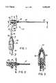
- FIG. 1is a perspective view of the needle system of the present invention.
- FIG. 2is a sectional view of the hub portion of the FIG. 1 needle system taken along line 2--2 of FIG. 1.
- FIG. 3is a sectional view of the reservoir of the FIG. 1 needle system showing the tube entering therein.
- Needle assembly 10generally denotes the needle system of the present invention.
- Needle assembly 10includes an elongated needle 12 having a distal end 14 and a proximal end 16. Distal end 14 is shaped and dimensioned for introduction into the vascular system.
- Elongated needle 12has a predetermined volume.
- a needle hub 18is situated at the proximal end 16 of the needle 12. The needle hub 18 has a predetermined volume.
- a port 20is positioned between the proximal end of the needle hub and the proximal needle end.
- a visualization connector tube 22is provided.
- Connector tube 22has a first end 24 and a second end 26.
- First end 24 of tube 22is in communication with port 20.
- Tube 22has a predetermined volume.
- Tube 22is sufficiently clear to permit visualization of material therein and, in the preferred embodiment of the invention the tube is formed of a clear polyvinyl chloride.
- An elastomeric reservoir 28is provided. Reservoir 28 in free, direct, unrestricted two-way communication with the second end 26 of the tube 22. Elastomeric reservoir 28 has an initial unexpanded state in which it has a first pressure and a first volume. Elastomeric reservoir 28 has a second expanded state in which it has a second pressure and a second volume.
- reservoir 28is tapered in shape. When injections are made through reservoir 28 the taper minimizes turbulence.
- the first pressure of the reservoiris approximately equal to ambient air pressure
- the second pressure of the reservoircorrelates to human blood pressure
- Needle system 10includes a gasket 27 which in the preferred embodiment is a slit, silicone diaphragm disk.
- a guidewire(not shown) can be passed into the gasket and into needle 12. The guidewire is passed through an opening 18a in the hub.
- the gasketprovides a barrier to the flow of blood. Thus, blood which enters the needle, under pressure, cannot exit from the hub.
- a syringe valve 30 or stopcock, or other appropriate mechanismis provided proximal to the reservoir.
- tube 22has markings 34 which indicate approximate blood pressure.
- the first marking 34a on tube 22is about 0.20 inches from the point the tube 22 connects to the hub 18. Subsequent markings are spaced from one another by 0.39 inches.
- the first marking 34acorresponds to a pressure of about 40 mm Hg and the distance between each marking corresponds to about 20 mm Hg.
- Needle 12has an internal diameter of between 0,018 and 0.075 inches, a length of between 0.5 and 6.0 inches, and a volume of between 0.000127 and 0.026507 cubic inches.
- the needle hub 18is formed with a volume of between 0.0005 and 0.003 cubic inches.
- Tube 22is formed with an internal diameter of between 0.020 and 0.100 inches, a length of between 2.0 and 8.0 inches and a volume of between 0.0006 and 0.063 cubic inches.
- Reservoir 28is formed with a volume of between 0.010 and 0.060 cubic inches.
- the needle 12has an internal diameter of about 0.042 inches, a length of about 3.0 inches and a volume of about 0.0042 cubic inches.
- the hubhas a volume of about 0.001 cubic inches.
- tube 22has an internal diameter of about 0.070 inches, a length of about 5.0 inches and a volume of about 0.019 inches.
- the reservoir in its first statehas a volume of about 0.025 cubic inches (at ambient pressure) and its second state a volume of about 0.040 cubic inches at a pressure of 300 mmHg (5.77 psi).
- needle system 10works as follows. When elongated needle 12 is placed in an artery, the arterial blood which is under pressure, displaces and compresses the air that is contained in needle 12, hub 18, and a portion of the tube 22. The displaced, compressed air migrates into reservoir 28 causing reservoir 28 to expand to its expanded state. As the air pressure in the elastomeric reservoir 28 equals the blood pressure, continuous visualization of pulsatile blood flow can be seen in tube 22. The actual distance that blood travels up tube 22 can be varied by varying the internal dimensions or material compositions of the various components of the system and thereby the volume of available compressible air.
- syringe activated valve 30When needle 12 is placed in an artery, syringe activated valve 30 is positioned to insure that the system is closed. In lieu of a syringe activated valve a stopcock can be used.
- V1the volume of the needle system which includes the needle, hub, visualization connector tube and the initial unexpanded volume of the elastomeric reservoir
- V2the original volume of the unexpanded elastomeric reservoir plus the volume of the expanded portion of the elastomeric reservoir plus a chosen percentage of the connector tube left unfilled with blood
- P1the ambient air pressure (i.e. 14.7 psi at standard conditions)
- V1The closed system initial volume, V1, can be expressed as;
- Vnthe volume of the needle
- Vhthe volume of the needle hub
- Vtthe volume of the visualization connector tube
- Vrthe initial unexpanded volume of the elastomeric reservoir.
- the second volume of air, V2is equal to the original unexpanded reservoir volume (Vr) plus the expanded volume of the elastomeric reservoir at P2 ( ⁇ Vr) plus a chosen percentage (L) of the pulsatile visualization connector tube left unfilled with blood.
- the change in the volume of the elastomeric reservoir ⁇ Vris a function of the pressure P2, as P2 increases, the volumetric expansion ⁇ Vr increases.
- the air contained in the needle, needle hub and a portion of the visualization connector tubemust be displaced or compressed into the remaining portions of the closed needle system.
- the desired percentage (L) of the visualization connector tube remaining filled with air or unfilled with blood at P2can be determined by,
- the percentage of the connector tube filled with blood (Lf) at any given set of conditionscan be determined by,
- P2is determined by the arterial blood pressure which continually pulsates from the systolic to the diastolic blood pressure.
- the percentage of the connector tube filled with blood pulsatesaccording to equation (1.7). This effect allows the user to visually verify needle placement using the closed needle system.
- the shape, length and volume of the visualization connector tubeare dimensioned to allow visualization of the arterial pulse over the full range of blood pressures.
- elastomeric reservoir 28may be housed in a rigid protective enclosure 36 to prevent accidental squeezing or manipulation of the elastomeric reservoir 28.
- Rigid housing 36further controls and limits the expansion of the flexible reservoir 28 to allow test injections and road mapping for needle placement verification.
- reservoir 28is made of polyvinyl chloride
- hub 18is made of polycarbonate
- the needle 12is made of stainless steel.
Landscapes
- Health & Medical Sciences (AREA)
- Life Sciences & Earth Sciences (AREA)
- Biophysics (AREA)
- Pulmonology (AREA)
- Engineering & Computer Science (AREA)
- Anesthesiology (AREA)
- Biomedical Technology (AREA)
- Heart & Thoracic Surgery (AREA)
- Hematology (AREA)
- Animal Behavior & Ethology (AREA)
- General Health & Medical Sciences (AREA)
- Public Health (AREA)
- Veterinary Medicine (AREA)
- Infusion, Injection, And Reservoir Apparatuses (AREA)
Abstract
Description
V.sub.2 /V.sub.1 =(P.sub.1 /P.sub.2).sup.0.71 (1.1)
V1=Vn+Vh+Vt+Vr (1.2)(1.2)
V2=Vr+ΔVr+L(Vt) (1.3)
V.sub.2 =(P.sub.1 /P.sub.2).sup.0.71 (V1) (1.4)
Vr+ΔVr+L(Vt)=(P.sub.1 /P.sub.2).sup.0.71 (V1) (1.5)
L=((P1/P2).sup.0.71 (V1)-(Vr+ΔVr))/Vt (1.6)
Lf=1-((P1/P2).sup.0.71 (V1)-(Vr+ΔVr))/Vt (1.7)
Claims (13)
Priority Applications (1)
| Application Number | Priority Date | Filing Date | Title |
|---|---|---|---|
| US08/231,276US5439449A (en) | 1994-04-22 | 1994-04-22 | Flow visualization needle system |
Applications Claiming Priority (1)
| Application Number | Priority Date | Filing Date | Title |
|---|---|---|---|
| US08/231,276US5439449A (en) | 1994-04-22 | 1994-04-22 | Flow visualization needle system |
Publications (1)
| Publication Number | Publication Date |
|---|---|
| US5439449Atrue US5439449A (en) | 1995-08-08 |
Family
ID=22868515
Family Applications (1)
| Application Number | Title | Priority Date | Filing Date |
|---|---|---|---|
| US08/231,276Expired - Fee RelatedUS5439449A (en) | 1994-04-22 | 1994-04-22 | Flow visualization needle system |
Country Status (1)
| Country | Link |
|---|---|
| US (1) | US5439449A (en) |
Cited By (54)
| Publication number | Priority date | Publication date | Assignee | Title |
|---|---|---|---|---|
| US5792044A (en)* | 1996-03-22 | 1998-08-11 | Danek Medical, Inc. | Devices and methods for percutaneous surgery |
| US5820596A (en)* | 1993-11-02 | 1998-10-13 | Merit Medical Systems | Vascular blood containment device |
| US5876384A (en)* | 1995-10-05 | 1999-03-02 | Dragan; William B. | Micro aspirator |
| FR2782627A1 (en)* | 1998-09-01 | 2000-03-03 | Vygon | ARTERIAL PUNCTURE NEEDLE |
| US6152871A (en)* | 1996-03-22 | 2000-11-28 | Sdgi Holdings, Inc. | Apparatus for percutaneous surgery |
| US6162170A (en)* | 1996-03-22 | 2000-12-19 | Sdgi Holdings, Inc. | Devices and methods for percutaneous surgery |
| US6514260B1 (en) | 2000-03-15 | 2003-02-04 | Sdgi Holdings, Inc. | Methods and instruments for laparoscopic spinal surgery |
| US6679833B2 (en) | 1996-03-22 | 2004-01-20 | Sdgi Holdings, Inc. | Devices and methods for percutaneous surgery |
| US20040176763A1 (en)* | 1996-03-22 | 2004-09-09 | Foley Kevin T. | Methods for percutaneous surgery |
| US20040186346A1 (en)* | 1996-03-22 | 2004-09-23 | Smith Maurice M. | Devices and methods for percutaneous surgery |
| US20050257612A1 (en)* | 2004-05-21 | 2005-11-24 | Todd Hiemer | Aspirator systems having an aspirator tip optical level detector and methods for using the same |
| US7056321B2 (en) | 2000-08-01 | 2006-06-06 | Endius, Incorporated | Method of securing vertebrae |
| US20060241350A1 (en)* | 2005-04-22 | 2006-10-26 | Sdgi Holdings, Inc. | Instruments and methods for selective tissue retraction through a retractor sleeve |
| US20080319346A1 (en)* | 2007-03-07 | 2008-12-25 | Becton, Dickinson And Company | Safety Blood Collection Assembly With Indicator |
| US20090204026A1 (en)* | 2007-03-07 | 2009-08-13 | Becton, Dickinson And Company | Safety Blood Collection Assembly With Indicator |
| US20090227896A1 (en)* | 2008-03-07 | 2009-09-10 | Becton, Dickinson And Company | Flashback Blood Collection Needle |
| US20090227953A1 (en)* | 2008-03-07 | 2009-09-10 | Becton, Dickinson And Company | Flashback Blood Collection Needle |
| US20110178427A1 (en)* | 2008-03-07 | 2011-07-21 | Becton, Dickinson And Company | Flashback Blood Collection Needle |
| US7985247B2 (en) | 2000-08-01 | 2011-07-26 | Zimmer Spine, Inc. | Methods and apparatuses for treating the spine through an access device |
| US8287498B2 (en) | 2002-06-11 | 2012-10-16 | Bd Medical Products, Pte. Ltd. | Flashback blood collection needle with needle shield |
| US8540746B2 (en) | 1998-08-20 | 2013-09-24 | Zimmer Spine, Inc. | Cannula for receiving surgical instruments |
| US11020571B2 (en) | 2005-07-06 | 2021-06-01 | Vascular Pathways, Inc. | Intravenous catheter insertion device and method of use |
| USD921884S1 (en) | 2018-07-27 | 2021-06-08 | Bard Access Systems, Inc. | Catheter insertion device |
| US11033719B2 (en) | 2014-09-05 | 2021-06-15 | C. R. Bard, Inc. | Catheter insertion device including retractable needle |
| US11123524B2 (en) | 2011-02-25 | 2021-09-21 | C. R. Bard, Inc. | Medical component insertion device including a retractable needle |
| US11135406B2 (en) | 2010-05-14 | 2021-10-05 | C. R. Bard, Inc. | Catheter insertion device including top-mounted advancement components |
| US20210330942A1 (en)* | 2020-04-27 | 2021-10-28 | Bard Access Systems, Inc. | Rapidly Insertable Central Catheters Including Catheter Assemblies and Methods Thereof |
| US11202886B2 (en) | 2011-01-31 | 2021-12-21 | Vascular Pathways, Inc. | Intravenous catheter and insertion device with reduced blood spatter |
| WO2022005892A3 (en)* | 2020-06-29 | 2022-02-17 | Bard Access Systems, Inc. | Rapidly insertable central catheters including catheter assemblies and methods thereof |
| US11278702B2 (en) | 2010-05-14 | 2022-03-22 | C. R. Bard, Inc. | Guidewire extension system for a catheter placement device |
| US11389626B2 (en) | 2018-03-07 | 2022-07-19 | Bard Access Systems, Inc. | Guidewire advancement and blood flashback systems for a medical device insertion system |
| US11400260B2 (en) | 2017-03-01 | 2022-08-02 | C. R. Bard, Inc. | Catheter insertion device |
| US11517719B2 (en) | 2019-09-24 | 2022-12-06 | Bard Access Systems, Inc. | Integrated acute central venous catheter and peripherally inserted venous catheter |
| US11559665B2 (en) | 2019-08-19 | 2023-01-24 | Becton, Dickinson And Company | Midline catheter placement device |
| US11759618B2 (en) | 2016-09-12 | 2023-09-19 | C. R. Bard, Inc. | Blood control for a catheter insertion device |
| US11819638B2 (en) | 2020-05-21 | 2023-11-21 | Bard Access Systems, Inc. | Rapidly insertable central catheters including catheter assemblies and methods thereof |
| US11826526B2 (en) | 2020-01-23 | 2023-11-28 | Bard Access Systems, Inc. | Splitable catheter docking station system and method |
| US11890429B2 (en) | 2019-09-10 | 2024-02-06 | Bard Access Systems, Inc. | Rapidly inserted central catheter and methods thereof |
| US11918767B2 (en) | 2020-04-23 | 2024-03-05 | Bard Access Systems, Inc. | Rapidly insertable central catheters including catheter assemblies and methods thereof |
| US11925779B2 (en) | 2010-05-14 | 2024-03-12 | C. R. Bard, Inc. | Catheter insertion device including top-mounted advancement components |
| US12064576B2 (en) | 2020-03-13 | 2024-08-20 | Bard Access Systems, Inc. | Guidewire-management devices and methods thereof |
| US12097342B2 (en) | 2015-01-29 | 2024-09-24 | Becton, Dickinson And Company | Rapid insertion integrated catheter and method of using an integrated catheter |
| US12138405B2 (en) | 2020-12-17 | 2024-11-12 | Bard Access Systems, Inc. | Rapidly insertable central catheters, assemblies, and methods thereof |
| US12161819B2 (en) | 2015-05-15 | 2024-12-10 | C. R. Bard, Inc. | Catheter placement device including an extensible needle safety component |
| US12186494B2 (en) | 2020-03-13 | 2025-01-07 | Bard Access Systems, Inc. | Guidewire-management devices and methods thereof |
| US12186503B2 (en) | 2019-10-25 | 2025-01-07 | Bard Access Systems, Inc. | Guidewire-management devices and methods thereof |
| US12246149B2 (en) | 2019-04-12 | 2025-03-11 | Teleflex Medical Incorporated | Catheter insertion apparatus with continuous visible flashback |
| US12263316B2 (en) | 2020-12-21 | 2025-04-01 | Bard Access Systems, Inc. | Fluid path optimization in catheter insertion systems |
| USD1069106S1 (en) | 2015-05-01 | 2025-04-01 | C. R. Bard, Inc. | Catheter placement device |
| US12274836B2 (en) | 2020-06-29 | 2025-04-15 | Bard Access Systems, Inc. | Rapidly insertable central catheters including assemblies and methods thereof |
| US12290644B2 (en) | 2020-10-28 | 2025-05-06 | Bard Access Systems, Inc. | Catheter placement system with stiffening system |
| US12296115B2 (en) | 2010-05-14 | 2025-05-13 | C. R. Bard, Inc. | Insertion device |
| US12357794B2 (en) | 2020-12-21 | 2025-07-15 | Bard Access Systems, Inc. | Optimized structural support in catheter insertion systems |
| US12440652B2 (en) | 2019-09-20 | 2025-10-14 | Bard Peripheral Vascular, Inc. | Intravenous catheter-placement device and method thereof |
Citations (4)
| Publication number | Priority date | Publication date | Assignee | Title |
|---|---|---|---|---|
| US4655750A (en)* | 1985-11-22 | 1987-04-07 | Manresa, Inc. | Closed system catheter with guide wire |
| US5092845A (en)* | 1989-07-10 | 1992-03-03 | Critikon, Inc. | Catheter with needle gasket |
| US5122121A (en)* | 1990-08-30 | 1992-06-16 | E-Z-Em, Inc. | Safety needle assembly |
| US5306254A (en)* | 1992-10-01 | 1994-04-26 | Kensey Nash Corporation | Vessel position locating device and method of use |
- 1994
- 1994-04-22USUS08/231,276patent/US5439449A/ennot_activeExpired - Fee Related
Patent Citations (4)
| Publication number | Priority date | Publication date | Assignee | Title |
|---|---|---|---|---|
| US4655750A (en)* | 1985-11-22 | 1987-04-07 | Manresa, Inc. | Closed system catheter with guide wire |
| US5092845A (en)* | 1989-07-10 | 1992-03-03 | Critikon, Inc. | Catheter with needle gasket |
| US5122121A (en)* | 1990-08-30 | 1992-06-16 | E-Z-Em, Inc. | Safety needle assembly |
| US5306254A (en)* | 1992-10-01 | 1994-04-26 | Kensey Nash Corporation | Vessel position locating device and method of use |
Cited By (107)
| Publication number | Priority date | Publication date | Assignee | Title |
|---|---|---|---|---|
| US5820596A (en)* | 1993-11-02 | 1998-10-13 | Merit Medical Systems | Vascular blood containment device |
| US5876384A (en)* | 1995-10-05 | 1999-03-02 | Dragan; William B. | Micro aspirator |
| US20030139648A1 (en)* | 1996-03-22 | 2003-07-24 | Foley Kevin Thomas | Devices and methods for percutaneous surgery |
| US20040186346A1 (en)* | 1996-03-22 | 2004-09-23 | Smith Maurice M. | Devices and methods for percutaneous surgery |
| US5954635A (en)* | 1996-03-22 | 1999-09-21 | Sdgi Holdings Inc. | Devices and methods for percutaneous surgery |
| US6007487A (en)* | 1996-03-22 | 1999-12-28 | Sdgi Holdings, Inc. | Tissue retractor for use through a cannula |
| US7993378B2 (en) | 1996-03-22 | 2011-08-09 | Warsaw Orthopedic, IN. | Methods for percutaneous spinal surgery |
| US20070156020A1 (en)* | 1996-03-22 | 2007-07-05 | Foley Kevin T | Methods for percutaneous spinal surgery |
| US6152871A (en)* | 1996-03-22 | 2000-11-28 | Sdgi Holdings, Inc. | Apparatus for percutaneous surgery |
| US6162170A (en)* | 1996-03-22 | 2000-12-19 | Sdgi Holdings, Inc. | Devices and methods for percutaneous surgery |
| US6176823B1 (en) | 1996-03-22 | 2001-01-23 | Sdgi Holdings, Inc. | Fixture for supporting a viewing element within a cannula |
| US6206822B1 (en) | 1996-03-22 | 2001-03-27 | Sdgi Holdings, Inc. | Devices and methods for percutaneous surgery |
| US6217509B1 (en) | 1996-03-22 | 2001-04-17 | Sdgi Holdings, Inc. | Devices and methods for percutaneous surgery |
| US7198598B2 (en) | 1996-03-22 | 2007-04-03 | Warsaw Orthopedic, Inc. | Devices and methods for percutaneous surgery |
| US6425859B1 (en) | 1996-03-22 | 2002-07-30 | Sdgi Holdings, Inc. | Cannula and a retractor for percutaneous surgery |
| US20040176763A1 (en)* | 1996-03-22 | 2004-09-09 | Foley Kevin T. | Methods for percutaneous surgery |
| US6520907B1 (en) | 1996-03-22 | 2003-02-18 | Sdgi Holdings, Inc. | Methods for accessing the spinal column |
| US5902231A (en)* | 1996-03-22 | 1999-05-11 | Sdgi Holdings, Inc. | Devices and methods for percutaneous surgery |
| US5792044A (en)* | 1996-03-22 | 1998-08-11 | Danek Medical, Inc. | Devices and methods for percutaneous surgery |
| US6679833B2 (en) | 1996-03-22 | 2004-01-20 | Sdgi Holdings, Inc. | Devices and methods for percutaneous surgery |
| US8540746B2 (en) | 1998-08-20 | 2013-09-24 | Zimmer Spine, Inc. | Cannula for receiving surgical instruments |
| US6261263B1 (en)* | 1998-09-01 | 2001-07-17 | Vygon | Hub of arterial puncture needle |
| FR2782627A1 (en)* | 1998-09-01 | 2000-03-03 | Vygon | ARTERIAL PUNCTURE NEEDLE |
| EP0983774A1 (en)* | 1998-09-01 | 2000-03-08 | Vygon | Mounting of a needle for artery tapping |
| US20030083666A1 (en)* | 2000-03-15 | 2003-05-01 | Thomas Zdeblick | Methods and instruments for laparoscopic spinal surgery |
| US7179263B2 (en) | 2000-03-15 | 2007-02-20 | Sdgi Holdings, Inc. | Methods and instruments for laparoscopic spinal surgery |
| US6514260B1 (en) | 2000-03-15 | 2003-02-04 | Sdgi Holdings, Inc. | Methods and instruments for laparoscopic spinal surgery |
| US9101353B2 (en) | 2000-08-01 | 2015-08-11 | Zimmer Spine, Inc. | Method of securing vertebrae |
| US8777997B2 (en) | 2000-08-01 | 2014-07-15 | Zimmer Spine, Inc. | Method for securing vertebrae |
| US7056321B2 (en) | 2000-08-01 | 2006-06-06 | Endius, Incorporated | Method of securing vertebrae |
| US8277486B2 (en) | 2000-08-01 | 2012-10-02 | Zimmer Spine, Inc. | System for performing a procedure at a spinal location |
| US8864785B2 (en) | 2000-08-01 | 2014-10-21 | Zimmer Spine, Inc. | Method for securing vertebrae |
| US7850695B2 (en) | 2000-08-01 | 2010-12-14 | Zimmer Spine, Inc. | Method of securing vertebrae |
| US7985247B2 (en) | 2000-08-01 | 2011-07-26 | Zimmer Spine, Inc. | Methods and apparatuses for treating the spine through an access device |
| US7699877B2 (en) | 2000-08-01 | 2010-04-20 | Zimmer Spine, Inc. | Method of securing vertebrae |
| US7722530B2 (en) | 2000-08-01 | 2010-05-25 | Zimmer Spine, Inc. | Method of securing vertebrae |
| US9622735B2 (en) | 2000-08-01 | 2017-04-18 | Zimmer Spine, Inc. | Method for securing vertebrae |
| US8708964B2 (en) | 2002-06-11 | 2014-04-29 | Bd Medical Products, Pte. Ltd. | Flashback blood collection needle with needle shield |
| US8287498B2 (en) | 2002-06-11 | 2012-10-16 | Bd Medical Products, Pte. Ltd. | Flashback blood collection needle with needle shield |
| US20050257612A1 (en)* | 2004-05-21 | 2005-11-24 | Todd Hiemer | Aspirator systems having an aspirator tip optical level detector and methods for using the same |
| US7537735B2 (en) | 2004-05-21 | 2009-05-26 | Biomerieux, Inc. | Aspirator systems having an aspirator tip optical level detector and methods for using the same |
| US7427264B2 (en) | 2005-04-22 | 2008-09-23 | Warsaw Orthopedic, Inc. | Instruments and methods for selective tissue retraction through a retractor sleeve |
| US20060241350A1 (en)* | 2005-04-22 | 2006-10-26 | Sdgi Holdings, Inc. | Instruments and methods for selective tissue retraction through a retractor sleeve |
| US11020571B2 (en) | 2005-07-06 | 2021-06-01 | Vascular Pathways, Inc. | Intravenous catheter insertion device and method of use |
| US11577054B2 (en) | 2005-07-06 | 2023-02-14 | Vascular Pathways, Inc. | Intravenous catheter insertion device and method of use |
| US11925778B2 (en) | 2005-07-06 | 2024-03-12 | Vascular Pathways, Inc. | Intravenous catheter insertion device |
| US12370349B2 (en) | 2005-07-06 | 2025-07-29 | Vascular Pathways, Inc. | Intravenous catheter insertion device and method of use |
| US8888713B2 (en) | 2007-03-07 | 2014-11-18 | Becton, Dickinson And Company | Safety blood collection assembly with indicator |
| US9687184B2 (en) | 2007-03-07 | 2017-06-27 | Becton, Dickinson And Company | Safety blood collection assembly with indicator |
| US20090204026A1 (en)* | 2007-03-07 | 2009-08-13 | Becton, Dickinson And Company | Safety Blood Collection Assembly With Indicator |
| US20080319346A1 (en)* | 2007-03-07 | 2008-12-25 | Becton, Dickinson And Company | Safety Blood Collection Assembly With Indicator |
| US11020033B2 (en) | 2007-03-07 | 2021-06-01 | Becton, Dickinson And Company | Safety blood collection assembly with indicator |
| US10588558B2 (en) | 2007-03-07 | 2020-03-17 | Becton, Dickinson And Company | Safety blood collection assembly with indicator |
| US9095288B2 (en) | 2007-03-07 | 2015-08-04 | Becton, Dickinson And Company | Safety blood collection assembly with indicator |
| US10349880B2 (en) | 2007-03-07 | 2019-07-16 | Becton, Dickinson And Company | Safety blood collection assembly with indicator |
| US10085680B2 (en) | 2007-03-07 | 2018-10-02 | Becton, Dickinson And Company | Safety blood collection assembly with indicator |
| US9271668B2 (en) | 2007-03-07 | 2016-03-01 | Becton, Dickinson And Company | Safety blood collection assembly with indicator |
| US9615783B2 (en) | 2007-03-07 | 2017-04-11 | Becton, Dickinson And Company | Safety blood collection assembly with indicator |
| US20090227896A1 (en)* | 2008-03-07 | 2009-09-10 | Becton, Dickinson And Company | Flashback Blood Collection Needle |
| US8795198B2 (en) | 2008-03-07 | 2014-08-05 | Becton, Dickinson And Company | Flashback blood collection needle |
| US9167996B2 (en) | 2008-03-07 | 2015-10-27 | Becton, Dickinson And Company | Flashback blood collection needle |
| US20100262038A1 (en)* | 2008-03-07 | 2010-10-14 | Becton, Dickinson And Company | Flashback Blood Collection Needle |
| US20110178427A1 (en)* | 2008-03-07 | 2011-07-21 | Becton, Dickinson And Company | Flashback Blood Collection Needle |
| US8282605B2 (en) | 2008-03-07 | 2012-10-09 | Becton, Dickinson And Company | Flashback blood collection needle |
| US20090227953A1 (en)* | 2008-03-07 | 2009-09-10 | Becton, Dickinson And Company | Flashback Blood Collection Needle |
| US8585653B2 (en) | 2008-03-07 | 2013-11-19 | Becton, Dickinson And Company | Flashback blood collection needle |
| US7766879B2 (en)* | 2008-03-07 | 2010-08-03 | Becton, Dickinson And Company | Flashback blood collection needle |
| US8603009B2 (en) | 2008-03-07 | 2013-12-10 | Becton, Dickinson And Company | Flashback blood collection needle |
| US11135406B2 (en) | 2010-05-14 | 2021-10-05 | C. R. Bard, Inc. | Catheter insertion device including top-mounted advancement components |
| US11925779B2 (en) | 2010-05-14 | 2024-03-12 | C. R. Bard, Inc. | Catheter insertion device including top-mounted advancement components |
| US11278702B2 (en) | 2010-05-14 | 2022-03-22 | C. R. Bard, Inc. | Guidewire extension system for a catheter placement device |
| US12296115B2 (en) | 2010-05-14 | 2025-05-13 | C. R. Bard, Inc. | Insertion device |
| US11202886B2 (en) | 2011-01-31 | 2021-12-21 | Vascular Pathways, Inc. | Intravenous catheter and insertion device with reduced blood spatter |
| US11123524B2 (en) | 2011-02-25 | 2021-09-21 | C. R. Bard, Inc. | Medical component insertion device including a retractable needle |
| US11931534B2 (en) | 2011-02-25 | 2024-03-19 | C. R. Bard, Inc. | Medical component insertion device including a retractable needle |
| US11033719B2 (en) | 2014-09-05 | 2021-06-15 | C. R. Bard, Inc. | Catheter insertion device including retractable needle |
| US11565089B2 (en) | 2014-09-05 | 2023-01-31 | C. R. Bard, Inc. | Catheter insertion device including retractable needle |
| US12097342B2 (en) | 2015-01-29 | 2024-09-24 | Becton, Dickinson And Company | Rapid insertion integrated catheter and method of using an integrated catheter |
| USD1069106S1 (en) | 2015-05-01 | 2025-04-01 | C. R. Bard, Inc. | Catheter placement device |
| US12161819B2 (en) | 2015-05-15 | 2024-12-10 | C. R. Bard, Inc. | Catheter placement device including an extensible needle safety component |
| US11759618B2 (en) | 2016-09-12 | 2023-09-19 | C. R. Bard, Inc. | Blood control for a catheter insertion device |
| US12403294B2 (en) | 2016-09-12 | 2025-09-02 | C. R. Bard, Inc. | Blood control for a catheter insertion device |
| US12357796B2 (en) | 2017-03-01 | 2025-07-15 | C. R. Bard, Inc. | Catheter insertion device |
| US11400260B2 (en) | 2017-03-01 | 2022-08-02 | C. R. Bard, Inc. | Catheter insertion device |
| US12017020B2 (en) | 2018-03-07 | 2024-06-25 | Bard Access Systems, Inc. | Guidewire advancement and blood flashback systems for a medical device insertion system |
| US11389626B2 (en) | 2018-03-07 | 2022-07-19 | Bard Access Systems, Inc. | Guidewire advancement and blood flashback systems for a medical device insertion system |
| USD921884S1 (en) | 2018-07-27 | 2021-06-08 | Bard Access Systems, Inc. | Catheter insertion device |
| US12246149B2 (en) | 2019-04-12 | 2025-03-11 | Teleflex Medical Incorporated | Catheter insertion apparatus with continuous visible flashback |
| US11559665B2 (en) | 2019-08-19 | 2023-01-24 | Becton, Dickinson And Company | Midline catheter placement device |
| US11883615B2 (en) | 2019-08-19 | 2024-01-30 | Becton, Dickinson And Company | Midline catheter placement device |
| US11890429B2 (en) | 2019-09-10 | 2024-02-06 | Bard Access Systems, Inc. | Rapidly inserted central catheter and methods thereof |
| US12440652B2 (en) | 2019-09-20 | 2025-10-14 | Bard Peripheral Vascular, Inc. | Intravenous catheter-placement device and method thereof |
| US11517719B2 (en) | 2019-09-24 | 2022-12-06 | Bard Access Systems, Inc. | Integrated acute central venous catheter and peripherally inserted venous catheter |
| US12186503B2 (en) | 2019-10-25 | 2025-01-07 | Bard Access Systems, Inc. | Guidewire-management devices and methods thereof |
| US11826526B2 (en) | 2020-01-23 | 2023-11-28 | Bard Access Systems, Inc. | Splitable catheter docking station system and method |
| US12064576B2 (en) | 2020-03-13 | 2024-08-20 | Bard Access Systems, Inc. | Guidewire-management devices and methods thereof |
| US12186494B2 (en) | 2020-03-13 | 2025-01-07 | Bard Access Systems, Inc. | Guidewire-management devices and methods thereof |
| US11918767B2 (en) | 2020-04-23 | 2024-03-05 | Bard Access Systems, Inc. | Rapidly insertable central catheters including catheter assemblies and methods thereof |
| US20210330942A1 (en)* | 2020-04-27 | 2021-10-28 | Bard Access Systems, Inc. | Rapidly Insertable Central Catheters Including Catheter Assemblies and Methods Thereof |
| US11819638B2 (en) | 2020-05-21 | 2023-11-21 | Bard Access Systems, Inc. | Rapidly insertable central catheters including catheter assemblies and methods thereof |
| US12274836B2 (en) | 2020-06-29 | 2025-04-15 | Bard Access Systems, Inc. | Rapidly insertable central catheters including assemblies and methods thereof |
| WO2022005892A3 (en)* | 2020-06-29 | 2022-02-17 | Bard Access Systems, Inc. | Rapidly insertable central catheters including catheter assemblies and methods thereof |
| US12161820B2 (en) | 2020-06-29 | 2024-12-10 | Bard Access Systems, Inc. | Rapidly insertable central catheters including catheter assemblies and methods thereof |
| US12290644B2 (en) | 2020-10-28 | 2025-05-06 | Bard Access Systems, Inc. | Catheter placement system with stiffening system |
| US12138405B2 (en) | 2020-12-17 | 2024-11-12 | Bard Access Systems, Inc. | Rapidly insertable central catheters, assemblies, and methods thereof |
| US12263316B2 (en) | 2020-12-21 | 2025-04-01 | Bard Access Systems, Inc. | Fluid path optimization in catheter insertion systems |
| US12357794B2 (en) | 2020-12-21 | 2025-07-15 | Bard Access Systems, Inc. | Optimized structural support in catheter insertion systems |
Similar Documents
| Publication | Publication Date | Title |
|---|---|---|
| US5439449A (en) | Flow visualization needle system | |
| US5071411A (en) | Pressure-actuated valve for sealing flow conduit | |
| US4267835A (en) | Medical flushing valve | |
| US4381591A (en) | Method of assembling medical flushing valve | |
| US5902273A (en) | Pressurizable epidural space identification syringe | |
| US3675891A (en) | Continuous catheter flushing apparatus | |
| US4403988A (en) | Syringe assembly | |
| US4192303A (en) | Flow regulating device for arterial catheter systems | |
| US5454374A (en) | Pressure-measuring method and needle system for hemodialysis | |
| US4946133A (en) | Hemostasis valve | |
| US4142525A (en) | Syringe assembly | |
| US4430081A (en) | Hemostasis sheath | |
| US4337769A (en) | Pressure infusion module | |
| US5980492A (en) | Vascular blood containment device | |
| US4000741A (en) | Syringe assembly | |
| US4741345A (en) | Continuous flow tissue pressure measurement | |
| US5395330A (en) | Auto-inflating catheter cuff | |
| US5738664A (en) | Self-healing seal for use in medical devices | |
| US4337770A (en) | Flow regulating device for arterial catheter systems | |
| US4739769A (en) | Tissue pressure measurement transducer system | |
| US4759751A (en) | Catheter assembly with air purging feature | |
| DE69621232T2 (en) | HYPERTHERMAL TREATMENT DEVICE | |
| US4267834A (en) | System for flushing a medical fluid | |
| US4030497A (en) | Syringe assembly | |
| US4240430A (en) | Syringe assembly |
Legal Events
| Date | Code | Title | Description |
|---|---|---|---|
| AS | Assignment | Owner name:E-Z-EM, INC., NEW YORK Free format text:ASSIGNMENT OF ASSIGNORS INTEREST;ASSIGNORS:MAPES, HAROLD C., JR.;APPLING, WILLIAM M.;CODY, MICHAEL P.;AND OTHERS;REEL/FRAME:006971/0574;SIGNING DATES FROM 19940411 TO 19940414 | |
| AS | Assignment | Owner name:ANGIODYNAMICS, INC., NEW YORK Free format text:ASSIGNMENT OF ASSIGNORS INTEREST;ASSIGNOR:E-Z-EM, INC.;REEL/FRAME:008401/0401 Effective date:19970226 | |
| REMI | Maintenance fee reminder mailed | ||
| LAPS | Lapse for failure to pay maintenance fees | ||
| FP | Expired due to failure to pay maintenance fee | Effective date:19990808 | |
| FPAY | Fee payment | Year of fee payment:8 | |
| AS | Assignment | Owner name:JPMORGAN CHASE BANK, N.A., AS ADMINISTRATIVE AGENT Free format text:SECURITY AGREEMENT;ASSIGNOR:ANGIODYNAMICS, INC.;REEL/FRAME:028260/0329 Effective date:20120522 | |
| AS | Assignment | Owner name:JPMORGAN CHASE BANK, N.A., AS ADMINISTRATIVE AGENT, ILLINOIS Free format text:SECURITY AGREEMENT;ASSIGNOR:ANGIODYNAMICS, INC.;REEL/FRAME:031315/0720 Effective date:20130919 Owner name:ANGIODYNAMICS, INC., NEW YORK Free format text:RELEASE BY SECURED PARTY;ASSIGNOR:JPMORGAN CHASE BANK N.A., AS ADMINISTRATIVE AGENT;REEL/FRAME:031315/0361 Effective date:20130919 Owner name:JPMORGAN CHASE BANK, N.A., AS ADMINISTRATIVE AGENT Free format text:SECURITY AGREEMENT;ASSIGNOR:ANGIODYNAMICS, INC.;REEL/FRAME:031315/0720 Effective date:20130919 | |
| AS | Assignment | Owner name:ANGIODYNAMICS, INC., NEW YORK Free format text:RELEASE BY SECURED PARTY;ASSIGNOR:JPMORGAN CHASE BANK, N.A., AS ADMINISTRATIVE AGENT;REEL/FRAME:040688/0540 Effective date:20161107 | |
| STCH | Information on status: patent discontinuation | Free format text:PATENT EXPIRED DUE TO NONPAYMENT OF MAINTENANCE FEES UNDER 37 CFR 1.362 |