US5439219A - Golf club shaft with optimized distribution of flexibility - Google Patents
Golf club shaft with optimized distribution of flexibilityDownload PDFInfo
- Publication number
- US5439219A US5439219AUS08/255,733US25573394AUS5439219AUS 5439219 AUS5439219 AUS 5439219AUS 25573394 AUS25573394 AUS 25573394AUS 5439219 AUS5439219 AUS 5439219A
- Authority
- US
- United States
- Prior art keywords
- shaft
- length
- golf club
- rigidity
- joined
- Prior art date
- Legal status (The legal status is an assumption and is not a legal conclusion. Google has not performed a legal analysis and makes no representation as to the accuracy of the status listed.)
- Expired - Fee Related
Links
- 239000000835fiberSubstances0.000claimsdescription25
- OKTJSMMVPCPJKN-UHFFFAOYSA-NCarbonChemical compound[C]OKTJSMMVPCPJKN-UHFFFAOYSA-N0.000claimsdescription11
- 239000002131composite materialSubstances0.000claimsdescription9
- 239000011521glassSubstances0.000claimsdescription5
- 241000531908AramidesSpecies0.000claimsdescription4
- 229920003235aromatic polyamidePolymers0.000claimsdescription4
- 229910002804graphiteInorganic materials0.000claimsdescription4
- 239000010439graphiteSubstances0.000claimsdescription4
- 230000003247decreasing effectEffects0.000claimsdescription3
- 230000007423decreaseEffects0.000description8
- 239000000463materialSubstances0.000description8
- 229910052799carbonInorganic materials0.000description7
- 230000008602contractionEffects0.000description7
- 230000000295complement effectEffects0.000description3
- 230000009467reductionEffects0.000description3
- 239000011347resinSubstances0.000description2
- 229920005989resinPolymers0.000description2
- 229920001169thermoplasticPolymers0.000description2
- 239000004416thermosoftening plasticSubstances0.000description2
- 239000004593EpoxySubstances0.000description1
- 230000006978adaptationEffects0.000description1
- 230000008859changeEffects0.000description1
- 238000002474experimental methodMethods0.000description1
- 238000000465mouldingMethods0.000description1
- 230000000750progressive effectEffects0.000description1
- 230000003068static effectEffects0.000description1
- 230000007704transitionEffects0.000description1
Images


Classifications
- A—HUMAN NECESSITIES
- A63—SPORTS; GAMES; AMUSEMENTS
- A63B—APPARATUS FOR PHYSICAL TRAINING, GYMNASTICS, SWIMMING, CLIMBING, OR FENCING; BALL GAMES; TRAINING EQUIPMENT
- A63B60/00—Details or accessories of golf clubs, bats, rackets or the like
- A—HUMAN NECESSITIES
- A63—SPORTS; GAMES; AMUSEMENTS
- A63B—APPARATUS FOR PHYSICAL TRAINING, GYMNASTICS, SWIMMING, CLIMBING, OR FENCING; BALL GAMES; TRAINING EQUIPMENT
- A63B53/00—Golf clubs
- A63B53/10—Non-metallic shafts
- A—HUMAN NECESSITIES
- A63—SPORTS; GAMES; AMUSEMENTS
- A63B—APPARATUS FOR PHYSICAL TRAINING, GYMNASTICS, SWIMMING, CLIMBING, OR FENCING; BALL GAMES; TRAINING EQUIPMENT
- A63B60/00—Details or accessories of golf clubs, bats, rackets or the like
- A63B60/0081—Substantially flexible shafts; Hinged shafts
- A—HUMAN NECESSITIES
- A63—SPORTS; GAMES; AMUSEMENTS
- A63B—APPARATUS FOR PHYSICAL TRAINING, GYMNASTICS, SWIMMING, CLIMBING, OR FENCING; BALL GAMES; TRAINING EQUIPMENT
- A63B60/00—Details or accessories of golf clubs, bats, rackets or the like
- A63B60/06—Handles
- A—HUMAN NECESSITIES
- A63—SPORTS; GAMES; AMUSEMENTS
- A63B—APPARATUS FOR PHYSICAL TRAINING, GYMNASTICS, SWIMMING, CLIMBING, OR FENCING; BALL GAMES; TRAINING EQUIPMENT
- A63B60/00—Details or accessories of golf clubs, bats, rackets or the like
- A63B60/06—Handles
- A63B60/08—Handles characterised by the material
- A—HUMAN NECESSITIES
- A63—SPORTS; GAMES; AMUSEMENTS
- A63B—APPARATUS FOR PHYSICAL TRAINING, GYMNASTICS, SWIMMING, CLIMBING, OR FENCING; BALL GAMES; TRAINING EQUIPMENT
- A63B60/00—Details or accessories of golf clubs, bats, rackets or the like
- A63B60/06—Handles
- A63B60/10—Handles with means for indicating correct holding positions
- Y—GENERAL TAGGING OF NEW TECHNOLOGICAL DEVELOPMENTS; GENERAL TAGGING OF CROSS-SECTIONAL TECHNOLOGIES SPANNING OVER SEVERAL SECTIONS OF THE IPC; TECHNICAL SUBJECTS COVERED BY FORMER USPC CROSS-REFERENCE ART COLLECTIONS [XRACs] AND DIGESTS
- Y10—TECHNICAL SUBJECTS COVERED BY FORMER USPC
- Y10S—TECHNICAL SUBJECTS COVERED BY FORMER USPC CROSS-REFERENCE ART COLLECTIONS [XRACs] AND DIGESTS
- Y10S273/00—Amusement devices: games
- Y10S273/23—High modulus filaments
Definitions
- the object of the present inventionis an improved golf club shaft and it is related more specifically to a shaft of a composite material whose flexibility distribution has been optimized in order to better the performance of the club.
- the inventionis also related to a golf club equipped with such a shaft.
- Prior art club shaftsare generally shaped like a truncated tubular section whose biggest diameter is found at the upper end (generally called the "butt"), adapted to receive the grip of the club and the smallest diameter is located at the lower end (called the “tip”), adapted to receive the club head.
- the rigidity values (EI) at the "butt" end of the shaftvary depending on the commercial availability of a shaft, from 60 to 100 N ⁇ m 2 (Newton ⁇ meters 2 ), but the rate of the curve remains substantially the same.
- back spinspeed of rotation
- angle at which the ball leaves with such so-called “flexible” shaftsare greater than with other shafts.
- the flight paths of the ballsare therefore higher and the ball stops more quickly upon striking the ground; this means that in terms of distance, the results are no greater than those achieved with conventional shafts having standard rigidity (curve C1). Rectification by decreasing the surface angle (called “static” loft) is not enough to adequately modify the values of these two parameters in order to improve club performance.
- U.S. Pat. No. 4,319,750discloses a shaft made of a composite material whose first 250 mm (millimeters) from the "butt" end are rendered more flexible with respect to the remainder of the shaft. This zone of reduced flexional rigidity corresponds to the gripping area of the club. The hands of the player surround or embed the club in this area, thereby resisting deformation in this area. Consequently, a greater flexibility in this area is hardly efficient, and the player is all the more disturbed because he has a tendency to fasten tightly onto the grip of the club in order to resist the deformation thus produced.
- An object of the present inventionis to optimize the distribution of the flexional rigidity of the shaft in accordance with its length so as to improve the general performance of the club, without disturbing the player, by displacing the flexibility outside of the hands of the player.
- the shaft as per the inventionis constituted of a tubular section having a flexional rigidity that evolves according to the length, comprising several portions:
- a rigid upper portion(at the "butt") extending from the upper end of the shaft with the greatest diameter, having a length (L1) at least equal to 100 mm, preferably 200 mm, and whose flexional rigidity is at least equal to 50 N ⁇ m 2 ;
- central portioncomprises a zone that is joined to the rigid upper portion, having a length (d) comprised between 100 and 300 mm and wherein flexional rigidity is comprised between 20 and 40 N ⁇ m 2 ; it being understood that L1+d ⁇ 500 mm; and,
- the flexible zoneis located in that portion of the shaft that is most biased during swing movement; in other words, just in front of the area corresponding to the embedding of the club by the hands of the player. The latter is rigid enough not to disturb the player. Beyond this flexible zone, the shaft portion is once again rigid so as to maintain a satisfactory rotational rate of the ball (back spin) and a satisfactory ball launching angle.
- the flexional rigidity of the upper portion of the golf club shaftis reduced in a direction from the upper end of the shaft towards the other end that is joined to the central portion.
- the inventorhas determined that the areas towards the "tip" end of the shaft influence the ball speed and rotation parameters only during time of contact with the ball. This portion, on the contrary, is hardly biased during swing movement, as opposed to the portion in the vicinity of the "butt" end. As such, it is advantageous to retain a minimal rigidity value, either constant or progressively variable towards the "tip" end so as to reduce the rotational speed of the ball.
- the lower portion whose length (L3) is comprised between 200 and 300 mmhas a flexional rigidity greater than or equal to 20 N ⁇ m 2 .
- the flexional rigidity of the lower portionincreases from the end that is joined to the central portion towards the lower end of the shaft.
- the flexional rigidity of the lower portionis substantially constant along the entire length (L3).
- the thickness of the tubular wall of the shaftcomprises a series of fiber-based composite material layers, such fibers being oriented in a direction parallel to the longitudinal axis of the shaft, and fiber based layers that are inclined with respect to the longitudinal axis of the shaft; the fibers that are oriented along a direction parallel to the longitudinal axis being for the most part fibers having a lower elastic modulus, in the flexible zone, than the elastic modulus of similarly oriented fibers outside of the flexible zone.
- the fibers oriented in a direction parallel to the longitudinal axis in the flexible zoneare, for the most part, made of glass and/or aramide.
- the fibers oriented along a direction parallel to the longitudinal axis outside the flexible zoneare, for the most part, made of graphite.
- the fibers that are inclined with respect to the axis of the shaftare, for the most part, made of graphite.
- FIG. 1represents a graph showing the distribution of flexional rigidity (EI), expressed by N ⁇ m 2 in the Y-axis; according to the length of shaft (L), expressed in millimeters in the X-axis, for a commercially available "rigid” shaft (C1) and a commercially available “flexible” shaft (C2).
- EIflexional rigidity
- FIG. 2represents a graph showing the influence exerted by the rigidity of a series of shafts having constant rigidity (in the X-axis) on the evolution of the speed of the ball (in the Y-axis on the right expressed in m/s and curve V) and on the evolution of the rate of rotation (in the Y-axis on the left in revolutions/minute and curve T).
- FIG. 3represents a graph illustrating an example, as per the invention, of the distribution of flexional rigidity (EI) according to the length (L) of the shaft (curve C).
- FIG. 4represents a graph showing the influence of the position of a flexible range 100 mm long in zone (d) as per the invention (indicated in the X-axis in mm) on the evolution of the rotational speed (indicated in the Y-axis on the left and curve T1) and on the evolution of ball speed (indicated in the Y-axis on the right and curve V1).
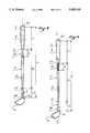
- FIG. 5shows an embodiment of a club according to the invention.
- FIG. 6shows a second embodiment of a club according to the invention.
- FIG. 7represents the evolution curve of the flexional rigidity (EI), in the Y-axis, according to length (L) of the shaft, in the X-axis for example I of an embodiment as per FIG. 5.
- FIG. 8represents the evolution curve of the flexional rigidity (EI), according to length (L) of the shaft for example II of an embodiment as per FIG. 6.
- the curve rate of the distribution of flexional rigidity (EI) according to lengthhas a shape that decreases substantially exponentially from the upper end of the shaft, called the "butt" end, towards the lower or “tip” end.
- Curve (C1)illustrates the case of a commercially available "rigid” shaft having a conventional truncated shape whose flexional rigidity at the "butt” end is greater than 90 N ⁇ m 2 . The decrease is due, in a large part, to the decrease in section or diameters in the direction of the "tip" end and whose formula is:
- Curve (C2)illustrates the case of a commercially available "flexible” shaft whose flexional rigidity at the "butt” is close to 60 N ⁇ m 2 .
- the rate of the curveis identical to that of (C1).
- FIG. 3illustrates an example as per the invention of the distribution of flexional rigidity in accordance with the length of the shaft.
- Shaft (1)can be broken down into several distinct portions.
- a rigid, upper portion (2)which extends from the "butt" end (20) and extends along a length (L1) at least equal to 200 mm, corresponding substantially to the length on which the hands of the player surround or embed the club.
- the rigidityshould be greater than or equal to 50N ⁇ m 2 , preferably greater than 70 N ⁇ m 2 , so as to ensure adequate rigidity for minimal deformation that does not disturb the player.
- the shaftcomprises a central portion (3) which is joined to the other end (21) of upper portion (2).
- This portionhas a length (L2) more or less substantial according to the type of shaft.
- This portion (3)is formed of a first zone (30) of length (d) that is especially flexible and is joined to end (21) of upper portion (2) on the one hand, and to the remaining zone (31) of central portion (3).
- This flexible zonehas a rigidity comprised between 20 and 40 N ⁇ m 2 and a length (d) comprised between 100 and 300 mm. However, it is important that the sum of (L1) and (d) be less or equal to 500 mm so that the shaft as per the invention may remain efficient.
- the graph of FIG. 4corresponds to a flexible zone having a length (d) equal to 100 mm on a normal shaft (rigidity towards the "butt" end of the shaft of 70N ⁇ m 2 , rigidity towards "tip” end of 30 N ⁇ m 2 on the last 300 mm, rigidity of 20N ⁇ m 2 of the flexible zone of variable X-axes).
- the remaining zone (31), of length (L2-d) of the shaft as per the invention (FIG. 3),is joined, on the one hand, to flexible zone (30) and on the other hand, to a lower portion (4) of length (L3).
- the flexional rigidity of the remaining zone (31)varies in accordance with the length. Its value should be greater or equal to 50N ⁇ m 2 , preferably greater than 70N ⁇ m 2 at the beginning, i.e., in the vicinity of flexible zone (30). It decreases towards lower portion (41) to attain a value at least equal to 20 N ⁇ m 2 , preferably comprised between 25 and 55 N ⁇ m 2 . The decrease is not necessarily continuous.
- the rigidity valueincreases abruptly by a few N ⁇ m 2 in the transition zone, then decreases once again due to the reduction in diameter.
- the shaftcomprises a lower portion (4) joined by its end (41) to the remaining zone (31) of central portion (3) and ending by lower end (40).
- this portion of length (L3)comprised between 200 and 300 mm from the lower end (40) plays a significant role in the desired parameters during contact time with the ball.
- the progressive rigidification of this portiondoes not bring any substantial improvements to the speed of the ball, but causes a reduction in the rate of rotation from a minimal value of only 20N ⁇ m 2 , which is interesting.
- lower portion (4)will have a flexional rigidity that is constant or increasing slightly from end (41) connected to remaining zone (4).
- FIG. 5illustrates a preferred embodiment of a club comprising a shaft as per the invention.
- the shaftcomprises an upper portion (2) of length (L1) having a substantially regular truncated shape, covered at least partially, by a grip (5).
- the upper portion (2)is followed by a contraction extending along a length (d) and constituting the flexible zone (30) of the shaft. This contraction is obtained by an abrupt reduction in the internal diameter and the external diameter of the shaft in this zone with respect to the lower end (21) of upper portion (2).
- the contractioncan be cylindrical or, on the contrary, slightly truncated.
- the remainder of the central portionis constituted of a second regular truncated portion (31) whose biggest diameter is in the vicinity of the contraction and whose smallest diameter is joined to lower portion (4) of the shaft.
- the latter portionhas an inverted truncated shape with respect to the other truncated cones of the shaft, i.e., the smallest diameter is located at end (41), joined to central portion (3) and the biggest diameter is located at the lower end (40) of the shaft.
- the golf club according to the inventioncomprises a head (6) whose neck (60) penetrates inside lower portion (4) of the shaft, along a certain length, at least thereof.
- the shaft of FIG. 5is constructed by a stacking of composite layers of fibers, mainly of carbon and of thermoplastic or thermohardenable resin.
- the stackingcan be obtained, in a known manner, by draping successive composite sheets, then molding.
- the average internal diameter at the level of flexible zone (30) containing the contractionis comprised between 6 and 7 mm.
- the thickness of the tubular wall in this zoneis comprised between 1.5 and 2 mm approximately.
- FIG. 6illustrates a second embodiment of the invention.
- the shafthas a conventional shape, i.e., it is truncated along the greater portion of its length (L).
- a small portion towards its "tip" endcan be provided to be cylindrical to facilitate the adaptation of such portion with neck (60) of head (6) of the club.
- neck (60) of head (6) of the clubIn fact, during assembly of the head on the shaft, it may be necessary to previously shorten the shaft to obtain the final club length desired.
- the entire lower portion (4) as described hereinbeforecan also be cylindrical or even identical to the embodiment of FIG. 5.
- the fiberscomprises a series of layers of fiber-based composite material, such fibers being oriented along a direction parallel to the longitudinal axis (I--I') of the shaft, and fiber-based layers inclined at a certain angle, preferably, ⁇ 45°, with respect to axis (I--I').
- the fibersare impregnated with a thermoplastic or thermohardenable resin of the epoxy type.
- the fibers at 0° with respect to (I--I')are for the most part constituted of glass and/or aramide. Outside of this zone, the fibers at 0° are for the most part constituted of carbon.
- the inclined fiberspreferably at ⁇ 45° with respect to (I--I') can be of glass, aramide and/or carbon depending on the torsional resistance and rigidity characteristics desired.
- the type of stackingis as follows:
- the type of stackingis as follows:
Landscapes
- Health & Medical Sciences (AREA)
- General Health & Medical Sciences (AREA)
- Physical Education & Sports Medicine (AREA)
- Golf Clubs (AREA)
Abstract
Description
1. Field of the Invention
The object of the present invention is an improved golf club shaft and it is related more specifically to a shaft of a composite material whose flexibility distribution has been optimized in order to better the performance of the club. The invention is also related to a golf club equipped with such a shaft.
2. Discussion of Background and Material Information
Prior art club shafts are generally shaped like a truncated tubular section whose biggest diameter is found at the upper end (generally called the "butt"), adapted to receive the grip of the club and the smallest diameter is located at the lower end (called the "tip"), adapted to receive the club head. Flexional rigidity, which is the product of Young's modulus for the material (E) and the inertia of the section (1) decreasing substantially exponentially from the "butt" end towards the "tip" end, whereby 1=π (D4 -d4)/64 (and whereby D=external diameter and d=internal diameter of the shaft) (FIG. 1). The rigidity values (EI) at the "butt" end of the shaft vary depending on the commercial availability of a shaft, from 60 to 100 N·m2 (Newton·meters2), but the rate of the curve remains substantially the same.
For conventional shafts selected from among those whose "butt" portion has low rigidity values, a substantial increase of the head speed is obtained, and consequently, the launching speed of the ball. However, flexibility is distributed along the entire length of the shaft due to conventional shaft design as is shown by the rate of the curve (C2) of FIG. 1. Shaft deformation speed during swing movement (and more specifically during the "release" phase before impact) adds to the drive speed of the shaft generated by the player and produces an increase of the order of 1 to 2 m/s (meters per second).
However, the speed of rotation ("back spin") and the angle at which the ball leaves with such so-called "flexible" shafts are greater than with other shafts. The flight paths of the balls are therefore higher and the ball stops more quickly upon striking the ground; this means that in terms of distance, the results are no greater than those achieved with conventional shafts having standard rigidity (curve C1). Rectification by decreasing the surface angle (called "static" loft) is not enough to adequately modify the values of these two parameters in order to improve club performance.
U.S. Pat. No. 4,319,750 discloses a shaft made of a composite material whose first 250 mm (millimeters) from the "butt" end are rendered more flexible with respect to the remainder of the shaft. This zone of reduced flexional rigidity corresponds to the gripping area of the club. The hands of the player surround or embed the club in this area, thereby resisting deformation in this area. Consequently, a greater flexibility in this area is hardly efficient, and the player is all the more disturbed because he has a tendency to fasten tightly onto the grip of the club in order to resist the deformation thus produced.
An object of the present invention is to optimize the distribution of the flexional rigidity of the shaft in accordance with its length so as to improve the general performance of the club, without disturbing the player, by displacing the flexibility outside of the hands of the player.
To do this, the shaft as per the invention is constituted of a tubular section having a flexional rigidity that evolves according to the length, comprising several portions:
a rigid upper portion (at the "butt") extending from the upper end of the shaft with the greatest diameter, having a length (L1) at least equal to 100 mm, preferably 200 mm, and whose flexional rigidity is at least equal to 50 N·m2 ;
a central portion joined to the lower end of the upper portion, having a length (L2);
a lower portion joined to the central portion, having a length (L3) and extending up to the lower end intended to receive the club head;
wherein the central portion comprises a zone that is joined to the rigid upper portion, having a length (d) comprised between 100 and 300 mm and wherein flexional rigidity is comprised between 20 and 40 N·m2 ; it being understood that L1+d ≦500 mm; and,
a remaining zone joined to the flexible zone, and whose flexional rigidity decreases from a value greater or equal to 50 N·m2 in the vicinity of the flexible zone towards the lower portion to which it is joined.
The flexible zone is located in that portion of the shaft that is most biased during swing movement; in other words, just in front of the area corresponding to the embedding of the club by the hands of the player. The latter is rigid enough not to disturb the player. Beyond this flexible zone, the shaft portion is once again rigid so as to maintain a satisfactory rotational rate of the ball (back spin) and a satisfactory ball launching angle.
According to an advantageous characteristic, the flexional rigidity of the upper portion of the golf club shaft is reduced in a direction from the upper end of the shaft towards the other end that is joined to the central portion.
The inventor has determined that the areas towards the "tip" end of the shaft influence the ball speed and rotation parameters only during time of contact with the ball. This portion, on the contrary, is hardly biased during swing movement, as opposed to the portion in the vicinity of the "butt" end. As such, it is advantageous to retain a minimal rigidity value, either constant or progressively variable towards the "tip" end so as to reduce the rotational speed of the ball.
Thus, according to a first characteristic of the invention, the lower portion whose length (L3) is comprised between 200 and 300 mm has a flexional rigidity greater than or equal to 20 N·m2.
According to a complementary characteristic, the flexional rigidity of the lower portion increases from the end that is joined to the central portion towards the lower end of the shaft.
According to an alternative characteristic, the flexional rigidity of the lower portion is substantially constant along the entire length (L3).
In order to obtain distribution of rigidity as per the invention, and especially, a flexible zone at given values, without having to design a special geometry for the shaft, the thickness of the tubular wall of the shaft comprises a series of fiber-based composite material layers, such fibers being oriented in a direction parallel to the longitudinal axis of the shaft, and fiber based layers that are inclined with respect to the longitudinal axis of the shaft; the fibers that are oriented along a direction parallel to the longitudinal axis being for the most part fibers having a lower elastic modulus, in the flexible zone, than the elastic modulus of similarly oriented fibers outside of the flexible zone.
According to a complementary characteristic of the invention, the fibers oriented in a direction parallel to the longitudinal axis in the flexible zone are, for the most part, made of glass and/or aramide.
According to another characteristic of the invention, the fibers oriented along a direction parallel to the longitudinal axis outside the flexible zone are, for the most part, made of graphite.
According to another complementary characteristic of the invention, the fibers that are inclined with respect to the axis of the shaft are, for the most part, made of graphite.
Other characteristics and advantages of the invention will become apparent from the following description with respect to the annexed charts and drawings and wherein,
FIG. 1 represents a graph showing the distribution of flexional rigidity (EI), expressed by N·m2 in the Y-axis; according to the length of shaft (L), expressed in millimeters in the X-axis, for a commercially available "rigid" shaft (C1) and a commercially available "flexible" shaft (C2).
FIG. 2 represents a graph showing the influence exerted by the rigidity of a series of shafts having constant rigidity (in the X-axis) on the evolution of the speed of the ball (in the Y-axis on the right expressed in m/s and curve V) and on the evolution of the rate of rotation (in the Y-axis on the left in revolutions/minute and curve T).
FIG. 3 represents a graph illustrating an example, as per the invention, of the distribution of flexional rigidity (EI) according to the length (L) of the shaft (curve C).
FIG. 4 represents a graph showing the influence of the position of aflexible range 100 mm long in zone (d) as per the invention (indicated in the X-axis in mm) on the evolution of the rotational speed (indicated in the Y-axis on the left and curve T1) and on the evolution of ball speed (indicated in the Y-axis on the right and curve V1).
FIG. 5 shows an embodiment of a club according to the invention.
FIG. 6 shows a second embodiment of a club according to the invention.
FIG. 7 represents the evolution curve of the flexional rigidity (EI), in the Y-axis, according to length (L) of the shaft, in the X-axis for example I of an embodiment as per FIG. 5.
FIG. 8 represents the evolution curve of the flexional rigidity (EI), according to length (L) of the shaft for example II of an embodiment as per FIG. 6.
As is shown in FIG. 1, the curve rate of the distribution of flexional rigidity (EI) according to length has a shape that decreases substantially exponentially from the upper end of the shaft, called the "butt" end, towards the lower or "tip" end. Curve (C1) illustrates the case of a commercially available "rigid" shaft having a conventional truncated shape whose flexional rigidity at the "butt" end is greater than 90 N·m2. The decrease is due, in a large part, to the decrease in section or diameters in the direction of the "tip" end and whose formula is:
EI=E·π(D4 -d4)/64, whereby D=external diameter of the shaft, d=internal diameter, E=Young's modulus of the material.
Curve (C2) illustrates the case of a commercially available "flexible" shaft whose flexional rigidity at the "butt" is close to 60 N·m2. The rate of the curve is identical to that of (C1).
The influence of rigidity on the parameters of speed and rotational rate of the ball is illustrated as an example in FIG. 2. For a shaft having constant rigidity along its entire length (constant diameter and homogeneous material), it is noted that the more flexible the shaft (EI ≦70N. m2), the higher the values for the speed of the ball (V) and rotational rate (T).
FIG. 3 illustrates an example as per the invention of the distribution of flexional rigidity in accordance with the length of the shaft. Shaft (1) can be broken down into several distinct portions. A rigid, upper portion (2) which extends from the "butt" end (20) and extends along a length (L1) at least equal to 200 mm, corresponding substantially to the length on which the hands of the player surround or embed the club. In this portion, the rigidity should be greater than or equal to 50N·m2, preferably greater than 70 N·m2, so as to ensure adequate rigidity for minimal deformation that does not disturb the player.
The shaft comprises a central portion (3) which is joined to the other end (21) of upper portion (2). This portion has a length (L2) more or less substantial according to the type of shaft. This portion (3) is formed of a first zone (30) of length (d) that is especially flexible and is joined to end (21) of upper portion (2) on the one hand, and to the remaining zone (31) of central portion (3). This flexible zone has a rigidity comprised between 20 and 40 N·m2 and a length (d) comprised between 100 and 300 mm. However, it is important that the sum of (L1) and (d) be less or equal to 500 mm so that the shaft as per the invention may remain efficient.
Indeed, as is shown in FIG. 4, as an experiment, beyond approximately 500 mm, the influence of the flexible zone on the desired parameters is almost zero. Beyond this limit, speed curve (V1) gets stabilized at a lower level and rotational rate curve (T1) decreases slightly. The graph of FIG. 4 corresponds to a flexible zone having a length (d) equal to 100 mm on a normal shaft (rigidity towards the "butt" end of the shaft of 70N·m2, rigidity towards "tip" end of 30 N·m2 on the last 300 mm, rigidity of 20N·m2 of the flexible zone of variable X-axes).
The remaining zone (31), of length (L2-d) of the shaft as per the invention (FIG. 3), is joined, on the one hand, to flexible zone (30) and on the other hand, to a lower portion (4) of length (L3). The flexional rigidity of the remaining zone (31) varies in accordance with the length. Its value should be greater or equal to 50N·m2, preferably greater than 70N·m2 at the beginning, i.e., in the vicinity of flexible zone (30). It decreases towards lower portion (41) to attain a value at least equal to 20 N·m2, preferably comprised between 25 and 55 N·m2. The decrease is not necessarily continuous. Due to the change in the number of layers of composite material on a shaft in accordance with its length (the number of layers generally increase in the direction of the lower end), the rigidity value increases abruptly by a few N·m2 in the transition zone, then decreases once again due to the reduction in diameter.
However, it is necessary for the efficiency of the invention that the remaining zone (31) have an adequate rigidity level to significantly reduce the rotational rate of the ball. Finally, the shaft comprises a lower portion (4) joined by its end (41) to the remaining zone (31) of central portion (3) and ending by lower end (40). The inventor has determined that this portion of length (L3) comprised between 200 and 300 mm from the lower end (40) plays a significant role in the desired parameters during contact time with the ball. The progressive rigidification of this portion does not bring any substantial improvements to the speed of the ball, but causes a reduction in the rate of rotation from a minimal value of only 20N·m2, which is interesting. Preferably, lower portion (4) will have a flexional rigidity that is constant or increasing slightly from end (41) connected to remaining zone (4).
FIG. 5 illustrates a preferred embodiment of a club comprising a shaft as per the invention. The shaft comprises an upper portion (2) of length (L1) having a substantially regular truncated shape, covered at least partially, by a grip (5). The upper portion (2) is followed by a contraction extending along a length (d) and constituting the flexible zone (30) of the shaft. This contraction is obtained by an abrupt reduction in the internal diameter and the external diameter of the shaft in this zone with respect to the lower end (21) of upper portion (2). The contraction can be cylindrical or, on the contrary, slightly truncated. The remainder of the central portion is constituted of a second regular truncated portion (31) whose biggest diameter is in the vicinity of the contraction and whose smallest diameter is joined to lower portion (4) of the shaft. The latter portion has an inverted truncated shape with respect to the other truncated cones of the shaft, i.e., the smallest diameter is located at end (41), joined to central portion (3) and the biggest diameter is located at the lower end (40) of the shaft. The golf club according to the invention comprises a head (6) whose neck (60) penetrates inside lower portion (4) of the shaft, along a certain length, at least thereof.
The shaft of FIG. 5 is constructed by a stacking of composite layers of fibers, mainly of carbon and of thermoplastic or thermohardenable resin. The stacking can be obtained, in a known manner, by draping successive composite sheets, then molding. The average internal diameter at the level of flexible zone (30) containing the contraction is comprised between 6 and 7 mm. The thickness of the tubular wall in this zone is comprised between 1.5 and 2 mm approximately.
FIG. 6 illustrates a second embodiment of the invention. The shaft has a conventional shape, i.e., it is truncated along the greater portion of its length (L). However, a small portion towards its "tip" end can be provided to be cylindrical to facilitate the adaptation of such portion with neck (60) of head (6) of the club. In fact, during assembly of the head on the shaft, it may be necessary to previously shorten the shaft to obtain the final club length desired. Naturally, the entire lower portion (4) as described hereinbefore, can also be cylindrical or even identical to the embodiment of FIG. 5. The thickness of the tubular wall of the shaft of FIG. 6 comprises a series of layers of fiber-based composite material, such fibers being oriented along a direction parallel to the longitudinal axis (I--I') of the shaft, and fiber-based layers inclined at a certain angle, preferably, ±45°, with respect to axis (I--I'). The fibers are impregnated with a thermoplastic or thermohardenable resin of the epoxy type. In flexible zone (30) of length (d), the fibers at 0° with respect to (I--I') are for the most part constituted of glass and/or aramide. Outside of this zone, the fibers at 0° are for the most part constituted of carbon. Finally, along the entire length (L) of the shaft, the inclined fibers, preferably at ±45° with respect to (I--I') can be of glass, aramide and/or carbon depending on the torsional resistance and rigidity characteristics desired.
The two examples that follow correspond to the characteristics of a shaft as per the invention respectively according to the embodiments of FIGS. 5 and 6.
Total length (L)=1057.2 mm
Diameter at the "butt"=12.1 mm
General conicity of upper portion (2)=0.2°
Length (L1) of upper portion (2)=200 mm
Length of cylindrical contraction=100 mm
Internal diameter of contraction=8.6 mm
Composite thickness=1.75 mm
Length (L2) of central portion (3)=600 mm
Conicity of remaining zone (3)=0.2°
Length (L3) of lower portion (4)=257.2 mm
Conicity of lower portion (4)=0.3°
The type of stacking is as follows:
______________________________________ Number Position/ of Arrangement of Layers butt Layers (from the "butt" towards "tip") ______________________________________ 0 to 300 mm 12 OA/±45B/±45B/OA/±45B/ layers ±45B/OA/OA 300 to 1057 12 OA/±45B/±45B/OA/±45B/ layers ±45B/OB/OB ______________________________________
The types of materials used are:
______________________________________ Number A B ______________________________________ Supplier Toray ® Toray ® Material T300 (carbon) M40 (carbon) Modulus 112 GPa 164 GPa Thickness 0.124 mm 0.124 mm Density 1.52 1.48 ______________________________________
The evolution curve of the functional rigidity according to length is provided in FIG. 7.
Total length (L)=1057 mm
Diameter at the "butt"=12.1 mm
General conicity=0.21°
Length (L1) of upper portion (2)=200 mm
Length (d) of flexible zone (30)=100 mm
Lower portion length=250 mm
The type of stacking is as follows:
______________________________________ Number Position/ of Arrangement of Layers butt Layers (from the "butt" towards "tip") ______________________________________ 0 to 200 mm 12 OA/±45A/±45A/OA/±45A/ ±45A/OA/OA 200 to 12 OB/±45A/±45A/OB/±45A/ 300 mm ±45A/OA/OC 300 to 12 OA/±45A/±45A/OA/±45A/ 800 mm ±45A/OC/OC 800 to 13 OA/±45A/±45A/OA/±45A/ 920 mm ±45A/OC/OC/OC 920 to 14 OA/±45A/±45A/OA/±45A/ 1057 ±45A/OC/OC/OC/OC ______________________________________
The types of materials used are:
______________________________________ Number A B C ______________________________________ Supplier Toray ® Toray ® Toray ® Material T300 (carbon) Glass M40J (carbon) Modulus 112 GPa 29 GPa 190 GPa Thickness 0.124 0.104 0.124 Density 1.49 1.75 1.49 ______________________________________
The evolution curve of the flexional rigidity according to length is provided in FIG. 8.
The instant application is based upon French patent application 93.07714 of Jun. 21, 1993, the disclosure of which is hereby expressly incorporated by reference thereto, and the priority of which is hereby claimed.
Naturally, the invention is not limited to the embodiments described hereinabove and comprise all technical equivalents thereof that could enter the scope of the following claims.
Claims (10)
1. A golf club shaft having a tubular section with an evolving flexional rigidity along the length of the shaft, said shaft having a plurality of portions comprising:
a rigid upper portion extending from an upper end of the shaft having the largest diameter, having a length (L1) at least equal to 100 mm, and a flexional rigidity at least equal to 50N·m2 ;
a central portion joined to a lower end of the upper portion, the central portion having a length (L2);
a lower portion joined to the central portion, the lower portion having a length (L3) and extending to a lower end of the shaft, the lower end being adapted to receive a club head;
wherein the central portion comprises a flexible zone joined to the rigid upper portion, the flexible zone having a length (d) comprised between 100 and 300 mm in which the flexional rigidity is comprised between 20 and 40N·m2, wherein L1+d ≦500 mm; and
a remaining zone, joined to said flexible zone, said remaining zone having a flexional rigidity decreasing from a value greater or equal to 50 N·m2 in the vicinity of said flexible zone towards the lower portion to which the remaining zone is joined.
2. A golf club shaft according to claim 1, wherein the flexional rigidity of the upper portion reduces from the upper end of the shaft towards the lower end of the upper portion joined to said central portion.
3. A golf club shaft according to claim 1, wherein the lower portion has a length (L3) comprised between 200 and 300 mm and a flexional rigidity greater or equal to 20N·m2.
4. A golf club shaft according to claim 3, wherein the flexional rigidity of the lower portion increases from an end joined to the central portion towards the lower end of the shaft.
5. A golf club shaft according to claim 3, wherein the flexional rigidity of the lower portion is substantially constant along all of length (L3).
6. A golf club shaft according to claim 1, wherein the thickness of the tubular wall of the shaft comprises a series of layers of fiber-based composite material, such fibers being oriented along a direction parallel to the longitudinal axis (I--I') of the shaft, said fibers being oriented along a direction parallel to the longitudinal axis (I--I') being for the most part fibers having an elastic modulus that is lower in the flexible zone than the elastic modulus of similarly oriented fibers outside of the flexible zone.
7. A golf club shaft according to claim 6, wherein the majority of fibers oriented in a direction parallel to the longitudinal axis (I--I') in the flexible zone are made of glass or aramide.
8. A golf club shaft according to claim 6, wherein a majority of fibers oriented along a direction parallel to the longitudinal axis (I--I') outside of the flexible zone are made of graphite.
9. A golf club shaft according to claim 6, wherein a majority of the fibers that are inclined with respect to axis (I--I') of the shaft are made of graphite.
10. A golf club shaft according to claim 1, wherein the length (L1) is 200 mm.
Applications Claiming Priority (2)
| Application Number | Priority Date | Filing Date | Title |
|---|---|---|---|
| FR9307714AFR2706777A1 (en) | 1993-06-21 | 1993-06-21 | Golf-club shaft (handle) with optimised distribution of flexibility |
| FR9307714 | 1993-06-21 |
Publications (1)
| Publication Number | Publication Date |
|---|---|
| US5439219Atrue US5439219A (en) | 1995-08-08 |
Family
ID=9448525
Family Applications (1)
| Application Number | Title | Priority Date | Filing Date |
|---|---|---|---|
| US08/255,733Expired - Fee RelatedUS5439219A (en) | 1993-06-21 | 1994-06-07 | Golf club shaft with optimized distribution of flexibility |
Country Status (3)
| Country | Link |
|---|---|
| US (1) | US5439219A (en) |
| JP (1) | JP2708369B2 (en) |
| FR (1) | FR2706777A1 (en) |
Cited By (34)
| Publication number | Priority date | Publication date | Assignee | Title |
|---|---|---|---|---|
| WO1997023258A1 (en)* | 1995-12-22 | 1997-07-03 | Horizon Sports Technologies, Inc. | Golf club having a flex zone |
| US5655975A (en)* | 1995-06-07 | 1997-08-12 | Roush Anatrol, Inc. | Golf club having vibration damping device and method for making same |
| US5665010A (en)* | 1996-02-07 | 1997-09-09 | Advanced Retrofit Components Associated Leader (In) Golf, Inc. | Composite golf club shaft |
| US5735753A (en)* | 1995-06-14 | 1998-04-07 | Berkley, Inc. | Golf shaft with bulge section |
| US5788586A (en)* | 1995-06-07 | 1998-08-04 | Roush Anatrol, Inc. | Golf club having vibration damping device and method for making same |
| US5813922A (en)* | 1997-10-15 | 1998-09-29 | Taylor Made Golf Company, Inc. | Golf club shaft |
| USD401981S (en) | 1996-08-16 | 1998-12-01 | Wavex Corporation | Golf club |
| US5935017A (en) | 1996-06-28 | 1999-08-10 | Cobra Golf Incorporated | Golf club shaft |
| US5935027A (en)* | 1995-12-28 | 1999-08-10 | Roush Anatrol, Inc. | Multi-mode vibration absorbing device for implements |
| US5971865A (en)* | 1995-01-31 | 1999-10-26 | Wilson Sporting Goods Co. | Golf club with oversize shaft |
| USD416963S (en)* | 1998-10-22 | 1999-11-23 | Wavex Corporation | Golf club |
| USD418566S (en)* | 1997-07-08 | 2000-01-04 | Cobra Golf Incorporated | Lower section of a shaft adapted for use in a golf club shaft |
| US6045456A (en)* | 1997-01-23 | 2000-04-04 | Cobra Golf Incorporated | Golf club with improved weighting and vibration dampening |
| US6117021A (en) | 1996-06-28 | 2000-09-12 | Cobra Golf, Incorporated | Golf club shaft |
| US6203447B1 (en) | 1999-12-07 | 2001-03-20 | True Temper Sports, Inc. | Bonding apparatus for modular shafts |
| US6257992B1 (en) | 1999-10-25 | 2001-07-10 | LEBLANC MARC-ANDRé | Sport implement with hinged shaft |
| US20040009830A1 (en)* | 2002-06-04 | 2004-01-15 | Masayoshi Nishio | Golf club |
| US6793589B1 (en) | 2003-01-31 | 2004-09-21 | Minas Yerelian | Flexible golf putter |
| US6827656B1 (en)* | 1997-01-24 | 2004-12-07 | Hd Golf Development, Inc. | Higher overall flex golf shaft |
| US20050090326A1 (en)* | 2003-10-28 | 2005-04-28 | Sumitomo Rubber Industries, Ltd. | Golf club shaft |
| US20060073905A1 (en)* | 2004-10-04 | 2006-04-06 | Sri Sports Limited | Golf club shaft |
| US20060116217A1 (en)* | 2004-12-01 | 2006-06-01 | Sri Sports Limited | Golf club |
| US20070049398A1 (en)* | 2005-08-31 | 2007-03-01 | Sri Sports Limited | Golf club |
| US20070298902A1 (en)* | 2006-06-27 | 2007-12-27 | Sri Sports Limited | Golf club shaft and golf club |
| US20080004127A1 (en)* | 2006-06-28 | 2008-01-03 | Sri Sports Limited | Shaft for golf clubs and golf club |
| US20080070716A1 (en)* | 2006-09-19 | 2008-03-20 | Sri Sports Limited | Shaft for golf clubs and golf club |
| US20080153620A1 (en)* | 2006-12-22 | 2008-06-26 | David Hueber | Golf club with flexible grip portion |
| US20080200280A1 (en)* | 2007-02-16 | 2008-08-21 | Sri Sports Limited | Iron-type golf club and FRP shaft therefor |
| US20090239677A1 (en)* | 2008-03-24 | 2009-09-24 | Taylor Made Golf Company, Inc. | Golf-club shafts having selectable-stiffness tip regions, and golf clubs comprising same |
| US20100255926A1 (en)* | 2006-12-22 | 2010-10-07 | David Hueber | Golf club with flexible grip portion |
| US20120083357A1 (en)* | 2010-10-04 | 2012-04-05 | Bridgestone Sports Co., Ltd | Golf club shaft and golf club therewith |
| US10213666B1 (en) | 2018-01-31 | 2019-02-26 | Breakthrough Golf Technology Llc | Golf shaft |
| US10857433B2 (en) | 2018-01-31 | 2020-12-08 | Breakthrough Golf Technology, Llc | Golf shaft system and golf shaft |
| US20220241657A1 (en)* | 2019-12-26 | 2022-08-04 | Globeride, Inc. | Golf club comprising golf club head |
Families Citing this family (9)
| Publication number | Priority date | Publication date | Assignee | Title |
|---|---|---|---|---|
| NL8701949A (en)* | 1987-08-19 | 1989-03-16 | Philips Nv | MAGNETIC RESONANCE DEVICE WITH INTEGRATED GRADIENT-RF COILS. |
| JP2840920B2 (en)* | 1994-08-03 | 1998-12-24 | 美津濃株式会社 | Golf club shaft |
| US5685781A (en)* | 1996-02-20 | 1997-11-11 | Swix Sport A/S | Golf club shaft |
| JP3810493B2 (en) | 1996-10-30 | 2006-08-16 | ダイワ精工株式会社 | Golf club shaft |
| DE69800881T2 (en)* | 1997-07-16 | 2002-03-28 | Mizuno Corp., Osaka | golf club |
| JPH11151331A (en)* | 1997-11-20 | 1999-06-08 | Bigesuto:Kk | Golf club shaft formed by junction of shaft of very low rigidity |
| JP2008212340A (en)* | 2007-03-02 | 2008-09-18 | Bridgestone Sports Co Ltd | Golf club shaft |
| JP2009045129A (en)* | 2007-08-15 | 2009-03-05 | Yokohama Rubber Co Ltd:The | Golf club shaft and method of manufacturing the same |
| JP7751513B2 (en)* | 2022-03-14 | 2025-10-08 | 株式会社スポーツライフプラネッツ | Putter club shaft and putter club |
Citations (12)
| Publication number | Priority date | Publication date | Assignee | Title |
|---|---|---|---|---|
| US2250429A (en)* | 1933-06-06 | 1941-07-22 | American Fork & Hoe Co | Golf club |
| GB1451713A (en)* | 1973-07-16 | 1976-10-06 | Babcock & Wilcox Co | Golf club shaft |
| US4000896A (en)* | 1973-07-16 | 1977-01-04 | The Babcock & Wilcox Company | Composite golf club shaft |
| GB2053698A (en)* | 1979-07-25 | 1981-02-11 | Dunlop Ltd | Golf club |
| WO1981000521A1 (en)* | 1979-08-30 | 1981-03-05 | Brunswick Corp | Golf shaft having reverse tapered butt section |
| US4319750A (en)* | 1979-04-30 | 1982-03-16 | Aldila, Inc. | Golf shaft having controlled flex zone |
| US4555112A (en)* | 1983-09-22 | 1985-11-26 | Wilson Sporting Goods Company | Golf club shafts with matched frequencies of vibration |
| US4563007A (en)* | 1980-03-13 | 1986-01-07 | Ti Accles & Pollock Limited | Golf club shafts |
| US4725060A (en)* | 1985-05-27 | 1988-02-16 | Sumitomo Rubber Industries, Inc. | Set of golf clubs |
| US4900025A (en)* | 1986-08-27 | 1990-02-13 | Noriyuki Suganuma | Matched set of golf clubs and method of producing the same |
| US5088735A (en)* | 1988-09-05 | 1992-02-18 | Ryobi Limited | Shaft structure of golf club and production method of the shaft |
| US5143374A (en)* | 1990-02-16 | 1992-09-01 | Somar Corporation | Golf club shaft and process for manufacturing same |
Family Cites Families (2)
| Publication number | Priority date | Publication date | Assignee | Title |
|---|---|---|---|---|
| JPS5020826A (en)* | 1973-06-27 | 1975-03-05 | ||
| JPS6064035A (en)* | 1983-09-19 | 1985-04-12 | Fuji Heavy Ind Ltd | Selection control device for four-wheel drive vehicle |
- 1993
- 1993-06-21FRFR9307714Apatent/FR2706777A1/enactivePending
- 1994
- 1994-06-07USUS08/255,733patent/US5439219A/ennot_activeExpired - Fee Related
- 1994-06-17JPJP6135818Apatent/JP2708369B2/ennot_activeExpired - Fee Related
Patent Citations (12)
| Publication number | Priority date | Publication date | Assignee | Title |
|---|---|---|---|---|
| US2250429A (en)* | 1933-06-06 | 1941-07-22 | American Fork & Hoe Co | Golf club |
| GB1451713A (en)* | 1973-07-16 | 1976-10-06 | Babcock & Wilcox Co | Golf club shaft |
| US4000896A (en)* | 1973-07-16 | 1977-01-04 | The Babcock & Wilcox Company | Composite golf club shaft |
| US4319750A (en)* | 1979-04-30 | 1982-03-16 | Aldila, Inc. | Golf shaft having controlled flex zone |
| GB2053698A (en)* | 1979-07-25 | 1981-02-11 | Dunlop Ltd | Golf club |
| WO1981000521A1 (en)* | 1979-08-30 | 1981-03-05 | Brunswick Corp | Golf shaft having reverse tapered butt section |
| US4563007A (en)* | 1980-03-13 | 1986-01-07 | Ti Accles & Pollock Limited | Golf club shafts |
| US4555112A (en)* | 1983-09-22 | 1985-11-26 | Wilson Sporting Goods Company | Golf club shafts with matched frequencies of vibration |
| US4725060A (en)* | 1985-05-27 | 1988-02-16 | Sumitomo Rubber Industries, Inc. | Set of golf clubs |
| US4900025A (en)* | 1986-08-27 | 1990-02-13 | Noriyuki Suganuma | Matched set of golf clubs and method of producing the same |
| US5088735A (en)* | 1988-09-05 | 1992-02-18 | Ryobi Limited | Shaft structure of golf club and production method of the shaft |
| US5143374A (en)* | 1990-02-16 | 1992-09-01 | Somar Corporation | Golf club shaft and process for manufacturing same |
Cited By (56)
| Publication number | Priority date | Publication date | Assignee | Title |
|---|---|---|---|---|
| US5971865A (en)* | 1995-01-31 | 1999-10-26 | Wilson Sporting Goods Co. | Golf club with oversize shaft |
| US5788586A (en)* | 1995-06-07 | 1998-08-04 | Roush Anatrol, Inc. | Golf club having vibration damping device and method for making same |
| US5655975A (en)* | 1995-06-07 | 1997-08-12 | Roush Anatrol, Inc. | Golf club having vibration damping device and method for making same |
| US5735753A (en)* | 1995-06-14 | 1998-04-07 | Berkley, Inc. | Golf shaft with bulge section |
| WO1997023258A1 (en)* | 1995-12-22 | 1997-07-03 | Horizon Sports Technologies, Inc. | Golf club having a flex zone |
| US5935027A (en)* | 1995-12-28 | 1999-08-10 | Roush Anatrol, Inc. | Multi-mode vibration absorbing device for implements |
| US5665010A (en)* | 1996-02-07 | 1997-09-09 | Advanced Retrofit Components Associated Leader (In) Golf, Inc. | Composite golf club shaft |
| US5935017A (en) | 1996-06-28 | 1999-08-10 | Cobra Golf Incorporated | Golf club shaft |
| US6117021A (en) | 1996-06-28 | 2000-09-12 | Cobra Golf, Incorporated | Golf club shaft |
| USD401981S (en) | 1996-08-16 | 1998-12-01 | Wavex Corporation | Golf club |
| US6045456A (en)* | 1997-01-23 | 2000-04-04 | Cobra Golf Incorporated | Golf club with improved weighting and vibration dampening |
| US6827656B1 (en)* | 1997-01-24 | 2004-12-07 | Hd Golf Development, Inc. | Higher overall flex golf shaft |
| USD418566S (en)* | 1997-07-08 | 2000-01-04 | Cobra Golf Incorporated | Lower section of a shaft adapted for use in a golf club shaft |
| US5813922A (en)* | 1997-10-15 | 1998-09-29 | Taylor Made Golf Company, Inc. | Golf club shaft |
| USD416963S (en)* | 1998-10-22 | 1999-11-23 | Wavex Corporation | Golf club |
| US6257992B1 (en) | 1999-10-25 | 2001-07-10 | LEBLANC MARC-ANDRé | Sport implement with hinged shaft |
| US6203447B1 (en) | 1999-12-07 | 2001-03-20 | True Temper Sports, Inc. | Bonding apparatus for modular shafts |
| US20040009830A1 (en)* | 2002-06-04 | 2004-01-15 | Masayoshi Nishio | Golf club |
| US7070512B2 (en)* | 2002-06-04 | 2006-07-04 | Sri Sports Limited | Golf club |
| US6793589B1 (en) | 2003-01-31 | 2004-09-21 | Minas Yerelian | Flexible golf putter |
| US20050090326A1 (en)* | 2003-10-28 | 2005-04-28 | Sumitomo Rubber Industries, Ltd. | Golf club shaft |
| US20060073905A1 (en)* | 2004-10-04 | 2006-04-06 | Sri Sports Limited | Golf club shaft |
| US7361098B2 (en)* | 2004-10-04 | 2008-04-22 | Sri Sports Limited | Golf club shaft |
| US7318780B2 (en)* | 2004-12-01 | 2008-01-15 | Sri Sports Limited | Golf club |
| US20060116217A1 (en)* | 2004-12-01 | 2006-06-01 | Sri Sports Limited | Golf club |
| US20070049398A1 (en)* | 2005-08-31 | 2007-03-01 | Sri Sports Limited | Golf club |
| US7300360B2 (en)* | 2005-08-31 | 2007-11-27 | Sri Sports Limited | Golf club |
| US20070298902A1 (en)* | 2006-06-27 | 2007-12-27 | Sri Sports Limited | Golf club shaft and golf club |
| US7736245B2 (en)* | 2006-06-27 | 2010-06-15 | Sri Sports Limited | Golf club shaft and golf club |
| US7427240B2 (en)* | 2006-06-28 | 2008-09-23 | Sri Sports Limited | Shaft for golf clubs and golf club |
| US20080004127A1 (en)* | 2006-06-28 | 2008-01-03 | Sri Sports Limited | Shaft for golf clubs and golf club |
| US7524248B2 (en)* | 2006-09-19 | 2009-04-28 | Sri Sports Limited | Shaft for golf clubs and golf club |
| US20080070716A1 (en)* | 2006-09-19 | 2008-03-20 | Sri Sports Limited | Shaft for golf clubs and golf club |
| US20100255926A1 (en)* | 2006-12-22 | 2010-10-07 | David Hueber | Golf club with flexible grip portion |
| US20080153620A1 (en)* | 2006-12-22 | 2008-06-26 | David Hueber | Golf club with flexible grip portion |
| US7736244B2 (en) | 2006-12-22 | 2010-06-15 | David Hueber | Golf club with flexible grip portion |
| US20080200280A1 (en)* | 2007-02-16 | 2008-08-21 | Sri Sports Limited | Iron-type golf club and FRP shaft therefor |
| US20110312435A1 (en)* | 2008-03-24 | 2011-12-22 | Taylor Made Golf Company, Inc. | Golf-club shafts having selectable-stiffness tip regions, and golf clubs comprising same |
| US8852022B2 (en)* | 2008-03-24 | 2014-10-07 | Taylor Made Golf Company, Inc. | Golf-club shafts having selectable-stiffness tip regions, and golf clubs comprising same |
| US8029382B2 (en) | 2008-03-24 | 2011-10-04 | Taylor Made Golf Company, Inc. | Golf-club shafts having selectable-stiffness tip regions, and golf clubs comprising same |
| US20090239677A1 (en)* | 2008-03-24 | 2009-09-24 | Taylor Made Golf Company, Inc. | Golf-club shafts having selectable-stiffness tip regions, and golf clubs comprising same |
| US20110077097A1 (en)* | 2008-03-24 | 2011-03-31 | Taylor Made Golf Company, Inc. | Golf-club shafts having selectable-stiffness tip regions, and golf clubs comprising same |
| US8353781B2 (en) | 2008-03-24 | 2013-01-15 | Taylor Made Golf Company, Inc. | Golf-club shafts having selectable-stiffness tip regions, and golf clubs comprising same |
| US8491411B2 (en)* | 2008-03-24 | 2013-07-23 | Taylor Made Golf Company, Inc. | Golf-club shafts having selectable-stiffness tip regions, and golf clubs comprising same |
| US20130296065A1 (en)* | 2008-03-24 | 2013-11-07 | Taylor Made Golf Company, Inc. | Golf-club shafts having selectable-stiffness tip regions, and golf clubs comprising same |
| US8734268B2 (en)* | 2010-10-04 | 2014-05-27 | Bridgestone Sports Co., Ltd | Golf club shaft and golf club therewith |
| US20120083357A1 (en)* | 2010-10-04 | 2012-04-05 | Bridgestone Sports Co., Ltd | Golf club shaft and golf club therewith |
| US10213666B1 (en) | 2018-01-31 | 2019-02-26 | Breakthrough Golf Technology Llc | Golf shaft |
| US10729952B2 (en) | 2018-01-31 | 2020-08-04 | Breakthrough Golf Technology, Llc | Golf shaft |
| US10857433B2 (en) | 2018-01-31 | 2020-12-08 | Breakthrough Golf Technology, Llc | Golf shaft system and golf shaft |
| US11045700B2 (en) | 2018-01-31 | 2021-06-29 | Breakthrough Golf Technology, Llc | Golf shaft |
| US11358041B2 (en) | 2018-01-31 | 2022-06-14 | Breakthrough Golf Technology Llc | Golf shaft system and golf shaft |
| US11752407B2 (en) | 2018-01-31 | 2023-09-12 | Breakthrough Golf Technology Llc | Golf shaft system and golf shaft |
| US12201883B2 (en) | 2018-01-31 | 2025-01-21 | Breadthrough Golf Technology Llc | Golf shaft system and golf shaft |
| US12201882B2 (en) | 2018-01-31 | 2025-01-21 | Breakthrough Golf Technology Llc | Golf shaft |
| US20220241657A1 (en)* | 2019-12-26 | 2022-08-04 | Globeride, Inc. | Golf club comprising golf club head |
Also Published As
| Publication number | Publication date |
|---|---|
| JPH07213658A (en) | 1995-08-15 |
| FR2706777A1 (en) | 1994-12-30 |
| JP2708369B2 (en) | 1998-02-04 |
Similar Documents
| Publication | Publication Date | Title |
|---|---|---|
| US5439219A (en) | Golf club shaft with optimized distribution of flexibility | |
| US6106413A (en) | Tubular body | |
| US6056648A (en) | Golf club shaft | |
| US5855526A (en) | Golf club | |
| US5599242A (en) | Golf club shaft and club including such shaft | |
| US5316299A (en) | Golf club shaft | |
| US7803063B2 (en) | Golf club shaft | |
| KR100245397B1 (en) | Golf club shaft | |
| JP3990023B2 (en) | Golf club shaft | |
| US4911444A (en) | Tennis racket | |
| JP3540195B2 (en) | Fiber reinforced plastic golf club shaft | |
| US5947839A (en) | Golf club shaft | |
| JPH082381B2 (en) | Golf club | |
| US6863623B2 (en) | Golf club shaft | |
| JP3718559B2 (en) | Golf club shaft | |
| JP2000051413A (en) | Golf club | |
| JP4495747B2 (en) | Golf club set | |
| JP3684298B2 (en) | Golf club shaft | |
| JP2000279558A (en) | Golf club set and its shaft set | |
| JPH09262325A (en) | Golf club | |
| JP2002035184A (en) | Golf club shaft | |
| JP2551295Y2 (en) | Golf club shaft | |
| JPH0620548Y2 (en) | Golf Club Shaft | |
| JP2991629B2 (en) | Golf club shaft | |
| JPH1071220A (en) | Tubular body |
Legal Events
| Date | Code | Title | Description |
|---|---|---|---|
| AS | Assignment | Owner name:TAYLOR MADE GOLF COMPANY, INC., CALIFORNIA Free format text:ASSIGNMENT OF ASSIGNORS INTEREST;ASSIGNOR:VINCENT, BENOIT;REEL/FRAME:007124/0965 Effective date:19940831 | |
| FPAY | Fee payment | Year of fee payment:4 | |
| AS | Assignment | Owner name:ADIDAS-SALOMON USA, INC., CALIFORNIA Free format text:CHANGE OF NAME;ASSIGNOR:TAYLOR MADE GOLF COMPANY, INC.;REEL/FRAME:010547/0962 Effective date:19990806 Owner name:TAYLOR MADE GOLF COMPANY, INC., CALIFORNIA Free format text:ASSIGNMENT OF ASSIGNORS INTEREST;ASSIGNOR:ADIDAS-SALOMON USA, INC.;REEL/FRAME:010572/0030 Effective date:19990806 | |
| FPAY | Fee payment | Year of fee payment:8 | |
| REMI | Maintenance fee reminder mailed | ||
| LAPS | Lapse for failure to pay maintenance fees | ||
| STCH | Information on status: patent discontinuation | Free format text:PATENT EXPIRED DUE TO NONPAYMENT OF MAINTENANCE FEES UNDER 37 CFR 1.362 | |
| FP | Lapsed due to failure to pay maintenance fee | Effective date:20070808 |