US5439005A - Surgical instrument with telescoping sleeve - Google Patents
Surgical instrument with telescoping sleeveDownload PDFInfo
- Publication number
- US5439005A US5439005AUS08/025,085US2508593AUS5439005AUS 5439005 AUS5439005 AUS 5439005AUS 2508593 AUS2508593 AUS 2508593AUS 5439005 AUS5439005 AUS 5439005A
- Authority
- US
- United States
- Prior art keywords
- sleeve
- base
- dissecting tool
- collet
- shaft
- Prior art date
- Legal status (The legal status is an assumption and is not a legal conclusion. Google has not performed a legal analysis and makes no representation as to the accuracy of the status listed.)
- Expired - Lifetime
Links
- 238000002224dissectionMethods0.000claimsdescription12
- 238000000034methodMethods0.000claims2
- 239000012530fluidSubstances0.000description11
- 210000000988bone and boneAnatomy0.000description4
- 230000008901benefitEffects0.000description3
- 230000009471actionEffects0.000description1
- 238000003780insertionMethods0.000description1
- 230000037431insertionEffects0.000description1
- 230000013011matingEffects0.000description1
- 230000004048modificationEffects0.000description1
- 238000012986modificationMethods0.000description1
- 230000004044responseEffects0.000description1
- 210000001519tissueAnatomy0.000description1
Images


Classifications
- A—HUMAN NECESSITIES
- A61—MEDICAL OR VETERINARY SCIENCE; HYGIENE
- A61B—DIAGNOSIS; SURGERY; IDENTIFICATION
- A61B17/00—Surgical instruments, devices or methods
- A61B17/16—Instruments for performing osteoclasis; Drills or chisels for bones; Trepans
- A61B17/1613—Component parts
- A61B17/1633—Sleeves, i.e. non-rotating parts surrounding the bit shaft, e.g. the sleeve forming a single unit with the bit shaft
- Y—GENERAL TAGGING OF NEW TECHNOLOGICAL DEVELOPMENTS; GENERAL TAGGING OF CROSS-SECTIONAL TECHNOLOGIES SPANNING OVER SEVERAL SECTIONS OF THE IPC; TECHNICAL SUBJECTS COVERED BY FORMER USPC CROSS-REFERENCE ART COLLECTIONS [XRACs] AND DIGESTS
- Y10—TECHNICAL SUBJECTS COVERED BY FORMER USPC
- Y10T—TECHNICAL SUBJECTS COVERED BY FORMER US CLASSIFICATION
- Y10T279/00—Chucks or sockets
- Y10T279/17—Socket type
- Y10T279/17291—Resilient split socket
- Y10T279/17299—Threaded cam sleeve
- Y—GENERAL TAGGING OF NEW TECHNOLOGICAL DEVELOPMENTS; GENERAL TAGGING OF CROSS-SECTIONAL TECHNOLOGIES SPANNING OVER SEVERAL SECTIONS OF THE IPC; TECHNICAL SUBJECTS COVERED BY FORMER USPC CROSS-REFERENCE ART COLLECTIONS [XRACs] AND DIGESTS
- Y10—TECHNICAL SUBJECTS COVERED BY FORMER USPC
- Y10T—TECHNICAL SUBJECTS COVERED BY FORMER US CLASSIFICATION
- Y10T279/00—Chucks or sockets
- Y10T279/17—Socket type
- Y10T279/17411—Spring biased jaws
- Y10T279/17487—Moving-cam actuator
- Y10T279/17504—Threaded cam sleeve
- Y—GENERAL TAGGING OF NEW TECHNOLOGICAL DEVELOPMENTS; GENERAL TAGGING OF CROSS-SECTIONAL TECHNOLOGIES SPANNING OVER SEVERAL SECTIONS OF THE IPC; TECHNICAL SUBJECTS COVERED BY FORMER USPC CROSS-REFERENCE ART COLLECTIONS [XRACs] AND DIGESTS
- Y10—TECHNICAL SUBJECTS COVERED BY FORMER USPC
- Y10T—TECHNICAL SUBJECTS COVERED BY FORMER US CLASSIFICATION
- Y10T408/00—Cutting by use of rotating axially moving tool
- Y10T408/94—Tool-support
- Y10T408/95—Tool-support with tool-retaining means
- Y10T408/953—Clamping jaws
Definitions
- the present inventionrelates in general to surgical instruments for use in the dissection of bone or other tissue. More particularly, the present invention relates to sleeves or tubes for use in such tools and the means by which such sleeves or tubes are secured to the base or body of the surgical instrument.
- Surgical tools for use in the dissection of bone during surgical or other operationsare conventional in the art. Many such tools employ pneumatic or electric motors to rotate dissecting tools or burrs to accomplish dissection operations.
- such surgical instrumentscomprise a motor portion, a base coupled to the motor, a dissecting tool for rotation by the motor, a sleeve to surround and support the dissection tool, and a means for connecting the sleeve to the base.
- Surgical instruments including such telescoping sleevesare disclosed in U.S. Pat. No. 2,710,000, Jun. 7, 1955, to Cromer et al.; U.S. Pat. No. 3,128,768, Apr. 14, 1964, to Geistauts; U.S. Pat. No. Re. 27,302, , Jan. 19, 1971, to Hall; and U.S. Pat. No. 4,111,208, Sep. 5, 1978, to Leuenberger.
- the sleeveIn many conventional surgical instruments for the dissection of bone and the like, the sleeve is fixed with respect to the base or motor and the dissecting tool.
- the shaft of the dissecting toolcommonly is secured to the shaft of the motor by a chuck arrangement.
- a base or shroudcovers the chuck or collet arrangement to protect the user's fingers from exposure to the rotating chuck and shaft of the tool.
- the support sleevewhich laterally and rotationally supports and lends structural integrity to the otherwise flexible dissecting tool, is secured to the base. This design presents a substantial drawback when removal or replacement of the dissecting tool is desirable or necessary.
- the basemust be uncoupled from the remainder of the surgical instrument to permit access to the chuck or collet arrangement to release the dissecting tool.
- the base and the sleeve secured to itmust be slid outwardly along the shaft of the dissecting tool.
- Most conventional dissecting toolsinclude a cutting head that is enlarged in diameter relative to the shaft of the tool, which prevents the sleeve and base from sliding over the cutting head and off of the shaft entirely.
- a portion of dissecting tool shaft equal in length to the outward movement of the base and sleeve necessary to expose the chuck or collet arrangementmust extend from the terminal end of the sleeve.
- This protrusion of the dissecting tool beyond the end of the sleevepermits the dissecting tool to flex or deflect under load because the tool is insufficiently supported by the sleeve. In some cases, such as cutting along a curve, this flexibility is advantageous. In other cases, such as dissections calling for extreme precision, such flexibility can be a disadvantage. Also, such a large protrusion can also permit the end of the rotating dissecting tool to flail or whip, a transverse longitudinal vibration condition. The flail condition is not appropriate for certain dissections requiring precision cutting because flail can lead to inaccurate dissection, and dissection that is difficult to control in precision dissection operations.
- This and other objects of the present inventionare accomplished by providing a surgical instrument having a motor including a chuck for releasably receiving the dissecting tool for rotation about an axis of the surgical instrument.
- the dissecting toolhas a cutting end and a shaft and the surgical instrument is provided with a base releasably connected to the motor.
- a sleeveis releasably connected to the base to support the shaft of the dissecting tool, and the surgical instrument is further provided with sleeve connection means for selectively permitting axial movement of the sleeve relative to the base and the dissecting tool to vary the amount of protrusion of the cutting end of the dissecting tool from the sleeve.
- the sleeve connection meanscomprises a collet secured to the base to receive the sleeve, and a collet nut in threaded engagement with the collet to selectively engage the collet about the sleeve to constrain the sleeve against axial movement relative to the base.
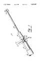
- FIG. 1is a perspective view of a prior-art surgical instrument.
- FIG. 2is a perspective view of a the surgical instrument according to the present invention.
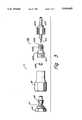
- FIG. 3is an exploded view of the component parts of the present invention, and depicts the interrelationship of the component parts.
- FIG. 4is a partial longitudinal section view of a portion of the surgical instrument according to the present invention.
- Surgical instrument 11comprises a fluid-driven motor 13, which is connected to a source of pressurized fluid by a fluid conduit 15.
- Motor 13terminates at one end thereof in a rotatable shaft 17, which is rotated by motor 13 in response to fluid pressure.
- Shaft 17terminates in a chuck 19, in this case a conventional collet arrangement including a collet nut 19a, which is secured by threads to a collet formed (not shown) on the end of shaft 17.
- Chuck 19serves as a means to secure a dissecting tool to shaft 17 of motor 13.
- a base 21is releasably coupled to motor 13, in this case by threads.
- Base 21functions as a shroud to cover chuck 19 and shaft 17 during operation thereby protecting the user from exposure to these moving parts.
- a support sleeve 25is secured to base 21.
- Support sleeve 25serves to laterally and rotationally support and lend structural integrity to the otherwise flexible shaft 27 of a dissecting tool 29.
- Sleeve 25is conventional in every respect, and includes a tubular member, which may contain bearings or the like to facilitate rotation of shaft 27 of dissecting tool 29 within sleeve 25.
- sleeve 25is fixedly or immovably secured to base 21. More specifically, to disengage dissecting tool 29 from shaft 17 of motor 13, access to chuck assembly 19 must be had. To obtain such access, base 21 must be uncoupled from motor 13 and moved outwardly along shaft 27 of dissecting tool 29 a distance D. If dissecting tool 29 terminates in a cutting head larger in diameter than shaft 27 as shown, sleeve 25 cannot be moved beyond this cutting head. Therefore, even in the partially disassembled state illustrated in FIG. 1, enlarged cutting head of dissecting tool 29 must protrude beyond the end of sleeve 25 some distance d that must be greater than or equal to zero. Access to chuck 19 is necessary to permit insertion of anti-rotation rod 31 into a mating hole in rotatable shaft 17, to secure shaft 17 against rotation and to permit use of a wrench to loosen and tighten chuck 19.
- Surgical instrument 111is provided with a fluid-driven motor 113, which is in fluid communication with a source of pressurized fluid (not shown) through fluid conduit 115.
- a base 121is coupled, in this case by internal threads, to an end of motor 113, and serves to cover the chuck assembly (not shown).
- a conventional sleeve 125is movably secured to base 121 by means of a collet assembly 123. Sleeve 125 serves to laterally and rotationally support shaft 127 of dissecting tool 129.
- FIG. 3depicts an exploded view of surgical instrument 111, which illustrates the interrelationship of the component parts of surgical instrument 111, particularly the components of collet assembly 123.
- base 121is shown uncoupled from motor 113 to expose rotatable shaft 117 and chuck assembly 119.
- Collet assembly 123is shown removed from base 121 to illustrate the component parts thereof.
- Collet assembly 123includes collet nut 123a, which has a bore therethrough to accommodate sleeve 125, and is internally threaded for engagement with a collet 123b.
- Collet 123bdefines a plurality of collet fingers 123c, which are exteriorly threaded at 123d for engagement with the internal threads of collet nut 123a.
- Collet 123bhas a longitudinal bore therethrough to receive and engage the exterior of sleeve 125.
- Collet 123bis further provided with a lock ring 123e, which is received interiorly of the longitudinal bore through collet 123b and serves to limit the travel of sleeve 125 through the internal longitudinal bore of collet 123b.
- Collet 123bis secured to internal threads in base 121 by means of external threads 124.
- Collet assembly 123is selectively engageable about the exterior of sleeve 125 to permit selective axial movement of sleeve 125 relative to base 121 and shaft 127 of dissecting tool 129.
- shaft 127 of dissecting tool 129is releasably engaged in chuck 119 and is constrained against axial movement relative to motor 113, shaft 127, and base 121.
- Collet assembly 123is illustrated as only a preferred means for selectively permitting axial movement of sleeve 125 relative to base 121 and shaft 127 of dissecting tool 129, and for tightly securing sleeve 125 in a desired position.
- FIG. 4is a partial longitudinal section view of the collet assembly 123 of FIG. 3, shown fully assembled.
- Collet assembly 123is illustrated with collet nut 123a assembled over and fully tightened on threads 123d of collet 123b.
- Inclined surfaces on the interior of collet nut 123a and collet fingers 123ccooperate to permit collet fingers 123c to engage the exterior of sleeve 125 securely, thus preventing relative movement between sleeve 125 and collet assembly 123 and base 121.
- Sleeve 125is shown fully retracted in base 121, wherein lock ring 123e or strap means abuts the end of sleeve 125 and prevents further inward movement of sleeve 125 within base 121.
- Shaft 129 of dissecting tool 127extends from sleeve 125 into engagement with chuck (119 in FIG. 2), for rotation thereof by motor (113 in FIG. 2).
- Collet nut 123amay be loosened from engagement with collet fingers 123c to permit relative movement between sleeve 125 and base 121 in other modes of operation of the invention not illustrated herein.
- surgical instrument 111In normal dissecting operation, surgical instrument 111 is fully assembled as is generally depicted in FIG. 2. In this normal mode of operation, pressurized fluid is supplied from fluid conduit 115 to fluid-driven motor 113 for rotation of dissecting tool 129. Thus, bone may be dissected by application of rotating dissecting tool 129 to the area desired to be dissected.
- dissecting tool 129At some point during dissection operation, it may become desirable to remove and/or replace dissecting tool 129, either because dissecting tool 129 has become dull, or because a dissecting tool of a different configuration is desirable. At this point, it is necessary to gain access to chuck 119 and shaft 117 to permit shaft 127 of dissecting tool 129 to be disengaged from chuck 119.
- Collet assembly 123is released by rotating collet nut 123a to disengage collet fingers 123c of collet 123b from frictional engagement with the exterior of sleeve 125.
- sleeve 125may be moved axially inwardly within base 121 to increase the amount of shaft 127 of dissecting tool 129 that extends or protrudes beyond the end of sleeve 125.
- Normally sleeve 125is fully retracted in base 121 until the end thereof abuts lock ring 123e of collet assembly 123.
- base 121is unscrewed from motor 113 to permit access to chuck assembly 119, preferably by unscrewing the threads therebetween.
- Base 121then is moved outwardly from motor 113 and along and relative to shaft 127 of dissecting tool 129. The outward movement of base 121 relative to motor 113 exposes rotatable shaft 117 and chuck assembly 119.
- Sleeve 125will move outward relative to shaft 127 along with base 121.
- An anti-rotation rod(31 in FIG. 1) then is inserted through hole in shaft 117 to secure rotatable shaft 117 against rotation.
- a wrench or other similar toolthen is engaged about chuck assembly 119 to loosen chuck and permit removal of dissecting tool 127 from engagement therewith.
- a new dissecting tool, or a tool of differing configuration,then is coupled to rotatable shaft 117 by engagement of chuck assembly 119 about the shaft of the dissecting tool.
- Base 121then is recoupled to motor 113.
- sleeve 125is extended axially outwardly from base 121 to eliminate or reduce the length of exposed and unsupported shaft of the dissecting tool (D+d in FIG. 1).
- sleeve 125may be secured or constrained against further axial movement relative to base 121 by engagement of collet assembly 123 with the exterior of sleeve 125.
- engagementis accomplished by tightening collet nut 123a about collet 123b, which in turn secures collet fingers 123c in frictional engagement with the exterior of sleeve 125, thereby constraining sleeve 125 against further axial movement relative to base 121.
- Dissecting operationthen may be recommenced using surgical tool 111 according to the present invention.
- the surgical instrument according to the present inventionhas a number of advantages.
- a principal advantageis that removal and replacement of dissecting tools for use with the surgical instrument is facilitated and expedited. Also, removal and replacement of dissecting tools may be relatively easily accomplished with a selected amount of extension or protrusion of the shaft of the dissecting tool beyond the end of the sleeve. Thus, a surgical instrument is provided that is more easily manipulated.
Landscapes
- Health & Medical Sciences (AREA)
- Surgery (AREA)
- Life Sciences & Earth Sciences (AREA)
- Biomedical Technology (AREA)
- Medical Informatics (AREA)
- Orthopedic Medicine & Surgery (AREA)
- Oral & Maxillofacial Surgery (AREA)
- Engineering & Computer Science (AREA)
- Dentistry (AREA)
- Heart & Thoracic Surgery (AREA)
- Nuclear Medicine, Radiotherapy & Molecular Imaging (AREA)
- Molecular Biology (AREA)
- Animal Behavior & Ethology (AREA)
- General Health & Medical Sciences (AREA)
- Public Health (AREA)
- Veterinary Medicine (AREA)
- Surgical Instruments (AREA)
Abstract
Description
Claims (7)
Priority Applications (1)
| Application Number | Priority Date | Filing Date | Title |
|---|---|---|---|
| US08/025,085US5439005A (en) | 1993-03-02 | 1993-03-02 | Surgical instrument with telescoping sleeve |
Applications Claiming Priority (1)
| Application Number | Priority Date | Filing Date | Title |
|---|---|---|---|
| US08/025,085US5439005A (en) | 1993-03-02 | 1993-03-02 | Surgical instrument with telescoping sleeve |
Publications (1)
| Publication Number | Publication Date |
|---|---|
| US5439005Atrue US5439005A (en) | 1995-08-08 |
Family
ID=21823959
Family Applications (1)
| Application Number | Title | Priority Date | Filing Date |
|---|---|---|---|
| US08/025,085Expired - LifetimeUS5439005A (en) | 1993-03-02 | 1993-03-02 | Surgical instrument with telescoping sleeve |
Country Status (1)
| Country | Link |
|---|---|
| US (1) | US5439005A (en) |
Cited By (42)
| Publication number | Priority date | Publication date | Assignee | Title |
|---|---|---|---|---|
| US5609573A (en)* | 1996-02-28 | 1997-03-11 | Conmed Corporation | Electrosurgical suction/irrigation instrument |
| US5794715A (en)* | 1996-07-08 | 1998-08-18 | Linvatec Corporation | Rotary tool head |
| WO1998035621A1 (en)* | 1997-02-13 | 1998-08-20 | Mednext Inc. | Adjustable depth drill guide |
| US5827280A (en)* | 1996-03-19 | 1998-10-27 | Conmed Corporation | Device for locking a protective endoscopic electrode sleeve |
| US6033408A (en)* | 1996-07-30 | 2000-03-07 | Midas Rex, L.P. | Resecting tool for magnetic field environment |
| US6209886B1 (en) | 1999-04-30 | 2001-04-03 | Medtronic, Inc. | Resecting tool with independent variable axial extension for tool implements and guide sleeves |
| US20020165549A1 (en)* | 2001-04-30 | 2002-11-07 | Medtronic, Inc. | Surgical instrument and attachment |
| US6520976B1 (en) | 1999-04-30 | 2003-02-18 | Medtronic, Inc. | Modular hand control for pneumatic resecting tool |
| US20030083681A1 (en)* | 2001-09-17 | 2003-05-01 | Moutafis Timothy E. | Surgical rotary abrader |
| US6645219B2 (en)* | 2001-09-07 | 2003-11-11 | Amira Medical | Rotatable penetration depth adjusting arrangement |
| US20030220646A1 (en)* | 2002-05-23 | 2003-11-27 | Thelen Sarah L. | Method and apparatus for reducing femoral fractures |
| US20040122460A1 (en)* | 2002-12-20 | 2004-06-24 | Medtronic, Inc. | Surgical instrument with telescoping attachment |
| US20040215203A1 (en)* | 1996-07-31 | 2004-10-28 | Michelson Gary K. | Bone removal device |
| US20050031424A1 (en)* | 2003-08-08 | 2005-02-10 | Hernandez Hector Ray | Reversible drill and drive tool |
| US20060043685A1 (en)* | 2004-08-25 | 2006-03-02 | Burton Kozak | Universal bit and tool holder for a linear-to-rotational motion converting device |
| US20060095045A1 (en)* | 2004-11-01 | 2006-05-04 | Sdgi Holdings, Inc. | Methods for explantation of intervertebral disc implants |
| US20060178672A1 (en)* | 2002-12-20 | 2006-08-10 | Medtronic, Inc. D/B/A Medtronic Midas Rex | Surgical instrument with angled attachment |
| US20060229624A1 (en)* | 2005-03-31 | 2006-10-12 | Zimmer Technology, Inc. | Orthopaedic cutting instrument and method |
| US20060233622A1 (en)* | 2003-12-23 | 2006-10-19 | Bauman Lynn E | A bit holding apparatus for use with a power tool |
| US20060248624A1 (en)* | 2005-04-25 | 2006-11-09 | Pieczynski Darren E | Heat containment hand warming device |
| US20080064921A1 (en)* | 2006-06-13 | 2008-03-13 | Intuitive Surgical, Inc. | Guide tube control of minimally invasive surgical instruments |
| US20080226407A1 (en)* | 2003-12-23 | 2008-09-18 | Lynn E. Bauman | Bit holding apparatus for use with a power tool |
| US20090275858A1 (en)* | 2008-05-02 | 2009-11-05 | Hardin Terry D | Adjustable spacer |
| US20090278324A1 (en)* | 2007-03-15 | 2009-11-12 | Peter Chen | Tool chucking apparatus |
| US20090326322A1 (en)* | 2008-06-27 | 2009-12-31 | Intuitive Surgical, Inc. | Medical robotic system with image referenced camera control using partitionable orientational and translational modes |
| US20100249786A1 (en)* | 2009-03-30 | 2010-09-30 | Reinhold Schmieding | Microfracture instrument |
| US8292150B2 (en) | 2010-11-02 | 2012-10-23 | Tyco Healthcare Group Lp | Adapter for powered surgical devices |
| US9119685B2 (en) | 2012-10-08 | 2015-09-01 | Warsaw Orthopedic, Inc. | Surgical instrument and method |
| US20160052062A1 (en)* | 2014-08-20 | 2016-02-25 | Simtek Ag | Tool holder |
| US9572605B2 (en) | 2012-10-09 | 2017-02-21 | Warsaw Orthopedic, Inc. | Surgical instrument and method |
| USD782042S1 (en) | 2015-03-25 | 2017-03-21 | Medtronic Ps Medical, Inc. | Surgical tool |
| USD790699S1 (en) | 2015-03-25 | 2017-06-27 | Medtronic Ps Medical, Inc. | Surgical tool |
| US20170265909A1 (en)* | 2011-10-21 | 2017-09-21 | Amendia, Inc. | Facet Screw System and Method |
| USD800903S1 (en) | 2016-02-09 | 2017-10-24 | Medtronic Ps Medical, Inc. | Surgical tool |
| USD800906S1 (en) | 2015-03-25 | 2017-10-24 | Medtronic Ps Medical, Inc. | Surgical tool |
| USD800907S1 (en) | 2015-03-25 | 2017-10-24 | Medtronic Ps Medical, Inc. | Surgical tool |
| US9949750B2 (en) | 2011-10-31 | 2018-04-24 | Boston Scientific Scimed, Inc. | Rotatable medical device |
| US10015951B2 (en)* | 2014-05-01 | 2018-07-10 | Bow Wow Labs, Inc. | Pet treat holder and safety device |
| US10080579B2 (en) | 2015-03-25 | 2018-09-25 | Medtronic Ps Medical, Inc. | Pin drive rotary surgical cutting tools and powered handpieces |
| US10314610B2 (en) | 2015-03-25 | 2019-06-11 | Medtronic Ps Medical, Inc. | Slanted drive axis rotary surgical cutting tools and powered handpieces |
| US10849634B2 (en) | 2018-06-20 | 2020-12-01 | Medtronic Xomed, Inc. | Coupling portion for rotary surgical cutting systems |
| US12440902B2 (en) | 2024-01-08 | 2025-10-14 | Medtronic Ps Medical, Inc. | Pin drive rotary surgical cutting tools and powered handpieces |
Citations (6)
| Publication number | Priority date | Publication date | Assignee | Title |
|---|---|---|---|---|
| US2710000A (en)* | 1952-02-19 | 1955-06-07 | Cromer Jeremiah Keith | Cutting instrument |
| US3128768A (en)* | 1961-11-24 | 1964-04-14 | Rosemount Eng Co Ltd | Surgical drill |
| US3384085A (en)* | 1964-07-03 | 1968-05-21 | Robert M. Hall | Surgical cutting tool |
| USRE27032E (en)* | 1969-05-27 | 1971-01-19 | Surgical cuttinli tool | |
| US4111208A (en)* | 1976-12-22 | 1978-09-05 | Roland Leuenberger | Process for drilling holes in hard materials, in surgical procedures, and apparatus for carrying out the process |
| US4512344A (en)* | 1982-05-12 | 1985-04-23 | Barber Forest C | Arthroscopic surgery dissecting apparatus |
- 1993
- 1993-03-02USUS08/025,085patent/US5439005A/ennot_activeExpired - Lifetime
Patent Citations (6)
| Publication number | Priority date | Publication date | Assignee | Title |
|---|---|---|---|---|
| US2710000A (en)* | 1952-02-19 | 1955-06-07 | Cromer Jeremiah Keith | Cutting instrument |
| US3128768A (en)* | 1961-11-24 | 1964-04-14 | Rosemount Eng Co Ltd | Surgical drill |
| US3384085A (en)* | 1964-07-03 | 1968-05-21 | Robert M. Hall | Surgical cutting tool |
| USRE27032E (en)* | 1969-05-27 | 1971-01-19 | Surgical cuttinli tool | |
| US4111208A (en)* | 1976-12-22 | 1978-09-05 | Roland Leuenberger | Process for drilling holes in hard materials, in surgical procedures, and apparatus for carrying out the process |
| US4512344A (en)* | 1982-05-12 | 1985-04-23 | Barber Forest C | Arthroscopic surgery dissecting apparatus |
Cited By (82)
| Publication number | Priority date | Publication date | Assignee | Title |
|---|---|---|---|---|
| US5609573A (en)* | 1996-02-28 | 1997-03-11 | Conmed Corporation | Electrosurgical suction/irrigation instrument |
| US5827280A (en)* | 1996-03-19 | 1998-10-27 | Conmed Corporation | Device for locking a protective endoscopic electrode sleeve |
| US5794715A (en)* | 1996-07-08 | 1998-08-18 | Linvatec Corporation | Rotary tool head |
| US6033408A (en)* | 1996-07-30 | 2000-03-07 | Midas Rex, L.P. | Resecting tool for magnetic field environment |
| US7083623B2 (en) | 1996-07-31 | 2006-08-01 | Sdgi Holdings, Inc. | Milling instrumentation and method for preparing a space between adjacent vertebral bodies |
| US8663232B2 (en) | 1996-07-31 | 2014-03-04 | Warsaw Orthopedic, Inc. | Apparatus and method for creating an implantation space in a spine |
| US7635370B2 (en) | 1996-07-31 | 2009-12-22 | Warsaw Orthopedic, Inc. | Bone removal device |
| US20040249388A1 (en)* | 1996-07-31 | 2004-12-09 | Michelson Gary K. | Distractor with opening |
| US20040215203A1 (en)* | 1996-07-31 | 2004-10-28 | Michelson Gary K. | Bone removal device |
| US8066709B2 (en) | 1996-07-31 | 2011-11-29 | Warsaw Orthopedic, Inc. | Distractor with opening |
| US5810828A (en)* | 1997-02-13 | 1998-09-22 | Mednext, Inc. | Adjustable depth drill guide |
| WO1998035621A1 (en)* | 1997-02-13 | 1998-08-20 | Mednext Inc. | Adjustable depth drill guide |
| US6209886B1 (en) | 1999-04-30 | 2001-04-03 | Medtronic, Inc. | Resecting tool with independent variable axial extension for tool implements and guide sleeves |
| US6520976B1 (en) | 1999-04-30 | 2003-02-18 | Medtronic, Inc. | Modular hand control for pneumatic resecting tool |
| US20070123995A1 (en)* | 2000-03-07 | 2007-05-31 | Zimmer Technology, Inc. | Method and apparatus for reducing femoral fractures |
| US20020165549A1 (en)* | 2001-04-30 | 2002-11-07 | Medtronic, Inc. | Surgical instrument and attachment |
| US6645219B2 (en)* | 2001-09-07 | 2003-11-11 | Amira Medical | Rotatable penetration depth adjusting arrangement |
| US20030083681A1 (en)* | 2001-09-17 | 2003-05-01 | Moutafis Timothy E. | Surgical rotary abrader |
| US20030220646A1 (en)* | 2002-05-23 | 2003-11-27 | Thelen Sarah L. | Method and apparatus for reducing femoral fractures |
| US8518065B2 (en)* | 2002-12-20 | 2013-08-27 | Medtronic, Inc. | Surgical instrument with telescoping attachment |
| US20080208195A1 (en)* | 2002-12-20 | 2008-08-28 | Medtronic, Inc. | Surgical Instrument With Telescoping Attachment |
| US20060178672A1 (en)* | 2002-12-20 | 2006-08-10 | Medtronic, Inc. D/B/A Medtronic Midas Rex | Surgical instrument with angled attachment |
| US9066729B2 (en)* | 2002-12-20 | 2015-06-30 | Medtronic, Inc. | Surgical instrument with telescoping attachment |
| US20040122460A1 (en)* | 2002-12-20 | 2004-06-24 | Medtronic, Inc. | Surgical instrument with telescoping attachment |
| FR2848807A1 (en)* | 2002-12-20 | 2004-06-25 | Medtronic Inc | Surgical dissection tool for bone and tissue, has coupler that includes tool collet and attachment locking mechanism operable to permit tool collet operation and telescoping movement of an attachment tube with respect to the dissection tool |
| US7559927B2 (en) | 2002-12-20 | 2009-07-14 | Medtronic Xomed, Inc. | Surgical instrument with telescoping attachment |
| US7549992B2 (en) | 2002-12-20 | 2009-06-23 | Medtronic, Inc. | Surgical instrument with angled attachment |
| US7237987B2 (en)* | 2003-08-08 | 2007-07-03 | Alltrade Tools Llc | Reversible drill and drive tool |
| US20050031424A1 (en)* | 2003-08-08 | 2005-02-10 | Hernandez Hector Ray | Reversible drill and drive tool |
| US8132990B2 (en) | 2003-12-23 | 2012-03-13 | Lynn Everett Bauman | Bit holding apparatus for use with a power tool |
| US20080226407A1 (en)* | 2003-12-23 | 2008-09-18 | Lynn E. Bauman | Bit holding apparatus for use with a power tool |
| US7374377B2 (en)* | 2003-12-23 | 2008-05-20 | Patrick Anderson | Bit holding apparatus for use with a power tool |
| US20060233622A1 (en)* | 2003-12-23 | 2006-10-19 | Bauman Lynn E | A bit holding apparatus for use with a power tool |
| US20060043685A1 (en)* | 2004-08-25 | 2006-03-02 | Burton Kozak | Universal bit and tool holder for a linear-to-rotational motion converting device |
| WO2006050310A1 (en)* | 2004-11-01 | 2006-05-11 | Sdgi Holdings, Inc. | Methods and devices for explantation of intervertebral disc implants |
| US20060095045A1 (en)* | 2004-11-01 | 2006-05-04 | Sdgi Holdings, Inc. | Methods for explantation of intervertebral disc implants |
| US7922720B2 (en) | 2005-03-31 | 2011-04-12 | Zimmer Technology, Inc. | Orthopaedic cutting instrument and method |
| US20060229624A1 (en)* | 2005-03-31 | 2006-10-12 | Zimmer Technology, Inc. | Orthopaedic cutting instrument and method |
| US20090177202A1 (en)* | 2005-03-31 | 2009-07-09 | Zimmer Technology, Inc. | Orthopaedic cutting instrument and method |
| US20060248624A1 (en)* | 2005-04-25 | 2006-11-09 | Pieczynski Darren E | Heat containment hand warming device |
| US8740885B2 (en) | 2006-06-13 | 2014-06-03 | Intuitive Surgical Operations, Inc. | Guide tube control of minimally invasive surgical instrument |
| US20080064921A1 (en)* | 2006-06-13 | 2008-03-13 | Intuitive Surgical, Inc. | Guide tube control of minimally invasive surgical instruments |
| US20090278324A1 (en)* | 2007-03-15 | 2009-11-12 | Peter Chen | Tool chucking apparatus |
| US8888420B2 (en)* | 2007-03-15 | 2014-11-18 | Primetool Mfg, Inc. | Tool chucking apparatus |
| US8043316B2 (en)* | 2008-05-02 | 2011-10-25 | Suros Surgical Systems, Inc. | Adjustable spacer |
| US20090275858A1 (en)* | 2008-05-02 | 2009-11-05 | Hardin Terry D | Adjustable spacer |
| US10582838B2 (en) | 2008-06-27 | 2020-03-10 | Intuitive Surgical Operations, Inc. | Medical robotic system with image referenced camera control using partitionable orientational and translational modes |
| US9955859B2 (en) | 2008-06-27 | 2018-05-01 | Intuitive Surgical Operations, Inc. | Medical robotic system with image referenced camera control using partitionable orientational and translational modes |
| US20090326322A1 (en)* | 2008-06-27 | 2009-12-31 | Intuitive Surgical, Inc. | Medical robotic system with image referenced camera control using partitionable orientational and translational modes |
| US11284782B2 (en) | 2008-06-27 | 2022-03-29 | Intuitive Surgical Operations, Inc. | System and method for multi-mode imaging device control |
| US11969147B2 (en) | 2008-06-27 | 2024-04-30 | Intuitive Surgical Operations, Inc. | System and method for multi-mode imaging device control |
| US9179832B2 (en) | 2008-06-27 | 2015-11-10 | Intuitive Surgical Operations, Inc. | Medical robotic system with image referenced camera control using partitionable orientational and translational modes |
| US20100249786A1 (en)* | 2009-03-30 | 2010-09-30 | Reinhold Schmieding | Microfracture instrument |
| US8852201B2 (en)* | 2009-03-30 | 2014-10-07 | Arthrex, Inc. | Microfracture instrument |
| US9282963B2 (en) | 2010-11-02 | 2016-03-15 | Covidien Lp | Adapter for powered surgical devices |
| US10004504B2 (en) | 2010-11-02 | 2018-06-26 | Covidien Lp | Adapter for powered surgical devices |
| US10758235B2 (en) | 2010-11-02 | 2020-09-01 | Covidien Lp | Adapter for powered surgical devices |
| US8292150B2 (en) | 2010-11-02 | 2012-10-23 | Tyco Healthcare Group Lp | Adapter for powered surgical devices |
| US10314622B2 (en)* | 2011-10-21 | 2019-06-11 | Amendia, Inc. | Facet screw system and method |
| US11583321B2 (en)* | 2011-10-21 | 2023-02-21 | Spinal Elements, Inc. | Facet screw system and method |
| US20170265909A1 (en)* | 2011-10-21 | 2017-09-21 | Amendia, Inc. | Facet Screw System and Method |
| US9949750B2 (en) | 2011-10-31 | 2018-04-24 | Boston Scientific Scimed, Inc. | Rotatable medical device |
| US10390854B2 (en) | 2011-10-31 | 2019-08-27 | Boston Scientific Scimed, Inc. | Rotatable medical device |
| US9119685B2 (en) | 2012-10-08 | 2015-09-01 | Warsaw Orthopedic, Inc. | Surgical instrument and method |
| US9572605B2 (en) | 2012-10-09 | 2017-02-21 | Warsaw Orthopedic, Inc. | Surgical instrument and method |
| US10856528B2 (en) | 2014-05-01 | 2020-12-08 | Bow Wow Labs, Inc. | Pet treat holder and safety device |
| US10015951B2 (en)* | 2014-05-01 | 2018-07-10 | Bow Wow Labs, Inc. | Pet treat holder and safety device |
| US9993880B2 (en)* | 2014-08-20 | 2018-06-12 | Simtek Ag | Tool holder |
| US20160052062A1 (en)* | 2014-08-20 | 2016-02-25 | Simtek Ag | Tool holder |
| US10905453B2 (en) | 2015-03-25 | 2021-02-02 | Medtronic Ps Medical, Inc. | Pin drive rotary surgical cutting tools and powered handpieces |
| USD800907S1 (en) | 2015-03-25 | 2017-10-24 | Medtronic Ps Medical, Inc. | Surgical tool |
| USD800906S1 (en) | 2015-03-25 | 2017-10-24 | Medtronic Ps Medical, Inc. | Surgical tool |
| US10314610B2 (en) | 2015-03-25 | 2019-06-11 | Medtronic Ps Medical, Inc. | Slanted drive axis rotary surgical cutting tools and powered handpieces |
| US11154319B2 (en) | 2015-03-25 | 2021-10-26 | Medtronic Ps Medical, Inc. | Slanted drive axis rotary surgical cutting tools and powered handpieces |
| USD790699S1 (en) | 2015-03-25 | 2017-06-27 | Medtronic Ps Medical, Inc. | Surgical tool |
| USD782042S1 (en) | 2015-03-25 | 2017-03-21 | Medtronic Ps Medical, Inc. | Surgical tool |
| US11864784B2 (en) | 2015-03-25 | 2024-01-09 | Medtronic Ps Medical, Inc. | Pin drive rotary surgical cutting tools and powered handpieces |
| US10080579B2 (en) | 2015-03-25 | 2018-09-25 | Medtronic Ps Medical, Inc. | Pin drive rotary surgical cutting tools and powered handpieces |
| USD800903S1 (en) | 2016-02-09 | 2017-10-24 | Medtronic Ps Medical, Inc. | Surgical tool |
| US10849634B2 (en) | 2018-06-20 | 2020-12-01 | Medtronic Xomed, Inc. | Coupling portion for rotary surgical cutting systems |
| US12137918B2 (en) | 2018-06-20 | 2024-11-12 | Medtronic Xomed, Inc. | Coupling portion for rotary surgical cutting systems |
| US12440902B2 (en) | 2024-01-08 | 2025-10-14 | Medtronic Ps Medical, Inc. | Pin drive rotary surgical cutting tools and powered handpieces |
Similar Documents
| Publication | Publication Date | Title |
|---|---|---|
| US5439005A (en) | Surgical instrument with telescoping sleeve | |
| US5888200A (en) | Multi-purpose surgical tool system | |
| EP1511432B1 (en) | Surgical instrument with a collet locking and indexing system | |
| US5735854A (en) | Device for applying a screw | |
| US5505737A (en) | Quick release coupling for a dissecting tool | |
| US6540739B2 (en) | Surgical instrumentation system | |
| US5465983A (en) | Removable nosepieces for chucks and similar tool holders | |
| US5741263A (en) | Mutiple flat quick release coupling | |
| WO1998005261A9 (en) | Multi-purpose surgical tool system | |
| US20080208195A1 (en) | Surgical Instrument With Telescoping Attachment | |
| JPS62114884A (en) | Driver particularly for surgery | |
| US4260381A (en) | Dental handpiece | |
| WO1995018573A1 (en) | Microsurgery instrument | |
| WO2003011533B1 (en) | Battery powered screwdriver and screw starting device | |
| US20070087306A1 (en) | Clamping device and dental handpiece including same | |
| TW376310B (en) | Endoscopic kit for ligation | |
| US4519108A (en) | Combination tool | |
| US4939834A (en) | Machine tool with tool change mechanism | |
| EP0849052A2 (en) | Throttle air inlet for a pneumatic tool | |
| ATE287771T1 (en) | BAYONET ROLL END ADAPTER | |
| CN222018361U (en) | Hand-held instrument with separable and replaceable tail end | |
| JP3085105B2 (en) | Tama net | |
| JP3448093B2 (en) | Screw fastening tool | |
| CN214966823U (en) | Novel medical and American surgical instrument anti-falling bracelet | |
| JPH07301751A (en) | Rigid sleeve device for endoscope |
Legal Events
| Date | Code | Title | Description |
|---|---|---|---|
| AS | Assignment | Owner name:MIDAS REX PNEUMATIC TOOLS, INC., TEXAS Free format text:ASSIGNMENT OF ASSIGNORS INTEREST.;ASSIGNOR:VAUGHN, WILLIAM J.;REEL/FRAME:006480/0072 Effective date:19930301 | |
| STCF | Information on status: patent grant | Free format text:PATENTED CASE | |
| AS | Assignment | Owner name:MIDAS REX, L.P., TEXAS Free format text:ASSIGNMENT OF ASSIGNORS INTEREST;ASSIGNOR:MIDAS REX PNEUMATIC TOOLS, INC., A CORPORATION OF TEXAS;REEL/FRAME:009089/0684 Effective date:19980317 | |
| FEPP | Fee payment procedure | Free format text:PAT HLDR NO LONGER CLAIMS SMALL ENT STAT AS SMALL BUSINESS (ORIGINAL EVENT CODE: LSM2); ENTITY STATUS OF PATENT OWNER: LARGE ENTITY | |
| REFU | Refund | Free format text:REFUND - PAYMENT OF MAINTENANCE FEE, 4TH YR, SMALL ENTITY (ORIGINAL EVENT CODE: R283); ENTITY STATUS OF PATENT OWNER: LARGE ENTITY | |
| FPAY | Fee payment | Year of fee payment:4 | |
| FEPP | Fee payment procedure | Free format text:PAYOR NUMBER ASSIGNED (ORIGINAL EVENT CODE: ASPN); ENTITY STATUS OF PATENT OWNER: LARGE ENTITY | |
| FPAY | Fee payment | Year of fee payment:8 | |
| FPAY | Fee payment | Year of fee payment:12 |