US5438938A - Cart with removable tray assembly - Google Patents
Cart with removable tray assemblyDownload PDFInfo
- Publication number
- US5438938A US5438938AUS08/182,445US18244594AUS5438938AUS 5438938 AUS5438938 AUS 5438938AUS 18244594 AUS18244594 AUS 18244594AUS 5438938 AUS5438938 AUS 5438938A
- Authority
- US
- United States
- Prior art keywords
- tray
- frame
- tray assembly
- utility cart
- latch
- Prior art date
- Legal status (The legal status is an assumption and is not a legal conclusion. Google has not performed a legal analysis and makes no representation as to the accuracy of the status listed.)
- Expired - Lifetime
Links
- 230000008878couplingEffects0.000claimsabstract8
- 238000010168coupling processMethods0.000claimsabstract8
- 238000005859coupling reactionMethods0.000claimsabstract8
- 230000014759maintenance of locationEffects0.000claimsdescription27
- 230000000712assemblyEffects0.000description30
- 238000000429assemblyMethods0.000description30
- 210000004247handAnatomy0.000description4
- 230000000694effectsEffects0.000description2
- 210000003811fingerAnatomy0.000description2
- 239000000463materialSubstances0.000description2
- 235000012054mealsNutrition0.000description2
- 238000009434installationMethods0.000description1
- 239000011159matrix materialSubstances0.000description1
- 238000012986modificationMethods0.000description1
- 230000004048modificationEffects0.000description1
- 230000002787reinforcementEffects0.000description1
- 210000003813thumbAnatomy0.000description1
Images


Classifications
- A—HUMAN NECESSITIES
- A47—FURNITURE; DOMESTIC ARTICLES OR APPLIANCES; COFFEE MILLS; SPICE MILLS; SUCTION CLEANERS IN GENERAL
- A47B—TABLES; DESKS; OFFICE FURNITURE; CABINETS; DRAWERS; GENERAL DETAILS OF FURNITURE
- A47B31/00—Service or tea tables, trolleys, or wagons
- A—HUMAN NECESSITIES
- A47—FURNITURE; DOMESTIC ARTICLES OR APPLIANCES; COFFEE MILLS; SPICE MILLS; SUCTION CLEANERS IN GENERAL
- A47B—TABLES; DESKS; OFFICE FURNITURE; CABINETS; DRAWERS; GENERAL DETAILS OF FURNITURE
- A47B23/00—Bed-tables; Trays; Reading-racks; Book-rests, i.e. items used in combination with something else
- A47B23/001—Trays, e.g. with foldable legs
- A—HUMAN NECESSITIES
- A47—FURNITURE; DOMESTIC ARTICLES OR APPLIANCES; COFFEE MILLS; SPICE MILLS; SUCTION CLEANERS IN GENERAL
- A47B—TABLES; DESKS; OFFICE FURNITURE; CABINETS; DRAWERS; GENERAL DETAILS OF FURNITURE
- A47B31/00—Service or tea tables, trolleys, or wagons
- A47B2031/004—Service or tea tables, trolleys, or wagons having four vertical uprights
Definitions
- the present inventionrelates to a cart and, in particular, to a cart having a frame that includes at least one shelf and a tray assembly coupled to the frame above the shelf. More particularly, the present invention relates to a tray assembly that is removable from the cart frame so that the tray assembly can be used as a serving tray or lap tray away from the cart.
- Shelf structures and cartshave a variety of uses around a home, office, or other work place. These devices typically include vertically extending legs to which one or more fixed shelves are attached. The legs and shelves together form a frame. Each shelf includes a surface on which items may be placed for display and storage.
- Cartsoften include wheeled casters that are attached to the lower end of each of the legs. These wheeled casters enhance the mobility of a cart so that the items on the cart shelves can be simultaneously and more easily transported from one location to another by a user pushing the cart.
- Transferring items from a cart shelf to a separate tray to expedite delivery of the itemscan be a cumbersome and time-consuming activity. If many items must be transferred, someone must find a place to set the tray next to the cart and the time and place to move the items from the cart shelf to the separate serving tray. Individual transfer of several items from a cart to a serving tray can involve considerable expenditure of time and, thus, quickly becomes inefficient. Another problem arises if additional tray storage space is not available to hold a tray when such tray is not in use.
- tray assembliestypically include a tray having a table surface and a bottom surface.
- One type of tray assemblyincludes support legs on the bottom surface to elevate its table surface and another type of tray assembly has a generally flat bottom surface without any support legs.
- Free-standing tray assembliestypically include two or more support legs coupled to the bottom surface of the tray.
- Short free-standing tray assembliesare used for such things as bed trays where a meal on the table surface of the tray can be enjoyed by an individual who is bedridden due to an illness.
- Tall free-standing traysare used as "TV trays" where an individual can enjoy a meal in a relaxed setting away from a dining room.
- tray support legsare movable from a retracted position, where the legs are folded to lie flat against the bottom surface of the tray, to an extended position, where the legs are unfolded to project at an angle away from the bottom surface of the tray. The retracted position allows the tray assembly to be stored more easily, while the extended position allows the tray assembly to be self-supporting.
- tray assembliesfree-standing or otherwise, are that they must be stored when not in use. Adequate storage space or a special rack must be provided to hold such tray assemblies when not in use. Both storage space and tray racks add to the expense associated with tray assemblies.
- a cart or other shelf structure that incorporated a removable tray assembly as one of its shelveswould allow the advantages of both to be exploited while, at the same time, reducing the above-described disadvantages associated with using separate carts and trays.
- Transportable itemscould be initially stored on the table surface of the tray assembly mounted on the cart. These items could be moved away from the cart, when desired, by removing the tray assembly from the cart frame and moving the tray to the desired location.
- the remaining shelves of the shelf structure or cartwould still be employable for storage and display of other items.
- the frame of the shelf structure or cartwould serve as a mounting fixture on which to store the tray assembly when not in use.
- a shelf structureincludes a frame and a tray assembly.
- the shelf structurefurther includes means for mounting the tray assembly to the frame so that the tray assembly is connected to the frame and means for uncoupling the tray assembly from the frame so that a user can lift the tray assembly off of the frame to disconnect the mounting means from the frame.
- the frameincludes four legs and at least one shelf coupled to the legs so that the frame is a free-standing structure.
- the shelfhas a shelf surface on which items may be placed for storage and display.
- One of the ends of each of the legsmay rest on a floor or other surface for support.
- the shelf structureis a push cart having wheeled casters connected to the support ends of each of the legs of the frame. These wheeled casters allow the cart to be moved easily so that items stored and displayed on the one or more shelf surfaces can be transported from one place to another.
- the tray assemblyincludes a tray having an upwardly facing table surface on which items are placed and a downwardly facing bottom surface.
- the bottom surface of the trayincludes a plurality of leg mounts that are each configured to include a cavity that receives one of the top ends of each of the legs.
- the leg mountsallow the tray assembly to be connected to the top of the shelf structure above the shelf surface of the shelf immediately below to form the top tier of the shelf structure.
- a pair of latch assembliesare attached to the bottom surface of the tray assembly that are configured to couple and uncouple the tray assembly to the frame of the shelf structure.
- Each latch assemblyincludes at least one latch and means for guiding each latch between a locked position engaging the frame to couple the tray assembly to the frame and an unlocked position disengaged from the frame to uncouple the tray assembly from the frame.
- Each leg of the shelf structureis formed to include a latch-receiving slot.
- Each latch assemblyis configured to include a handle. The handle allows the latch or latches of each latch assembly to be manually moved between a locked position engaging one of the latch-receiving slots and an unlocked position disengaging the latch-receiving slot.
- the latch handlesalso provide a convenient means for carrying the tray assembly when it is disconnected from the shelf structure.
- the latch assembliesare biased so that the latches are urged to their locked positions.
- One or more springsare used to bias each of the latches to its locked position.
- Each of these springsis positioned to lie in a spring pocket formed between a latch assembly and the tray bottom surface.
- Each latch of the biased latch assembliesis moved against its spring to its unlocked position.
- the latchesare moved simultaneously to an unlocked position by manually applying a force to each of the handles in a direction generally opposite the force applied by the springs.
- a rounded capis mounted on the top of each leg and each cap is formed to include a latch-receiving slot.
- the rounded top portion of the capacts as a cam and functions to cam each spring-biased latch toward its tray-releasing position during mounting of the tray on the legs.
- the tray assemblyfurther includes a pair of tray stands coupled to the bottom surface of the tray.
- Each tray standis movable between a retracted position adjacent the bottom surface and an extended position supporting the tray.
- the extended positionmakes the tray assembly suitable for use, for example, as a bed or "TV" tray.
- the tray standsare typically moved to the retracted position when the tray is connected to the cart so that they are out of the way of objects stored on the shelf surface of the immediately lower shelf.
- Tray stand clamp assembliescouple the tray stands to the bottom surface of the tray and secure them in the retracted position as well as the extended position.
- Each tray standincludes a pair of legs that are connected together by a cross-brace which is configured to include a raised portion.
- At least one snap lockis cantilevered to the bottom surface of the tray adjacent the position assumed by each cross-brace when the tray stands are in the retracted position. The snap locks engage the raised portions of the cross-braces to help secure the tray stands in the retracted position.
- the tray assemblycan be easily reconnected and coupled to the shelf structure when it is no longer desired to use the tray separately.
- the tray standsare moved to the retracted position.
- a userlocates the tray in a proper position so that the top ends of the legs are inserted into the downwardly facing leg mount cavities of the tray assembly to connect the tray assembly to the frame.
- the userpushes down on the tray so that the latches are moved against their springs to their tray-releasing positions.
- the latchesare urged automatically by their springs to their tray-locking positions into the slots formed in the leg caps. This couples the tray assembly to the frame of the shelf structure.
- FIG. 1is a perspective view of a multi-tiered serving cart with a removable top tray assembly in accordance with the present invention showing a frame including four vertically extending wheeled legs and two lower shelves attached to the legs and a removable tray assembly coupled to the top ends of the legs and positioned to lie above the two lower shelves to form the top tier of the serving
- FIG. 2is a view similar to FIG. 1 showing the underside of the removable tray assembly after it has been uncoupled from the top ends of the four legs following manual movement of the spring-loaded latch assemblies located on a bottom surface of the tray to an unlocked position;
- FIG. 3is a perspective view of the removable tray assembly of FIG. 2 after its support legs have been moved from the retracted position shown in FIG. 2 to a spread-apart extended position;
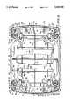
- FIG. 4is a bottom view of the removable tray assembly of FIG. 2 showing a latch assembly at each end of the tray, a pair of H-shaped support legs mounted to the bottom surface of the tray assembly and positioned to lie between the two spaced-apart latch assemblies, and four circular leg mounts adjacent the corners of the bottom surface of the tray;
- FIG. 5is a view taken along line 5--5 of FIG. 4 showing a spring-biased latch of one of the latch assemblies in its tray-locking position engaging a slot formed in a slotted cap appended to the top of one of the frame legs to secure the tray assembly to the top of the cart;
- FIG. 6is a view similar to FIG. 5 showing hand-operated movement of the spring-biased latch to its tray-releasing position to disengage the latch from the slot formed in the slotted cap so that the tray assembly can be removed from the serving cart in a direction generally indicated by the large vertical arrow;
- FIG. 7is a view taken along line 7--7 of FIG. 5 showing a bottom view of the latch assembly shown in FIG. 5 with portions broken away to show an uncompressed latch-biasing spring;
- FIG. 8is a view taking along line 8--8 of FIG. 6 showing a bottom view of the latch assembly shown in FIG. 6 with portions broken away to show a compressed latch-biasing spring;
- FIG. 9is a view taken along line 9--9 of FIG. 4 showing a support leg of the tray stand coupled to the bottom surface of the tray and secured in a retracted position adjacent the bottom surface by a tray stand clamp assembly having a detent engaged in a first notch formed in an axle of the support leg and showing (in phantom lines) the support leg as it is moved toward its extended position;
- FIG. 10is a view similar to FIG. 9 showing the support leg after it has been secured in an extended tray-supporting position away from the bottom surface of the tray by engagement of the detent in a second notch formed in the support leg axle;
- FIG. 11is an enlarged view taken along line 11--11 of FIG. 4 showing a snap lock formed on and projecting away from the bottom surface of the tray to engage a ledge formed on a support leg cross-brace to help retain the tray stand in the retracted position shown in FIGS. 4 and 9.
- FIG. 1A multi-tiered cart 10 for storage and display of items in a home or commercial environment is shown in FIG. 1.
- Cart 10includes a frame 12 having four vertically extending legs 14, a lower shelf 16 coupled to legs 14, and a middle shelf 18 coupled to legs 14 and positioned to lie above the lower shelf 16.
- Each of the lower and middle shelves 16 and 18are formed to include recessed corners 20 that receive legs 14.
- Various itemsmay be placed on shelf surface 22 of the lower shelf 16 and/or shelf surface 24 of middle shelf 18 for storage or display.
- Raised borders 26 and 27are respectively formed on the perimeters of lower shelf 16 and middle shelf 18. Borders 26 and 27 help retain items (not shown) on shelves 16 and 18.
- Wheeled casters 28are attached to the lower ends 30 of legs 14 to enhance mobility of cart 10.
- a preferred embodiment of cart 10includes wheeled casters 28, cart 10 can also be constructed so as to be a generally stationary shelf unit, supported directly on a surface, such as a floor, by the lower ends 30 of legs 14.
- a removable tray assembly 32is coupled to legs 14 of frame 12 to provide a top shelf as shown in FIG. 1.
- Tray assembly 32includes a tray 34 having a table surface 36.
- Various itemsmay be placed on table surface 36 for storage and display.
- a raised border 40is formed around the perimeter of tray 34 to help retain items (not shown) on table surface 36.
- Tray assembly 32can be manually uncoupled and removed from legs 14 of frame 12 as shown in FIG. 2 so that cart 10 and tray assembly 32 can be used apart from one another.
- a person using the tray assembly 32can use their hands 42 to move latch assemblies 44 and 46 to an unlatched or unlocked tray-releasing position to effect this uncoupling.
- Latch assemblies 44 and 46are attached to bottom surface 38 of tray 34 at respective opposing tray ends 48 and 50 as shown in FIG. 2 and discussed in more detail below.
- Tray stands 52 and 54are movable from a retracted position shown in FIG. 2 to an extended position shown in FIG. 3 to permit tray assembly 32 to be free-standing and self-supporting. This allows tray assembly 32 to be used, for example, as a bed or "TV" tray when uncoupled and removed from legs 14 of frame 12. Tray stands 52 and 54 are preferably stored in their retracted position when tray assembly 32 is coupled to legs 14 of frame 12 so as to keep the space above shelf surface 24 free for placement and storage of items. Tray stands 52 and 54 are coupled to bottom surface 38 of tray 34 adjacent and between respective latch assemblies 44 and 46 as discussed more fully below.
- latch assemblies 44 and 46are coupled to bottom surface 38 of tray 34 at opposing tray ends 48 and 50.
- Tray stand 52is coupled to bottom surface 38 of tray 34 and located adjacent latch assembly 44 by means of tray stand clamp assemblies 56 and 58.
- Tray stand 54is coupled to bottom surface 38 of tray 34 and located adjacent latch assembly 46 by means of tray stand clamp assemblies 60 and 62.
- the generally H-shaped tray stands 52 and 54include pairs of support legs 64 and 66 that are coupled together by a cross-brace 68.
- Cross-braces 68help provide lateral stability to support legs 64 and 66 of tray stands 52 and 54.
- a matrix of ribs 70 on bottom surface 38provide strength reinforcement to tray 34 allowing it to be formed of thinner material than would otherwise be possible absent ribs 70.
- Ribs 70are formed along the length and width of bottom surface 38 of tray 34 as shown in FIG. 4.
- Leg mounts 72are used to connect tray assembly 32 to legs 14 of frame 12 and have a wagon wheel appearance as shown in FIGS. 5 and 6. Leg mounts 72 also facilitate proper orientation of tray assembly 32 onto legs 14 of frame 12. Leg mounts 72 are generally circular in shape as shown in FIG. 4 and lie near corners 74 of tray 34. Leg mounts 72 project downwardly away from bottom surface 38 of tray 34 and each mount 72 includes interior surfaces 76 that define a leg-receiving cavity 78. Top ends 85 of legs 14 each fit into one of the cavities 78.
- Caps 80 on top of each leg 14make it easy for a user of tray assembly 32 to mount tray assembly 32 onto cart 10 as shown in FIG. 5.
- Each cap 80is configured to include a plug end 82 that is inserted into a cavity 84 formed in top end 85 of one of the legs 14.
- Each plug end 82is configured to include a detent 86 that engages a cap-securing notch 88 formed in each leg 14 to retain caps 80 on legs 14.
- Each cap 80is formed to include a latch-receiving slot 90 for receiving either latch assembly 44 or 46.
- Each cap 80also includes a rounded top portion above the latch-receiving slot 90. This rounded top portion functions as a cam to move a latch engaging the cap 80 temporarily to its tray-releasing position during installation of the tray 34 onto the legs 14.
- Latch assemblies 44 and 46are both movable between a locked tray-locking position shown in FIG. 5 and an unlocked tray-releasing position shown in FIG. 6.
- the tray-locking positioncouples tray assembly 32 to legs 14 of cart 10 and the tray-releasing position uncouples tray assembly 32 from legs 14 of cart 10 so that a user may disconnect it from frame 12 by moving it in the general direction of large vertical arrow 92 as shown in FIG. 6.
- Latch assemblies 44 and 46include respective latch plates 94 and 96 that are generally flat and coupled to bottom surface 38 of tray 34 adjacent tray ends 48 and 50 as shown in FIGS. 2 and 4-6.
- Latch plate 94is configured to include latches 98 and 100 located at respective ends 110 and 112 as shown in FIG. 4.
- Latch plate 96is configured to include latches 114 and 116 located at respective ends 118 and 120 as also shown in FIG. 4.
- Latches 98, 100, 114, and 116are placed in latch-receiving slots 90 of caps 80 to couple tray assembly 32 to legs 14 of cart 10.
- Notches 117are formed in latch plates 94 and 96 to provide clearance for tray stand clamp assemblies 56, 58, 60 and 62 as shown in FIG. 4.
- Latches 98, 100, 114, and 116are easily movable into and out of slots 90 to couple and uncouple tray assembly 32 to and from legs 14 of cart 10.
- Each latchis configured to include tapering sides 122 and 124 as shown in FIG. 4. Tapering sides 122 and 124 of latches 98, 100, 114, and 116 are formed so as to positively engage sides 126 and 128 of leg mounts 72 as well as sides 130 and 132 of slotted caps 90 as shown in FIGS. 7 and 8.
- the angle of tapering sides 122 and 124permits latches 98, 100, 144, and 116 to be movable freely into and out of slots 90 while, at the same time, resisting movement of tray assembly 32 in a direction generally indicated by large vertical arrow 92 (see FIG. 6) when latches 98, 100, 114, and 116 are inserted into slots 90.
- latches 98, 100, 114, and 116are shown as having a generally chiseled shape, other shapes are possible.
- latches 98, 100, 114, and 116could be generally straight and parallel with edges 134 and 136 of respective latch plates 94 and 96.
- latches 98, 100, 114, and 116could be replaced by edges 134 and 136 of respective latch plates 94 and 96.
- caps 80are not necessary for the operation of the present invention. That is, latch-receiving slots 90 may be formed adjacent top ends 85 of each leg 14 to receive latches 98, 100, 114, and 116 or the above-described alternative embodiments for these latches. However, in such a case, it might be necessary for a user to use both handles 150, 152 to retract the latches far enough to clear the legs before releasing the latches so that they can snap back into the latch-receiving slots.
- Guiding structure 138 and 140attaches respective latch assemblies 44 and 46 to bottom surface 38 of tray 34 and allows them to be moved between locked and unlocked positions into and out of slots 90 of caps 80.
- Guiding structure 138includes latch plate slots 142 formed in latch plate 94 and latch plate fasteners 144 that are inserted through each of slots 142 and threadingly engaged in bosses 146 formed on bottom surface 38 of tray 34 as shown in FIGS. 4, 7, and 8.
- Fasteners 144each include heads 148 that extend beyond the width of slots 142 to attach plates 94 and 96 to tray 34 as shown in FIG. 4 and guide latches 98, 100, 114, and 116 into and out of slots 90 of caps 80 as shown in FIGS. 4-8.
- Handles 150 and 152allow respective latch assemblies 44 and 46 to be moved manually into slots 90 of caps 80 to couple tray assembly 32 to legs 14 of cart 10 as shown in FIGS. 4, 5, and 7 and out of slots 90 of caps 80 to uncouple tray assembly 32 from legs 14 of cart 10 as shown by arrow 153 in FIGS. 4, 7, and 8.
- Handle 150is formed on and projects away from latch plate 94 adjacent tray end 48.
- Handle 152is formed on and projects away from latch plate 96 adjacent tray end 50.
- Handles 150 and 152also provide a convenient means for transporting tray assembly 32 when it is disconnected from legs 14 of cart 10. Fingers 154 of the user's hands 42 are curled around handles 150 and 152 and the user's thumb 156 is curled around top edge 158 and side wall 160 of raised border 40 to provide leverage for the user's fingers 154 as shown in FIG. 6.
- Centering ribs 162position slotted caps 80 and top ends 85 of legs 14 generally within the center point 164 of leg mount cavities 78 as shown in FIGS. 7 and 8. Centering ribs 162 are formed around interior surface 76 of each leg mount 72 and radially project towards center point 164 of leg mounts 72 as shown in FIGS. 5-8. A ramp 166 is formed on each centering rib 162 to help guide slotted caps 80 and top ends 85 of legs 14 within leg mount cavities 78 as shown in FIGS. 5 and 6.
- a preferred embodiment of latch assembly 44is biased in the tray-locking position shown in FIGS. 4, 5, and 7 by expanded springs 168.
- latch assembly 46is also biased by springs 168. Biasing latch assemblies 44 and 46 to their tray-locking positions prevents inadvertent uncoupling of tray assembly 32 from legs 14 of cart 10.
- a manual forcemust be applied by hands 42 in the direction generally indicated by arrow 153 in FIGS. 4, 7, and 8 to compress springs 168 as shown in FIGS. 6 and 8 to uncouple latch assemblies 44 and 46 from legs 14 of cart 10.
- Springs 168are inserted in spring pockets 170 defined between latch assembly 44 and bottom surface 38 of tray 34 adjacent latch assembly 44 as shown in FIGS. 4-8.
- Springs 168 for latch assembly 46are inserted within spring pockets 172 defined between latch assembly 46 and bottom surface 38 of tray 34 adjacent latch assembly 46 as shown in FIG. 4.
- Each spring pocket 170is defined by a downwardly extending tray assembly flange 174 and side walls 176 and 178, both of which are formed on and project away from bottom surface 38 of tray 34, and an upwardly extending tray assembly flange 180 formed on latch assembly 44 and lying generally opposite and in spaced apart relation to flange 174 as shown in FIGS. 5-8.
- spring pockets 172are formed by similar structure on latch assembly 46 and bottom surface 38 of tray 34 adjacent latch assembly 46.
- Axles 182 and 184are formed between respective forked portions 186 and 188 of respective support legs 64 and 66 in conjunction with clamp assemblies 56, 58, 60, and 62 and axle supports 190 to mount tray stands 52 and 54 for rotation between the retracted position adjacent bottom surface 38 of tray 34, shown in FIGS. 2, 4, 9, and 11, and an extended position away from bottom surface 38, as shown in FIGS. 3 and 10.
- axle supports 190are formed on and project away from bottom surface 38 of tray 34 adjacent the location of tray stand clamp assemblies 56, 58, 60, and 62.
- Each axle support 190is configured to include an axle groove 192 into which either axle 182 or 184 is positioned to lie.
- Axle supports 190help rotatably support axles 182 and 184 during movement of tray stands 52 and 54 between retracted and extended positions.
- Tray stand clamp assemblies 56, 58, 60, and 62each include respective clamp bodies 194, 196, 198, and 200 that are coupled to bottom surface 38 of tray 34 by fasteners 210.
- Fasteners 210each engage a clamp assembly boss 212 formed on and projecting away from bottom surface 38 of tray 34 as shown in FIGS. 9 and 10.
- Clamp bodies 194, 196, 198, and 200capture axles 182 and 184 between a clip 214 formed on each clamp body 194, 196, 198, and 200 and an axle support 190 as shown in FIGS. 9 and 10.
- Each clipis cantilevered on a first end 216 to a clamp body 194, 196, 198, and 200.
- a second end 218 of each clip 214is configured to include a clamp assembly detent 220 the purpose of which is described below.
- Wheeled portions 222 of axles 182 and 184are each configured to include a retracted leg retention notch 224 and an extended leg retention notch 226 as shown in FIGS. 9 and 10.
- Axles 182 and 184are also formed to include reduced portions 228 that help minimize the amount of material necessary to construct axles 182 and 184.
- Clamp assembly detent 220snaps into retracted leg retention notch 224 to secure tray stands 52 and 54 in the retracted position adjacent bottom surface 38 of tray 34 as shown in FIG. 9 for tray stand 52.
- Movement of tray stand 52 in the direction generally indicated by large arrow 228causes axle 184 and wheel portion 222 to rotate so that edge 230 of retracted leg retention notch 224 forces clamp assembly detent 220 and clip 214 in the direction generally indicated by arrow 232.
- Continued movement of tray stand 52 in the direction generally indicated by arrow 228causes clamp assembly detent 220 to snap out of retracted leg retention notch 224.
- Further rotation of tray stand 52 in the direction generally indicated by arrow 232will eventually place tray stand 52 in the extended position shown in FIGS. 3 and 10.
- Tray stand 52is secured in the extended position by engagement of clamp assembly detent 220 within extended leg retention notch 226 as shown in FIG. 10.
- Tray stand 52assumes an angle 223 of approximately 105 degrees relative to bottom surface 38 of tray 34 when in
- tray stand 52can be returned to the retracted position adjacent bottom surface 38 of tray 34 by movement in a direction generally opposite that of large arrow 228 shown in FIG. 9. Movement in a direction generally opposite large arrow 228 causes edge 234 of extended leg retention notch 226 to move clamp assembly detent 220 and clip 214 in a direction generally indicated by arrow 232 out of extended leg retention notch 226. Continued movement of tray stand 52 in a direction generally opposite large arrow 228 eventually returns tray stand 52 to the retracted position where clamp assembly detent 220 engages retracted leg extension notch 224 as shown in FIG. 9.
- tray stand 54 and axles 182 and 184 thereofare configured to include both wheeled portions as well as retracted and extended leg retention notches.
- clamp bodies 198 and 200include cantilevered clips with clamp assembly detents that engage the retracted and extended leg retention notches formed on axles 182 and 184. It should also be noted, that tray stands 52 and 54 can be moved independently of one another between respective retracted and extended positions.
- Snap locks 236help to further secure tray stands 52 and 54 in the retracted position as shown in FIGS. 4 and 11.
- Snap locks 236are formed on and generally project away from bottom surface 38 of tray 34 adjacent the position assumed by cross-braces 68 when tray stands 52 and 54 are in the retracted position.
- Snap locks 236each include a first end 238 that is cantilevered to bottom surface 38 as shown in FIG. 11.
- a snap lock flange 240is formed on a second end 242 generally opposite first end 238.
- Cross-braces 68are each configured to include a raised portion or ledge 244 as shown in FIG. 11. The cantilevering of snap locks 236 allows snap lock flanges 240 to be movable between a first position shown in FIG.
- tray stands 52 and 54engage ledges 244 formed on cross-braces 68 to further secure tray stands 52 and 54 in the retracted position, and a second position, away from ledges 244, which allows tray stands 52 and 54 to be moved in a direction generally indicated by large arrow 228 in FIG. 9 to the extended position shown in FIG. 10.
Landscapes
- Handcart (AREA)
Abstract
Description
Claims (56)
Priority Applications (1)
| Application Number | Priority Date | Filing Date | Title |
|---|---|---|---|
| US08/182,445US5438938A (en) | 1994-01-14 | 1994-01-14 | Cart with removable tray assembly |
Applications Claiming Priority (1)
| Application Number | Priority Date | Filing Date | Title |
|---|---|---|---|
| US08/182,445US5438938A (en) | 1994-01-14 | 1994-01-14 | Cart with removable tray assembly |
Publications (1)
| Publication Number | Publication Date |
|---|---|
| US5438938Atrue US5438938A (en) | 1995-08-08 |
Family
ID=22668522
Family Applications (1)
| Application Number | Title | Priority Date | Filing Date |
|---|---|---|---|
| US08/182,445Expired - LifetimeUS5438938A (en) | 1994-01-14 | 1994-01-14 | Cart with removable tray assembly |
Country Status (1)
| Country | Link |
|---|---|
| US (1) | US5438938A (en) |
Cited By (57)
| Publication number | Priority date | Publication date | Assignee | Title |
|---|---|---|---|---|
| USD388267S (en)* | 1996-08-29 | 1997-12-30 | Zenith Products Corporation | Shelf unit |
| USD392121S (en) | 1996-08-29 | 1998-03-17 | Zenith Products Corporation | Shelf unit with cabinet |
| US5794540A (en)* | 1996-08-16 | 1998-08-18 | Fisher-Price Inc. | Child's easel/table |
| US5803472A (en)* | 1997-05-30 | 1998-09-08 | Lien; Chang Mei | Multiusage ice box |
| US5802990A (en)* | 1997-05-30 | 1998-09-08 | Lin; Chin-Chih | Computer rack |
| NL1008319C2 (en)* | 1998-02-16 | 1999-08-17 | Koenraad Wilhelmus Johannes Va | Modular display shelving system for self-service shop |
| US5992932A (en)* | 1997-06-06 | 1999-11-30 | Cosco, Inc. | Release mechanism for tray |
| USD439769S1 (en) | 2000-03-29 | 2001-04-03 | Contico International, Llc | Shelf assembly |
| US6264219B1 (en)* | 1999-08-06 | 2001-07-24 | Dave W. Smith | Utility cart |
| US6536557B2 (en)* | 2001-08-09 | 2003-03-25 | Cosco Management, Inc. | Utility tray for step stool |
| USD474900S1 (en) | 2002-09-30 | 2003-05-27 | Spang & Company | Convertible table and easel |
| US6669214B1 (en)* | 2002-05-13 | 2003-12-30 | David Domis | Mechanic's tool and parts utility cart |
| US20040060483A1 (en)* | 2002-09-30 | 2004-04-01 | Spang & Company | Convertible table and easel apparatus |
| USD491003S1 (en) | 2003-11-19 | 2004-06-08 | Suncast Corporation | Solid tray stackable shelves with sidewalls |
| US6808152B2 (en)* | 1999-12-13 | 2004-10-26 | Fell Michael J | Method and device for merchandising a product |
| US20050103823A1 (en)* | 2003-11-15 | 2005-05-19 | Tec-Option, Inc. | Modular welding equipment |
| US20050115476A1 (en)* | 2003-11-28 | 2005-06-02 | Savoie Troy S. | Collapsible table |
| US20050188902A1 (en)* | 2003-11-28 | 2005-09-01 | Savoie Troy S. | Display table with accessory pole |
| USD509390S1 (en)* | 2003-02-07 | 2005-09-13 | Pfi, Llc | Translucent product holding shelf with inclusions |
| EP1512342A3 (en)* | 2003-09-03 | 2005-11-02 | Bielefelder Küchenmaschinen- und Transportgeräte-Fabrik vom Braucke GmbH | Device for supporting and for transporting of items |
| USD511639S1 (en)* | 2004-01-23 | 2005-11-22 | Partnership For Innovation Llc | Product holding shelf |
| US20060009742A1 (en)* | 2004-07-09 | 2006-01-12 | Anthony Solazzo | Ergonomic urological catheterization/irrigation tray |
| US20060070806A1 (en)* | 2004-10-01 | 2006-04-06 | Dennis Simpson | Ladder with storage compartment |
| US20080156684A1 (en)* | 2007-01-03 | 2008-07-03 | Nkolika Xzomenia | Stackable modular container system |
| USD582710S1 (en) | 2007-08-23 | 2008-12-16 | Perlman Shmuel B | Bathroom caddy |
| US20090013908A1 (en)* | 2007-07-11 | 2009-01-15 | Grove James E | Break down desk assembly |
| US20090050770A1 (en)* | 2007-08-23 | 2009-02-26 | Perlman Shmuel B | Collapsible bathroom caddy |
| US7574966B1 (en)* | 2007-11-01 | 2009-08-18 | Stephens Richard J | Portable voting booth and leg-holding structure |
| US20100300334A1 (en)* | 2009-05-29 | 2010-12-02 | Stayko Tcholakov | Bedtime Computer Table |
| US7871125B2 (en)* | 2004-04-30 | 2011-01-18 | Mattel, Inc. | Infant support with independently repositionable legs |
| FR2949309A1 (en)* | 2009-09-03 | 2011-03-04 | Joseph Brando | Consumer service plate for use on vertical post of drink consuming installation utilized by e.g. bar customers, has assembling piece arranged in central part of its sub-face, and assembling plate on apex of support in removable manner |
| USD650202S1 (en)* | 2011-06-15 | 2011-12-13 | Lynk, Inc. | Two shelf organizer |
| USD650203S1 (en)* | 2011-06-15 | 2011-12-13 | Lynk, Inc. | Storage rack |
| US20120061930A1 (en)* | 2010-09-14 | 2012-03-15 | Yun-Huei Lin | Detachable tool cart |
| USD656071S1 (en) | 2010-07-30 | 2012-03-20 | Barbara Treon | Storage bag for carts or strollers |
| USD710031S1 (en) | 2012-11-15 | 2014-07-29 | Tricam Industries, Inc. | Step stool |
| USD735871S1 (en)* | 2014-02-04 | 2015-08-04 | Jacob's Ladder and Trailer, Inc. | Vitrectomy rehabilitation stand |
| CN105795716A (en)* | 2016-05-10 | 2016-07-27 | 安徽坤昌家具有限公司 | Dining-table for eating hot pot |
| US9770096B1 (en)* | 2015-10-16 | 2017-09-26 | Jeremy Matthew Meyer | Portable table |
| JP2019013670A (en)* | 2017-07-10 | 2019-01-31 | 株式会社イトーキ | Nurse cart |
| USD855833S1 (en) | 2017-01-04 | 2019-08-06 | Tricam Industries, Inc. | Ladder rail |
| USD860476S1 (en) | 2017-01-04 | 2019-09-17 | Tricam Industries, Inc. | Hinge for a multi-position ladder |
| USD878061S1 (en) | 2019-10-16 | 2020-03-17 | Sterling Shelf Liners, Inc. | Shelf liner |
| USD880874S1 (en) | 2019-10-29 | 2020-04-14 | Sterling Shelf Liners, Inc. | Shelf liner |
| USD882964S1 (en) | 2019-10-29 | 2020-05-05 | Sterling Shelf Liners, Inc. | Shelf liner |
| USD887099S1 (en)* | 2018-09-04 | 2020-06-09 | Steecase Inc. | Barrow cart |
| USD887663S1 (en)* | 2018-09-04 | 2020-06-16 | Steecase Inc. | Barrow cart |
| JP2021065556A (en)* | 2019-10-25 | 2021-04-30 | 株式会社オカムラ | Wagon and furniture system with top plate |
| USD953752S1 (en) | 2019-05-28 | 2022-06-07 | Sterling Shelf Liners, Inc. | Shelf liner |
| US11533989B1 (en)* | 2022-06-10 | 2022-12-27 | Unified Global Products Llc | Combination stand assembly |
| USD979876S1 (en) | 2020-10-14 | 2023-02-28 | MillerKnoll, Inc. | Storage unit |
| US20230113239A1 (en)* | 2021-09-30 | 2023-04-13 | Bonnie R. Sheridan | Tabletop with storage unit for wheeled cart |
| US20240150079A1 (en)* | 2022-11-03 | 2024-05-09 | Michael H Panosian | Stackable storage containers with attachment slots |
| USD1052842S1 (en)* | 2023-01-18 | 2024-11-26 | Guangdong Haixing Plastic & Rubber Co., Ltd. | Rack |
| USD1073242S1 (en)* | 2023-04-14 | 2025-04-29 | HAY ApS | Trolley |
| USD1084693S1 (en)* | 2023-12-04 | 2025-07-22 | L&F Plastics, Co., Ltd. | Folding table |
| USD1085783S1 (en)* | 2023-12-04 | 2025-07-29 | L&F Plastics, Co., Ltd. | Folding table top |
Citations (12)
| Publication number | Priority date | Publication date | Assignee | Title |
|---|---|---|---|---|
| US1778075A (en)* | 1929-12-06 | 1930-10-14 | Harris Frances Robert | Shelf support |
| FR747877A (en)* | 1932-12-14 | 1933-06-24 | Folding table | |
| US3072451A (en)* | 1960-07-15 | 1963-01-08 | Amtab Mfg Co | Folding table construction |
| US3096732A (en)* | 1961-08-22 | 1963-07-09 | Stakmore Co Inc | Construction for folding table leg |
| US3123935A (en)* | 1964-03-10 | Tray means and magnetically cooperably | ||
| US3490808A (en)* | 1968-05-08 | 1970-01-20 | Babyline Furniture Corp | Holding device for highchair trays |
| US3885846A (en)* | 1973-12-05 | 1975-05-27 | Lieh Chuang | Adjusting apparatus for refrigerators supporting shelf |
| US4098486A (en)* | 1977-03-31 | 1978-07-04 | Hornsby Isaac W | Bathroom caddy |
| US4627543A (en)* | 1985-06-25 | 1986-12-09 | United Steel & Wire Company | Compression sleeve corner structure for adjustable shelving |
| US4763799A (en)* | 1987-09-17 | 1988-08-16 | Intermetro Industries Corporation | Modular utility cart including improved structures for securing intermediate and top shelves to corner posts |
| US4936628A (en)* | 1989-10-26 | 1990-06-26 | Delaney Marjorie D | Child car seat |
| US4953473A (en)* | 1990-01-18 | 1990-09-04 | Tomaka Leonard P | Combination serving tray, bed tray and bathtub tray |
- 1994
- 1994-01-14USUS08/182,445patent/US5438938A/ennot_activeExpired - Lifetime
Patent Citations (12)
| Publication number | Priority date | Publication date | Assignee | Title |
|---|---|---|---|---|
| US3123935A (en)* | 1964-03-10 | Tray means and magnetically cooperably | ||
| US1778075A (en)* | 1929-12-06 | 1930-10-14 | Harris Frances Robert | Shelf support |
| FR747877A (en)* | 1932-12-14 | 1933-06-24 | Folding table | |
| US3072451A (en)* | 1960-07-15 | 1963-01-08 | Amtab Mfg Co | Folding table construction |
| US3096732A (en)* | 1961-08-22 | 1963-07-09 | Stakmore Co Inc | Construction for folding table leg |
| US3490808A (en)* | 1968-05-08 | 1970-01-20 | Babyline Furniture Corp | Holding device for highchair trays |
| US3885846A (en)* | 1973-12-05 | 1975-05-27 | Lieh Chuang | Adjusting apparatus for refrigerators supporting shelf |
| US4098486A (en)* | 1977-03-31 | 1978-07-04 | Hornsby Isaac W | Bathroom caddy |
| US4627543A (en)* | 1985-06-25 | 1986-12-09 | United Steel & Wire Company | Compression sleeve corner structure for adjustable shelving |
| US4763799A (en)* | 1987-09-17 | 1988-08-16 | Intermetro Industries Corporation | Modular utility cart including improved structures for securing intermediate and top shelves to corner posts |
| US4936628A (en)* | 1989-10-26 | 1990-06-26 | Delaney Marjorie D | Child car seat |
| US4953473A (en)* | 1990-01-18 | 1990-09-04 | Tomaka Leonard P | Combination serving tray, bed tray and bathtub tray |
Cited By (71)
| Publication number | Priority date | Publication date | Assignee | Title |
|---|---|---|---|---|
| US5794540A (en)* | 1996-08-16 | 1998-08-18 | Fisher-Price Inc. | Child's easel/table |
| USD388267S (en)* | 1996-08-29 | 1997-12-30 | Zenith Products Corporation | Shelf unit |
| USD392121S (en) | 1996-08-29 | 1998-03-17 | Zenith Products Corporation | Shelf unit with cabinet |
| US5803472A (en)* | 1997-05-30 | 1998-09-08 | Lien; Chang Mei | Multiusage ice box |
| US5802990A (en)* | 1997-05-30 | 1998-09-08 | Lin; Chin-Chih | Computer rack |
| US5992932A (en)* | 1997-06-06 | 1999-11-30 | Cosco, Inc. | Release mechanism for tray |
| NL1008319C2 (en)* | 1998-02-16 | 1999-08-17 | Koenraad Wilhelmus Johannes Va | Modular display shelving system for self-service shop |
| US6264219B1 (en)* | 1999-08-06 | 2001-07-24 | Dave W. Smith | Utility cart |
| US6808152B2 (en)* | 1999-12-13 | 2004-10-26 | Fell Michael J | Method and device for merchandising a product |
| US20050072892A1 (en)* | 1999-12-13 | 2005-04-07 | Fell Michael J. | Method and device for merchandising a product |
| US7000881B2 (en) | 1999-12-13 | 2006-02-21 | Fell Michael J | Method and device for merchandising a product |
| USD439769S1 (en) | 2000-03-29 | 2001-04-03 | Contico International, Llc | Shelf assembly |
| US6536557B2 (en)* | 2001-08-09 | 2003-03-25 | Cosco Management, Inc. | Utility tray for step stool |
| US6669214B1 (en)* | 2002-05-13 | 2003-12-30 | David Domis | Mechanic's tool and parts utility cart |
| USD474900S1 (en) | 2002-09-30 | 2003-05-27 | Spang & Company | Convertible table and easel |
| US20040060483A1 (en)* | 2002-09-30 | 2004-04-01 | Spang & Company | Convertible table and easel apparatus |
| USD509390S1 (en)* | 2003-02-07 | 2005-09-13 | Pfi, Llc | Translucent product holding shelf with inclusions |
| EP1512342A3 (en)* | 2003-09-03 | 2005-11-02 | Bielefelder Küchenmaschinen- und Transportgeräte-Fabrik vom Braucke GmbH | Device for supporting and for transporting of items |
| US7309845B2 (en)* | 2003-11-15 | 2007-12-18 | Tec-Option, Inc. | Modular welding equipment |
| US9040874B2 (en)* | 2003-11-15 | 2015-05-26 | Tec-Option, Inc. | Modular welding equipment |
| US20050103823A1 (en)* | 2003-11-15 | 2005-05-19 | Tec-Option, Inc. | Modular welding equipment |
| WO2005049258A3 (en)* | 2003-11-15 | 2006-03-02 | Tec Option Inc | Modular welding equipment |
| US20080072646A1 (en)* | 2003-11-15 | 2008-03-27 | Tec-Option, Inc. | Modular welding equipment |
| USD491003S1 (en) | 2003-11-19 | 2004-06-08 | Suncast Corporation | Solid tray stackable shelves with sidewalls |
| US20050188902A1 (en)* | 2003-11-28 | 2005-09-01 | Savoie Troy S. | Display table with accessory pole |
| US20050115476A1 (en)* | 2003-11-28 | 2005-06-02 | Savoie Troy S. | Collapsible table |
| USD511639S1 (en)* | 2004-01-23 | 2005-11-22 | Partnership For Innovation Llc | Product holding shelf |
| US20110169307A1 (en)* | 2004-04-30 | 2011-07-14 | Mattel, Inc. | Infant Support With Independently Repositionable Legs |
| US7871125B2 (en)* | 2004-04-30 | 2011-01-18 | Mattel, Inc. | Infant support with independently repositionable legs |
| US8540312B2 (en) | 2004-04-30 | 2013-09-24 | Mattel, Inc. | Infant support with independently repositionable legs |
| US7278987B2 (en)* | 2004-07-09 | 2007-10-09 | Anthony Solazzo | Ergonomic urological catheterization/irrigation tray |
| US20060009742A1 (en)* | 2004-07-09 | 2006-01-12 | Anthony Solazzo | Ergonomic urological catheterization/irrigation tray |
| US20060070806A1 (en)* | 2004-10-01 | 2006-04-06 | Dennis Simpson | Ladder with storage compartment |
| US20080156684A1 (en)* | 2007-01-03 | 2008-07-03 | Nkolika Xzomenia | Stackable modular container system |
| US20090013908A1 (en)* | 2007-07-11 | 2009-01-15 | Grove James E | Break down desk assembly |
| US7942100B2 (en)* | 2007-07-11 | 2011-05-17 | True Sealing Concepts, LLC | Break down desk assembly |
| USD582710S1 (en) | 2007-08-23 | 2008-12-16 | Perlman Shmuel B | Bathroom caddy |
| US20090050770A1 (en)* | 2007-08-23 | 2009-02-26 | Perlman Shmuel B | Collapsible bathroom caddy |
| US7574966B1 (en)* | 2007-11-01 | 2009-08-18 | Stephens Richard J | Portable voting booth and leg-holding structure |
| US20100300334A1 (en)* | 2009-05-29 | 2010-12-02 | Stayko Tcholakov | Bedtime Computer Table |
| FR2949309A1 (en)* | 2009-09-03 | 2011-03-04 | Joseph Brando | Consumer service plate for use on vertical post of drink consuming installation utilized by e.g. bar customers, has assembling piece arranged in central part of its sub-face, and assembling plate on apex of support in removable manner |
| USD656071S1 (en) | 2010-07-30 | 2012-03-20 | Barbara Treon | Storage bag for carts or strollers |
| US20120061930A1 (en)* | 2010-09-14 | 2012-03-15 | Yun-Huei Lin | Detachable tool cart |
| US8333160B2 (en)* | 2010-09-14 | 2012-12-18 | Yun-Huei Lin | Detachable tool cart |
| USD650202S1 (en)* | 2011-06-15 | 2011-12-13 | Lynk, Inc. | Two shelf organizer |
| USD650203S1 (en)* | 2011-06-15 | 2011-12-13 | Lynk, Inc. | Storage rack |
| USD710031S1 (en) | 2012-11-15 | 2014-07-29 | Tricam Industries, Inc. | Step stool |
| USD735871S1 (en)* | 2014-02-04 | 2015-08-04 | Jacob's Ladder and Trailer, Inc. | Vitrectomy rehabilitation stand |
| US9770096B1 (en)* | 2015-10-16 | 2017-09-26 | Jeremy Matthew Meyer | Portable table |
| CN105795716B (en)* | 2016-05-10 | 2019-02-19 | 安徽坤昌家具有限公司 | A kind of blocked shot dining table |
| CN105795716A (en)* | 2016-05-10 | 2016-07-27 | 安徽坤昌家具有限公司 | Dining-table for eating hot pot |
| USD855833S1 (en) | 2017-01-04 | 2019-08-06 | Tricam Industries, Inc. | Ladder rail |
| USD860476S1 (en) | 2017-01-04 | 2019-09-17 | Tricam Industries, Inc. | Hinge for a multi-position ladder |
| JP6996885B2 (en) | 2017-07-10 | 2022-01-17 | 株式会社イトーキ | Nar skirt |
| JP2019013670A (en)* | 2017-07-10 | 2019-01-31 | 株式会社イトーキ | Nurse cart |
| USD887099S1 (en)* | 2018-09-04 | 2020-06-09 | Steecase Inc. | Barrow cart |
| USD887663S1 (en)* | 2018-09-04 | 2020-06-16 | Steecase Inc. | Barrow cart |
| USD953752S1 (en) | 2019-05-28 | 2022-06-07 | Sterling Shelf Liners, Inc. | Shelf liner |
| USD878061S1 (en) | 2019-10-16 | 2020-03-17 | Sterling Shelf Liners, Inc. | Shelf liner |
| JP2021065556A (en)* | 2019-10-25 | 2021-04-30 | 株式会社オカムラ | Wagon and furniture system with top plate |
| USD880874S1 (en) | 2019-10-29 | 2020-04-14 | Sterling Shelf Liners, Inc. | Shelf liner |
| USD882964S1 (en) | 2019-10-29 | 2020-05-05 | Sterling Shelf Liners, Inc. | Shelf liner |
| USD979876S1 (en) | 2020-10-14 | 2023-02-28 | MillerKnoll, Inc. | Storage unit |
| US20230113239A1 (en)* | 2021-09-30 | 2023-04-13 | Bonnie R. Sheridan | Tabletop with storage unit for wheeled cart |
| US12274357B2 (en)* | 2021-09-30 | 2025-04-15 | Bonnie R. Sheridan | Tabletop with storage unit for wheeled cart |
| US11533989B1 (en)* | 2022-06-10 | 2022-12-27 | Unified Global Products Llc | Combination stand assembly |
| US20240150079A1 (en)* | 2022-11-03 | 2024-05-09 | Michael H Panosian | Stackable storage containers with attachment slots |
| USD1052842S1 (en)* | 2023-01-18 | 2024-11-26 | Guangdong Haixing Plastic & Rubber Co., Ltd. | Rack |
| USD1073242S1 (en)* | 2023-04-14 | 2025-04-29 | HAY ApS | Trolley |
| USD1084693S1 (en)* | 2023-12-04 | 2025-07-22 | L&F Plastics, Co., Ltd. | Folding table |
| USD1085783S1 (en)* | 2023-12-04 | 2025-07-29 | L&F Plastics, Co., Ltd. | Folding table top |
Similar Documents
| Publication | Publication Date | Title |
|---|---|---|
| US5438938A (en) | Cart with removable tray assembly | |
| US8091916B2 (en) | Fold flat carrier wagon/cart with stowable walls, wheels and handle, and manufacturing methods | |
| US5011240A (en) | Segmented side wall cart | |
| CA3055794C (en) | Telescoping modules for use in modular utility systems | |
| CN110893610A (en) | Utility module and coupling mechanism | |
| US4573415A (en) | Stand with spring lock legs | |
| US20060119060A1 (en) | Transportable containers | |
| US20020067012A1 (en) | Cart with convertible cover / table | |
| US4943029A (en) | Computer carry basket | |
| JPH078327A (en) | Movable table and its system | |
| CA2367558A1 (en) | Juvenile stroller with cooler | |
| WO2024078352A1 (en) | Support table suitable for storage box | |
| US20230096795A1 (en) | Coupling systems for releasably coupling equipment to a patient transport systems | |
| KR101674369B1 (en) | Portable folding table with monolithic structure | |
| CA2583224C (en) | Room service table | |
| WO2023138455A1 (en) | Carrier, and oxygenator system using carrier | |
| US6772699B1 (en) | Folding picnic table | |
| CN219762669U (en) | Extensible containing box | |
| JPH07232644A (en) | Assembling type carriage | |
| JP2584718Y2 (en) | Transport trolley | |
| CN219515581U (en) | Multifunctional outdoor folding box | |
| JP3398108B2 (en) | Multipurpose storage box | |
| WO2025175669A1 (en) | Tool cart | |
| CN218500248U (en) | Outdoor folding cabinet | |
| CN221273071U (en) | Multifunctional camping vehicle |
Legal Events
| Date | Code | Title | Description |
|---|---|---|---|
| AS | Assignment | Owner name:COSCO, INC., INDIANA Free format text:ASSIGNMENT OF ASSIGNORS INTEREST;ASSIGNORS:MEEKER, PAUL K.;GIBSON, WILLIAM R,;REEL/FRAME:006909/0431 Effective date:19940315 | |
| STCF | Information on status: patent grant | Free format text:PATENTED CASE | |
| FEPP | Fee payment procedure | Free format text:PAYOR NUMBER ASSIGNED (ORIGINAL EVENT CODE: ASPN); ENTITY STATUS OF PATENT OWNER: LARGE ENTITY | |
| FPAY | Fee payment | Year of fee payment:4 | |
| AS | Assignment | Owner name:COSCO MANAGEMENT, INC., DELAWARE Free format text:ASSIGNMENT OF ASSIGNORS INTEREST;ASSIGNOR:COSCO, INC;REEL/FRAME:010263/0474 Effective date:19980601 | |
| AS | Assignment | Owner name:COSCO MANAGEMENT, INC., DELAWARE Free format text:RE-RECORD TO CORRECT PATENT NUMBER 4456303 PREVIOUSLY RECORDED AT REEL 010263, FRAME 0474.;ASSIGNOR:COSCO, INC.;REEL/FRAME:010814/0495 Effective date:19980601 | |
| FPAY | Fee payment | Year of fee payment:8 | |
| FPAY | Fee payment | Year of fee payment:12 | |
| AS | Assignment | Owner name:AMERIWOOD INDUSTRIES, INC., MISSOURI Free format text:ASSIGNMENT OF ASSIGNORS INTEREST;ASSIGNOR:COSCO MANAGEMENT, INC.;REEL/FRAME:034485/0130 Effective date:20141125 | |
| AS | Assignment | Owner name:DOREL HOME FURNISHINGS, INC., MISSOURI Free format text:CHANGE OF NAME;ASSIGNOR:AMERIWOOD INDUSTRIES, INC.;REEL/FRAME:040147/0673 Effective date:20160912 |