US5438422A - Error detection apparatus and method for use with engravers - Google Patents
Error detection apparatus and method for use with engraversDownload PDFInfo
- Publication number
- US5438422A US5438422AUS08/038,679US3867993AUS5438422AUS 5438422 AUS5438422 AUS 5438422AUS 3867993 AUS3867993 AUS 3867993AUS 5438422 AUS5438422 AUS 5438422A
- Authority
- US
- United States
- Prior art keywords
- engraver
- cylinder
- recited
- generating
- engraved area
- Prior art date
- Legal status (The legal status is an assumption and is not a legal conclusion. Google has not performed a legal analysis and makes no representation as to the accuracy of the status listed.)
- Expired - Lifetime
Links
- 238000000034methodMethods0.000titleclaimsabstractdescription72
- 238000001514detection methodMethods0.000titleclaimsabstractdescription7
- 238000005259measurementMethods0.000claimsabstractdescription25
- 238000012937correctionMethods0.000claimsabstractdescription21
- 230000007704transitionEffects0.000claimsdescription61
- 241001422033ThestylusSpecies0.000claimsdescription13
- 230000004044responseEffects0.000claimsdescription11
- 238000012545processingMethods0.000claimsdescription3
- 230000008878couplingEffects0.000claims1
- 238000010168coupling processMethods0.000claims1
- 238000005859coupling reactionMethods0.000claims1
- 238000007639printingMethods0.000description22
- 230000008569processEffects0.000description14
- 240000007320Pinus strobusSpecies0.000description9
- 238000000926separation methodMethods0.000description6
- 230000000694effectsEffects0.000description3
- 230000009471actionEffects0.000description2
- 238000004364calculation methodMethods0.000description2
- 230000006870functionEffects0.000description2
- 238000007646gravure printingMethods0.000description2
- 238000003384imaging methodMethods0.000description2
- 230000010355oscillationEffects0.000description2
- 238000012360testing methodMethods0.000description2
- 230000008859changeEffects0.000description1
- 230000001419dependent effectEffects0.000description1
- 229910003460diamondInorganic materials0.000description1
- 239000010432diamondSubstances0.000description1
- 238000010348incorporationMethods0.000description1
- 238000012804iterative processMethods0.000description1
- 238000012544monitoring processMethods0.000description1
- 230000000737periodic effectEffects0.000description1
- 238000006467substitution reactionMethods0.000description1
- 230000000007visual effectEffects0.000description1
- 238000003079width controlMethods0.000description1
Images


Classifications
- B—PERFORMING OPERATIONS; TRANSPORTING
- B41—PRINTING; LINING MACHINES; TYPEWRITERS; STAMPS
- B41C—PROCESSES FOR THE MANUFACTURE OR REPRODUCTION OF PRINTING SURFACES
- B41C1/00—Forme preparation
- B41C1/02—Engraving; Heads therefor
- B41C1/04—Engraving; Heads therefor using heads controlled by an electric information signal
- B41C1/045—Mechanical engraving heads
- B—PERFORMING OPERATIONS; TRANSPORTING
- B44—DECORATIVE ARTS
- B44B—MACHINES, APPARATUS OR TOOLS FOR ARTISTIC WORK, e.g. FOR SCULPTURING, GUILLOCHING, CARVING, BRANDING, INLAYING
- B44B3/00—Artist's machines or apparatus equipped with tools or work holders moving or able to be controlled substantially two- dimensionally for carving, engraving, or guilloching shallow ornamenting or markings
- B44B3/009—Artist's machines or apparatus equipped with tools or work holders moving or able to be controlled substantially two- dimensionally for carving, engraving, or guilloching shallow ornamenting or markings using a computer control means
- B—PERFORMING OPERATIONS; TRANSPORTING
- B44—DECORATIVE ARTS
- B44B—MACHINES, APPARATUS OR TOOLS FOR ARTISTIC WORK, e.g. FOR SCULPTURING, GUILLOCHING, CARVING, BRANDING, INLAYING
- B44B3/00—Artist's machines or apparatus equipped with tools or work holders moving or able to be controlled substantially two- dimensionally for carving, engraving, or guilloching shallow ornamenting or markings
- B44B3/06—Accessories, e.g. tool or work holders
- B44B3/061—Tool heads
- G—PHYSICS
- G05—CONTROLLING; REGULATING
- G05B—CONTROL OR REGULATING SYSTEMS IN GENERAL; FUNCTIONAL ELEMENTS OF SUCH SYSTEMS; MONITORING OR TESTING ARRANGEMENTS FOR SUCH SYSTEMS OR ELEMENTS
- G05B19/00—Programme-control systems
- G05B19/02—Programme-control systems electric
- G05B19/18—Numerical control [NC], i.e. automatically operating machines, in particular machine tools, e.g. in a manufacturing environment, so as to execute positioning, movement or co-ordinated operations by means of programme data in numerical form
- G05B19/401—Numerical control [NC], i.e. automatically operating machines, in particular machine tools, e.g. in a manufacturing environment, so as to execute positioning, movement or co-ordinated operations by means of programme data in numerical form characterised by control arrangements for measuring, e.g. calibration and initialisation, measuring workpiece for machining purposes
- H—ELECTRICITY
- H04—ELECTRIC COMMUNICATION TECHNIQUE
- H04N—PICTORIAL COMMUNICATION, e.g. TELEVISION
- H04N1/00—Scanning, transmission or reproduction of documents or the like, e.g. facsimile transmission; Details thereof
- H04N1/00002—Diagnosis, testing or measuring; Detecting, analysing or monitoring not otherwise provided for
- H—ELECTRICITY
- H04—ELECTRIC COMMUNICATION TECHNIQUE
- H04N—PICTORIAL COMMUNICATION, e.g. TELEVISION
- H04N1/00—Scanning, transmission or reproduction of documents or the like, e.g. facsimile transmission; Details thereof
- H04N1/04—Scanning arrangements, i.e. arrangements for the displacement of active reading or reproducing elements relative to the original or reproducing medium, or vice versa
- H04N1/06—Scanning arrangements, i.e. arrangements for the displacement of active reading or reproducing elements relative to the original or reproducing medium, or vice versa using cylindrical picture-bearing surfaces, i.e. scanning a main-scanning line substantially perpendicular to the axis and lying in a curved cylindrical surface
- H04N1/0671—Scanning arrangements, i.e. arrangements for the displacement of active reading or reproducing elements relative to the original or reproducing medium, or vice versa using cylindrical picture-bearing surfaces, i.e. scanning a main-scanning line substantially perpendicular to the axis and lying in a curved cylindrical surface with sub-scanning by translational movement of the main-scanning components
- H—ELECTRICITY
- H04—ELECTRIC COMMUNICATION TECHNIQUE
- H04N—PICTORIAL COMMUNICATION, e.g. TELEVISION
- H04N1/00—Scanning, transmission or reproduction of documents or the like, e.g. facsimile transmission; Details thereof
- H04N1/40—Picture signal circuits
- H04N1/40025—Circuits exciting or modulating particular heads for reproducing continuous tone value scales
- H04N1/4005—Circuits exciting or modulating particular heads for reproducing continuous tone value scales with regulating circuits, e.g. dependent upon ambient temperature or feedback control
- G—PHYSICS
- G05—CONTROLLING; REGULATING
- G05B—CONTROL OR REGULATING SYSTEMS IN GENERAL; FUNCTIONAL ELEMENTS OF SUCH SYSTEMS; MONITORING OR TESTING ARRANGEMENTS FOR SUCH SYSTEMS OR ELEMENTS
- G05B2219/00—Program-control systems
- G05B2219/30—Nc systems
- G05B2219/33—Director till display
- G05B2219/33078—Error table, interpolate between two stored values to correct error
- G—PHYSICS
- G05—CONTROLLING; REGULATING
- G05B—CONTROL OR REGULATING SYSTEMS IN GENERAL; FUNCTIONAL ELEMENTS OF SUCH SYSTEMS; MONITORING OR TESTING ARRANGEMENTS FOR SUCH SYSTEMS OR ELEMENTS
- G05B2219/00—Program-control systems
- G05B2219/30—Nc systems
- G05B2219/37—Measurements
- G05B2219/37358—Depth of cut
- G—PHYSICS
- G05—CONTROLLING; REGULATING
- G05B—CONTROL OR REGULATING SYSTEMS IN GENERAL; FUNCTIONAL ELEMENTS OF SUCH SYSTEMS; MONITORING OR TESTING ARRANGEMENTS FOR SUCH SYSTEMS OR ELEMENTS
- G05B2219/00—Program-control systems
- G05B2219/30—Nc systems
- G05B2219/37—Measurements
- G05B2219/37572—Camera, tv, vision
- G—PHYSICS
- G05—CONTROLLING; REGULATING
- G05B—CONTROL OR REGULATING SYSTEMS IN GENERAL; FUNCTIONAL ELEMENTS OF SUCH SYSTEMS; MONITORING OR TESTING ARRANGEMENTS FOR SUCH SYSTEMS OR ELEMENTS
- G05B2219/00—Program-control systems
- G05B2219/30—Nc systems
- G05B2219/37—Measurements
- G05B2219/37574—In-process, in cycle, machine part, measure part, machine same part
- G—PHYSICS
- G05—CONTROLLING; REGULATING
- G05B—CONTROL OR REGULATING SYSTEMS IN GENERAL; FUNCTIONAL ELEMENTS OF SUCH SYSTEMS; MONITORING OR TESTING ARRANGEMENTS FOR SUCH SYSTEMS OR ELEMENTS
- G05B2219/00—Program-control systems
- G05B2219/30—Nc systems
- G05B2219/45—Nc applications
- G05B2219/45163—Laser erosion, take away layer of material by burning, use oxygen, engrave
- G—PHYSICS
- G05—CONTROLLING; REGULATING
- G05B—CONTROL OR REGULATING SYSTEMS IN GENERAL; FUNCTIONAL ELEMENTS OF SUCH SYSTEMS; MONITORING OR TESTING ARRANGEMENTS FOR SUCH SYSTEMS OR ELEMENTS
- G05B2219/00—Program-control systems
- G05B2219/30—Nc systems
- G05B2219/45—Nc applications
- G05B2219/45178—Zoom, focus lens
- G—PHYSICS
- G05—CONTROLLING; REGULATING
- G05B—CONTROL OR REGULATING SYSTEMS IN GENERAL; FUNCTIONAL ELEMENTS OF SUCH SYSTEMS; MONITORING OR TESTING ARRANGEMENTS FOR SUCH SYSTEMS OR ELEMENTS
- G05B2219/00—Program-control systems
- G05B2219/30—Nc systems
- G05B2219/45—Nc applications
- G05B2219/45212—Etching, engraving, sculpturing, carving
- G—PHYSICS
- G05—CONTROLLING; REGULATING
- G05B—CONTROL OR REGULATING SYSTEMS IN GENERAL; FUNCTIONAL ELEMENTS OF SUCH SYSTEMS; MONITORING OR TESTING ARRANGEMENTS FOR SUCH SYSTEMS OR ELEMENTS
- G05B2219/00—Program-control systems
- G05B2219/30—Nc systems
- G05B2219/49—Nc machine tool, till multiple
- G05B2219/49235—Control depth as function of grey level of scanned object, map of thickness
- G—PHYSICS
- G05—CONTROLLING; REGULATING
- G05B—CONTROL OR REGULATING SYSTEMS IN GENERAL; FUNCTIONAL ELEMENTS OF SUCH SYSTEMS; MONITORING OR TESTING ARRANGEMENTS FOR SUCH SYSTEMS OR ELEMENTS
- G05B2219/00—Program-control systems
- G05B2219/30—Nc systems
- G05B2219/50—Machine tool, machine tool null till machine tool work handling
- G05B2219/50057—Compensation error by probing test, machined piece, post or pre process
- H—ELECTRICITY
- H04—ELECTRIC COMMUNICATION TECHNIQUE
- H04N—PICTORIAL COMMUNICATION, e.g. TELEVISION
- H04N1/00—Scanning, transmission or reproduction of documents or the like, e.g. facsimile transmission; Details thereof
- H04N1/04—Scanning arrangements, i.e. arrangements for the displacement of active reading or reproducing elements relative to the original or reproducing medium, or vice versa
- H04N1/06—Scanning arrangements, i.e. arrangements for the displacement of active reading or reproducing elements relative to the original or reproducing medium, or vice versa using cylindrical picture-bearing surfaces, i.e. scanning a main-scanning line substantially perpendicular to the axis and lying in a curved cylindrical surface
- H—ELECTRICITY
- H04—ELECTRIC COMMUNICATION TECHNIQUE
- H04N—PICTORIAL COMMUNICATION, e.g. TELEVISION
- H04N1/00—Scanning, transmission or reproduction of documents or the like, e.g. facsimile transmission; Details thereof
- H04N1/04—Scanning arrangements, i.e. arrangements for the displacement of active reading or reproducing elements relative to the original or reproducing medium, or vice versa
- H04N1/19—Scanning arrangements, i.e. arrangements for the displacement of active reading or reproducing elements relative to the original or reproducing medium, or vice versa using multi-element arrays
Definitions
- This inventionrelates to engraving heads of the general type disclosed in Buechler U.S. Pat. No. 4,450,486.
- Such engraving headscomprise a diamond stylus carried by a holder mounted on an arm projecting from a torsionally oscillated shaft.
- a sine wave driving signalis applied to a pair of opposed electromagnets to rotate the shaft through a maximum arc of approximately 0.25° at a frequency in the neighborhood of about 3,000 to 5,000 Hz.
- a guide shoeis mounted on the engraving head in a precisely known position relative to the oscillating stylus.
- the engraving headis supported for tilting movement by a set of leaf springs secured to a rearwardly projecting bar.
- a DC motorrotates the bar so as to bring the guide shoe into contact with a printing cylinder to be engraved.
- the stylusoscillates from a position just barely touching the printing cylinder to a retracted position about 100 microns distant from the surface of the cylinder.
- a video signalis added to the sine wave driving signal for urging the oscillating stylus into contact with the printing cylinder thereby engraving a series of controlled depth cells in the surface thereof.
- the printing cylinderrotates in synchronism with the oscillating movement of the stylus while a lead screw arrangement produces axial movement of the engraving head so that the engraving head comes into engraving contact with the entire printing surface of the printing cylinder.
- this inventioncomprises a method for adjusting an engraver to engrave a cylinder with an actual cut according to predetermined setup parameters, said method comprising the steps of: (a) determining an error value corresponding to the difference between said predetermined setup parameters and an actual measurement of a portion of an engraved area on said cylinder; and (b) using said error value to adjust said engraver to engrave said actual cut in accordance with said predetermined setup parameters.
- this inventioncomprises a method for measuring a portion of an engraved area on a cylinder in an engraver, said method comprising the step of generating a plurality of actual dimension values corresponding to said portion.
- this inventioncomprises a system for measuring a portion of an engraved area on a cylinder in an engraver, said system comprising a measuring device for generating a plurality of actual dimension values corresponding to said portion.
- this inventioncomprises an error correction system for use in an engraver suitable for engraving a cylinder with an actual cut in accordance with predetermined setup parameters, said error correction system comprising determining means for determining an error value corresponding to the difference between the predetermined setup parameters and a measurement of the actual dimensions of a portion of an engraved area on said cylinder; and a system coupled to said determining means for receiving said error value and also for adjusting said engraver to engrave said actual cut in accordance with said predetermined setup parameters.
- the present inventionalso provides an engraving apparatus and method wherein a plurality of parameter signals are supplied to a setup circuit or computer for computing engraving parameters to control the engraving response of the engraving stylus to an input video signal.
- An input AC signal and an input video signalare multiplied by multiplication factors which are generated by the computer.
- the computeralso generates a white offset signal which is combined with the above mentioned multiplication factors to produce a driving signal for the engraving stylus.
- the stylusthen engraves cells of the desired geometry.
- the computeris provided with input signals which indicate a desired black cell width, a desired channel width, a desired highlight cell width and the video voltage level at which a highlight cell of the desired width is to be engraved.
- the values of these parametersare used for solving a set of equations which produce the appropriate values for the two multiplication factors and the white offset.
- a video camerais operated to produce a frame of video information including an image of a highlight which has been engraved by a video signal of a predetermined level.
- a video processing circuitmeasures the width of the cell which has been so imaged and reports it to the computer. The computer then adjusts the multiplication factors and the white offset through use of an error term which is equal to the difference between the expected cell width and the measured cell width.
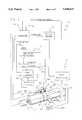
- FIG. 1is a schematic illustration, partly in perspective, of a programmable engraving system according to the present invention
- FIG. 2is a schematic illustration of a series of cells engraved in a printing cylinder
- FIGS. 3A-3Care time-correlated schematic illustrations of AC and video signals for controlling an engraving stylus and the engraving movement which results therefrom;
- FIG. 4is a flow chart illustrating the method of cell width control in accordance with the invention.
- FIG. 5is a graphical plot of the maximum cell depths resulting from video input signals ranging from 0 to 10 volts;
- FIG. 6is a schematic illustration of a video frame including a highlight cell
- FIG. 7is a flow chart of a cell width measuring algorithm
- FIGS. 8A and 8Btaken together, show a flow chart of another measuring algorithm.
- FIG. 1there is illustrated a gravure printing cylinder 10 mounted for rotation by a drive motor 12 and engraving by an engraving stylus 20.
- stylus 20moves engravingly toward and away from printing cylinder 10 to produce a series of cells arranged along a track 30.
- a lead screw motor 14rotates a leadscrew 56 to cause movement of stylus 20 in a direction parallel to the axis of cylinder 10. If lead screw motor 14 moves continuously, then track 30 will have a helical configuration. Intermittent energization of motor 14 produces a series of spaced circular tracks 30.
- Stylus 20is driven into engraving contact with print cylinder 10 by an electromagnetic driver 61 operating in response to a drive control signal on line 60.
- Electromagnetic driver 61may be configured as generally disclosed in Buechler U.S. Pat. No. 4,450,486.
- the signal on line 60has an AC component, a video component and a white offset component appropriate for producing an engraving action as hereinafter described.
- the AC componentis derived from an AC input signal generated by a clock 47 and applied to a computer 34.
- the AC input signalis multiplied by a multiplication factor Ka as described in detail in Ser. No. 08/022,127.
- Computer 34generates the video component by calculating another multiplication factor Kd and multiplying it against a video input signal.
- the white offsetis derived from an offset signal WD.
- Computer 34generates the parameters Ka, Kd and WD by solving a set of three equations as described below.
- a control panel or keyboard 32is provided in order enable entry of values for six constants appearing in the three equations. These constants are black cell width, BW, highlight cell width, HW, channel width, CW, the video voltage, Vh, corresponding to HW, HW, a stylus constant, Ks, and the black cell voltage, Vmax.
- a shoe offset, Smay also be entered if desired.
- the AC component of the signal on line 60causes stylus 20 to oscillate in a sinusoidal manner relative to printing cylinder 10 with a wavelength dependent upon the surface speed of the cylinder.
- the rotational speed of drive motor 12must be adjusted so as to produce an engraving track 30 having an odd number of half wavelengths during a full engraving rotation.
- Computer 34transmits a lead screw control signal to lead screw motor 14 via a line 24. This signal is adjusted so as to cause lead screw motor 14 to advance stylus 20 an axial distance equal to one-half of a black cell width plus one-half of a connecting channel width, plus one separating wall width during each complete rotation of the printing cylinder 10.
- computer 34may be programmed properly and may initially produce correct cell widths, gain changes in analog components or mechanical changes in the positioning of the shoe which supports stylus 20 may require incorporation of an adjustable correction term in the algorithm employed for calculation of Ka, Kd and WD.
- a videoing means or imagessuch as video camera 46, which is focussed on track 30.
- Camera 46views a portion of track 30 which is illuminated by a strobed lamp 58 and provides frames of video feedback information to a video processor 41.
- Strobe signals for lamp 58are provided at the correct frequency and phase by a cell counter 42 on line 55.
- the strobed lamp 58is integral with the video camera 46 so that the strobe flashes through a lens (not shown) of video camera 46.
- the video camera 46may have an auto-focus camera or attachment 202 for enabling it to focus on any size print cylinder 10.
- the video processor 41is capable of controlling the autofocus feature so that if, for example, the printing cylinder 10 is changed to a printing cylinder having a different radius.
- the video processor 41includes conventional circuitry to ensure that the image is in focus.
- Cell counter 42counts pulses generated by a clock 47 at four times the AC frequency. At this frequency a clock pulse is generated each quarter wavelength of engraving stylus oscillation.
- FIG. 2The geometrical configurations of typical black cells, connecting channels for black cells, highlight cells and separating walls are illustrated in FIG. 2. That figure depicts a series of wide, deep black cells 70 and a series of shallower and narrower highlight cells 76.
- the illustrated cellscomprise portions of three side-by-side engraving tracks 30.
- Black cells 70have a maximum width BW.
- the control signal for the stylusis adjusted so as to produce connecting channels 72 between successively engraved black cells 70.
- Channels 72have a width CW
- highlight cells 76have a width HW.
- the scalloped edges of the cells 70result from the vertically oscillating cutting action of stylus 20 during rotational movement of printing cylinder 10 thereunder.
- a series of successively engraved black cells 70may be separated by a wall 74 from a series of successively engraved cells 70 (also illustrated as being black cells) in an adjacent engraving track 30.
- a series of cells configured as illustrated in FIG. 2will print a graphic pattern defining a diagonally extending screen.
- the tangent of the screen angleis the ratio of the black cell width to the wavelength of the stylus cutting motion.
- the cutting wavelengthis a function of the surface speed of the printing cylinder 10 and the oscillation frequency of stylus 20.
- the screen anglemay be adjusted by adjusting the rotational speed of drive motor 12, but such adjustment must be made in incremental steps so as to maintain an odd number of half wavelengths around the circumference of the printing cylinder.
- the screen anglemay be adjusted by adjusting the black cell width and the operating speed of leadscrew motor 14.
- the driving signals for stylus 20 and the resulting vertical movement of the stylus 20are illustrated in FIGS. 3A-3C.
- the driving signal(FIG. 3A) is obtained by adding an AC signal 80 (FIG. 3A) to a video signal 82 (FIG. 3B).
- the illustrated video signal 82has, by way of example, a white video level 86, a black video level 88 and a highlight video level 90.
- the video signal and the AC signalare combined with an offset such that the stylus is raised out of contact with the cylinder surface during the entire time that video signal 82 has a white level 86.
- the minimum white elevationis WD.
- a set of predetermined setup parameters(BW, HW, CW, Vh, Ks and Vmax) may be inputted into control panel 32.
- These predetermined setup parametersgenerally correspond to the desired dimensions of, for example, either the highlight cell 76 or cell 70.
- These parametersare received by computer 34 which, in turn, generates a plurality of energizing signals (Ka, WD and Kd) in response thereto.
- the input signalscontrol the depth of stylus 20 at any instant in time.
- the computer 34determines the depth of stylus 20 by using the following equations.
- V(t)video voltage at input (function of time)
- the depths BD, CD and HDare respectively equal to Ks * BW, Ks * CW and Ks * HW, where Ks is a stylus constant given by the equation:
- equations (1)-(3)can be rearranged to produce:
- Eis an error which is used to correct the solution for observed errors in HW.
- Equations (4)-(6)may be solved in sequence.
- the value of Kv obtained from the solution of Equation (4)may be used in the solutions of Equations (5) and (6), and the value of WD obtained from Equation (5) may be used in Equation (6).
- Computer 34proceeds in this fashion to calculate Kv, WD and Ka.
- the screen angle (SA) and the wavelength (WL) of the stylus cutting motionmay be used as setup parameters.
- BWmay calculated from the equation:
- an additional predetermined setup parameter Smay be supplied to computer 34. If this parameter is provided, it is treated as a depth offset which is multiplied by Ks and added to BW, CW and HW prior to performing the above outlined solution.
- the maximum cell depthis seen to be directly proportional to the video input signal.
- a maximum 10 volt video input signalproduces the maximum cell depth BD required for engraving a black cell.
- the highlight depth HDis 25% of BD.
- the Figurealso reflects a setting of 3 volts for Kh. Under those conditions a video signal having an amplitude equal to 30% of a "black" video signal produces a cut having a depth which is only 25% of the black cell depth. As a result the maximum cell depth goes to zero for a video input of about 0.7 volts.
- the cutting stylusremains out of contact with the printing cylinder.
- the stylusis retracted from the engraving cylinder by a minimum distance WD, which is the white offset.
- the predetermined setup parameters BW, HW, Vh, Ks, and Vmax and their associated energizing signals Kd, WD and Kamay be desirable to adjust the predetermined setup parameters BW, HW, Vh, Ks, and Vmax and their associated energizing signals Kd, WD and Ka to reflect differences between the predetermined setup parameters and an actual measurement of a portion of an engraved area (FIG. 2).
- Thisfacilitates providing a closed-looped system which can be self-adjusting and self-monitoring.
- the computer 34can adjust the predetermined setup parameters and corresponding energizing signals Ka, WD and Kd in response to the error value E.
- camera 46may be adjusted for viewing a precisely determined position of track 30. It is to be noted that an individual cell is strobed while the engraver is engraving. For this purpose. stylus 20 is activated to engrave a test track at one end of cylinder 10. Although it is possible that an operator could view a monitor or display (not shown) and manipulate a cursor control knob (not shown) on the above-mentioned keyboard, computer 34 is capable of automatically strobing a flash and capturing an image on the video camera 46. The video processor gets the new image and measures the width of the strobed cell and its associated channel. This information is sent to computer 34 as cell size feedback information.
- computer 34Since there is a distance between the stylus 20 and the camera pickup 46, computer 34 has to save a cell position distance count between camera 46 and stylus 20.
- the computeruses this position offset count to time strobes on line 55 for imaging specific cells known to have been engraved at particular points in time.
- FIG. 4illustrates the overall process involved in controlled engraving and error correction system according to one embodiment of the present invention.
- the processbegins at an entry point indicated by the reference numeral 100.
- the first stepis the entry of the setup parameters BW, HW, Vmax, Vh and Ks (Block 102). These parameters may be read from a disk file or entered into a keyboard by an operator.
- the predetermined setup parametersmay be obtained by visual observation of cells in a manually controlled sample track which is cut at one end of printing cylinder 10.
- the predetermined setup parametersare stored in computer 34 for setup control.
- Computer 34sets the value of the error term, E, equal to a zero (Block 104) and proceeds to calculate the engraving drive parameters Kd, WD and Ka using equations (4)-(6) above (Block 106). This puts the system in readiness to commence engraving.
- Computer 34Once the engraving drive parameters are available, computer 34 generates the energizing or control signals which cause video data to be read pixel data from an appropriate data file (Block 108). Other control signals activate drive motor 12, leadscrew motor 14 and workhead 16, and engraving begins (Block 110). Computer 34 then begins checking the progress of the engraving job (Point 112). The system exits at Point 114 when the job is done.
- the error value Emay be determined by using one predetermined setup parameter, namely, Vh.
- the error correction systemcalculates error value E by comparing the most frequently occurring value of Vh for a plurality of cells that have actually been cut to a value of Vh which is determined by taking an actual measurement of a preselected cell 606 (FIG. 7) which has been cut.
- a most frequently occurring value of Vhis assumed to be the system setup parameter or the predetermined setup parameters. Therefore computer 34 maintains a record of the frequency of occurrence of different values of Vh (Block 116) and compares the set value of Vh against the value of Vh which is found to be most frequently occurring.
- Block 124This block involves a strobing of lamp 58 which causes camera 46 to generate a frame of video information.
- Video processor 41is also strobed to measure the width of a highlight cell which appears in the video frame and which is known to have been engraved in response to a video voltage Vh.
- the error term, Eis set equal to the difference between the actual measured value HW and the current setting of HW.
- the systemthen proceeds back to Block 127 where the predetermined setup parameters, such as Kd, WD and Ka, are recalculated in computer 34 using the new value of E. This has the effect of eliminating or reducing the error value E.
- the systemthen returns to block 108.
- Video camera 46is mounted on a frame 57 supported by leadscrew 56. Camera 46 is adjustable relative to frame 57 so as to generate frames of video information which are centered upon track 30. Preferably, camera 46 comprises a CCD array which produce a new frame of video information with each flash of lamp 58.
- camera 46be adjusted for viewing a precisely determined portion of track 30.
- stylus 20is activated to engrave a test track at one end of cylinder 10.
- Computer 34saves this position count and uses it to time the strobes on line 55 for imaging specific cells known to have been engraved at particular points in time.
- FIG. 6illustrates a typical frame of video information 600 including a highlighted cell 606 which was engraved PC clock counts prior generation of the strobe which produced the frame 600.
- Frame 600comprises a series of horizontal lines which are too numerous for illustration. Representative horizontal video lines are indicated by the reference numerals 602. These lines are a subsampling of the cell image captured by the strobe. The actual cell size dimensions are measured from these lines.
- Video processor 41processes lines 602 sequentially from top to bottom.
- the video informationgoes through localized thresholding (not shown). Pixels which are lighter than the threshold are deemed to be white, whereas pixels which are darker than the threshold are deemed to be black.
- the threshold amountsare set at a preselected gray scale.
- FIG. 6illustrates black/white transitions by symbols denoted by the reference numeral 610, whereas white/black transitions are denoted by symbols indicated by the reference numeral 611. This establishes a series of boundary lines as illustrated in FIG. 6 by reference numerals 604, 605, 606, 607, 608 and 609. These boundary lines define a white region 650.
- Video processor 41recognizes the white region 650 by a black/white transition 610 followed by a white/black transition 611. For each such transition pair, video processor 41 establishes a first linked list. If the programming is performed in the C language, for example, then such a linked list may be represented by an entity known as a structure. Each such linked list includes the X coordinates of the left and right boundaries of the white region indicated by the transition pair. The linked lists for each scan line 602 are associated with the linked lists of the preceding scan line by comparison of the boundary points.
- the video processorknows that highlight cell 606 is present.
- the video processorcompares the left boundary of the third linked list with the right boundary of the second linked list to determine the width of the highlight cell 606.
- the highlight widthis calculated for each scan line 602 and compared with the highlight width calculated for the preceding scan line.
- video processor 41saves the larger value. The process continues until the intermediate black region disappears (at 602b) and the two legs of white region 650 merge. At this point the measurement ceases and the processor saves the observed maximum value of HW.
- Video processor 41passes this value of HW to computer 34.
- the computer 34associates the reported value of HW with the specific engraving command, which was sent to stylus 20 PC clock counts earlier than the strobe which produced the video frame. For this purpose computer 34 samples the video information which is supplied to multiplier 38.
- FIG. 7illustrates the above outlined measuring process in flow chart form.
- HW measurementbegins at a start point 136 and proceeds to a scanning step at block 138.
- frame grabbing or scanningis initiated by a strobe signal on line 55.
- the cylindercould be stationary (i.e., not revolving during) the videoing, measuring and error correction process.
- the system and method for measuringmay be used independently to provide means for measuring portions of actual cuts in cylinder 10.
- the system and method of measuring per secould be used to measure the actual measurements for display on a monitor (not shown) so that subsequent manual adjustments, for example, can be made to correct for any errors.
- the video processorchecks the line number at point 140. If the bottom of the frame has been reached, then there is an exit at point 142. Assuming that the frame bottom has not been reached, the program proceeds to block 144 where it establishes transition points 610, 611. Then the program obtains the white ranges at block 146 for use in the above-described linked lists. Next the program looks for a split at point 148. If a split is noted, then the two resulting linked lists are tagged at block 152 and a flag is set at block 154.
- the programchecks the state of the flag at point 156 and jumps down to block 164 for a negative result. This means that the top of highlight cell 606 has not yet been reached and there is no need to measure a cell width. Consequently, the program simply increments the line number at block 164 and returns back to point 140.
- the programchecks for a merge at point 158. If a merge is noted, then the program exits from the measurement routine. If a merge has not yet occurred, then the program checks the separation distance between the two legs of the white region 650. This distance is compared at point 160 against previously saved separation distances. If the new separation distance is greater than any previously saved distance, then HW is set equal to that distance. Referring again to FIG. 6, the first separation distance is the distance between points 611d and 610d. This distance keeps increasing until the program reaches points 611a and 610a. At that point the separation distance is maximum, and no further adjustments of HW are made.
- the video processor 41then feeds the measured value of HW back to computer 34 and it is compared to the most frequently occurring value of HW. If the difference is below a predetermined threshold or zero, then no adjustment is made to the predetermined setup parameters. If on the other hand, there is a difference between the HW measured and the most frequently occurring value of HW, then computer 34 adjusts the predetermined setup parameters until the engraver is cutting cells that fall within the predetermined setup.
- this inventioncomprises a method for measuring a portion 67 (FIG. 2) of an engraved area 69 on the cylinder 10 during rotation of the cylinder 10 or while the cylinder 10 is stationary.
- the methoduses video processor 41, videocamera 46 and strobe 58.
- the methodcomprises the steps of videoing the portion 67 of the engraved area 69 and generating a video image (such as the image shown in FIG. 6) corresponding thereto. These steps are effected by using the video processor 41 to process the video image data in order to determine the actual measurements of the portion which was videoed.
- FIG. 8shows another embodiment of the invention wherein the cell width BW, channel width CW, highlight width HW, and error value E are measured and determined using a similar technique.
- video processor 41determines the existence of the white region 650 by the black/white transition 610 followed by a white/black transition 611. The cell which was actually measured and strobed is assumed to be generally located in the center of the scan frame 600.
- the video processor 41begins a filling in process whereby it starts from a location somewhere within cell 606 and begins filling in memory locations associated or corresponding to cell 606 with gray scale values.
- Video processorfirst selects a black pixel, which is preferably centrally located within cell 606.
- Video processor 41then "fills" the selected pixel and all adjacent black pixels with a half tone or gray value which is somewhere between the white and black values which are conventionally stored in memory.
- video processor 41is measuring a highlight cell 70 (FIG. 2) and 606 (FIG. 6) which was strobed by video camera 46 and strobed lamp 58. As video processor 41 completes filling in cell 606, it conventionally stores all black/white transition points and white/black transition points in memory.
- transition pointsare located. These transition points generally correspond to the boundary lines or wall 606 (FIG. 6).
- the video processor 41then examines these transition points and determines, by each horizontal scan line 602, the leftmost and rightmost (as viewed in FIG. 6) transition points. These transition points correspond to the points, like points 615 and 617 around the boundary of cell 606.
- Video processor 41determines that this is a highlight cell because no half tones reached the top 621 or bottom 623 of the scan frame 600.
- channel width, CW, of channel 72 (FIG. 2) and cell width, BW, of cell 70are determined in a similar manner by video processor 41.
- the minimum distance determined by video processor 41would correspond to the channel width, CW. If the video processor 41 determines that the minimum distance is below zero, then there is no channel and it is assumed a highlight cell, like cell 606 in FIG. 6, is being measured. As with the maximum distance, the minimum distance between black/white and white/black transitions which lie on the same line 602 are scaled to the magnification and pixel sizes of video camera 46 (FIG. 1).
- the highlight width, HWhas been measured, it is fed back to computer 34 and the error value E is determined.
- Computer 34receives the highlight width HW and compares it to the HW corresponding to the predetermined set up parameters. If the error value E is below the predetermined threshold or zero, then no error adjustment is made to the predetermined setup parameters because the engraver is engraving highlight cells 76 (FIG. 2) having actual measurements which generally correspond to desired measurements prescribed by the predetermined setup parameters.
- computer 34determines that the highlight cell 76 (FIG. 2) actually being engraved has dimensions which are different from the dimensions corresponding to the predetermined setup parameters. As mentioned earlier herein, computer 34 may use the most frequently occurring value of HW to determine the error value E. In this case, the error value E would represent the difference between the HW and the most frequently occurring value of HW which has been stored in memory for a plurality of highlight cells 76 which have been strobed and measured.
- computer 34causes several measurements of the same size highlight cell 76 to be taken to verify the error value E.
- Computer 34then adjusts one or more of the predetermined setup parameters BW, HW, CW, Vh, Ks, Vmax and S to account for the error value E.
- FIG. 8illustrates the measuring process according to this embodiment of the invention.
- the measuring processbegins at start block 170 and proceeds to scan a frame of data at block 172. This is similar to the measuring process described above with respect to FIG. 7. After the scan frame of data is captured, the data is broken down into a plurality of localized sectors at block 174. Using a plurality of smaller localized sectors in this embodiment of the invention permits the video processor 41 and computer 34 to process data faster. Threshold points are determined for each localized sector. Thresholding is performed with each sector so that white/black and black/white transition points within that sector can be located. This process continues until all the black/white and white/black transition points are found for each sector in the scan frame and, ultimately, for the entire cell being measured at block 176.
- the video processor 41begins the memory fill at block 180 by filling in all the black cavities for the cell being measured. Thereafter, the maximum and minimum transition points on a particular scan line are identified by video processor 41 at block 182.
- the video processor 41checks to determine if the memory fill in has reached the sides 625 and 627 (FIG. 6). If it has reached sides 625 and 627, then video processor 41 determines that no cell or channel is being measured (block 186). If it has not reached sides 625 and 627, then video processor 41 determines if the fill in has reached top 621 or bottom 623 at point 188. If the top 621 or bottom 623 has been reached, video processor 41 calculates the channel width CW and cell width BW at block 190 using the maximum and minimum values determined at block 186. If the top 621 or bottom 623 has not been reached, then video processor determines the highlight cell width HW at block 192. After all the measurements have been determined, video processor exits at point 194, whereupon an error value E is determined by computer 34 in the manner described earlier herein.
- this inventionprovides an error detection or error detector 101 and correction system suitable for providing a closed-loop system for engraving highlight cells 76 (FIG. 2), cells 70 and channels 72 in a gravure engraver.
- the error detection and correction systempermit an error value E to be determined and fed back to computer 34, whereupon feedback adjustments can be made to one or more of the predetermined setup parameters. This permits the gravure engraver to engrave actual cuts, cells and channels in accordance with predetermined setup parameters.
- this systemmay be used during initial setup or during the normal operation of the gravure engraver.
- the system and method described hereincan provide "real time” display of the actual measurement and "real time” correction for any error value E.
Landscapes
- Engineering & Computer Science (AREA)
- Manufacturing & Machinery (AREA)
- Multimedia (AREA)
- Signal Processing (AREA)
- Human Computer Interaction (AREA)
- Mechanical Engineering (AREA)
- General Engineering & Computer Science (AREA)
- Physics & Mathematics (AREA)
- General Physics & Mathematics (AREA)
- Automation & Control Theory (AREA)
- Health & Medical Sciences (AREA)
- Biomedical Technology (AREA)
- General Health & Medical Sciences (AREA)
- Manufacture Or Reproduction Of Printing Formes (AREA)
Abstract
Description
D(t)=Ka * A * (sin (ω * t)-1)-WD+Kd * V(t)
BD=Kv * Vmax-WD (1)
CD=Ka * A-WD+Kv * Vmax (2)
HD=Kv * Vh-WD (3)
Ks=1 / (2 * TAN (tip / 2)).
Kv=Ks * (BW-HW+E) / (Vmax-Vh) (4)
WD=Kv * Vmax-Ks * BW (5)
Ka=(Ks * CW+WD-Kv * Vmax) / A (6)
BW=WL * tan (SA)
HW=(Kd * Vh-WD) / Ks.
Claims (53)
Priority Applications (26)
| Application Number | Priority Date | Filing Date | Title |
|---|---|---|---|
| US08/038,679US5438422A (en) | 1993-02-25 | 1993-03-26 | Error detection apparatus and method for use with engravers |
| US08/125,938US5440398A (en) | 1993-02-25 | 1993-09-23 | Error detection apparatus and method for use with engravers |
| CH01437/97ACH688472A5 (en) | 1993-02-25 | 1994-02-22 | Engraving and engraving to its execution. |
| RU95121945ARU2130384C1 (en) | 1993-02-25 | 1994-02-22 | Device for detection of errors and method for engraving |
| CH03250/94ACH688471A5 (en) | 1993-02-25 | 1994-02-22 | Engraving and method for its operation |
| JP6519214AJPH08507722A (en) | 1993-02-25 | 1994-02-22 | Error detection device and method for engraving machine |
| DE4447756ADE4447756C2 (en) | 1993-02-25 | 1994-02-22 | Measuring engraved area on printing cylinder in engraver |
| PCT/US1994/001871WO1994019900A1 (en) | 1993-02-25 | 1994-02-22 | Error detection apparatus and method for engravers |
| DE4491078ADE4491078C2 (en) | 1993-02-25 | 1994-02-22 | Measuring engraved area on printing cylinder in engraver |
| CNB941912868ACN1154336C (en) | 1993-02-25 | 1994-02-22 | Error detection apparatus and method for engravers |
| DE4491078TDE4491078T1 (en) | 1993-02-25 | 1994-02-22 | Fault detection device and method for engraving machines |
| BR9405739ABR9405739A (en) | 1993-02-25 | 1994-02-22 | Process and system for measuring a part of an area recorded on a cylinder in a gravoder recorder error correction and recorder control system |
| US08/394,717US5825503A (en) | 1993-02-25 | 1995-02-27 | Engraving apparatus and method for adjusting a worn stylus using a midtone correction |
| US08/394,722US5617217A (en) | 1993-02-25 | 1995-02-27 | Engraving method and apparatus for generating engraving drive signals for engraving engraved areas of accurately controlled size in the surface of a workpiece using coefficient values and associated set up parameter values |
| US08/415,638US5737090A (en) | 1993-02-25 | 1995-04-03 | System and method for focusing, imaging and measuring areas on a workpiece engraved by an engraver |
| US08/434,592US5663803A (en) | 1993-02-25 | 1995-05-04 | Engraving method and apparatus for engraving areas using a shaping signal |
| US08/476,093US5737091A (en) | 1993-02-25 | 1995-06-07 | Error detection apparatus and method for use with engravers |
| US08/529,557US5691818A (en) | 1993-02-25 | 1995-09-18 | System and method for enhancing edges and the like for engraving |
| US08/642,610US5831746A (en) | 1993-02-25 | 1996-05-03 | Engraved area volume measurement system and method using pixel data |
| US08/744,184US5867280A (en) | 1993-02-25 | 1996-11-05 | Engraver with automatic tool changer |
| US08/887,179US5894354A (en) | 1993-02-25 | 1997-07-02 | Method and apparatus for engraving patterns with and without image feedback |
| US08/887,157US5886792A (en) | 1993-02-25 | 1997-07-02 | Engraver for defining/generating edges or edge signals |
| US09/039,575US6614558B1 (en) | 1993-02-25 | 1998-03-16 | Engraver and method for focusing and measuring areas on a workpiece engraved by the engraver |
| US09/055,518US6362899B1 (en) | 1993-02-25 | 1998-04-06 | Error detection apparatus and method for use with engravers |
| US09/083,816US6348979B1 (en) | 1993-02-25 | 1998-05-22 | Engraving system and method comprising improved imaging |
| US09/778,506US20020135811A1 (en) | 1993-02-25 | 2001-02-07 | Error detection apparatus and method for use with engravers |
Applications Claiming Priority (2)
| Application Number | Priority Date | Filing Date | Title |
|---|---|---|---|
| US08/022,127US5424845A (en) | 1993-02-25 | 1993-02-25 | Apparatus and method for engraving a gravure printing cylinder |
| US08/038,679US5438422A (en) | 1993-02-25 | 1993-03-26 | Error detection apparatus and method for use with engravers |
Related Parent Applications (2)
| Application Number | Title | Priority Date | Filing Date |
|---|---|---|---|
| US08/022,127Continuation-In-PartUS5424845A (en) | 1993-02-25 | 1993-02-25 | Apparatus and method for engraving a gravure printing cylinder |
| US08/242,012Continuation-In-PartUS5492057A (en) | 1993-02-25 | 1994-05-12 | Method and apparatus for positioning at least one engraving head |
Related Child Applications (4)
| Application Number | Title | Priority Date | Filing Date |
|---|---|---|---|
| US08/125,938Continuation-In-PartUS5440398A (en) | 1993-02-25 | 1993-09-23 | Error detection apparatus and method for use with engravers |
| US08/394,722Continuation-In-PartUS5617217A (en) | 1993-02-25 | 1995-02-27 | Engraving method and apparatus for generating engraving drive signals for engraving engraved areas of accurately controlled size in the surface of a workpiece using coefficient values and associated set up parameter values |
| US08/415,638Continuation-In-PartUS5737090A (en) | 1993-02-25 | 1995-04-03 | System and method for focusing, imaging and measuring areas on a workpiece engraved by an engraver |
| US08/434,592ContinuationUS5663803A (en) | 1993-02-25 | 1995-05-04 | Engraving method and apparatus for engraving areas using a shaping signal |
Publications (1)
| Publication Number | Publication Date |
|---|---|
| US5438422Atrue US5438422A (en) | 1995-08-01 |
Family
ID=46247884
Family Applications (1)
| Application Number | Title | Priority Date | Filing Date |
|---|---|---|---|
| US08/038,679Expired - LifetimeUS5438422A (en) | 1993-02-25 | 1993-03-26 | Error detection apparatus and method for use with engravers |
Country Status (1)
| Country | Link |
|---|---|
| US (1) | US5438422A (en) |
Cited By (35)
| Publication number | Priority date | Publication date | Assignee | Title |
|---|---|---|---|---|
| US5492057A (en)* | 1994-05-12 | 1996-02-20 | Ohio Electronic Engravers, Inc. | Method and apparatus for positioning at least one engraving head |
| WO1996031349A1 (en)* | 1995-04-03 | 1996-10-10 | Ohio Electronic Engravers, Inc. | Engraving error detection apparatus and method |
| WO1996033870A1 (en)* | 1995-04-27 | 1996-10-31 | Ohio Electronic Engravers, Inc. | Method of engraving a printing surface |
| WO1996034746A1 (en)* | 1995-05-04 | 1996-11-07 | Ohio Electronic Engravers, Inc. | Engraving method and apparatus |
| US5652659A (en)* | 1995-10-09 | 1997-07-29 | Ohio Electronic Engravers, Inc. | System and method for measuring run-out and other characteristics of a workpiece mounted on an engraver |
| US5663801A (en)* | 1993-09-22 | 1997-09-02 | Dainippon Screen Mfg. Co., Ltd. | Control circuit for controlling stylus overshoot in an engraving machine used for engraving gravure cylinders and method for same |
| US5671064A (en)* | 1994-11-04 | 1997-09-23 | Ohio Electronic Engravers, Inc. | Method and apparatus for engraving using a magnetostrictive actuator |
| US5675420A (en)* | 1995-01-23 | 1997-10-07 | Ohio Electronic Engravers, Inc. | Intaglio engraving method and apparatus |
| US5737091A (en)* | 1993-02-25 | 1998-04-07 | Ohio Electronics Engravers, Inc. | Error detection apparatus and method for use with engravers |
| US5808748A (en)* | 1993-02-25 | 1998-09-15 | Ohio Electronic Engravers, Inc. | Method and system for generalizing an engraving drive signal in response to an engraving system |
| US5808749A (en)* | 1993-02-25 | 1998-09-15 | Ohio Electronic Engravers, Inc. | Engraving system and engraving signal generator for engraving workpieces |
| US5818605A (en)* | 1996-08-19 | 1998-10-06 | R.R. Donnelley & Sons Company | Method and apparatus for high resolution sensing of engraving stylus movement |
| US5816756A (en)* | 1995-05-02 | 1998-10-06 | Mdc Max Datwyler Bleienbach Ag | Device for engraving intaglio cylinders |
| US5828464A (en)* | 1992-10-28 | 1998-10-27 | Dainippon Screen Mfg. Co. Ltd. | Electromechanical rotogravure stylus automatic calibrator |
| US5831745A (en)* | 1995-01-19 | 1998-11-03 | Dainippon Screen Mfg. Co., Ltd. | Gravure engraving system using two signals out of phase with each other for engraving a plurality of cells on a surface of a gravure cylinder |
| WO1999007554A1 (en)* | 1997-08-08 | 1999-02-18 | Heidelberger Druckmaschinen Ag | Method for positioning engraving organs |
| US5894354A (en)* | 1993-02-25 | 1999-04-13 | Ohio Electronic Engravers, Inc. | Method and apparatus for engraving patterns with and without image feedback |
| WO1999036265A1 (en)* | 1998-01-16 | 1999-07-22 | Heidelberger Druckmaschinen Ag | Method for calibrating an engraving amplifier |
| WO1999036264A1 (en)* | 1998-01-16 | 1999-07-22 | Heidelberger Druckmaschinen Ag | Mid tone correction method |
| US5947020A (en)* | 1997-12-05 | 1999-09-07 | Ohio Electronic Engravers, Inc. | System and method for engraving a plurality of engraved areas defining different screens |
| WO1999061247A1 (en)* | 1998-05-22 | 1999-12-02 | Ohio Electronic Engravers, Inc. | Engraving system and method comprising improved imaging |
| US6025921A (en)* | 1995-01-23 | 2000-02-15 | Ohio Electronics Engravers, Inc. | Method and apparatus for engraving a mixed pattern |
| US6048446A (en)* | 1997-10-24 | 2000-04-11 | R.R. Donnelley & Sons Company | Methods and apparatuses for engraving gravure cylinders |
| US6362899B1 (en) | 1993-02-25 | 2002-03-26 | Mdc Max Daetwyler Ag | Error detection apparatus and method for use with engravers |
| US6430462B1 (en)* | 1997-06-02 | 2002-08-06 | Heidelberger Druckmaschinen Ag | Signal processing method |
| US6433890B1 (en) | 1998-09-24 | 2002-08-13 | Mdc Max Daetwyler Ag | System and method for improving printing of a leading edge of an image in a gravure printing process |
| US6540453B1 (en)* | 1998-04-03 | 2003-04-01 | Hall Gravure Systems Gmbh | Method for positioning engraving members |
| DE10144198A1 (en)* | 2001-09-08 | 2003-04-03 | Hell Gravure Systems Gmbh | Method for positioning engraving members for use in engraving a print cylinder, using video cameras for determination of the difference between actual and design positions so that the difference can be compensated |
| US6563605B1 (en) | 1998-02-20 | 2003-05-13 | R. R. Donnelley & Sons Company | Methods of determining gravure cylinder parameters |
| US6737776B1 (en)* | 2003-03-28 | 2004-05-18 | The United States Of America As Represented By The Secretary Of The Navy | Hybrid linear motor |
| US7085018B1 (en)* | 1999-10-19 | 2006-08-01 | Hell Gravure Systems Gmbh | Method for engraving printing cylinders |
| US20080141886A1 (en)* | 2006-10-23 | 2008-06-19 | Fischer & Krecke Gmbh & Co. Kg | Method of adjusting a roller in a rotary printing press |
| US20080285086A1 (en)* | 2007-05-18 | 2008-11-20 | Max Daetwyler Corp. | System and method for an improved engraving of gravure cylinders |
| DE102006060464C5 (en)* | 2006-12-19 | 2013-12-24 | Bobst Bielefeld Gmbh | Method of adjusting a roll in a rotary printing machine |
| US9254637B2 (en) | 2013-09-27 | 2016-02-09 | Ohio Gravure Technologies, Inc. | Real-time virtual proofing system and method for gravure engraver |
Citations (36)
| Publication number | Priority date | Publication date | Assignee | Title |
|---|---|---|---|---|
| US2493628A (en)* | 1945-12-15 | 1950-01-03 | Earle L Harley | Optical means for registering printing surfaces |
| US2777058A (en)* | 1951-09-28 | 1957-01-08 | Fairchild Camera Instr Co | Video-signal tone-adjusting network |
| US2874479A (en)* | 1955-07-15 | 1959-02-24 | Fairchild Camera Instr Co | Engraving machine stylus index |
| US2943564A (en)* | 1957-12-24 | 1960-07-05 | Ibm | Printed data storage interpreter |
| US3612753A (en)* | 1969-04-23 | 1971-10-12 | Ventures Res & Dev | Self-adaptive system for the reproduction of color |
| US3652992A (en)* | 1968-11-02 | 1972-03-28 | Hell Rudolf Dr Ing | Method and apparatus for quantizing a character or test pattern preferably for the purpose of gaining control data for electronic photo composition |
| US3876829A (en)* | 1973-04-20 | 1975-04-08 | Massachusetts Inst Technology | Electro-optical communication of visual images |
| US3904816A (en)* | 1971-07-28 | 1975-09-09 | Hell Rudolf | Method for the dot-by-dot and line-by-line reproduction of picture originals |
| US3918348A (en)* | 1973-09-18 | 1975-11-11 | Cross Co | Adaptive control system |
| US3931570A (en)* | 1974-09-19 | 1976-01-06 | Gravure Research Institute, Inc. | Apparatus for measuring cell volume in a gravure printing surface |
| US3956583A (en)* | 1974-05-03 | 1976-05-11 | Crosfield Electronics Limited | Image reproduction systems providing reproduction at a finer pitch than input scanning |
| US4001495A (en)* | 1974-07-15 | 1977-01-04 | A. B. Dick Company | Devices for the copying of images by sequential sweeping |
| US4003311A (en)* | 1975-08-13 | 1977-01-18 | Bardin Karl D | Gravure printing method |
| US4012584A (en)* | 1974-01-30 | 1977-03-15 | Crosfield Electronics Limited | Apparatus for making a screen reproduction of an image |
| US4052739A (en)* | 1972-05-19 | 1977-10-04 | Matsushita Electric Industrial Co., Ltd. | Electronic engraving system |
| US4072928A (en)* | 1975-10-10 | 1978-02-07 | Sangamo Weston, Inc. | Industrial system for inspecting and identifying workpieces |
| US4075662A (en)* | 1975-06-13 | 1978-02-21 | Dr. -Ing. Rudolf Hell Gmbh | Method and system for compensating the non-linearities in a reproduction process |
| US4240118A (en)* | 1975-04-25 | 1980-12-16 | Dr. Ing. Rudolf Hell Gmbh | Method for electro-optically sensing, transmitting pictorial information |
| US4315285A (en)* | 1978-08-21 | 1982-02-09 | Dr.-Ing. Rudolf Hell Gmbh | Methods for converting a video signal into a black/white signal |
| US4342050A (en)* | 1980-09-29 | 1982-07-27 | Xerox Corporation | Beam intensity measurement system for raster scanners |
| US4363037A (en)* | 1976-08-07 | 1982-12-07 | Dr.-Ing. Rudolf Hell Gmbh | Apparatus and process for recording an image free of line structure |
| US4394693A (en)* | 1979-03-23 | 1983-07-19 | International Business Machines Corporation | System and method for generating enlarged or reduced images |
| US4437122A (en)* | 1981-09-12 | 1984-03-13 | Xerox Corporation | Low resolution raster images |
| US4451856A (en)* | 1979-07-11 | 1984-05-29 | Ohio Electronic Engravers, Inc. | Engraving and scanning apparatus |
| US4503468A (en)* | 1981-10-09 | 1985-03-05 | Northern Telecom Limited | Interactive viewgraph system |
| US4612584A (en)* | 1983-06-03 | 1986-09-16 | Gravure Research Institute, Inc. | Screen gravure engraving system for electromechanical engravers |
| US4683499A (en)* | 1985-01-11 | 1987-07-28 | Dainippon Screen Mfg. Co., Ltd. | Method for generating a pixel synchronizing signal in a picture input scanning apparatus and a reproduction record scanning apparatus and apparatus therefor |
| US4683500A (en)* | 1984-12-25 | 1987-07-28 | Dainippon Screen Mfg. Co., Ltd. | Method for reproducing picture image |
| US4691238A (en)* | 1982-10-21 | 1987-09-01 | Dainippon Screen Mfg. Co., Ltd. | Method and apparatus of storing image data into a memory in a layout scanner system |
| US4691229A (en)* | 1983-09-10 | 1987-09-01 | Dr. Ing. Rudolf Hell Gmbh | Apparatus for checking color pictures on a color monitor |
| US4700235A (en)* | 1983-11-14 | 1987-10-13 | Dr. Ing. Rudolf Hell Gmbh | Method and apparatus for producing half-tone printing forms with rotated screens on the basis of randomly selected screen threshold values |
| US4944593A (en)* | 1986-05-27 | 1990-07-31 | Dr. Ing. Rudolf Hell Gmbh | Volume-measuring method for surface depressions |
| US4972323A (en)* | 1986-12-23 | 1990-11-20 | Roger LeCren | Automatic engraving systems and method |
| US5029011A (en)* | 1990-04-13 | 1991-07-02 | Ohio Electronic Engravers, Inc. | Engraving apparatus with oscillatory movement of tool support shaft monitored and controlled to reduce drift and vibration |
| US5229861A (en)* | 1989-05-24 | 1993-07-20 | Dai Nippon Insatsu Kabushiki Kaisha | Electronic gravure engraving apparatus including photo tone and character/solid tone processing |
| US5293426A (en)* | 1990-05-25 | 1994-03-08 | R. R. Donnelley & Sons Company | Printing cylinder engraver calibration system and method |
- 1993
- 1993-03-26USUS08/038,679patent/US5438422A/ennot_activeExpired - Lifetime
Patent Citations (37)
| Publication number | Priority date | Publication date | Assignee | Title |
|---|---|---|---|---|
| US2493628A (en)* | 1945-12-15 | 1950-01-03 | Earle L Harley | Optical means for registering printing surfaces |
| US2777058A (en)* | 1951-09-28 | 1957-01-08 | Fairchild Camera Instr Co | Video-signal tone-adjusting network |
| US2874479A (en)* | 1955-07-15 | 1959-02-24 | Fairchild Camera Instr Co | Engraving machine stylus index |
| US2943564A (en)* | 1957-12-24 | 1960-07-05 | Ibm | Printed data storage interpreter |
| US3652992A (en)* | 1968-11-02 | 1972-03-28 | Hell Rudolf Dr Ing | Method and apparatus for quantizing a character or test pattern preferably for the purpose of gaining control data for electronic photo composition |
| US3612753A (en)* | 1969-04-23 | 1971-10-12 | Ventures Res & Dev | Self-adaptive system for the reproduction of color |
| US3904816A (en)* | 1971-07-28 | 1975-09-09 | Hell Rudolf | Method for the dot-by-dot and line-by-line reproduction of picture originals |
| US4052739A (en)* | 1972-05-19 | 1977-10-04 | Matsushita Electric Industrial Co., Ltd. | Electronic engraving system |
| US3876829A (en)* | 1973-04-20 | 1975-04-08 | Massachusetts Inst Technology | Electro-optical communication of visual images |
| US3918348A (en)* | 1973-09-18 | 1975-11-11 | Cross Co | Adaptive control system |
| US4012584A (en)* | 1974-01-30 | 1977-03-15 | Crosfield Electronics Limited | Apparatus for making a screen reproduction of an image |
| US3956583A (en)* | 1974-05-03 | 1976-05-11 | Crosfield Electronics Limited | Image reproduction systems providing reproduction at a finer pitch than input scanning |
| US4001495A (en)* | 1974-07-15 | 1977-01-04 | A. B. Dick Company | Devices for the copying of images by sequential sweeping |
| US3931570A (en)* | 1974-09-19 | 1976-01-06 | Gravure Research Institute, Inc. | Apparatus for measuring cell volume in a gravure printing surface |
| US4240118A (en)* | 1975-04-25 | 1980-12-16 | Dr. Ing. Rudolf Hell Gmbh | Method for electro-optically sensing, transmitting pictorial information |
| US4075662A (en)* | 1975-06-13 | 1978-02-21 | Dr. -Ing. Rudolf Hell Gmbh | Method and system for compensating the non-linearities in a reproduction process |
| US4003311A (en)* | 1975-08-13 | 1977-01-18 | Bardin Karl D | Gravure printing method |
| US4072928A (en)* | 1975-10-10 | 1978-02-07 | Sangamo Weston, Inc. | Industrial system for inspecting and identifying workpieces |
| US4363037A (en)* | 1976-08-07 | 1982-12-07 | Dr.-Ing. Rudolf Hell Gmbh | Apparatus and process for recording an image free of line structure |
| US4315285A (en)* | 1978-08-21 | 1982-02-09 | Dr.-Ing. Rudolf Hell Gmbh | Methods for converting a video signal into a black/white signal |
| US4394693A (en)* | 1979-03-23 | 1983-07-19 | International Business Machines Corporation | System and method for generating enlarged or reduced images |
| US4451856A (en)* | 1979-07-11 | 1984-05-29 | Ohio Electronic Engravers, Inc. | Engraving and scanning apparatus |
| US4342050A (en)* | 1980-09-29 | 1982-07-27 | Xerox Corporation | Beam intensity measurement system for raster scanners |
| US4437122A (en)* | 1981-09-12 | 1984-03-13 | Xerox Corporation | Low resolution raster images |
| US4437122B1 (en)* | 1981-09-12 | 1993-03-30 | Xerox Corp | |
| US4503468A (en)* | 1981-10-09 | 1985-03-05 | Northern Telecom Limited | Interactive viewgraph system |
| US4691238A (en)* | 1982-10-21 | 1987-09-01 | Dainippon Screen Mfg. Co., Ltd. | Method and apparatus of storing image data into a memory in a layout scanner system |
| US4612584A (en)* | 1983-06-03 | 1986-09-16 | Gravure Research Institute, Inc. | Screen gravure engraving system for electromechanical engravers |
| US4691229A (en)* | 1983-09-10 | 1987-09-01 | Dr. Ing. Rudolf Hell Gmbh | Apparatus for checking color pictures on a color monitor |
| US4700235A (en)* | 1983-11-14 | 1987-10-13 | Dr. Ing. Rudolf Hell Gmbh | Method and apparatus for producing half-tone printing forms with rotated screens on the basis of randomly selected screen threshold values |
| US4683500A (en)* | 1984-12-25 | 1987-07-28 | Dainippon Screen Mfg. Co., Ltd. | Method for reproducing picture image |
| US4683499A (en)* | 1985-01-11 | 1987-07-28 | Dainippon Screen Mfg. Co., Ltd. | Method for generating a pixel synchronizing signal in a picture input scanning apparatus and a reproduction record scanning apparatus and apparatus therefor |
| US4944593A (en)* | 1986-05-27 | 1990-07-31 | Dr. Ing. Rudolf Hell Gmbh | Volume-measuring method for surface depressions |
| US4972323A (en)* | 1986-12-23 | 1990-11-20 | Roger LeCren | Automatic engraving systems and method |
| US5229861A (en)* | 1989-05-24 | 1993-07-20 | Dai Nippon Insatsu Kabushiki Kaisha | Electronic gravure engraving apparatus including photo tone and character/solid tone processing |
| US5029011A (en)* | 1990-04-13 | 1991-07-02 | Ohio Electronic Engravers, Inc. | Engraving apparatus with oscillatory movement of tool support shaft monitored and controlled to reduce drift and vibration |
| US5293426A (en)* | 1990-05-25 | 1994-03-08 | R. R. Donnelley & Sons Company | Printing cylinder engraver calibration system and method |
Non-Patent Citations (22)
| Title |
|---|
| "Datwyler", Max Daetwyler Corporation, 13420 West Reese Blvd., Huntersville, N.C. 28078, undated brochure. |
| "Numerical Analysis: A Practical Approach", Melvin J. Maron, p. 188 (no date). |
| "Numerical Recipes in C, The Art of Scientific Computing", William H. Press, Brian P. Flannery, Saul A. Teukolsky and William T. Vetterling; pp. 452-460 (1988). |
| "The Image Processing Handbook", John C. Russ, pp. 105-113, (1992). |
| "Twin-Pilot", Maschinenfabrik Kasper Walter GmbH & Co. KG, Plinganserstrasse 22, 8000 Munchen 70, German, undated, brochure. |
| Ahauser Tiefdruck Gravuren GmbH & Co., Engraving Tester ET2000 (Pamphlet, Date Unknown).* |
| Ahauser Tiefdruck-Gravuren GmbH & Co., Engraving Tester ET2000 (Pamphlet, Date Unknown). |
| Balcom, Basic Rotogravure (1988).* |
| Datwyler , Max Daetwyler Corporation, 13420 West Reese Blvd., Huntersville, N.C. 28078, undated brochure.* |
| Heimann GmbH, Check Master (Pamphlet, Date Unknown).* |
| Heimann GmbH, Check-Master (Pamphlet, Date Unknown). |
| Heimann GmbH, Drucktechnische Beratung Graphischer Handel (Pamphlet, Hamm, Germany, 1984).* |
| Heimann GmbH, Drucktechnische Beratung-Graphischer Handel (Pamphlet, Hamm, Germany, 1984). |
| Numerical Analysis: A Practical Approach , Melvin J. Maron, p. 188 (no date).* |
| Numerical Recipes in C, The Art of Scientific Computing , William H. Press, Brian P. Flannery, Saul A. Teukolsky and William T. Vetterling; pp. 452 460 (1988).* |
| Promatec Graphique, M2B2 modele depose Micro Surface Sarl (Pamphlet, Antony, France, 1987).* |
| The Gravure Ass n of Amer., The Gravure Engraving Manual (1987).* |
| The Gravure Ass'n of Amer., The Gravure Engraving Manual (1987). |
| The Image Processing Handbook , John C. Russ, pp. 105 113, (1992).* |
| Twin Pilot , Maschinenfabrik Kasper Walter GmbH & Co. KG, Plinganserstrasse 22, 8000 Munchen 70, German, undated, brochure.* |
| VIP Video Image Processing (Pamphlet, Author Unknown, Date Unknown).* |
| VIP--Video-Image-Processing (Pamphlet, Author Unknown, Date Unknown). |
Cited By (50)
| Publication number | Priority date | Publication date | Assignee | Title |
|---|---|---|---|---|
| US5828464A (en)* | 1992-10-28 | 1998-10-27 | Dainippon Screen Mfg. Co. Ltd. | Electromechanical rotogravure stylus automatic calibrator |
| US5671063A (en)* | 1993-02-25 | 1997-09-23 | Ohio Electronic Engravers, Inc. | Error tolerant method and system for measuring features of engraved areas |
| US6614558B1 (en) | 1993-02-25 | 2003-09-02 | Mdc Max Daetwyler Ag | Engraver and method for focusing and measuring areas on a workpiece engraved by the engraver |
| US6362899B1 (en) | 1993-02-25 | 2002-03-26 | Mdc Max Daetwyler Ag | Error detection apparatus and method for use with engravers |
| US6348979B1 (en) | 1993-02-25 | 2002-02-19 | Mdc Max Daetwyler Ag | Engraving system and method comprising improved imaging |
| US5663803A (en)* | 1993-02-25 | 1997-09-02 | Ohio Electronic Engravers, Inc. | Engraving method and apparatus for engraving areas using a shaping signal |
| US5894354A (en)* | 1993-02-25 | 1999-04-13 | Ohio Electronic Engravers, Inc. | Method and apparatus for engraving patterns with and without image feedback |
| US5808749A (en)* | 1993-02-25 | 1998-09-15 | Ohio Electronic Engravers, Inc. | Engraving system and engraving signal generator for engraving workpieces |
| US5886792A (en)* | 1993-02-25 | 1999-03-23 | Ohio Electronic Engravers, Inc. | Engraver for defining/generating edges or edge signals |
| US5808748A (en)* | 1993-02-25 | 1998-09-15 | Ohio Electronic Engravers, Inc. | Method and system for generalizing an engraving drive signal in response to an engraving system |
| US5737090A (en)* | 1993-02-25 | 1998-04-07 | Ohio Electronic Engravers, Inc. | System and method for focusing, imaging and measuring areas on a workpiece engraved by an engraver |
| US5737091A (en)* | 1993-02-25 | 1998-04-07 | Ohio Electronics Engravers, Inc. | Error detection apparatus and method for use with engravers |
| US5663801A (en)* | 1993-09-22 | 1997-09-02 | Dainippon Screen Mfg. Co., Ltd. | Control circuit for controlling stylus overshoot in an engraving machine used for engraving gravure cylinders and method for same |
| US5492057A (en)* | 1994-05-12 | 1996-02-20 | Ohio Electronic Engravers, Inc. | Method and apparatus for positioning at least one engraving head |
| US5671064A (en)* | 1994-11-04 | 1997-09-23 | Ohio Electronic Engravers, Inc. | Method and apparatus for engraving using a magnetostrictive actuator |
| US5831745A (en)* | 1995-01-19 | 1998-11-03 | Dainippon Screen Mfg. Co., Ltd. | Gravure engraving system using two signals out of phase with each other for engraving a plurality of cells on a surface of a gravure cylinder |
| US6025921A (en)* | 1995-01-23 | 2000-02-15 | Ohio Electronics Engravers, Inc. | Method and apparatus for engraving a mixed pattern |
| US5675420A (en)* | 1995-01-23 | 1997-10-07 | Ohio Electronic Engravers, Inc. | Intaglio engraving method and apparatus |
| US5892589A (en)* | 1995-01-23 | 1999-04-06 | Ohio Electronic Engravers, Inc. | Engraving system and method for engraving intaglio and non-intaglio patterns |
| US6525839B1 (en) | 1995-01-23 | 2003-02-25 | Mdc Max Daetwyler Ag | Engraving system and method for engraving intaglio and non-intaglio patterns |
| WO1996031349A1 (en)* | 1995-04-03 | 1996-10-10 | Ohio Electronic Engravers, Inc. | Engraving error detection apparatus and method |
| WO1996033870A1 (en)* | 1995-04-27 | 1996-10-31 | Ohio Electronic Engravers, Inc. | Method of engraving a printing surface |
| US5816756A (en)* | 1995-05-02 | 1998-10-06 | Mdc Max Datwyler Bleienbach Ag | Device for engraving intaglio cylinders |
| WO1996034746A1 (en)* | 1995-05-04 | 1996-11-07 | Ohio Electronic Engravers, Inc. | Engraving method and apparatus |
| US6007230A (en)* | 1995-05-04 | 1999-12-28 | Ohio Electronic Engravers, Inc. | Engraving system and method with arbitrary toolpath control |
| US5923435A (en)* | 1995-10-09 | 1999-07-13 | Ohio Electronic Engravers, Inc. | Engraver and engraving method for detecting and measuring run-out associated with a cylinder |
| US5652659A (en)* | 1995-10-09 | 1997-07-29 | Ohio Electronic Engravers, Inc. | System and method for measuring run-out and other characteristics of a workpiece mounted on an engraver |
| US5818605A (en)* | 1996-08-19 | 1998-10-06 | R.R. Donnelley & Sons Company | Method and apparatus for high resolution sensing of engraving stylus movement |
| US6430462B1 (en)* | 1997-06-02 | 2002-08-06 | Heidelberger Druckmaschinen Ag | Signal processing method |
| US6357976B1 (en) | 1997-08-08 | 2002-03-19 | Heidelberger Druckmaschineen Ag | Method for positioning engraving organs |
| WO1999007554A1 (en)* | 1997-08-08 | 1999-02-18 | Heidelberger Druckmaschinen Ag | Method for positioning engraving organs |
| US6048446A (en)* | 1997-10-24 | 2000-04-11 | R.R. Donnelley & Sons Company | Methods and apparatuses for engraving gravure cylinders |
| US5947020A (en)* | 1997-12-05 | 1999-09-07 | Ohio Electronic Engravers, Inc. | System and method for engraving a plurality of engraved areas defining different screens |
| WO1999036265A1 (en)* | 1998-01-16 | 1999-07-22 | Heidelberger Druckmaschinen Ag | Method for calibrating an engraving amplifier |
| WO1999036264A1 (en)* | 1998-01-16 | 1999-07-22 | Heidelberger Druckmaschinen Ag | Mid tone correction method |
| US6985264B1 (en) | 1998-01-16 | 2006-01-10 | Hell Gravure Systems Gmbh | Method for calibrating an engraving amplifier |
| US6563605B1 (en) | 1998-02-20 | 2003-05-13 | R. R. Donnelley & Sons Company | Methods of determining gravure cylinder parameters |
| US6643033B2 (en) | 1998-02-20 | 2003-11-04 | R. R. Donnelley & Sons Company | Methods of determining gravure cylinder parameters |
| US6540453B1 (en)* | 1998-04-03 | 2003-04-01 | Hall Gravure Systems Gmbh | Method for positioning engraving members |
| WO1999061247A1 (en)* | 1998-05-22 | 1999-12-02 | Ohio Electronic Engravers, Inc. | Engraving system and method comprising improved imaging |
| US6433890B1 (en) | 1998-09-24 | 2002-08-13 | Mdc Max Daetwyler Ag | System and method for improving printing of a leading edge of an image in a gravure printing process |
| US7085018B1 (en)* | 1999-10-19 | 2006-08-01 | Hell Gravure Systems Gmbh | Method for engraving printing cylinders |
| DE10144198A1 (en)* | 2001-09-08 | 2003-04-03 | Hell Gravure Systems Gmbh | Method for positioning engraving members for use in engraving a print cylinder, using video cameras for determination of the difference between actual and design positions so that the difference can be compensated |
| US6737776B1 (en)* | 2003-03-28 | 2004-05-18 | The United States Of America As Represented By The Secretary Of The Navy | Hybrid linear motor |
| US20080141886A1 (en)* | 2006-10-23 | 2008-06-19 | Fischer & Krecke Gmbh & Co. Kg | Method of adjusting a roller in a rotary printing press |
| EP1916102B2 (en)† | 2006-10-23 | 2014-06-25 | Bobst Bielefeld GmbH | Method of adjusting a roller in a rotary printing press |
| DE102006060464C5 (en)* | 2006-12-19 | 2013-12-24 | Bobst Bielefeld Gmbh | Method of adjusting a roll in a rotary printing machine |
| US20080285086A1 (en)* | 2007-05-18 | 2008-11-20 | Max Daetwyler Corp. | System and method for an improved engraving of gravure cylinders |
| US7715058B2 (en) | 2007-05-18 | 2010-05-11 | Daetwyler R & D Corp. | System and method for improved engraving of gravure cylinders by adjusting engraving signal responsive to movement of shoe position |
| US9254637B2 (en) | 2013-09-27 | 2016-02-09 | Ohio Gravure Technologies, Inc. | Real-time virtual proofing system and method for gravure engraver |
Similar Documents
| Publication | Publication Date | Title |
|---|---|---|
| US5438422A (en) | Error detection apparatus and method for use with engravers | |
| EP0739272B1 (en) | Error detection apparatus and method for use with engravers | |
| WO1994019900A1 (en) | Error detection apparatus and method for engravers | |
| US5737090A (en) | System and method for focusing, imaging and measuring areas on a workpiece engraved by an engraver | |
| EP0595324B1 (en) | Automatic real-time calibrator for electromechanical rotogravure stylus | |
| JP4216355B2 (en) | System and method for measuring volume of engraved area | |
| US6031200A (en) | In-process kerf measurement system | |
| RU95121945A (en) | ERROR DETECTION SYSTEM AND ENGRAVING METHOD | |
| EP0812264B1 (en) | Method and apparatus for generating engraving signals | |
| JP3283534B2 (en) | How to engrave an impression cylinder | |
| US6362899B1 (en) | Error detection apparatus and method for use with engravers | |
| US6348979B1 (en) | Engraving system and method comprising improved imaging | |
| KR870001302B1 (en) | Laser beam profile measuring apparatus of co2 laser | |
| US20020135811A1 (en) | Error detection apparatus and method for use with engravers | |
| EP0712557B1 (en) | Method and system for predicting ink consumption | |
| DE4491078C2 (en) | Measuring engraved area on printing cylinder in engraver | |
| EP1418749A2 (en) | Image recording apparatus, image forming method, and image forming apparatus | |
| DE4447756C2 (en) | Measuring engraved area on printing cylinder in engraver | |
| JPH0352618B2 (en) | ||
| JP2007163286A (en) | Gravure plate cell shape measuring apparatus and measuring method |
Legal Events
| Date | Code | Title | Description |
|---|---|---|---|
| AS | Assignment | Owner name:OHIO ELECTRONIC ENGRAVERS, INC., OHIO Free format text:ASSIGNMENT OF ASSIGNORS INTEREST.;ASSIGNORS:HOLOWKO, PAUL L.;SEITZ, DAVID R.;WOODS, CURTIS;REEL/FRAME:006517/0669 Effective date:19930325 | |
| STPP | Information on status: patent application and granting procedure in general | Free format text:APPLICATION UNDERGOING PREEXAM PROCESSING | |
| AS | Assignment | Owner name:STAR BANK, N.A., OHIO Free format text:SECURITY INTEREST;ASSIGNOR:OHIO ELECTRONIC ENGRAVERS, INC.;REEL/FRAME:008013/0256 Effective date:19960612 | |
| CC | Certificate of correction | ||
| FEPP | Fee payment procedure | Free format text:PAYOR NUMBER ASSIGNED (ORIGINAL EVENT CODE: ASPN); ENTITY STATUS OF PATENT OWNER: LARGE ENTITY | |
| FPAY | Fee payment | Year of fee payment:4 | |
| AS | Assignment | Owner name:OHIO ELECTRONIC ENGRAVERS, INC., OHIO Free format text:RELEASE OF SECURITY AGREEMENT;ASSIGNOR:STAR NATIONAL BANK, NATIONAL ASSOCIATION (NKA FIRSTAR BANK, N.A.);REEL/FRAME:010927/0359 Effective date:20000511 Owner name:MDC MAX DAETWYLER AG, SWITZERLAND Free format text:ASSIGNMENT OF ASSIGNORS INTEREST;ASSIGNOR:OHIO ELECTRONIC ENGRAVERS, INC.;REEL/FRAME:010949/0143 Effective date:20000511 | |
| FEPP | Fee payment procedure | Free format text:PAT HOLDER NO LONGER CLAIMS SMALL ENTITY STATUS, ENTITY STATUS SET TO UNDISCOUNTED (ORIGINAL EVENT CODE: STOL); ENTITY STATUS OF PATENT OWNER: LARGE ENTITY | |
| FPAY | Fee payment | Year of fee payment:8 | |
| FPAY | Fee payment | Year of fee payment:12 | |
| AS | Assignment | Owner name:DAETWYLER GRAPHICS AG,SWITZERLAND Free format text:ASSIGNMENT OF ASSIGNORS INTEREST;ASSIGNOR:MDC MAX DAETWYLER AG;REEL/FRAME:024202/0176 Effective date:20100310 | |
| AS | Assignment | Owner name:OHIO ELECTRONIC ENGRAVERS, INC., OHIO Free format text:RELEASE;ASSIGNOR:U.S. BANK NATIONAL ASSOCIATION (F/K/A STAR BANK, N.A);REEL/FRAME:027930/0776 Effective date:20120123 |