US5437678A - Ophthalmic lens removal method and apparatus - Google Patents
Ophthalmic lens removal method and apparatusDownload PDFInfo
- Publication number
- US5437678A US5437678AUS07/984,229US98422992AUS5437678AUS 5437678 AUS5437678 AUS 5437678AUS 98422992 AUS98422992 AUS 98422992AUS 5437678 AUS5437678 AUS 5437678A
- Authority
- US
- United States
- Prior art keywords
- lens
- shaft
- probe
- head
- handpiece
- Prior art date
- Legal status (The legal status is an assumption and is not a legal conclusion. Google has not performed a legal analysis and makes no representation as to the accuracy of the status listed.)
- Expired - Lifetime
Links
Images


Classifications
- A—HUMAN NECESSITIES
- A61—MEDICAL OR VETERINARY SCIENCE; HYGIENE
- A61F—FILTERS IMPLANTABLE INTO BLOOD VESSELS; PROSTHESES; DEVICES PROVIDING PATENCY TO, OR PREVENTING COLLAPSING OF, TUBULAR STRUCTURES OF THE BODY, e.g. STENTS; ORTHOPAEDIC, NURSING OR CONTRACEPTIVE DEVICES; FOMENTATION; TREATMENT OR PROTECTION OF EYES OR EARS; BANDAGES, DRESSINGS OR ABSORBENT PADS; FIRST-AID KITS
- A61F9/00—Methods or devices for treatment of the eyes; Devices for putting in contact-lenses; Devices to correct squinting; Apparatus to guide the blind; Protective devices for the eyes, carried on the body or in the hand
- A61F9/007—Methods or devices for eye surgery
- A61F9/00736—Instruments for removal of intra-ocular material or intra-ocular injection, e.g. cataract instruments
- A61F9/00763—Instruments for removal of intra-ocular material or intra-ocular injection, e.g. cataract instruments with rotating or reciprocating cutting elements, e.g. concentric cutting needles
- A—HUMAN NECESSITIES
- A61—MEDICAL OR VETERINARY SCIENCE; HYGIENE
- A61F—FILTERS IMPLANTABLE INTO BLOOD VESSELS; PROSTHESES; DEVICES PROVIDING PATENCY TO, OR PREVENTING COLLAPSING OF, TUBULAR STRUCTURES OF THE BODY, e.g. STENTS; ORTHOPAEDIC, NURSING OR CONTRACEPTIVE DEVICES; FOMENTATION; TREATMENT OR PROTECTION OF EYES OR EARS; BANDAGES, DRESSINGS OR ABSORBENT PADS; FIRST-AID KITS
- A61F9/00—Methods or devices for treatment of the eyes; Devices for putting in contact-lenses; Devices to correct squinting; Apparatus to guide the blind; Protective devices for the eyes, carried on the body or in the hand
- A—HUMAN NECESSITIES
- A61—MEDICAL OR VETERINARY SCIENCE; HYGIENE
- A61B—DIAGNOSIS; SURGERY; IDENTIFICATION
- A61B17/00—Surgical instruments, devices or methods
- A61B2017/00681—Aspects not otherwise provided for
- A61B2017/00685—Archimedes screw
Definitions
- This inventionrelates generally to apparatus and methods for removing ophthalmic lenses and more specifically for removing a cataractous ophthalmic lens for vision restoration.
- the lens of a human eyeis a crystalline, transparent biconvex intraocular tissue that helps bring rays of light to focus on the retina.
- the lensis enclosed in a lens capsule and consists of lens cortex, and lens nucleus.
- the lens capsuleis an elastic bag enveloping the lens and is suspended by fine ligaments (zonule) attached to the ciliary muscles. These muscles radially stretch and relax the capsule thereby varying the optical characteristics of the enclosed lens to provide the desired focus for an image. This is commonly referred to as accommodation.
- the lens cortexis a jelly-like portion of the crystalline lens, composed of a multiplicity of thin lens fibers that form the main body of the lens.
- the lens cortexis located between the denser inner nucleus and the elastic outer capsule.
- the lens nucleusis an optically defined-zone which is denser in the central position of the lens. This nucleus becomes even denser with age, eventually hardening and filling the entire lens. Additionally the lens may become opacified.
- This opacity and cloudiness of the crystalline lens or its surrounding transparent membranemay be congenital or may be caused by trauma, disease, or age.
- the cataractous lensobstructs the passage of light and tends to prevent the formation of a clear image on the retina.
- the cataracthas become one of the most significant and common causes of ocular disability and blindness in our aging population. Cataract procedure is currently the most frequent surgery performed for a person over the age of 65. There were 4 million (U.S.: 1.6 million; foreign: 2.4 million) cataract surgeries performed in 1991, a number which is growing at an annual rate of 5%.
- the classic method of cataract surgeryis the removal of the intact lens through a 7-10 mm incision and its replacement with an intraocular lens made from bio-compatible polymers.
- This extracapsular cataract procedurerestores vision but often causes post-operative complications resulting from the large incision, which include a prolonged healing process, increased trauma and astigmatism. Nevertheless, a majority of the current cataract procedures in the U.S. are performed using this intact extracapsular cataract removal technique.
- a 3 mm limbal incisionis made about 45° to the iris plane allowing insertion of the instrument's tip into the anterior chamber in a direction almost parallel to the iris.
- the central part of the anterior capsulemust be widely opened to facilitate emulsification of the lens nucleus and cortical clean-up, as well as to provide for an ideal intraocular lens placement in the sulcus of the posterior chamber.
- Phacoemulsificationcan be performed in the anterior chamber or posterior chamber of the eye.
- anterior chamber phacoemulsificationthe cataract lens is maneuvered into the anterior chamber where it is carved and removed from the chamber. This method is more traumatic to the endothelial layer of the cornea; however, it is an easier procedure for the surgeons to perform.
- Posterior chamber phacoemulsificationconsists of carving or shaving the central part of the lens while the lens is still in the capsule. This method is more difficult to perform due to the possibility of rupturing the posterior lens capsule and exposing the vitreous which fills the volume of the inner eyeball.
- the phacoemulsification techniqueprovides the advantages of a smaller incision, a stronger post operative globe which reduces astigmatism, better wound closure, lower trauma and earlier improvement in vision.
- the phacoemulsification procedureis contraindicated for patients with dislocated cataract lens, a shallow anterior chamber, miotic pupils, low cornea-endothelial cell counts, or myope (a totally hard lens).
- the phacoemulsification techniquealso requires intense training in maneuvering the ultrasonic probe to carve the cataract lens nucleus. The energy can be destructive to the endothelial cells of the cornea ultimately resulting in complete degeneration. Due to these adverse circumstances, only about 45% of the U.S. surgeons currently prefer to use this phacoemulsification method over the conventional extracapsular method for cataract removal.
- lens removalis accomplished with a rotary device which requires an incision of only about one to three millimeters. This small incision minimizes the trauma to the patient and increases the speed of recovery. With the small size of the incision, the postoperative complications are also minimized.
- a probe associated with the deviceincludes a sheath which initially covers a rotatable tip during insertion of the probe. With the probe in place, this sheath can be retracted, exposing the rotary tip within the capsule. A saline solution can then be injected into the capsule facilitating separation of the lens from the walls of the capsule, a procedure commonly referred to as hydrodissection.
- the configuration of the probe tipwhich functions as a sharp impeller as it creates a flow of fluid within the capsule. This fluid flow draws the lens toward the probe tip where it is reduced in size for ultimate removal from the capsule.
- this configuration of the probe tipenables the procedure to function with the probe held substantially stationary within the capsule. There is no need for the surgeon to carefully manipulate the probe tip in order to perform the procedure, thus the potential risks associated with damaging the posterior lens capsule are avoided.
- lens reduction with the present inventionis not limited by the hardness of the cataract lens, whereas cataract hardness limits the use of phacoemulsification apparatus of the prior art because of difficulty associated with carving out cataract lenses that are either too hard or too soft.
- endocapsular cataract removalis achieved leaving both the anterior and posterior sides of the capsule intact. This is particularly desirable as it allows the possibility of injecting a fluid lens material substitute directly into the capsule. An injected elastomeric replacement material can benefit the patient with a potential for restoring accommodation capability. Furthermore, the endocapsular procedure avoids any risk associated with damaging the endothelial cell lining of the cornea.
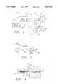
- FIG. 1is a cross-sectional view of an eye with the probe, in one aspect of the invention, operatively disposed to fragment the lens of the eye;
- FIG. 2is a side-elevation view of a further embodiment of the invention wherein a drive motor is configured as part of a handpiece;
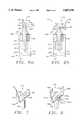
- FIG. 3ais an axial cross-section view of a coupling between a drive motor and a drive cable connector associated with the present invention
- FIG. 3bis an enlarged axial cross-section view of a rotary seal associated with the drive cable connector
- FIG. 4is an axial cross-section view of a proximal end of the handpiece associated with the present invention
- FIG. 5ais an axial cross-section view of a sheath disposed in a distal position to cover a rotary tip of the handpiece;
- FIG. 5bis an axial cross-section view of the sheath disposed in a proximal position to expose the rotary tip;
- FIG. 6ais a side-elevation view of a preferred configuration of the probe tip having a single cross member
- FIG. 6bis a front elevation view of the probe tip illustrated in FIG. 6a;
- FIG. 7is a perspective view of the probe tip illustrated in FIG. 6a;
- FIG. 8is a perspective view of a probe tip having two cross members
- FIG. 9a-9cis a series of axial cross-section views of the ocular lens and removal system, illustrating various steps in a method associated with the present invention
- FIG. 9aillustrates a step for inserting the probe and injecting a liquid to effect hydrodissection
- FIG. 9billustrates a step for creating an enclosed fluid flow for moving the lens into the rotating tip of a stationary probe
- FIG. 9cillustrates an advanced step of lens fragmentation wherein the fluid flow is greatly increased and the lens is substantially fragmented for ultimate removal from the capsule.
- FIG. 9dillustrates a step whereby a synthetic lens replacement material is introduced into the lens capsule following removal of the endogenous ophthalmic lens therefrom.
- FIG. 1An eye is illustrated in FIG. 1 and designated generally by the reference numeral 10.
- the eyeincludes the sclera 12 and a cornea 14 which define an inner cavity of the eye 10.
- a limbus 15provides a 1-2 mm wide transitional zone between the cornea 14 and the sclera 12.
- An iris 16comprises a ring of pigmented tissue which lies behind the cornea 14.
- a central opening in the iris 16is commonly referred to as a pupil 22.
- a lens structure 23is supported by the sclera 12 and lies between the iris 16 and the vitreous 24, a transparent gelatinous mass which fills the interior of the eye 10 behind the lens structure 23.
- the interior of the eye 10 which lies between the cornea 14 and the vitreous 24is divided into the two chambers, an anterior chamber 25 which lies between the cornea 14 and the plane of the iris 16, and a posterior chamber 26 which lies between the plane of the iris 16 and the vitreous 24.
- an imagepasses through the cornea 14 and the pupil 22 where the lens structure 23 functions to form a focused image onto a retina 27 at the back of the vitreous 24.
- Electrical impulsesare generated by the retina 27 and carried by an optic nerve (not shown) to the brain.
- the lens structure 23is of particular interest to the present invention.
- This structureincludes a lens 41 which in its natural state is generally elastic and transparent.
- This lens 41is enclosed in a lens capsule 43, the outer radius of which is supported by ciliary musculature 45.
- the ciliary musculature 45responds to an image out of focus by radially stretching the lens capsule 43 or by relaxing the radial stretch on the lens capsule 43.
- Thiscauses the enclosed lens 41 to vary its optical characteristics until the image is focused on the retina 27.
- the aging processdegrades the elasticity of the material forming the lens 41 so that accommodation becomes impaired as this ability of the eye to reshape the lens 41 decreases.
- Another condition associated with agingis the clouding or reduced transparency of the crystalline material which forms the lens 41.
- cataractsform in this manner, blindness typically results increasing the desirability of removing the cataractous lens to restore vision.
- an apparatus for removing the lens 41 from the lens capsule 43includes a control console 50 which houses a power supply and a motor controller that is operable by a foot pedal 52. Power from the control console 50 can be fed along a power cable 54 to a drive motor 56 which provides rotary power at a motor coupler 58.
- the motor controller in the console 50can be adapted to provide for variations in speed as well as rotational direction. These characteristics of the rotary power controller can be programmed to provide desirable speed profiles, such as ramping, sine wave or square wave speed variation cycles.
- This rotary poweris introduced from the drive motor 56 through a drive cable connector 61 and drive cable 62 to a handpiece 63 which includes a housing 64 and a probe 65.
- the probe 65When operatively disposed as illustrated, the probe 65 extends through a small incision in the limbus 15 of the eye 10 and into the lens capsule 43.
- the drive cable connector 61may also be adapted to receive input from an irrigation-aspiration apparatus 67 through a tube 68.
- control console 50, drive motor 56, foot pedal 52 and irrigation apparatus 67will generally be reusable in a non-sterile state.
- the drive cable connector 61, drive cable 62, and handpiece 63can either be disposable or adapted for limited reuse. In either case, these elements typically will be utilized in a sterile state.
- a key advantage of this embodiment of the inventionis that it facilitates implementation of a handpiece 63 which is smaller in size, lighter in weight and significantly more maneuverable than the handpieces associated with the phacoemulsification apparatus of the prior art.
- the drive motor 56is housed within and forms a portion of the control console 50.
- the power cable 54is foreshortened and exists only within the control console 50 such that the drive motor 56 and motor coupler 58 are integral with the control console 50.
- FIG. 2A further embodiment of the invention is illustrated in FIG. 2 wherein the drive motor 56a forms a portion of the handpiece 63a.
- elements which are similar to those previously describedare referred to with the same reference numeral followed by the lower case letter "a".
- the power cable 54aextends between the control console 50a and drive motor 56a.
- the drive motor 56ais included in the handpiece 63a so the rotary drive cable (not shown) is foreshortened and exists only within the handpiece 63a.
- the foot pedal 52may be replaced with a finger switch 52a.
- the control console 50awill typically be reusable and will be utilized in a non-sterile state.
- the power cable 54a and motor drive 56a of the handpiece 63amay be adapted for limited reuse, but the distal end of the handpiece 63a, including the probe 65a, will typically be disposable.
- the power cable 54a, drive motor 56a, and probe 65awill be utilized in a sterile state.
- the handpiece 63will typically have a length between 10 cm and 20 cm with the probe 65 accounting for about 1 cm to 4 cm of that length.
- the outside diameter of the handpieceis preferably between 7 mm and 15 mm while the probe 65 has a diameter between about 3 F (1 mm) and 9 F (3 mm).
- the drive cable connector 61Of particular interest to the present invention are the drive cable connector 61, drive cable 62 and handpiece 63. These elements are coupled to the drive motor 56 by inserting the drive cable connector 61 into the motor coupler 58 along an axis 69 as illustrated in FIG. 3a.
- the drive motor 56is located in an enclosure 70 having an inner bore 71 which extends through an annular projection forming the motor coupler 58.
- the drive motor 56produces the rotary power which is provided to the motor coupler 58 on a rotary shaft 72.
- this shaft 72is provided with an axial bore 74 which is slotted or otherwise shaped to a non-circular configuration.
- the motor coupler 58is adapted to receive the drive cable connector 61 and to releasably lock the drive cable connector 61 in place, for example with a gate lock 81.
- the gate lock 81includes a locking tab 83 which is slidably held in slots formed into the enclosure 70.
- the locking tab 83is provided with an aperture 87 which is movable between a first position wherein the drive cable connector 61 can be inserted into or removed from the motor coupler 58, and a second position wherein the drive cable connector 61 is locked to the motor coupler 58.
- the locking tab 83is provided with a thumb flange 90 which facilitates movement of the tab 83 between its first and second positions.
- the thumb flange 90is also configured to compress a spring 92 against the enclosure 70. This spring 92 biases the flange 90 and locking tab 83 in the locking position as illustrated in FIG. 3A.
- a retaining pin 94is fixed to the enclosure 70 and rides within a vertical slot 96 for limiting the distance of travel toward the locking position of the locking tab 83 when the drive cable connector 61 is absent.
- the drive cable connector 61includes a housing 101 which forms a cylindrical male fitting 103 which is configured to register with the inner bore 71 of the enclosure 70.
- This fitting 103has an inner bore 105 and an outwardly extending annular locking flange 107.
- a drive cable connector shaft 110is supported in a ball bearing 112 and is configured to register with the non-circular bore 74 of the motor coupler 58.
- the locking tab 83 of the motor coupler 58is initially depressed and the cylindrical fitting 103 is introduced through the aperture 87 into the inner bore 71 where the shaft 110 registers with the axial non-circular bore 74.
- the drive cable connector 61is moved into the motor coupler 58 until the annular flange 107 engages a shoulder 114 on the enclosure 70.
- the locking tab 83can be released permitting the spring 92 to move the tab to the locking position. This movement causes the aperture 87 to engage the flange 107 and lock the drive cable connector 61 to the motor coupler 58.
- the housing 101 of the drive cable connector 61has walls which define an inwardly extending annular flange 121 and an inner cavity 123 which is tapered to an axial bore 125 at the distal end of the drive cable connector 61.
- the ball bearing 112is located in the bore 105 and is held proximally of and against the flange 121 by a bearing retainer 126.
- the rotary motion imparted to the shaft 110is transferred to a flexible shaft or cable 127 which is supported within a flexible tube 129 by a helical bearing 130.
- the flexible tube 129has a lumen 132 with the same diameter as bore 125.
- the helical bearing 130defines with the cable 127 and the flexible tube 129 a helical channel or passage 133 which extends from the drive cable connector 61 to the handpiece 63.
- the elements 127-130form the rotary drive cable 62.
- irrigate and/or aspirate the operative siteIn a particular procedure it may be desirable to irrigate and/or aspirate the operative site. This is accomplished in one embodiment by connecting the irrigation/aspiration apparatus 67 through the tubing 68 to the housing 101. In the illustrated embodiment, fluid from the apparatus 67 is introduced into the cavity 123 and is communicated through the helical passage 133 in the drive cable 62 to the handpiece 63 and the distal end of the probe 65.
- irrigation/aspiration fluidbe isolated from the drive motor 56. This is accomplished in the illustrated embodiment by providing a high speed rotary face seal 134 which presses against and forms a fluid tight seal with a distally facing radial surface 136 of the annular flange 121.
- the seal 134is of particular interest to the present invention as shown in greater detail in FIG. 3b.
- the seal 134is a face seal formed from an elastomeric material and includes an enlarged generally cylindrical ring 138 which is seated against the flange 139 in a fixed relationship with the shaft 110.
- This ring 138is integral with a skirt 141 which has a generally conical or frustoconical configuration and extends proximally into contact with the surface 136.
- the skirt 141is highly compliant and extends increasingly radially outwardly with progressive positions in the proximal direction.
- the elastomeric characteristics of the seal 134bias the skirt 141 into sealing engagement with the surface 136 of the flange 121.
- the seal 134functions as a high speed rotary seal, making it particularly advantageous for use in the lens removal system.
- centrifugal forcecauses the skirt 141 to flare radially outwardly. This causes the pressure of the seal 134 against the surface 136 to decrease with an increasing speed of rotation.
- a preferred embodiment of this sealis manufactured by Forsheda Shaft Seal Corporation and is referred to as a Forsheda V-ring seal.
- the proximal end of the handpiece 63is provided with an elastomeric strain relief member 152 as illustrated in FIG. 4.
- This member 152is disposed around the drive cable 62 where it enters the housing 64 of the handpiece 63.
- the flexible tube 129is terminated, but the drive cable 127 and helical bearing 130 continue through the housing 64 within a bore 154 with the same diameter as the lumen 132 of flexible tube 129.
- FIG. 5aA preferred embodiment of the distal end of the handpiece 63 is illustrated in FIG. 5a.
- the probe 65 of the handpiece 63is illustrated to include a cannula 161 which is fixed to the housing 64 and provides an extension of bore 154.
- the drive cable 127 and supporting helical bearing 130 and the helical fluid passage 133extend into the cannula 161 to the distal end of the probe 65.
- the helical bearing 130is terminated, and a rotary tip 163 is fixed to the drive cable 127 and supported by a bushing 165.
- the probe 65is introduced into the lens capsule 43 with a needle structure. This is accomplished in the embodiment of FIG. 5a by providing an outer sheath 170 which is slidable relative to the cannula 161 and movable between a distal position wherein the rotary tip 163 is covered (as illustrated in FIG. 5a) and a proximal position wherein the rotary tip 163 is exposed (as illustrated in FIG. 5b).
- the outer sheath 170can be fixed to a nose cone 172 which is axially movable relative to the housing 64.
- the nose cone 172includes a proximal bore 174 which registers with a cylindrical surface 176 which projects from the distal end of the housing 64.
- the nose cone 172is configured to receive an O-ring 177 and associated retainer 178.
- the O-ringprovides a seal between the cannula 161 and the sheath 170. This seal prevents air from entering the operative site and disrupting the induced fluid flow, for example, during aspiration or during activation of the rotary tip 163. This seal also prevents fluids from escaping from the operative site.
- the friction created between the nose cone 172 and cylindrical surface 176 as well as between the O-ring 177 and the cannula 161may be sufficient to maintain the sheath 170 in either the forward or retracted position.
- the distal end of the protective sheath 170is preferably sharpened to facilitate puncture of the lens capsule 43 and entry into lens the 41.
- the configuration of the rotary tip 163is best illustrated in FIGS. 6a and 6b to include a reducer 179 supported on a shaft 180 which has an enlargement 181 at its proximal end. This enlargement 181 is fixed to the end of the drive cable 127 within the cannula 161 and proximally of the bushing 165. Distally of the bushing 165 a spacer 183 can be provided in fixed relationship with the shaft 180 to secure the rotary tip 163 at the distal end of the probe 65. Fluid is communicated to the operative site through the passage 133 and one or more axial slots 167 in the bushing 165.
- the reducer 179 at the distal end of the rotary tip 163includes a cross bar 185 which is fixed at its center transversely to the shaft 180 as illustrated in FIG. 7.
- the cross bar 185On opposite sides of shaft 180, the cross bar 185 has opposing arms 186 and 187 which are pitched at an angle ⁇ (best illustrated in FIG. 6) between 0° and 90°.
- the pitched arm 186When the shaft 180 is rotated, for example in the direction of arrow 188 in FIG. 6, the pitched arm 186 has a leading edge 189 and the pitched arm 187 has a leading edge 190.
- the cross bar 185functions as an impeller (in the form of a pitched blade turbine) which in a generally confined fluid environment will create a fluid flow of particular interest to the present invention.
- Rotation of the impellerinduces three-dimensional fluid flow with axial, radial and tangential components.
- the axial flow componentis of particular interest because it is primarily the axial component which draws the object to be reduced into contact with the reducer 179.
- the best compromise to induce the axial inflow desired for the present inventionis in a range of pitch angles ⁇ between 0° and 45°.
- the reducer 179can be provided with an axially extending member at each end of the cross bar 185. These axial members enhance the reducing action and are configured to be the first point of contact between the impeller and any object drawn into it by the fluid flow.
- the axial members, designated by the reference numerals 191 and 192 in FIG. 6extend generally axially of the outer ends of the crossbar 185.
- the axial member 191has a triangular configuration with a leading edge 193 which is disposed in a common axial plane with the leading edge 189.
- the axial member 192can be similarly constructed but with a leading edge 194 which is shorter in axial length than the axial member 191.
- This axial member 192has a triangular configuration which can be disposed in a common axial plane with the leading edge 190.
- the leading edges 189, 190, 193 and 194are preferably sharpened to facilitate cutting or other reduction of the lens 41.
- the reducer 179 illustrated in FIG. 8includes two cross members 185a and 185b which are disposed in generally perpendicular relationship on the shaft 180.
- the axial members 191a and 192aare disposed at opposite ends of the cross member 185a and are illustrated to be generally equal in axial dimension.
- a pair of axial members 191b and 192bare disposed at the ends of the cross member 185b and are also illustrated to be generally equal in axial dimension but shorter than the axial members 191a and 192a.
- the pitched arms 186, 186a, 186b, 187, 187a, and 187bpreferably have radial lengths of two to six times the radius of the shaft 180.
- the longer axial members 191, 191a, and 192ahave a preferred axial length about equal to the radial length of the pitched arms 186, 186a, 186b, 187, 187a, and 187b.
- the shorter axial members 192, 191b, and 192bpreferably have an axial length of about one-half the axial length of the longer axial members 191, 191a, and 192a.
- the pitched arms 186 and 187have a radial length of about 0.07 mm.
- the axial member 191has an axial length of about 1.0 mm while the axial member 192 has an axial length of about 0.5 mm.
- the pitched arms 186 and 187 and axial members 191 and 192are preferably formed of hardened stainless steel having a thickness of about 0.1 mm.
- reducer 179would generally include any impeller which induces axial flow upon rotation. Such impellers may or may not be additionally modified to provide axially extending members to enhance the reducing action.
- Preferred embodiments of the reducer 179are generally configured with one to six symmetrically or asymmetrically arranged pitched arms. Each of these pitched arms can either be radially oriented or inclined relative to the rotational axis.
- the present methodis intended for reducing in size an object disposed in a generally confined fluid medium environment within a living mammalian body.
- a rotary memberis inserted into the fluid medium where the axis of rotation and axial position of the rotary member is maintained generally stationary.
- the rotary memberis rotated at a speed sufficient to reduce the object when the object is moved into the rotary member.
- the rotary membermay be positioned into the fluid medium environment either by locating the rotary member at the distal end of a probe or by suspending the rotary member in a magnetic field.
- the method of the present inventionis intended to be carried out in an environment wherein the probe 65 can be held generally stationary and a flow of fluid in the environment will bring material to the rotary tip 163 for reduction.
- Thismay be an environment where fluid flow already exists or it may be an environment which is sufficiently closed that the impeller action of the cross bar 185 will produce a generally continuous flow into the reducer 179. This flow will carry any object present in the environment into the reducer 179 for reduction in accordance with the present invention.
- the word "reducing" and derivatives thereofis deemed to include cutting, macerating, shearing, tearing, emulsifying, dissecting, fragmenting, and otherwise dividing objects within the environment.
- the reductionoccurs when the object is in general contact with the reducer 179. This may include actual contact between the object and the reducer 179. However, it is also deemed to include those instances where there is no actual contact but sufficient proximity between the object and the reducer 179 for the desired reduction to occur.
- the apparatus previously discussedis particularly useful in a method for removing the lens 41 from the lens capsule 43.
- the sheath 170 described with reference to FIG. 5is moved to its forward or distal position covering the rotary tip 163 as shown in FIG. 5a.
- the sharp distal end of the sheath 170is exposed to facilitate introduction of the probe 65 through the anterior side of the lens capsule 43.
- a liquid 201such as a saline solution, can be introduced through the probe 65 into the lens capsule 43.
- the liquid 201will flow along the interior surfaces of the lens capsule 43 causing a separation of the lens capsule 43 from the lens 41.
- the method of separating the lens capsule from the lens by liquid injectionis generally referred to as hydrodissection.
- This hydrodissectionis of particular interest to the present invention as it initially functions to increase the mobility of the lens 41 within the lens capsule 43.
- the injected liquid 201also facilitates disposition of lens 41 in a liquid environment within the lens capsule 43.
- introduction of liquid 201can facilitate hydration and softening of the outer regions (lens cortex) of the lens 41.
- the flow of the liquid 201is illustrated by the arrows 202 in FIG. 9a.
- the sheath 170can be returned to its proximal position as illustrated in FIG. 5b either during or following the injection step. With the sheath 170 retracted, the rotary tip 163 is exposed.
- the control console 50activates the drive motor 56 and imparts rotary motion through the drive cable 62 to the rotary tip 163.
- the reducer 179begins to function as an impeller creating a fluid flow within the lens capsule 43.
- the lens 41moves into contact with the rotary tip 163, it is rapidly reduced into very small pieces.
- the outer portionsmay be particularly soft in which case they will preferentially tend to liquify under the high speed reducing action. In this manner, the initial reducing of the lens 41 tends to increase the amount of liquid within the capsule 43 subsequently enhancing the mobility of the unreduced lens under the fluid action created by the rotary tip 163.
- the handpiece 63 and probe 65can be held generally stationary within the lens capsule 43. There is no need to "search" with the probe 65 in order to reach the lens 41. Consequently, the likelihood of puncturing the lens capsule 43 by inadvertently over-extending the "reach" of the probe 65 is eliminated.
- Thisis a major advantage of the present invention over the prior art of phacoemulsification because a high degree of surgical skill and training is not required. Furthermore, the likelihood of tearing the lens capsule 43 at the point of probe entry as a result of probe manipulations, is greatly reduced.
- the probecan be held stationary while activation of the rotary tip 163 causes fluid flow as indicated by arrows 204 to move the unreduced portion of the lens 41 into the reducer 179.
- This movement of the unreduced lens 41 into the stationary probe 65is illustrated by arrow 203 in FIG. 9b.
- the axial inflow of fluid associated with this inventionacts to draw into the probe 65 the unreduced portions of the lens 41, hereinafter designated by the reference numeral 241.
- the discharge of fluid from the reducer 179reverses axial direction at a proximal end 210 of the lens capsule 43, flows along the lens capsule 43, and again reverses axial direction at a distal end 211 of the lens capsule 43, thus acting to push the unreduced portions of the lens 241 into the probe 65 as a result of the flow recirculation.
- rotation of the reducer 179functions to create a fluid flow within a relatively confined environment which moves the object to be reduced into the rotating reducer 179.
- the lens 41is completely reduced to small pieces as shown in FIG. 9c.
- the pieces of reduced lens materialare of sufficiently small in size to be easily removed from the intact lens capsule 43 by aspiration.
- the fluid and lens remnants within the capsule 43can be aspirated through the probe 65 or through a separate probe (not shown) leaving the capsule 43 generally intact but absent the previously enclosed lens 41.
- the outer sheath 170may provide a convenient means for aspiration of the fluid or may provide a means by which a separate probe can be introduced for aspiration.
- FIG. 9cshows completion of lens reduction such that the remnants of lens are sufficiently reduced in size to allow for their removal from the intact lens capsule 43 by aspiration/irrigation.
- Methods practiced in the prior artcommonly include implantation of a synthetic intraocular lens substitute, or to correct vision with glasses or contact lenses in the absence of an implanted lens substitute.
- a synthetic lens materialSLM
- SLMsynthetic lens material
- An advantage of the endocapsular procedure of the present inventionis that the lens capsule 43 is left intact during the lens removal operation so that it can still function as an enclosure for the injected lens material.
- a synthetic lens materialis to be introduced into the lens capsule 43, such injection can occur through the probe 65 or it can be accomplished by a separate probe (not shown). In either case, the method will not be complete until the probe 65 is removed from the lens capsule 43. This is accomplished in a preferred method by moving the sheath 170 to its distal position thereby covering the rotary tip 163 as illustrated in FIG. 5a. In this configuration, the probe 65 can easily be retracted from the capsule 43 and the eye 10.
- the speed of rotation of the reducer 179is of particular interest to the present invention since it not only provides the fluid flow but also produces the desired reduction of the lens 41.
- the most desirable speedwill of course depend upon the size and configuration of the reducer 179, the volume and shape of the generally confined environment, the viscosity of the fluid, the magnitude of fluid flow desired, and of course the speed of reduction desired. Other factors might include the hardness of the object being reduced. Speeds in a range between 10,000 and 300,000 rpm seem to provide the best compromise of these factors. A preferred range of speed for the lens removal process is 30,000 to 100,000 rpm.
- the preferred embodimentincludes the helical bearings 130 to support the cable 127 in the rotary drive cable 62.
- This bearingprovides minimal contact with the cable 127 while at the same time providing support along its entire length.
- the helical bearingis formed by a wire having a circular cross section, the contact between the helical wire bearing 130 and the cable 127 is along a helical line which provides for minimal contact support from the drive cable connector 61, through the handpiece 63, to the distal end of the probe 65.
- the rotary member of the present inventionneed not be mechanically supported on the tip of a handpiece probe, but can be made of a magnetic material and suspended in the fluid environment by a magnetic field.
- the magnetic fieldcan then be manipulated such that the rotary member remains generally laterally and axially stationary. Rotation of the rotary member on its rotational axis causes material within the fluid environment to be drawn by fluid flow to the rotary member where it is rapidly reduced.
- material within the fluid environment drawn to the tip of a handpiece probeneed not be reduced by direct mechanical interaction with the rotary member.
- rotation of the rotary member on the tip of a handpiece probecan be used to induce a fluid flow that draws the material into proximity with the probe tip where a secondary energy source, such as laser, ultrasound, or electrohydraulic shock waves, can be utilized to effect reduction of the material.
Landscapes
- Health & Medical Sciences (AREA)
- Ophthalmology & Optometry (AREA)
- Veterinary Medicine (AREA)
- Biomedical Technology (AREA)
- Heart & Thoracic Surgery (AREA)
- Vascular Medicine (AREA)
- Life Sciences & Earth Sciences (AREA)
- Animal Behavior & Ethology (AREA)
- General Health & Medical Sciences (AREA)
- Public Health (AREA)
- Engineering & Computer Science (AREA)
- Nuclear Medicine, Radiotherapy & Molecular Imaging (AREA)
- Surgery (AREA)
- Prostheses (AREA)
- Surgical Instruments (AREA)
- Eye Examination Apparatus (AREA)
- Eyeglasses (AREA)
- Medical Preparation Storing Or Oral Administration Devices (AREA)
- Endoscopes (AREA)
- Grinding And Polishing Of Tertiary Curved Surfaces And Surfaces With Complex Shapes (AREA)
- External Artificial Organs (AREA)
Abstract
Description
Claims (33)
Priority Applications (17)
| Application Number | Priority Date | Filing Date | Title |
|---|---|---|---|
| US07/984,229US5437678A (en) | 1992-11-30 | 1992-11-30 | Ophthalmic lens removal method and apparatus |
| NZ279161ANZ279161A (en) | 1992-11-30 | 1993-11-29 | Ophthalmic lens removal apparatus comprises a probe with a rotary lens reducing head |
| ES94903346TES2191027T3 (en) | 1992-11-30 | 1993-11-29 | APPARATUS TO REMOVE OPTICAL LENSES. |
| PCT/US1993/011581WO1994012132A1 (en) | 1992-11-30 | 1993-11-29 | Ophthalmic lens removal apparatus |
| BR9307552ABR9307552A (en) | 1992-11-30 | 1993-11-29 | Process for size reduction of object disposed in cavity of mammal organism apparatus for reducing object placed in closed liquid medium surgical reducer process for removing object from generally closed fluid environment |
| EP94903346AEP0673233B1 (en) | 1992-11-30 | 1993-11-29 | Ophthalmic lens removal apparatus |
| AT94903346TATE231373T1 (en) | 1992-11-30 | 1993-11-29 | DEVICE FOR REMOVAL OF AN OPHTHALMIC LENS |
| JP6513445AJPH08503639A (en) | 1992-11-30 | 1993-11-29 | Eye lens extraction device |
| DE69332657TDE69332657T2 (en) | 1992-11-30 | 1993-11-29 | DEVICE FOR REMOVING AN OPHTHALMIC LENS |
| KR1019950702176AKR100336215B1 (en) | 1992-11-30 | 1993-11-29 | Eye lens removal device |
| FI952621AFI952621A0 (en) | 1992-11-30 | 1993-11-29 | Eye lens removal device |
| AU59504/94AAU692142B2 (en) | 1992-11-30 | 1993-11-29 | Ophthalmic lens removal apparatus |
| CA002150239ACA2150239C (en) | 1992-11-30 | 1993-11-29 | Ophthalmic lens removal apparatus |
| US08/421,421US5690641A (en) | 1992-11-30 | 1995-04-11 | Rotary device for removing ophthalmic lens |
| NO952113ANO306443B1 (en) | 1992-11-30 | 1995-05-29 | Device for "on-site" reduction of an ophthalmic lens |
| US08/658,846US5871492A (en) | 1992-11-30 | 1996-05-31 | Rotary device for removing ophthalmic lens |
| US09/248,421US6117149A (en) | 1992-11-30 | 1999-02-11 | Rotary device and method for removing ophthalmic lens |
Applications Claiming Priority (1)
| Application Number | Priority Date | Filing Date | Title |
|---|---|---|---|
| US07/984,229US5437678A (en) | 1992-11-30 | 1992-11-30 | Ophthalmic lens removal method and apparatus |
Related Child Applications (1)
| Application Number | Title | Priority Date | Filing Date |
|---|---|---|---|
| US08/421,421Continuation-In-PartUS5690641A (en) | 1992-11-30 | 1995-04-11 | Rotary device for removing ophthalmic lens |
Publications (1)
| Publication Number | Publication Date |
|---|---|
| US5437678Atrue US5437678A (en) | 1995-08-01 |
Family
ID=25530398
Family Applications (4)
| Application Number | Title | Priority Date | Filing Date |
|---|---|---|---|
| US07/984,229Expired - LifetimeUS5437678A (en) | 1992-11-30 | 1992-11-30 | Ophthalmic lens removal method and apparatus |
| US08/421,421Expired - LifetimeUS5690641A (en) | 1992-11-30 | 1995-04-11 | Rotary device for removing ophthalmic lens |
| US08/658,846Expired - LifetimeUS5871492A (en) | 1992-11-30 | 1996-05-31 | Rotary device for removing ophthalmic lens |
| US09/248,421Expired - LifetimeUS6117149A (en) | 1992-11-30 | 1999-02-11 | Rotary device and method for removing ophthalmic lens |
Family Applications After (3)
| Application Number | Title | Priority Date | Filing Date |
|---|---|---|---|
| US08/421,421Expired - LifetimeUS5690641A (en) | 1992-11-30 | 1995-04-11 | Rotary device for removing ophthalmic lens |
| US08/658,846Expired - LifetimeUS5871492A (en) | 1992-11-30 | 1996-05-31 | Rotary device for removing ophthalmic lens |
| US09/248,421Expired - LifetimeUS6117149A (en) | 1992-11-30 | 1999-02-11 | Rotary device and method for removing ophthalmic lens |
Country Status (14)
| Country | Link |
|---|---|
| US (4) | US5437678A (en) |
| EP (1) | EP0673233B1 (en) |
| JP (1) | JPH08503639A (en) |
| KR (1) | KR100336215B1 (en) |
| AT (1) | ATE231373T1 (en) |
| AU (1) | AU692142B2 (en) |
| BR (1) | BR9307552A (en) |
| CA (1) | CA2150239C (en) |
| DE (1) | DE69332657T2 (en) |
| ES (1) | ES2191027T3 (en) |
| FI (1) | FI952621A0 (en) |
| NO (1) | NO306443B1 (en) |
| NZ (1) | NZ279161A (en) |
| WO (1) | WO1994012132A1 (en) |
Cited By (40)
| Publication number | Priority date | Publication date | Assignee | Title |
|---|---|---|---|---|
| WO1997045061A1 (en) | 1996-05-24 | 1997-12-04 | Sorensen John T | Rotary device for removing ophthalmic lens |
| US6042587A (en)* | 1994-07-15 | 2000-03-28 | Micro Medical Devices, Inc. | Foldable lens delivery system |
| EP1007129A4 (en)* | 1996-08-29 | 2000-08-02 | Team Medical Llc | Body fluids and solids drainage system |
| WO2000048520A1 (en)* | 1999-02-17 | 2000-08-24 | Bausch & Lomb Incorporated | Methods, apparatus and system for removal of lenses from mammalian eyes |
| US6217584B1 (en) | 1996-05-09 | 2001-04-17 | Aharon Lehrer | Method and a system for performing cataract surgery |
| WO2001034075A1 (en)* | 1998-11-05 | 2001-05-17 | Scieran Technologies, Inc. | A foot switch to proportionally control a medical cutting device |
| US6328747B1 (en)* | 1996-05-09 | 2001-12-11 | Itos Innovative Technology In Ocular Surgery, Ltd. | Method and a system for performing cataract surgery |
| WO2002015828A2 (en) | 2000-08-21 | 2002-02-28 | Bausch & Lomb Surgical, Inc. | Prevention of posterior capsular opacification by endocapsular circulation of chemical agents |
| US6358260B1 (en) | 1998-04-20 | 2002-03-19 | Med-Logics, Inc. | Automatic corneal shaper with two separate drive mechanisms |
| US6425905B1 (en) | 2000-11-29 | 2002-07-30 | Med-Logics, Inc. | Method and apparatus for facilitating removal of a corneal graft |
| US6428508B1 (en) | 2000-02-01 | 2002-08-06 | Enlighten Technologies, Inc. | Pulsed vacuum cataract removal system |
| US20030158567A1 (en)* | 2000-05-22 | 2003-08-21 | Joshua Ben-Nun | Cataract surgery devices and methods for using same |
| US6613056B1 (en)* | 1999-02-17 | 2003-09-02 | Misonix, Inc. | Ultrasonic probe with low-friction bushings |
| US6663644B1 (en) | 2000-06-02 | 2003-12-16 | Med-Logics, Inc. | Cutting blade assembly for a microkeratome |
| US6699285B2 (en) | 1999-09-24 | 2004-03-02 | Scieran Technologies, Inc. | Eye endoplant for the reattachment of a retina |
| US6702832B2 (en) | 1999-07-08 | 2004-03-09 | Med Logics, Inc. | Medical device for cutting a cornea that has a vacuum ring with a slitted vacuum opening |
| US20040097956A1 (en)* | 2002-09-27 | 2004-05-20 | Nidek Co., Ltd. | Intraocular lens injection instrument |
| AU2001260569B2 (en)* | 2000-05-22 | 2005-07-21 | Itos International Ltd | Cataract surgery devices and methods for using same |
| US6979328B2 (en) | 2001-01-18 | 2005-12-27 | The Regents Of The University Of California | Minimally invasive glaucoma surgical instrument and method |
| US20060036215A1 (en)* | 2004-08-12 | 2006-02-16 | Mikhail Boukhny | Surgical apparatus |
| US20060264990A1 (en)* | 2005-04-13 | 2006-11-23 | Safe Surgery Technologies, Llc | Capsulotomy instrument |
| US7311700B2 (en) | 2000-11-29 | 2007-12-25 | Med-Logics, Inc. | LASIK laminar flow system |
| US20080146989A1 (en)* | 2006-07-30 | 2008-06-19 | Jaime Zacharias | Anti-repulsion anti-clogging system and method for driving a dual-axis lensectomy probe |
| US20110282374A1 (en)* | 2009-02-04 | 2011-11-17 | Sandeep Ambardekar | Disposable and reusable morcellator |
| US8939927B2 (en) | 2010-12-16 | 2015-01-27 | Alcon Research, Ltd. | Systems and methods for small bore aspiration |
| US20160067091A1 (en)* | 2014-09-04 | 2016-03-10 | Alcon Pharmaceuticals Ltd. | Surgical hand piece for cataract removal |
| US20190133825A1 (en)* | 2017-05-04 | 2019-05-09 | Iantech, Inc. | Devices and methods for ocular surgery |
| US10463535B2 (en) | 2014-09-17 | 2019-11-05 | Carl Zeiss Meditec Cataract Technology Inc. | Devices and methods for the removal of lenticular tissue |
| US10478334B2 (en) | 2014-09-17 | 2019-11-19 | Carl Zeiss Meditec Cataract Technology Inc. | Devices and methods for cutting lenticular tissue |
| US10624785B2 (en) | 2016-01-30 | 2020-04-21 | Carl Zeiss Meditec Cataract Technology Inc. | Devices and methods for ocular surgery |
| US10905591B1 (en) | 2019-07-22 | 2021-02-02 | Tsontcho Ianchulev | Methods and devices for increasing aqueous drainage of the eye |
| US10932951B2 (en) | 2017-12-14 | 2021-03-02 | Carl Zeiss Meditec Cataract Technology Inc. | Devices and methods for ocular surgery |
| US11058578B2 (en)* | 2017-06-14 | 2021-07-13 | Johnson & Johnson Surgical Vision, Inc. | Convertible phacoemulsification i/a sleeve and mechanical activation mechanism |
| US11241335B2 (en) | 2019-02-01 | 2022-02-08 | Carl Zeiss Meditec Cataract Technology Inc. | Ophthalmic cutting instruments having integrated aspiration pump |
| US11413188B2 (en) | 2016-10-26 | 2022-08-16 | Carl Zeiss Meditec Cataract Technology Inc. | Devices and methods for cutting a lens in an eye |
| US11638660B2 (en) | 2018-06-05 | 2023-05-02 | Carl Zeiss Meditec Cataract Technology Inc. | Ophthalmic microsurgical tools, systems, and methods of use |
| US11730625B2 (en) | 2019-05-17 | 2023-08-22 | Carl Zeiss Meditec Cataract Technology Inc. | Ophthalmic cutting instruments having integrated aspiration pump |
| US20230263662A1 (en)* | 2018-08-25 | 2023-08-24 | Thad Anthony Labbe | Dual helical coil ophthalmic surgical instruments for removal of lens materials and methods of use |
| US11801163B2 (en) | 2019-06-07 | 2023-10-31 | Carl Zeiss Meditec Cataract Technology Inc. | Multi-stage trigger for ophthalmology cutting tool |
| US12310892B2 (en) | 2021-09-10 | 2025-05-27 | Iantrek, Inc. | Methods and devices for increasing aqueous drainage of the eye |
Families Citing this family (97)
| Publication number | Priority date | Publication date | Assignee | Title |
|---|---|---|---|---|
| US7166117B2 (en) | 1996-02-07 | 2007-01-23 | Hellenkamp Johann F | Automatic surgical device and control assembly for cutting a cornea |
| US20070244496A1 (en)* | 1996-02-07 | 2007-10-18 | Hellenkamp Johann F | Automatic surgical device and control assembly for cutting a cornea |
| US6129734A (en)* | 1997-01-21 | 2000-10-10 | Shturman Cardiology Systems, Inc. | Rotational atherectomy device with radially expandable prime mover coupling |
| US6156049A (en)* | 1997-04-11 | 2000-12-05 | Coherent Inc. | Method and apparatus for transurethral resection of the prostate |
| US6077272A (en)* | 1997-08-22 | 2000-06-20 | Bausch & Lomb Surgical, Inc. | Detection of intraocular surgical scissors |
| US5951579A (en)* | 1997-10-06 | 1999-09-14 | Dykes; Ronald E. | Incision guide for intra-ocular surgery |
| US6024749A (en)* | 1997-10-27 | 2000-02-15 | Shturman Cardiology Systems, Inc. | Rotational atherectomy device with improved exchangeable drive shaft cartridge |
| US6077282A (en)* | 1997-10-27 | 2000-06-20 | Shturman Cardiology Systems, Inc. | Rotational atherectomy device with exchangeable drive shaft cartridge |
| US6537281B1 (en)* | 1999-03-22 | 2003-03-25 | Valdemar Portney | Corrective intraocular lens system, intraocular lenses, and lens handling and installation devices for use therewith |
| US7655016B2 (en)* | 1999-09-17 | 2010-02-02 | Covidien | Mechanical pump for removal of fragmented matter and methods of manufacture and use |
| AU778076B2 (en)* | 1999-09-17 | 2004-11-11 | Tyco Healthcare Group Lp | Mechanical pump for removal of fragmented matter and methods of manufacture and use |
| JP3869607B2 (en)* | 2000-01-06 | 2007-01-17 | 株式会社ニデック | Cornea surgery device |
| US20040039401A1 (en)* | 2000-03-31 | 2004-02-26 | Chow Alan Y. | Implant instrument |
| US6432078B1 (en)* | 2000-06-19 | 2002-08-13 | Gholam A. Peyman | System and method for removing cataract or other cells in an eye using water jet and suction |
| US7041078B1 (en) | 2000-06-19 | 2006-05-09 | Peyman Gholam A | System and method for removing cataract or other cells in an eye using water jet and suction |
| US6527736B1 (en)* | 2000-10-23 | 2003-03-04 | Grieshaber & Co. Ag Schaffhausen | Device for use in ophthalmologic procedures |
| US20020058904A1 (en)* | 2000-11-08 | 2002-05-16 | Robert Boock | Thrombus removal device |
| US6517560B1 (en) | 2000-11-27 | 2003-02-11 | Duke University | Hand-held surgical instruments employing magnetic couplings for simultaneous rotary and longitudinal oscillations of distal workpieces |
| US6478681B1 (en) | 2000-11-27 | 2002-11-12 | Duke University | Magnetic couplings for imparting simultaneous rotary and longitudinal oscillations |
| US8486140B2 (en)* | 2001-01-30 | 2013-07-16 | Timothy R. Willis | Refractive intraocular implant lens and method |
| US20070142912A1 (en)* | 2001-01-30 | 2007-06-21 | Willis Timothy R | Refractive intraocular implant lens and method |
| AR032840A1 (en) | 2001-02-23 | 2003-11-26 | Ras Holding Corp | SURGICAL SHEET USED WITH A SURGICAL INSTRUMENT TO MAKE INCISIONS IN IMPLANTS IN EYE SCLERTIC |
| US6830555B2 (en)* | 2001-10-09 | 2004-12-14 | Advanced Medical Optics | Multi-functional second instrument for cataract removal |
| US20030088253A1 (en)* | 2001-11-07 | 2003-05-08 | Seil Randolph L | Dual action ophthalmic implant extractor |
| US6610059B1 (en)* | 2002-02-25 | 2003-08-26 | Hs West Investments Llc | Endoscopic instruments and methods for improved bubble aspiration at a surgical site |
| US7037296B2 (en)* | 2002-04-04 | 2006-05-02 | Advanced Medical Optics, Inc. | Curved multi-purpose phacoemulsification needle |
| US20060253056A1 (en)* | 2002-04-04 | 2006-11-09 | Advanced Medical Optics, Inc. | Multi-purpose phacoemulsification needle |
| AU2003241530A1 (en) | 2002-05-20 | 2003-12-12 | Refocus Group, Inc. | System and method for determining a position for a scleral pocket for a scleral prosthesis |
| US7547304B2 (en)* | 2002-12-19 | 2009-06-16 | Gore Enterprise Holdings, Inc. | Guidewire-centering catheter tip |
| KR101080473B1 (en) | 2003-04-07 | 2011-11-04 | 테크노라스 게엠베하 옵탈몰로지쉐 시스템 | Microkeratome, Microkeratome Fixation Ring and Microkeratome Cutting Head |
| US7351219B2 (en)* | 2004-01-08 | 2008-04-01 | Alcon, Inc. | Method and instrumentation for cooling a surgical incision |
| US7959608B2 (en) | 2004-04-27 | 2011-06-14 | The Spectranetics Corporation | Thrombectomy and soft debris removal device |
| US8920402B2 (en) | 2004-04-27 | 2014-12-30 | The Spectranetics Corporation | Thrombectomy and soft debris removal device |
| US8287484B2 (en) | 2006-05-02 | 2012-10-16 | Abbott Medical Optics Inc. | Multi-purpose phacoemulsification needle |
| US8491528B2 (en)* | 2006-11-09 | 2013-07-23 | Abbott Medical Optics Inc. | Critical alignment of fluidics cassettes |
| US9295765B2 (en)* | 2006-11-09 | 2016-03-29 | Abbott Medical Optics Inc. | Surgical fluidics cassette supporting multiple pumps |
| US8414534B2 (en) | 2006-11-09 | 2013-04-09 | Abbott Medical Optics Inc. | Holding tank devices, systems, and methods for surgical fluidics cassette |
| US9522221B2 (en) | 2006-11-09 | 2016-12-20 | Abbott Medical Optics Inc. | Fluidics cassette for ocular surgical system |
| US10959881B2 (en) | 2006-11-09 | 2021-03-30 | Johnson & Johnson Surgical Vision, Inc. | Fluidics cassette for ocular surgical system |
| US8961551B2 (en) | 2006-12-22 | 2015-02-24 | The Spectranetics Corporation | Retractable separating systems and methods |
| US7909882B2 (en)* | 2007-01-19 | 2011-03-22 | Albert Stinnette | Socket and prosthesis for joint replacement |
| US8317845B2 (en)* | 2007-01-19 | 2012-11-27 | Alexa Medical, Llc | Screw and method of use |
| US10363166B2 (en) | 2007-05-24 | 2019-07-30 | Johnson & Johnson Surgical Vision, Inc. | System and method for controlling a transverse phacoemulsification system using sensed data |
| US10596032B2 (en) | 2007-05-24 | 2020-03-24 | Johnson & Johnson Surgical Vision, Inc. | System and method for controlling a transverse phacoemulsification system with a footpedal |
| US10485699B2 (en) | 2007-05-24 | 2019-11-26 | Johnson & Johnson Surgical Vision, Inc. | Systems and methods for transverse phacoemulsification |
| US10342701B2 (en)* | 2007-08-13 | 2019-07-09 | Johnson & Johnson Surgical Vision, Inc. | Systems and methods for phacoemulsification with vacuum based pumps |
| DE102007044790A1 (en) | 2007-09-19 | 2009-04-02 | Dieter Mann | One-hand device for eye surgery |
| US8201942B2 (en)* | 2008-04-02 | 2012-06-19 | Refocus Group, Inc. | System and method for identifying a position to insert a scleral prosthesis into an eye |
| US8034022B2 (en) | 2008-04-08 | 2011-10-11 | Cook Medical Technologies Llc | Weeping balloon catheter |
| EP3156012B1 (en)* | 2008-11-07 | 2021-10-20 | Johnson & Johnson Surgical Vision, Inc. | Adjustable foot pedal control for ophthalmic surgery |
| US9795507B2 (en) | 2008-11-07 | 2017-10-24 | Abbott Medical Optics Inc. | Multifunction foot pedal |
| US10349925B2 (en) | 2008-11-07 | 2019-07-16 | Johnson & Johnson Surgical Vision, Inc. | Method for programming foot pedal settings and controlling performance through foot pedal variation |
| WO2010054145A1 (en) | 2008-11-07 | 2010-05-14 | Abbott Medical Optics Inc. | Surgical cassette apparatus |
| CA2743086C (en) | 2008-11-07 | 2017-12-05 | Abbott Medical Optics Inc. | Automatically pulsing different aspiration levels to an ocular probe |
| EP2373265B1 (en) | 2008-11-07 | 2016-03-09 | Abbott Medical Optics Inc. | Controlling of multiple pumps |
| AU2009313402C1 (en) | 2008-11-07 | 2015-10-15 | Johnson & Johnson Surgical Vision, Inc. | Automatically switching different aspiration levels and/or pumps to an ocular probe |
| US9492317B2 (en) | 2009-03-31 | 2016-11-15 | Abbott Medical Optics Inc. | Cassette capture mechanism |
| US8623040B2 (en) | 2009-07-01 | 2014-01-07 | Alcon Research, Ltd. | Phacoemulsification hook tip |
| US20110137231A1 (en)* | 2009-12-08 | 2011-06-09 | Alcon Research, Ltd. | Phacoemulsification Hand Piece With Integrated Aspiration Pump |
| US20110144567A1 (en)* | 2009-12-15 | 2011-06-16 | Alcon Research, Ltd. | Phacoemulsification Hand Piece With Integrated Aspiration Pump and Cartridge |
| US8551130B2 (en)* | 2010-02-18 | 2013-10-08 | Cardiovascular Systems, Inc. | Therapeutic agent delivery system, device and method for localized application of therapeutic substances to a biological conduit |
| EP2552330B1 (en)* | 2010-03-29 | 2015-05-27 | Nigel Morlet | Improved needle tip for surgical instrument |
| US10258505B2 (en) | 2010-09-17 | 2019-04-16 | Alcon Research, Ltd. | Balanced phacoemulsification tip |
| US8475480B2 (en) | 2011-01-04 | 2013-07-02 | Alcon Research Ltd | Multi-sleeved surgical ultrasonic vibrating tool suited for phacoemulsification in a manner that prevents thermal injury to ocular tissue |
| ITMI20110957A1 (en) | 2011-05-26 | 2012-11-27 | Pizzuto Rodolfo | PORTABLE AND WEARABLE SYSTEM FOR THE ACQUISITION, VISUALIZATION, STORAGE AND NEXT PROCESSING OF THE ELECTROCARDIOGRAPHIC SIGNAL (ECG), FOR THE RECOGNITION OF ARITHMIC AND ISCHEMIC EVENTS, WITH REMOTE TRANSMISSION |
| WO2013016698A1 (en)* | 2011-07-28 | 2013-01-31 | Spine View, Inc. | Discectomy devices and related methods |
| US8597318B2 (en) | 2011-08-08 | 2013-12-03 | Refocus Group, Inc. | Apparatus and method for forming incisions in ocular tissue |
| US9517162B2 (en)* | 2011-11-30 | 2016-12-13 | Alcon Research, Ltd. | Retinal surgery |
| WO2013142009A1 (en) | 2012-03-17 | 2013-09-26 | Abbott Medical Optics, Inc. | Surgical cassette |
| CA2882220A1 (en) | 2012-12-11 | 2014-06-19 | Alcon Research Ltd. | Phacoemulsification hand piece with integrated aspiration and irrigation pump |
| US9962288B2 (en) | 2013-03-07 | 2018-05-08 | Novartis Ag | Active acoustic streaming in hand piece for occlusion surge mitigation |
| US9283040B2 (en) | 2013-03-13 | 2016-03-15 | The Spectranetics Corporation | Device and method of ablative cutting with helical tip |
| US9291663B2 (en) | 2013-03-13 | 2016-03-22 | The Spectranetics Corporation | Alarm for lead insulation abnormality |
| US9456872B2 (en) | 2013-03-13 | 2016-10-04 | The Spectranetics Corporation | Laser ablation catheter |
| US10383691B2 (en) | 2013-03-13 | 2019-08-20 | The Spectranetics Corporation | Last catheter with helical internal lumen |
| US9693896B2 (en) | 2013-03-15 | 2017-07-04 | Novartis Ag | Systems and methods for ocular surgery |
| US10842532B2 (en) | 2013-03-15 | 2020-11-24 | Spectranetics Llc | Medical device for removing an implanted object |
| US9668765B2 (en) | 2013-03-15 | 2017-06-06 | The Spectranetics Corporation | Retractable blade for lead removal device |
| US9750638B2 (en) | 2013-03-15 | 2017-09-05 | Novartis Ag | Systems and methods for ocular surgery |
| US9915274B2 (en) | 2013-03-15 | 2018-03-13 | Novartis Ag | Acoustic pumps and systems |
| US9918737B2 (en) | 2013-03-15 | 2018-03-20 | The Spectranetics Corporation | Medical device for removing an implanted object |
| US9545337B2 (en) | 2013-03-15 | 2017-01-17 | Novartis Ag | Acoustic streaming glaucoma drainage device |
| US9980743B2 (en) | 2013-03-15 | 2018-05-29 | The Spectranetics Corporation | Medical device for removing an implanted object using laser cut hypotubes |
| WO2014151814A1 (en) | 2013-03-15 | 2014-09-25 | The Spectranetics Corporation | Surgical instrument for removing an implanted object |
| US9126219B2 (en) | 2013-03-15 | 2015-09-08 | Alcon Research, Ltd. | Acoustic streaming fluid ejector |
| US10448999B2 (en) | 2013-03-15 | 2019-10-22 | The Spectranetics Corporation | Surgical instrument for removing an implanted object |
| US12053203B2 (en) | 2014-03-03 | 2024-08-06 | Spectranetics, Llc | Multiple configuration surgical cutting device |
| EP3113701B1 (en) | 2014-03-03 | 2020-07-22 | The Spectranetics Corporation | Multiple configuration surgical cutting device |
| US10405924B2 (en) | 2014-05-30 | 2019-09-10 | The Spectranetics Corporation | System and method of ablative cutting and vacuum aspiration through primary orifice and auxiliary side port |
| USD765243S1 (en) | 2015-02-20 | 2016-08-30 | The Spectranetics Corporation | Medical device handle |
| USD770616S1 (en) | 2015-02-20 | 2016-11-01 | The Spectranetics Corporation | Medical device handle |
| JP6622021B2 (en)* | 2015-07-29 | 2019-12-18 | 株式会社貝印刃物開発センター | Ophthalmic knife |
| EP3319553B1 (en) | 2015-08-14 | 2024-01-31 | Willis, Timothy R. | Intraocular lenses (iols) and related assemblies |
| JP6598155B2 (en)* | 2015-12-16 | 2019-10-30 | 株式会社日本未来医療研究所 | Vitrectomy instrument |
| WO2018055431A1 (en)* | 2016-09-20 | 2018-03-29 | Gavanescu Cosmin Adrian | Surgery device |
| JP2020531144A (en) | 2017-08-23 | 2020-11-05 | リフォーカス グループ、インコーポレイテッド | Surgical tools for forming incisions in ocular tissue, as well as related devices and methods, with a tip that provides visibility. |
| GR20200100612A (en)* | 2020-10-09 | 2022-05-09 | Αναστασιος Κωνσταντινου Χαρωνης | Modified homoaxial trocar for the insertion of tools and the maintenance of intraocular pressure in eye's anterior chamber surgery |
Citations (25)
| Publication number | Priority date | Publication date | Assignee | Title |
|---|---|---|---|---|
| US3818913A (en)* | 1972-08-30 | 1974-06-25 | M Wallach | Surgical apparatus for removal of tissue |
| US3976077A (en)* | 1975-02-03 | 1976-08-24 | Kerfoot Jr Franklin W | Eye surgery device |
| US4002169A (en)* | 1972-04-18 | 1977-01-11 | Cupler Ii John A | Method and apparatus for performing surgery without tissue incision |
| US4061146A (en)* | 1976-04-15 | 1977-12-06 | The United States Of America As Represented By The Administrator Of The National Aeronautics And Space Administration | Tissue macerating instrument |
| US4167944A (en)* | 1977-06-27 | 1979-09-18 | Surgical Design Corp. | Rotatable surgical cutting instrument with improved cutter blade wear |
| US4289131A (en)* | 1979-05-17 | 1981-09-15 | Ergo Instruments, Inc. | Surgical power tool |
| US4368734A (en)* | 1978-01-27 | 1983-01-18 | Surgical Design Corp. | Surgical instrument |
| US4445509A (en)* | 1982-02-04 | 1984-05-01 | Auth David C | Method and apparatus for removal of enclosed abnormal deposits |
| EP0147192A2 (en)* | 1984-01-03 | 1985-07-03 | Kensey Nash Corporation | Recanalisation catheter with cutter head |
| US4646736A (en)* | 1984-09-10 | 1987-03-03 | E. R. Squibb & Sons, Inc. | Transluminal thrombectomy apparatus |
| US4681106A (en)* | 1985-08-12 | 1987-07-21 | Intravascular Surgical Instruments, Inc. | Catheter based surgical methods and apparatus therefor |
| US4700705A (en)* | 1985-08-12 | 1987-10-20 | Intravascular Surgical Instruments, Inc. | Catheter based surgical methods and apparatus therefor |
| US4770174A (en)* | 1983-01-21 | 1988-09-13 | Brimfield Precision, Inc. | Rotary cutting scissors for surgery |
| EP0286415A2 (en)* | 1987-04-09 | 1988-10-12 | John Ewart Alfred Wickham | Tissue disintegrator |
| WO1989000834A1 (en)* | 1987-07-30 | 1989-02-09 | Intravascular Surgical Instruments, Inc. | Stone destroying catheter |
| EP0310685A1 (en)* | 1985-11-22 | 1989-04-12 | Kontron-Holding Ag | Angioplasty catheter |
| US4823793A (en)* | 1985-10-30 | 1989-04-25 | The United States Of America As Represented By The Administrator Of The National Aeronuautics & Space Administration | Cutting head for ultrasonic lithotripsy |
| US4825865A (en)* | 1987-05-01 | 1989-05-02 | Jerry Zelman | Apparatus and method for extracting cataract tissue |
| DE3801318A1 (en)* | 1988-01-19 | 1989-07-27 | Stocksmeier Uwe | MEDICAL CATHETER WITH CUTTER |
| GB2239060A (en)* | 1989-12-12 | 1991-06-19 | Forsheda Ab | A shaft sealing arrangement |
| US5057098A (en)* | 1987-05-01 | 1991-10-15 | Ophthalmocare, Inc. | Apparatus and method for extracting cataract tissue |
| US5074867A (en)* | 1990-05-18 | 1991-12-24 | Wilk Peter J | Surgical instrument assembly and related surgical method |
| WO1992011816A2 (en)* | 1991-01-09 | 1992-07-23 | Endomedix Corporation | Method and device for intracorporeal liquidization of tissue and/or intracorporeal fragmentation of calculi during endoscopic surgical procedures |
| US5133729A (en)* | 1990-08-17 | 1992-07-28 | Smith & Nephew Dyonics Inc. | Motor driven hand piece for a surgical tool |
| US5154696A (en)* | 1991-04-08 | 1992-10-13 | Shearing Steven P | Phacoemulsification, irrigation and aspiration method and apparatus |
Family Cites Families (9)
| Publication number | Priority date | Publication date | Assignee | Title |
|---|---|---|---|---|
| GB286415A (en)* | 1927-01-13 | 1928-03-08 | John George Brenner | A new or improved machine for peeling potatoes and for like purposes |
| US3732858A (en)* | 1968-09-16 | 1973-05-15 | Surgical Design Corp | Apparatus for removing blood clots, cataracts and other objects from the eye |
| US4608050A (en)* | 1983-07-21 | 1986-08-26 | Innovative Surgical Products, Inc. | Correction of defects in the eye and compositions therefor |
| US5041082A (en)* | 1986-06-16 | 1991-08-20 | Samuel Shiber | Mechanical atherectomy system and method |
| US4649919A (en)* | 1985-01-23 | 1987-03-17 | Precision Surgical Instruments, Inc. | Surgical instrument |
| US4747821A (en)* | 1986-10-22 | 1988-05-31 | Intravascular Surgical Instruments, Inc. | Catheter with high speed moving working head |
| WO1989003661A1 (en)* | 1987-10-26 | 1989-05-05 | Endotherapeutics | Trocar assembly with improved latch |
| ES2047586T3 (en)* | 1988-03-04 | 1994-03-01 | Angiomed Ag | PROCEDURE AND DEVICE TO REMOVE DEPOSITS OF MATERIAL IN VESSELS AND LIVING BODIES. |
| DE3906301A1 (en)* | 1988-04-28 | 1989-12-14 | Olympus Optical Co | Surgical resection instrument |
- 1992
- 1992-11-30USUS07/984,229patent/US5437678A/ennot_activeExpired - Lifetime
- 1993
- 1993-11-29AUAU59504/94Apatent/AU692142B2/ennot_activeCeased
- 1993-11-29FIFI952621Apatent/FI952621A0/ennot_activeApplication Discontinuation
- 1993-11-29ESES94903346Tpatent/ES2191027T3/ennot_activeExpired - Lifetime
- 1993-11-29NZNZ279161Apatent/NZ279161A/enunknown
- 1993-11-29CACA002150239Apatent/CA2150239C/ennot_activeExpired - Fee Related
- 1993-11-29ATAT94903346Tpatent/ATE231373T1/ennot_activeIP Right Cessation
- 1993-11-29EPEP94903346Apatent/EP0673233B1/ennot_activeExpired - Lifetime
- 1993-11-29JPJP6513445Apatent/JPH08503639A/enactivePending
- 1993-11-29KRKR1019950702176Apatent/KR100336215B1/ennot_activeExpired - Fee Related
- 1993-11-29DEDE69332657Tpatent/DE69332657T2/ennot_activeExpired - Fee Related
- 1993-11-29WOPCT/US1993/011581patent/WO1994012132A1/enactiveIP Right Grant
- 1993-11-29BRBR9307552Apatent/BR9307552A/ennot_activeIP Right Cessation
- 1995
- 1995-04-11USUS08/421,421patent/US5690641A/ennot_activeExpired - Lifetime
- 1995-05-29NONO952113Apatent/NO306443B1/ennot_activeIP Right Cessation
- 1996
- 1996-05-31USUS08/658,846patent/US5871492A/ennot_activeExpired - Lifetime
- 1999
- 1999-02-11USUS09/248,421patent/US6117149A/ennot_activeExpired - Lifetime
Patent Citations (27)
| Publication number | Priority date | Publication date | Assignee | Title |
|---|---|---|---|---|
| US4002169A (en)* | 1972-04-18 | 1977-01-11 | Cupler Ii John A | Method and apparatus for performing surgery without tissue incision |
| US3818913A (en)* | 1972-08-30 | 1974-06-25 | M Wallach | Surgical apparatus for removal of tissue |
| US3976077A (en)* | 1975-02-03 | 1976-08-24 | Kerfoot Jr Franklin W | Eye surgery device |
| US4061146A (en)* | 1976-04-15 | 1977-12-06 | The United States Of America As Represented By The Administrator Of The National Aeronautics And Space Administration | Tissue macerating instrument |
| US4167944A (en)* | 1977-06-27 | 1979-09-18 | Surgical Design Corp. | Rotatable surgical cutting instrument with improved cutter blade wear |
| US4368734A (en)* | 1978-01-27 | 1983-01-18 | Surgical Design Corp. | Surgical instrument |
| US4289131A (en)* | 1979-05-17 | 1981-09-15 | Ergo Instruments, Inc. | Surgical power tool |
| US4445509A (en)* | 1982-02-04 | 1984-05-01 | Auth David C | Method and apparatus for removal of enclosed abnormal deposits |
| US4770174A (en)* | 1983-01-21 | 1988-09-13 | Brimfield Precision, Inc. | Rotary cutting scissors for surgery |
| EP0147192A2 (en)* | 1984-01-03 | 1985-07-03 | Kensey Nash Corporation | Recanalisation catheter with cutter head |
| US4631052A (en)* | 1984-01-03 | 1986-12-23 | Intravascular Surgical Instruments, Inc. | Method and apparatus for surgically removing remote deposits |
| US4646736A (en)* | 1984-09-10 | 1987-03-03 | E. R. Squibb & Sons, Inc. | Transluminal thrombectomy apparatus |
| US4700705A (en)* | 1985-08-12 | 1987-10-20 | Intravascular Surgical Instruments, Inc. | Catheter based surgical methods and apparatus therefor |
| US4681106A (en)* | 1985-08-12 | 1987-07-21 | Intravascular Surgical Instruments, Inc. | Catheter based surgical methods and apparatus therefor |
| US4823793A (en)* | 1985-10-30 | 1989-04-25 | The United States Of America As Represented By The Administrator Of The National Aeronuautics & Space Administration | Cutting head for ultrasonic lithotripsy |
| EP0310685A1 (en)* | 1985-11-22 | 1989-04-12 | Kontron-Holding Ag | Angioplasty catheter |
| EP0286415A2 (en)* | 1987-04-09 | 1988-10-12 | John Ewart Alfred Wickham | Tissue disintegrator |
| US5057098A (en)* | 1987-05-01 | 1991-10-15 | Ophthalmocare, Inc. | Apparatus and method for extracting cataract tissue |
| US4825865A (en)* | 1987-05-01 | 1989-05-02 | Jerry Zelman | Apparatus and method for extracting cataract tissue |
| US4811735A (en)* | 1987-07-30 | 1989-03-14 | Kensey Nash Corporation | Stone destroying catheter and method of use |
| WO1989000834A1 (en)* | 1987-07-30 | 1989-02-09 | Intravascular Surgical Instruments, Inc. | Stone destroying catheter |
| DE3801318A1 (en)* | 1988-01-19 | 1989-07-27 | Stocksmeier Uwe | MEDICAL CATHETER WITH CUTTER |
| GB2239060A (en)* | 1989-12-12 | 1991-06-19 | Forsheda Ab | A shaft sealing arrangement |
| US5074867A (en)* | 1990-05-18 | 1991-12-24 | Wilk Peter J | Surgical instrument assembly and related surgical method |
| US5133729A (en)* | 1990-08-17 | 1992-07-28 | Smith & Nephew Dyonics Inc. | Motor driven hand piece for a surgical tool |
| WO1992011816A2 (en)* | 1991-01-09 | 1992-07-23 | Endomedix Corporation | Method and device for intracorporeal liquidization of tissue and/or intracorporeal fragmentation of calculi during endoscopic surgical procedures |
| US5154696A (en)* | 1991-04-08 | 1992-10-13 | Shearing Steven P | Phacoemulsification, irrigation and aspiration method and apparatus |
Non-Patent Citations (8)
| Title |
|---|
| "Recanalization of Obstructed Arteries and a Flexible, Rotating tip Catheter", Kenneth R. Kensey MD, 1987. |
| "The development and application of a new surgical device-the Endoscopic Liquidiser and Surgical Aspirator (ELSA)", K. T. Ison et al. 1989. |
| Miller, F. J., Kensey, D. R., Nash, John E.; Experimental Percutaneous Gallstone Lithotripsy: Results in Swine, Radiology165: 387 389, 1987.* |
| Miller, F. J., Kensey, D. R., Nash, John E.; Experimental Percutaneous Gallstone Lithotripsy: Results in Swine, Radiology165: 387-389, 1987. |
| Phacotmesis Distributed by Dr. Anis at May 1993 Conference of the American Society of Cataract and Refractive Surgery.* |
| Phacotmesis--Distributed by Dr. Anis at May 1993 Conference of the American Society of Cataract and Refractive Surgery. |
| Recanalization of Obstructed Arteries and a Flexible, Rotating tip Catheter , Kenneth R. Kensey MD, 1987.* |
| The development and application of a new surgical device the Endoscopic Liquidiser and Surgical Aspirator (ELSA) , K. T. Ison et al. 1989.* |
Cited By (76)
| Publication number | Priority date | Publication date | Assignee | Title |
|---|---|---|---|---|
| US6042587A (en)* | 1994-07-15 | 2000-03-28 | Micro Medical Devices, Inc. | Foldable lens delivery system |
| US6162230A (en)* | 1994-07-15 | 2000-12-19 | Micro Medical Devices, Inc. | Foldable lens delivery system |
| US6592591B2 (en)* | 1994-07-15 | 2003-07-15 | Micro Medical Devices, Inc. | Foldable lens delivery system |
| US6328747B1 (en)* | 1996-05-09 | 2001-12-11 | Itos Innovative Technology In Ocular Surgery, Ltd. | Method and a system for performing cataract surgery |
| US6217584B1 (en) | 1996-05-09 | 2001-04-17 | Aharon Lehrer | Method and a system for performing cataract surgery |
| EP0904021A4 (en)* | 1996-05-24 | 2000-05-17 | Optex Ophthalmologics Inc | Rotary device for removing ophthalmic lens |
| WO1997045061A1 (en) | 1996-05-24 | 1997-12-04 | Sorensen John T | Rotary device for removing ophthalmic lens |
| EP1007129A4 (en)* | 1996-08-29 | 2000-08-02 | Team Medical Llc | Body fluids and solids drainage system |
| US6358260B1 (en) | 1998-04-20 | 2002-03-19 | Med-Logics, Inc. | Automatic corneal shaper with two separate drive mechanisms |
| WO2001034075A1 (en)* | 1998-11-05 | 2001-05-17 | Scieran Technologies, Inc. | A foot switch to proportionally control a medical cutting device |
| US6613056B1 (en)* | 1999-02-17 | 2003-09-02 | Misonix, Inc. | Ultrasonic probe with low-friction bushings |
| WO2000048520A1 (en)* | 1999-02-17 | 2000-08-24 | Bausch & Lomb Incorporated | Methods, apparatus and system for removal of lenses from mammalian eyes |
| US6506176B1 (en) | 1999-02-17 | 2003-01-14 | Bausch & Lomb Incorporated | Methods, apparatus and system for removal of lenses from mammalian eyes |
| US6702832B2 (en) | 1999-07-08 | 2004-03-09 | Med Logics, Inc. | Medical device for cutting a cornea that has a vacuum ring with a slitted vacuum opening |
| US6699285B2 (en) | 1999-09-24 | 2004-03-02 | Scieran Technologies, Inc. | Eye endoplant for the reattachment of a retina |
| US6428508B1 (en) | 2000-02-01 | 2002-08-06 | Enlighten Technologies, Inc. | Pulsed vacuum cataract removal system |
| US20030158567A1 (en)* | 2000-05-22 | 2003-08-21 | Joshua Ben-Nun | Cataract surgery devices and methods for using same |
| US7172601B2 (en)* | 2000-05-22 | 2007-02-06 | Itos International Ltd. | Cataract surgery devices and methods for using same |
| AU2001260569B2 (en)* | 2000-05-22 | 2005-07-21 | Itos International Ltd | Cataract surgery devices and methods for using same |
| US6663644B1 (en) | 2000-06-02 | 2003-12-16 | Med-Logics, Inc. | Cutting blade assembly for a microkeratome |
| WO2002015828A2 (en) | 2000-08-21 | 2002-02-28 | Bausch & Lomb Surgical, Inc. | Prevention of posterior capsular opacification by endocapsular circulation of chemical agents |
| US6425905B1 (en) | 2000-11-29 | 2002-07-30 | Med-Logics, Inc. | Method and apparatus for facilitating removal of a corneal graft |
| US7311700B2 (en) | 2000-11-29 | 2007-12-25 | Med-Logics, Inc. | LASIK laminar flow system |
| US10085885B2 (en) | 2001-01-18 | 2018-10-02 | The Regents Of The University Of California | Minimally invasive glaucoma surgical instrument and method |
| US9226850B2 (en) | 2001-01-18 | 2016-01-05 | The Regents Of The University Of California | Minimally invasive glaucoma surgical instrument and method |
| US6979328B2 (en) | 2001-01-18 | 2005-12-27 | The Regents Of The University Of California | Minimally invasive glaucoma surgical instrument and method |
| US7785321B2 (en) | 2001-01-18 | 2010-08-31 | The Regents Of The University Of California | Minimally invasive glaucoma surgical instrument and method |
| US20110077626A1 (en)* | 2001-01-18 | 2011-03-31 | The Regents Of The University Of California | Minimally invasive glaucoma surgical instrument and method |
| US9999544B2 (en) | 2001-01-18 | 2018-06-19 | The Regents Of The University Of California | Minimally invasive glaucoma surgical instrument and method |
| US8512321B2 (en) | 2001-01-18 | 2013-08-20 | The Regents Of The University Of California | Minimally invasive glaucoma surgical instrument and method |
| US10744033B2 (en) | 2001-01-18 | 2020-08-18 | The Regents Of The University Of California | Minimally invasive glaucoma surgical instrument and method |
| US7156855B2 (en)* | 2002-09-27 | 2007-01-02 | Nidek Co., Ltd. | Intraocular lens injection instrument |
| US20040097956A1 (en)* | 2002-09-27 | 2004-05-20 | Nidek Co., Ltd. | Intraocular lens injection instrument |
| US20060036215A1 (en)* | 2004-08-12 | 2006-02-16 | Mikhail Boukhny | Surgical apparatus |
| US20060264990A1 (en)* | 2005-04-13 | 2006-11-23 | Safe Surgery Technologies, Llc | Capsulotomy instrument |
| US9675495B2 (en)* | 2005-04-13 | 2017-06-13 | David Scott Michelson | Capsulotomy instrument |
| US20080146989A1 (en)* | 2006-07-30 | 2008-06-19 | Jaime Zacharias | Anti-repulsion anti-clogging system and method for driving a dual-axis lensectomy probe |
| US8608764B2 (en)* | 2009-02-04 | 2013-12-17 | Sandeep Ambardekar | Disposable and reusable morcellator |
| US20110282374A1 (en)* | 2009-02-04 | 2011-11-17 | Sandeep Ambardekar | Disposable and reusable morcellator |
| US8939927B2 (en) | 2010-12-16 | 2015-01-27 | Alcon Research, Ltd. | Systems and methods for small bore aspiration |
| US20160067091A1 (en)* | 2014-09-04 | 2016-03-10 | Alcon Pharmaceuticals Ltd. | Surgical hand piece for cataract removal |
| US10463535B2 (en) | 2014-09-17 | 2019-11-05 | Carl Zeiss Meditec Cataract Technology Inc. | Devices and methods for the removal of lenticular tissue |
| US10463536B2 (en) | 2014-09-17 | 2019-11-05 | Carl Zeiss Meditec Cataract Technology Inc. | Devices and methods for the removal of lenticular tissue |
| US10478334B2 (en) | 2014-09-17 | 2019-11-19 | Carl Zeiss Meditec Cataract Technology Inc. | Devices and methods for cutting lenticular tissue |
| US10517758B1 (en) | 2014-09-17 | 2019-12-31 | Carl Zeiss Meditec Cataract Technology Inc. | Devices and methods for the removal of lenticular tissue |
| US11813142B2 (en) | 2014-09-17 | 2023-11-14 | Carl Zeiss Meditec Cataract Technology Inc. | Devices and methods for cutting lenticular tissue |
| US11723803B2 (en) | 2014-09-17 | 2023-08-15 | Carl Zeiss Meditec Cataract Technology Inc. | Devices and methods for the removal of lenticular tissue |
| US11723802B2 (en) | 2016-01-30 | 2023-08-15 | Carl Zeiss Meditec Cataract Technology Inc. | Devices and methods for ocular surgery |
| US10624785B2 (en) | 2016-01-30 | 2020-04-21 | Carl Zeiss Meditec Cataract Technology Inc. | Devices and methods for ocular surgery |
| US11413188B2 (en) | 2016-10-26 | 2022-08-16 | Carl Zeiss Meditec Cataract Technology Inc. | Devices and methods for cutting a lens in an eye |
| US11622888B2 (en) | 2017-05-04 | 2023-04-11 | Carl Zeiss Meditec Cataract Technology Inc. | Devices and methods for ocular surgery |
| EP4052686A1 (en)* | 2017-05-04 | 2022-09-07 | Carl Zeiss Meditec Cataract Technology Inc. | Devices for ocular surgery |
| US11622887B2 (en) | 2017-05-04 | 2023-04-11 | Carl Zeiss Meditec Cataract Technology Inc. | Devices and methods for ocular surgery |
| US11607338B2 (en) | 2017-05-04 | 2023-03-21 | Carl Zeiss Meditec Cataract Technology Inc. | Devices and methods for ocular surgery |
| US11278450B2 (en)* | 2017-05-04 | 2022-03-22 | Carl Zeiss Meditec Cataract Technology Inc. | Devices and methods for ocular surgery |
| US11051981B2 (en) | 2017-05-04 | 2021-07-06 | Carl Zeiss Meditec Cataract Technology Inc. | Devices and methods for ocular surgery |
| US20190133825A1 (en)* | 2017-05-04 | 2019-05-09 | Iantech, Inc. | Devices and methods for ocular surgery |
| US10603213B2 (en)* | 2017-05-04 | 2020-03-31 | Carl Zeiss Meditec Cataract Technology Inc. | Devices and methods for ocular surgery |
| EP4052685A1 (en)* | 2017-05-04 | 2022-09-07 | Carl Zeiss Meditec Cataract Technology Inc. | Devices for ocular surgery |
| JP2022166212A (en)* | 2017-05-04 | 2022-11-01 | カール・ツァイス・メディテック・キャタラクト・テクノロジー・インコーポレイテッド | Ophthalmic surgical device and method |
| JP2022166213A (en)* | 2017-05-04 | 2022-11-01 | カール・ツァイス・メディテック・キャタラクト・テクノロジー・インコーポレイテッド | Devices and methods for ocular surgery |
| US12257185B2 (en) | 2017-06-14 | 2025-03-25 | Johnson & Johnson Surgical Vision, Inc. | Convertible phacoemulsification I/A sleeve and mechanical activation mechanism |
| US12329680B2 (en) | 2017-06-14 | 2025-06-17 | Johnson & Johnson Surgical Vision, Inc. | Convertible phacoemulsification I/A sleeve and mechanical activation mechanism |
| US11058578B2 (en)* | 2017-06-14 | 2021-07-13 | Johnson & Johnson Surgical Vision, Inc. | Convertible phacoemulsification i/a sleeve and mechanical activation mechanism |
| US10932951B2 (en) | 2017-12-14 | 2021-03-02 | Carl Zeiss Meditec Cataract Technology Inc. | Devices and methods for ocular surgery |
| US12115104B2 (en) | 2017-12-14 | 2024-10-15 | Carl Zeiss Meditec Cataract Technology Inc. | Devices and methods for ocular surgery |
| US11638660B2 (en) | 2018-06-05 | 2023-05-02 | Carl Zeiss Meditec Cataract Technology Inc. | Ophthalmic microsurgical tools, systems, and methods of use |
| US20230263662A1 (en)* | 2018-08-25 | 2023-08-24 | Thad Anthony Labbe | Dual helical coil ophthalmic surgical instruments for removal of lens materials and methods of use |
| US12285361B2 (en) | 2019-02-01 | 2025-04-29 | Carl Zeiss Meditec Cataract Technology Inc. | Ophthalmic cutting instruments having integrated aspiration pump |
| US11241335B2 (en) | 2019-02-01 | 2022-02-08 | Carl Zeiss Meditec Cataract Technology Inc. | Ophthalmic cutting instruments having integrated aspiration pump |
| US11730625B2 (en) | 2019-05-17 | 2023-08-22 | Carl Zeiss Meditec Cataract Technology Inc. | Ophthalmic cutting instruments having integrated aspiration pump |
| US11801163B2 (en) | 2019-06-07 | 2023-10-31 | Carl Zeiss Meditec Cataract Technology Inc. | Multi-stage trigger for ophthalmology cutting tool |
| US10905591B1 (en) | 2019-07-22 | 2021-02-02 | Tsontcho Ianchulev | Methods and devices for increasing aqueous drainage of the eye |
| US11419762B2 (en) | 2019-07-22 | 2022-08-23 | Iantrek, Inc. | Methods and devices for increasing aqueous drainage of the eye |
| US11259961B2 (en) | 2019-07-22 | 2022-03-01 | Iantrek, Inc. | Methods and devices for increasing aqueous drainage of the eye |
| US12310892B2 (en) | 2021-09-10 | 2025-05-27 | Iantrek, Inc. | Methods and devices for increasing aqueous drainage of the eye |
Also Published As
| Publication number | Publication date |
|---|---|
| US5871492A (en) | 1999-02-16 |
| EP0673233B1 (en) | 2003-01-22 |
| BR9307552A (en) | 1999-06-01 |
| NZ279161A (en) | 1998-05-27 |
| KR100336215B1 (en) | 2002-10-09 |
| EP0673233A4 (en) | 1996-06-12 |
| EP0673233A1 (en) | 1995-09-27 |
| AU692142B2 (en) | 1998-06-04 |
| US6117149A (en) | 2000-09-12 |
| DE69332657D1 (en) | 2003-02-27 |
| WO1994012132A1 (en) | 1994-06-09 |
| FI952621A7 (en) | 1995-05-30 |
| NO952113L (en) | 1995-07-19 |
| NO306443B1 (en) | 1999-11-08 |
| CA2150239C (en) | 2004-11-09 |
| DE69332657T2 (en) | 2003-11-27 |
| CA2150239A1 (en) | 1994-06-09 |
| ES2191027T3 (en) | 2003-09-01 |
| US5690641A (en) | 1997-11-25 |
| AU5950494A (en) | 1994-06-22 |
| KR950703908A (en) | 1995-11-17 |
| NO952113D0 (en) | 1995-05-29 |
| JPH08503639A (en) | 1996-04-23 |
| ATE231373T1 (en) | 2003-02-15 |
| FI952621A0 (en) | 1995-05-30 |
Similar Documents
| Publication | Publication Date | Title |
|---|---|---|
| US5437678A (en) | Ophthalmic lens removal method and apparatus | |
| US6506176B1 (en) | Methods, apparatus and system for removal of lenses from mammalian eyes | |
| US5613972A (en) | Surgical cutting heads with curled cutting wings | |
| Gimbel et al. | What to do with limited view: the intumescent cataract | |
| EP0625026B1 (en) | Apparatus for phaco-emulsification | |
| US5346497A (en) | Surgical cutting head with asymmetrical cutting notch | |
| Gimbel | Two-stage capsulorhexis for endocapsular phacoemulsification | |
| CA2120832A1 (en) | Intraocular capsular shield | |
| US9278027B2 (en) | Rounded-end device, system, and method for preventing posterior capsular opacification | |
| AU738088B2 (en) | Rotary device for removing ophthalmic lens | |
| Pérez et al. | Femtocataract Surgery With B-MICS Sub 1 mm | |
| AU2004202819A1 (en) | Methods, Apparatus and System for Removal of Lenses from Mammalian Eyes | |
| AU9140201A (en) | Rotary device for removing ophthalmic lens | |
| JP2000511072A (en) | Rotating device for removing the lens of the eye |
Legal Events
| Date | Code | Title | Description |
|---|---|---|---|
| AS | Assignment | Owner name:NEOMEDIX CORPORATION, CALIFORNIA Free format text:ASSIGNMENT OF ASSIGNORS INTEREST;ASSIGNOR:SORENSEN, JOHN T.;REEL/FRAME:006826/0646 Effective date:19940110 | |
| STCF | Information on status: patent grant | Free format text:PATENTED CASE | |
| AS | Assignment | Owner name:OPTEX OPHTHALMOLOGICS, INC., CALIFORNIA Free format text:CHANGE OF NAME;ASSIGNOR:HEADLAND TECHNOLOGIES, INC.;REEL/FRAME:008133/0824 Effective date:19951102 Owner name:HEADLAND TECHNOLOGIES, INC., CALIFORNIA Free format text:ASSIGNMENT OF ASSIGNORS INTEREST;ASSIGNOR:NEOMEDIX CORPORATION;REEL/FRAME:008133/0948 Effective date:19940325 | |
| FEPP | Fee payment procedure | Free format text:PAT HOLDER CLAIMS SMALL ENTITY STATUS - SMALL BUSINESS (ORIGINAL EVENT CODE: SM02); ENTITY STATUS OF PATENT OWNER: LARGE ENTITY | |
| AS | Assignment | Owner name:OPTEX OPTHALMOLOGICS, INC., CALIFORNIA Free format text:ASSIGNMENT OF ASSIGNORS INTEREST;ASSIGNOR:MITTELSTEIN, MICHAEL;REEL/FRAME:008382/0161 Effective date:19970225 | |
| FEPP | Fee payment procedure | Free format text:PAT HLDR NO LONGER CLAIMS SMALL ENT STAT AS SMALL BUSINESS (ORIGINAL EVENT CODE: LSM2); ENTITY STATUS OF PATENT OWNER: LARGE ENTITY | |
| REMI | Maintenance fee reminder mailed | ||
| FPAY | Fee payment | Year of fee payment:4 | |
| SULP | Surcharge for late payment | ||
| AS | Assignment | Owner name:BAUSCH & LOMB INCORPORATED, NEW YORK Free format text:ASSIGNMENT OF ASSIGNORS INTEREST;ASSIGNOR:OPTEX OPHTHALMOLOGICS, INC.;REEL/FRAME:011967/0374 Effective date:20010131 | |
| FPAY | Fee payment | Year of fee payment:8 | |
| FPAY | Fee payment | Year of fee payment:12 | |
| AS | Assignment | Owner name:NEOMEDIX CORPORATION, CALIFORNIA Free format text:ASSIGNMENT OF ASSIGNORS INTEREST;ASSIGNOR:BAUSCH & LOMB INCORPORATED;REEL/FRAME:028370/0378 Effective date:20090611 |