US5437666A - External fixation device for osteosynthesis - Google Patents
External fixation device for osteosynthesisDownload PDFInfo
- Publication number
- US5437666A US5437666AUS08/119,059US11905993AUS5437666AUS 5437666 AUS5437666 AUS 5437666AUS 11905993 AUS11905993 AUS 11905993AUS 5437666 AUS5437666 AUS 5437666A
- Authority
- US
- United States
- Prior art keywords
- shell
- gliding
- bar
- external fixation
- longitudinal
- Prior art date
- Legal status (The legal status is an assumption and is not a legal conclusion. Google has not performed a legal analysis and makes no representation as to the accuracy of the status listed.)
- Expired - Lifetime
Links
Images


Classifications
- A—HUMAN NECESSITIES
- A61—MEDICAL OR VETERINARY SCIENCE; HYGIENE
- A61B—DIAGNOSIS; SURGERY; IDENTIFICATION
- A61B17/00—Surgical instruments, devices or methods
- A61B17/56—Surgical instruments or methods for treatment of bones or joints; Devices specially adapted therefor
- A61B17/58—Surgical instruments or methods for treatment of bones or joints; Devices specially adapted therefor for osteosynthesis, e.g. bone plates, screws or setting implements
- A61B17/60—Surgical instruments or methods for treatment of bones or joints; Devices specially adapted therefor for osteosynthesis, e.g. bone plates, screws or setting implements for external osteosynthesis, e.g. distractors, contractors
- A61B17/64—Devices extending alongside the bones to be positioned
- A61B17/6425—Devices extending alongside the bones to be positioned specially adapted to be fitted across a bone joint
Definitions
- This inventionrelates to an external fixation device for osteosynthesis, in particular for the treatment of distal radius fractures.
- Distal radius fracturesare among the most common encountered fractures in emergency departments of hospitals. Usually they are referred to as Colles or Pouteau fractures. The frequency of report is about 10% of all fractures. The most common cause of this fracture are a fall on the outstretched hand, a fall from height and motorvehicle accidents.
- the classic method of treatmentis closed reduction of the fracture and plaster cast support. However, plaster cast is only sufficient for fractures with no or little displacement and/or comminution.
- Other treatment possibilitiesinclude open reduction and plate osteosynthesis, functional bracing and external fixation. External fixation is mainly applied in comminuted, intra-articular and/or unstable fractures.
- the management of distal radius fractures by means of external fixationis based on the principle of ligamentotaxis. This means that when a force is applied across a joint (e.g. the wrist) by distraction, the capsule and ligaments of the joint are placed under tension and thus tend to maintain the reduction of the adjacent bone fragments.
- the conventional external fixation devicesconsist of a rigid frame built up from two proximal pins (e.g. Kirschher wires) in the radius and two distal pins in the second and/or third metacarpal, connected by one or more cross bars. Since this configuration of the frame crosses the wrist joint, no movement of this joint is possible in presence of the external fixator. This can result in severe complications like post-traumatic joint arthrosis, reflex sympathetic dystrophy (Sudeck's dystrophy) and osteoporosis, leading to impairment of wrist function and further morbidity.
- proximal pinse.g. Kirschher wires
- an external fixation devicewhich will enable e.g. motion of the wrist joint about all three axes, while keeping the center of rotation at one point during treatment of the fracture and thus preventing the above mentioned complications.
- the devicecomprises a first and a second longitudinal bar as carrier for fixation means to the bone, a three-dimensional shell attached to the extremity of said first bar and a gliding element attached to the extremity of said second bar, whereby said shell and said gliding element are movably arranged to each other in such a way that the free ends of said first and second bars are extending in opposite directions.
- the three-dimensional shellmay have an ellipsoid or any other suitable three-dimensional shape but preferably has the shape of a spherical zone.
- the gliding elementneeds at least three gliding points on each side of the shell, preferably it consist of a first disk gliding on one side of the shell and a second disk gliding on the opposite side of the shell, the first and second disks being connected through a central hole in the center of the shell. Most preferably the first and second disks are provided with an annular gliding area for contacting the shell.
- the two disks of the gliding elementcan either be fixed exchangeably or permanently to each other.
- the first and second disksare connected by means of screw threads allowing releasable relative positioning of said disks to said shell.
- the inventioncomprises a third longitudinal bar releasably fixed and running parallel to said first and second longitudinal bars, which is to be used only temporarily to immobilize the fixator and the joint.
- the external fixation deviceWhile a number of metals can be used to construct the external fixation device according to the invention, aluminium is the preferred choice due to its relatively low radiopacity; low friction surface treatments are also possible on aluminium. Alternatively fiber reinforced polymers can be used for the device.
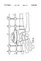
- FIG. 1ais a section through the device in accordance with the invention.
- FIG. 1bis a section through the device according to FIG. 1a showing the range of rotation of the device
- FIG. 1cis a section perpendicular to that according to FIG. 1a along line A--A;
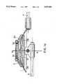
- FIG. 2is a side view of the device in accordance with the invention applied to a distal radius fracture
- FIG. 3is a side view of a modified device allowing additional translational movements
- FIG. 4is a side view of the device according to FIG. 2 with an additional cross bar.
- the device as shown in FIG. 1aconsists basically of two parts 1,2 glidingly connected to each other.
- the first partconsists of a three-dimensional shell 1 having the shape of a spherical zone with the radius R.
- the second partis a gliding element 2 consisting of a first disk 2A and a second disk 2B having an annular gliding contact area 2D and being linked together by a threaded extension 2C.
- the disks 2A and 2Bcould be provided with gliding pads to contact the shell 1, whereby at least three of such pads should be present on each side of the shell 1.
- the first disk 2Ais mounted on top of the shell 1 and the second disk 2B is mounted below on the opposite side of the shell 1.
- the threaded extension 2C of the disk 2Bpasses through the opening 12 of the shell 1 and is secured in the threaded hole 2E in the center of the first disc 2A.
- FIG. 1bshows the range of rotation ⁇ in the plane parallel to the longitudinal bars 3,4.
- the center of rotationis at C, with radius of the shell 1 marked by R.
- FIG. 1cshows a vertical section along the line A--A of FIG. 1a.
- the screw 13is used to clamp the gliding element 2 of the device to the longitudinal bar 3.
- the shell 1is attached to the extremity of the first longitudinal bar 4 and the gliding element 2 is attached to the extremity of a second longitudinal bar 3 which act as carriers for fixation means 5,10 to the bone as shown in FIG. 2.
- the shell 1 and the gliding element 2are movably arranged to each other in such a way that the free ends of said first and second longitudinal bars are extending in opposite directions as shown in FIG. 2. This results in a fixation device having a center of rotation in the center of a sphere, i.e. at a distance R from the spherical zone surface of the shell 1.
- the external fixation devicecan be mounted at the wrist by means of four Kirschner wires 5A,5B,5C,5D held by conventional external fixation clamps 10 to the longitudinal bars 3,4.
- Two Kirschner wires 5A,5Bare fixed to the second metacarpal 8 and two further Kirschner wires 5C,5D are fixed to the radius 7.
- the deviceis mounted in such a way that the spherical zone surface of the shell 1 is located approximately at a distance R from the center of rotation of the wrist joint 11.
- the external fixation deviceprovides a means of maintaining fracture alignment and distraction as marked by arrow 17, while allowing rotation of the wrist joint in all planes.
- FIG. 3shows an embodiment of the invention with an additional set of elements 14,15,16 interposed between the shell 1 and the longitudinal bar 4 which allows for free translation between them along the axes x and y.
- Thisis done e.g. by having a guiding element 15 with gliding dovetail grooves 18,19 extending at 90° to each other interposed between gliding elements 14 and 16 with matching dovetail pairs 20,21.
- Gliding elements 14 and 16may be fixed to the guiding element 15 by any type of known fixation means, e.g. fixation screws, which are not shown in the drawing.
- fixation meanse.g. fixation screws
- the sliding movability between the shell and the gliding elements of the external fixation device according to FIGS. 1 to 3can be prevented either by tightening the threaded connection 2C between the two disks 2A,2B or as shown in FIG. 4 by a third longitudinal bar 9 running parallel to the first and second longitudinal bars 3,4, to which the four Kirschner wires 5A,5B,5C,5D are fixed by additional external fixation clamps 10.
Landscapes
- Health & Medical Sciences (AREA)
- Orthopedic Medicine & Surgery (AREA)
- Life Sciences & Earth Sciences (AREA)
- Surgery (AREA)
- Biomedical Technology (AREA)
- Engineering & Computer Science (AREA)
- Nuclear Medicine, Radiotherapy & Molecular Imaging (AREA)
- Heart & Thoracic Surgery (AREA)
- Medical Informatics (AREA)
- Molecular Biology (AREA)
- Animal Behavior & Ethology (AREA)
- General Health & Medical Sciences (AREA)
- Public Health (AREA)
- Veterinary Medicine (AREA)
- Surgical Instruments (AREA)
Abstract
Description
Claims (11)
Applications Claiming Priority (2)
| Application Number | Priority Date | Filing Date | Title |
|---|---|---|---|
| CA002106777ACA2106777C (en) | 1992-08-24 | 1992-08-24 | External fixation device for osteosynthesis |
| PCT/EP1992/001936WO1994004087A1 (en) | 1992-08-24 | 1992-08-24 | External fixation device for osteosynthesis |
Publications (1)
| Publication Number | Publication Date |
|---|---|
| US5437666Atrue US5437666A (en) | 1995-08-01 |
Family
ID=8165679
Family Applications (1)
| Application Number | Title | Priority Date | Filing Date |
|---|---|---|---|
| US08/119,059Expired - LifetimeUS5437666A (en) | 1992-08-24 | 1992-08-24 | External fixation device for osteosynthesis |
Country Status (6)
| Country | Link |
|---|---|
| US (1) | US5437666A (en) |
| EP (1) | EP0610219B1 (en) |
| JP (1) | JP3380243B2 (en) |
| CA (1) | CA2106777C (en) |
| DE (1) | DE69214155T2 (en) |
| WO (1) | WO1994004087A1 (en) |
Cited By (32)
| Publication number | Priority date | Publication date | Assignee | Title |
|---|---|---|---|---|
| US5741256A (en)* | 1997-01-13 | 1998-04-21 | Synthes (U.S.A.) | Helical osteosynthetic implant |
| WO1998046156A1 (en)* | 1997-04-11 | 1998-10-22 | Keele University | Fracture reduction device |
| WO1998051227A1 (en)* | 1997-05-15 | 1998-11-19 | Wright Medical Technology, Inc. | External fixation system |
| US6010501A (en)* | 1997-12-15 | 2000-01-04 | Electro-Biology, Inc. | Method and apparatus for external fixation of small bones |
| US6203548B1 (en)* | 1997-07-07 | 2001-03-20 | Prototech As | Distraction apparatus |
| US6231576B1 (en) | 1996-12-02 | 2001-05-15 | Synthes (U.S.A.) | Flat intramedullary nail |
| US6428540B1 (en)* | 1996-11-13 | 2002-08-06 | Synthes (U.S.A.) | Device for repositioning fractured bone fragments |
| DE10124994A1 (en)* | 2001-05-22 | 2002-12-12 | Hans-Georg Gradl | Fractured bone fixture especially on wrist has first and further supports, fixture elements, and adjustable fixture element |
| US20030149429A1 (en)* | 2002-02-04 | 2003-08-07 | Joseph Ferrante | External fixation system |
| US20030149430A1 (en)* | 2002-02-04 | 2003-08-07 | Joseph Ferrante | Devices, systems, and methods for placing and positioning fixation elements in external fixation systems |
| US20030216734A1 (en)* | 2002-05-20 | 2003-11-20 | Citieffe S.R.L. | External fixation system for treating bone fractures |
| US6736818B2 (en) | 1999-11-11 | 2004-05-18 | Synthes (U.S.A.) | Radially expandable intramedullary nail |
| US20040138659A1 (en)* | 2003-01-10 | 2004-07-15 | Ed Austin | External fixation apparatus and method |
| US20040249375A1 (en)* | 2003-06-03 | 2004-12-09 | The John M. Agee Trust | External fixator for colles' fracture |
| US20050245939A1 (en)* | 2002-06-14 | 2005-11-03 | Joseph Ferrante | Device and methods for placing external fixation elements |
| US20060064087A1 (en)* | 2004-09-03 | 2006-03-23 | Ather Mirza | External fixation device for fractures |
| CN100539960C (en)* | 2007-08-16 | 2009-09-16 | 王纪亮 | Universal type fixer outside far end bone of radius |
| US20110082458A1 (en)* | 2009-10-05 | 2011-04-07 | Stryker Trauma Sa | Dynamic External Fixator And Methods For Use |
| CN101066226B (en)* | 2007-06-07 | 2011-06-29 | 深圳市第二人民医院 | A kind of fracture reduction external fixation bracket |
| US20130116692A1 (en)* | 2007-03-07 | 2013-05-09 | Wright Medical Technology, Inc. | External fixation |
| US8945128B2 (en) | 2010-08-11 | 2015-02-03 | Stryker Trauma Sa | External fixator system |
| US9101398B2 (en) | 2012-08-23 | 2015-08-11 | Stryker Trauma Sa | Bone transport external fixation frame |
| US9155561B2 (en) | 2013-03-06 | 2015-10-13 | Stryker Trauma Sa | Mini-rail external fixator |
| US9408635B2 (en) | 2013-03-15 | 2016-08-09 | Wright Medical Technology, Inc. | External fixation |
| US9717527B2 (en) | 2010-08-11 | 2017-08-01 | Stryker European Holdings I, Llc | External fixator system |
| US9770272B2 (en) | 2012-12-12 | 2017-09-26 | Wright Medical Technology, Inc. | Orthopedic compression/distraction device |
| US9962188B2 (en) | 2013-10-29 | 2018-05-08 | Cardinal Health 247. Inc. | External fixation system and methods of use |
| US10194945B2 (en) | 2013-03-15 | 2019-02-05 | DePuy Synthes Products, Inc. | External fixation system with radio frequency shielding |
| US10531896B2 (en) | 2015-08-10 | 2020-01-14 | Stryker European Holdings I, Llc | Distraction tube with wire clamp |
| US10610123B2 (en) | 2013-03-15 | 2020-04-07 | DePuy Synthes Products, Inc. | External fixation system with radio frequency shielding |
| US11141196B2 (en) | 2010-08-11 | 2021-10-12 | Stryker European Operations Holdings Llc | External fixator system |
| US11653951B2 (en)* | 2018-11-06 | 2023-05-23 | Ali Moradi | External orthopedic fixation device |
Families Citing this family (2)
| Publication number | Priority date | Publication date | Assignee | Title |
|---|---|---|---|---|
| US5571103A (en)* | 1994-10-18 | 1996-11-05 | Bailey; Kirk J. | Method for the fixation of bone |
| US5683389A (en)* | 1994-12-05 | 1997-11-04 | Smith & Nephew, Inc. | External fixator for distal radius fractures |
Citations (12)
| Publication number | Priority date | Publication date | Assignee | Title |
|---|---|---|---|---|
| US4127119A (en)* | 1976-08-09 | 1978-11-28 | Kronner Richard F | Fracture reducing and joint immobilizing apparatus |
| US4548199A (en)* | 1981-11-13 | 1985-10-22 | Agee John M | Fracture splint |
| SU1225559A1 (en)* | 1984-11-20 | 1986-04-23 | Центральный научно-исследовательский институт травматологии и ортопедии им.Н.Н.Приорова | Apparatus for restoring mobility of hip joint |
| US4604997A (en)* | 1984-02-13 | 1986-08-12 | Orthofix S.R.L. | Articulated mini external fixation device |
| US4637382A (en)* | 1982-04-27 | 1987-01-20 | Brigham & Women's Hospital | Motion-guiding load-bearing external linkage for the knee |
| EP0248138A1 (en)* | 1986-05-20 | 1987-12-09 | Jaquet Orthopedie S.A. | External dynamic bone fixation device |
| SU1380738A1 (en)* | 1986-03-31 | 1988-03-15 | Горьковский научно-исследовательский институт травматологии и ортопедии | Surgical apparatus for developing monocentric joints |
| US4895141A (en)* | 1984-04-26 | 1990-01-23 | Harrington Arthritis Research Center | Unilateral external fixation device |
| US4922896A (en)* | 1989-05-05 | 1990-05-08 | John M. Agee | Colles' fracture splint |
| US4968316A (en)* | 1988-12-12 | 1990-11-06 | Hergenroeder Patrick T | Arthroscopic ankle joint distraction method |
| EP0458486A1 (en)* | 1990-05-04 | 1991-11-27 | James Bruce Richardson | Bone fixator |
| US5160335A (en)* | 1988-12-15 | 1992-11-03 | Jaquet Orthopedie S.A. | Pin holder support |
- 1992
- 1992-08-24EPEP92917550Apatent/EP0610219B1/ennot_activeExpired - Lifetime
- 1992-08-24USUS08/119,059patent/US5437666A/ennot_activeExpired - Lifetime
- 1992-08-24CACA002106777Apatent/CA2106777C/ennot_activeExpired - Fee Related
- 1992-08-24DEDE69214155Tpatent/DE69214155T2/ennot_activeExpired - Fee Related
- 1992-08-24JPJP50274594Apatent/JP3380243B2/ennot_activeExpired - Fee Related
- 1992-08-24WOPCT/EP1992/001936patent/WO1994004087A1/enactiveIP Right Grant
Patent Citations (12)
| Publication number | Priority date | Publication date | Assignee | Title |
|---|---|---|---|---|
| US4127119A (en)* | 1976-08-09 | 1978-11-28 | Kronner Richard F | Fracture reducing and joint immobilizing apparatus |
| US4548199A (en)* | 1981-11-13 | 1985-10-22 | Agee John M | Fracture splint |
| US4637382A (en)* | 1982-04-27 | 1987-01-20 | Brigham & Women's Hospital | Motion-guiding load-bearing external linkage for the knee |
| US4604997A (en)* | 1984-02-13 | 1986-08-12 | Orthofix S.R.L. | Articulated mini external fixation device |
| US4895141A (en)* | 1984-04-26 | 1990-01-23 | Harrington Arthritis Research Center | Unilateral external fixation device |
| SU1225559A1 (en)* | 1984-11-20 | 1986-04-23 | Центральный научно-исследовательский институт травматологии и ортопедии им.Н.Н.Приорова | Apparatus for restoring mobility of hip joint |
| SU1380738A1 (en)* | 1986-03-31 | 1988-03-15 | Горьковский научно-исследовательский институт травматологии и ортопедии | Surgical apparatus for developing monocentric joints |
| EP0248138A1 (en)* | 1986-05-20 | 1987-12-09 | Jaquet Orthopedie S.A. | External dynamic bone fixation device |
| US4968316A (en)* | 1988-12-12 | 1990-11-06 | Hergenroeder Patrick T | Arthroscopic ankle joint distraction method |
| US5160335A (en)* | 1988-12-15 | 1992-11-03 | Jaquet Orthopedie S.A. | Pin holder support |
| US4922896A (en)* | 1989-05-05 | 1990-05-08 | John M. Agee | Colles' fracture splint |
| EP0458486A1 (en)* | 1990-05-04 | 1991-11-27 | James Bruce Richardson | Bone fixator |
Cited By (66)
| Publication number | Priority date | Publication date | Assignee | Title |
|---|---|---|---|---|
| US6428540B1 (en)* | 1996-11-13 | 2002-08-06 | Synthes (U.S.A.) | Device for repositioning fractured bone fragments |
| US6231576B1 (en) | 1996-12-02 | 2001-05-15 | Synthes (U.S.A.) | Flat intramedullary nail |
| US5908422A (en)* | 1997-01-13 | 1999-06-01 | Synthes (U.S.A) | Helical osteosynthetic implant |
| US5741256A (en)* | 1997-01-13 | 1998-04-21 | Synthes (U.S.A.) | Helical osteosynthetic implant |
| WO1998046156A1 (en)* | 1997-04-11 | 1998-10-22 | Keele University | Fracture reduction device |
| US6328737B1 (en) | 1997-04-11 | 2001-12-11 | Keel University | Fracture reduction device |
| WO1998051227A1 (en)* | 1997-05-15 | 1998-11-19 | Wright Medical Technology, Inc. | External fixation system |
| US5897555A (en)* | 1997-05-15 | 1999-04-27 | Wright Medical Technology, Inc. | External fixation system and method |
| US6203548B1 (en)* | 1997-07-07 | 2001-03-20 | Prototech As | Distraction apparatus |
| US6010501A (en)* | 1997-12-15 | 2000-01-04 | Electro-Biology, Inc. | Method and apparatus for external fixation of small bones |
| US6736818B2 (en) | 1999-11-11 | 2004-05-18 | Synthes (U.S.A.) | Radially expandable intramedullary nail |
| DE10124994A1 (en)* | 2001-05-22 | 2002-12-12 | Hans-Georg Gradl | Fractured bone fixture especially on wrist has first and further supports, fixture elements, and adjustable fixture element |
| DE10124994B4 (en)* | 2001-05-22 | 2004-09-16 | Gradl, Hans-Georg, Dr. med. | Device for fixing bones in the area of the wrist |
| US20030149429A1 (en)* | 2002-02-04 | 2003-08-07 | Joseph Ferrante | External fixation system |
| US20030149430A1 (en)* | 2002-02-04 | 2003-08-07 | Joseph Ferrante | Devices, systems, and methods for placing and positioning fixation elements in external fixation systems |
| US7048735B2 (en) | 2002-02-04 | 2006-05-23 | Smith & Nephew | External fixation system |
| US7887537B2 (en) | 2002-02-04 | 2011-02-15 | Smith & Nephew, Inc. | External fixation system |
| US20050119656A1 (en)* | 2002-02-04 | 2005-06-02 | Joseph Ferrante | External fixation system |
| US7004943B2 (en) | 2002-02-04 | 2006-02-28 | Smith & Nephew, Inc. | Devices, systems, and methods for placing and positioning fixation elements in external fixation systems |
| US20030216734A1 (en)* | 2002-05-20 | 2003-11-20 | Citieffe S.R.L. | External fixation system for treating bone fractures |
| US7758582B2 (en) | 2002-06-14 | 2010-07-20 | Smith & Nephew, Inc. | Device and methods for placing external fixation elements |
| US20050245939A1 (en)* | 2002-06-14 | 2005-11-03 | Joseph Ferrante | Device and methods for placing external fixation elements |
| WO2004062514A1 (en)* | 2003-01-10 | 2004-07-29 | Smith & Nephew, Inc. | External fixation apparatus |
| US20070255280A1 (en)* | 2003-01-10 | 2007-11-01 | Smith & Nephew, Inc. | External fixation apparatus and method |
| AU2003296463B2 (en)* | 2003-01-10 | 2009-09-03 | Smith & Nephew, Inc. | External fixation apparatus |
| US7608074B2 (en) | 2003-01-10 | 2009-10-27 | Smith & Nephew, Inc. | External fixation apparatus and method |
| US8382755B2 (en)* | 2003-01-10 | 2013-02-26 | Smith & Nephew, Inc. | External fixation apparatus and method |
| US20040138659A1 (en)* | 2003-01-10 | 2004-07-15 | Ed Austin | External fixation apparatus and method |
| US7291148B2 (en) | 2003-06-03 | 2007-11-06 | John M. Agee Trustee Of The John M. Agee Trust | External fixator for Colles' fracture |
| US20040249375A1 (en)* | 2003-06-03 | 2004-12-09 | The John M. Agee Trust | External fixator for colles' fracture |
| US20060064087A1 (en)* | 2004-09-03 | 2006-03-23 | Ather Mirza | External fixation device for fractures |
| US7828801B2 (en)* | 2004-09-03 | 2010-11-09 | A.M. Surgical, Inc. | External fixation device for fractures |
| US9351764B2 (en)* | 2007-03-07 | 2016-05-31 | Wright Medical Technology, Inc. | External fixation |
| US20130116692A1 (en)* | 2007-03-07 | 2013-05-09 | Wright Medical Technology, Inc. | External fixation |
| CN101066226B (en)* | 2007-06-07 | 2011-06-29 | 深圳市第二人民医院 | A kind of fracture reduction external fixation bracket |
| CN100539960C (en)* | 2007-08-16 | 2009-09-16 | 王纪亮 | Universal type fixer outside far end bone of radius |
| US9351763B2 (en) | 2009-10-05 | 2016-05-31 | Stryker European Holdings I, Llc | Dynamic external fixator and methods for use |
| US8858555B2 (en)* | 2009-10-05 | 2014-10-14 | Stryker Trauma Sa | Dynamic external fixator and methods for use |
| US8906020B2 (en) | 2009-10-05 | 2014-12-09 | Stryker Trauma Sa | Dynamic external fixator and methods for use |
| US20110082458A1 (en)* | 2009-10-05 | 2011-04-07 | Stryker Trauma Sa | Dynamic External Fixator And Methods For Use |
| US10149701B2 (en) | 2009-10-05 | 2018-12-11 | Stryker European Holdings I, Llc | Dynamic external fixator and methods for use |
| US10376285B2 (en) | 2010-08-11 | 2019-08-13 | Stryker European Holdings I, Llc | External fixator system |
| US9220533B2 (en) | 2010-08-11 | 2015-12-29 | Stryker Trauma Sa | External fixator system |
| US12035944B2 (en) | 2010-08-11 | 2024-07-16 | Stryker European Operations Holdings Llc | External fixator system |
| US10285734B2 (en) | 2010-08-11 | 2019-05-14 | Stryker European Holdings I, Llc | External fixator system |
| US11141196B2 (en) | 2010-08-11 | 2021-10-12 | Stryker European Operations Holdings Llc | External fixator system |
| US9717527B2 (en) | 2010-08-11 | 2017-08-01 | Stryker European Holdings I, Llc | External fixator system |
| US9730730B2 (en) | 2010-08-11 | 2017-08-15 | Stryker European Holdings I, Llc | External fixator system |
| US10080585B2 (en) | 2010-08-11 | 2018-09-25 | Stryker European Holdings I, Llc | External fixator system |
| US8945128B2 (en) | 2010-08-11 | 2015-02-03 | Stryker Trauma Sa | External fixator system |
| US9839445B2 (en) | 2010-08-11 | 2017-12-12 | Stryker European Holdings I, Llc | External fixator system |
| US9820775B2 (en) | 2012-08-23 | 2017-11-21 | Styker European Holdings I, LLC | Bone transport external fixation frame |
| US11090086B2 (en) | 2012-08-23 | 2021-08-17 | Stryker European Operations Holdings Llc | Bone transport external fixation frame |
| US9101398B2 (en) | 2012-08-23 | 2015-08-11 | Stryker Trauma Sa | Bone transport external fixation frame |
| US10405888B2 (en) | 2012-08-23 | 2019-09-10 | Stryker European Holdings I, Llc | Bone transport external fixation frame |
| US11744616B2 (en) | 2012-08-23 | 2023-09-05 | Stryker European Operations Holdings Llc | Bone transport external fixation frame |
| US10631900B2 (en) | 2012-12-12 | 2020-04-28 | Wright Medical Technology, Inc. | Orthopedic compression/distraction device |
| US9770272B2 (en) | 2012-12-12 | 2017-09-26 | Wright Medical Technology, Inc. | Orthopedic compression/distraction device |
| US9622781B2 (en) | 2013-03-06 | 2017-04-18 | Stryker European Holdings I, Llc | Mini-rail external fixator |
| US9155561B2 (en) | 2013-03-06 | 2015-10-13 | Stryker Trauma Sa | Mini-rail external fixator |
| US10194945B2 (en) | 2013-03-15 | 2019-02-05 | DePuy Synthes Products, Inc. | External fixation system with radio frequency shielding |
| US10610123B2 (en) | 2013-03-15 | 2020-04-07 | DePuy Synthes Products, Inc. | External fixation system with radio frequency shielding |
| US9408635B2 (en) | 2013-03-15 | 2016-08-09 | Wright Medical Technology, Inc. | External fixation |
| US9962188B2 (en) | 2013-10-29 | 2018-05-08 | Cardinal Health 247. Inc. | External fixation system and methods of use |
| US10531896B2 (en) | 2015-08-10 | 2020-01-14 | Stryker European Holdings I, Llc | Distraction tube with wire clamp |
| US11653951B2 (en)* | 2018-11-06 | 2023-05-23 | Ali Moradi | External orthopedic fixation device |
Also Published As
| Publication number | Publication date |
|---|---|
| JPH07500274A (en) | 1995-01-12 |
| EP0610219A1 (en) | 1994-08-17 |
| WO1994004087A1 (en) | 1994-03-03 |
| CA2106777C (en) | 1999-06-29 |
| DE69214155D1 (en) | 1996-10-31 |
| DE69214155T2 (en) | 1997-02-06 |
| EP0610219B1 (en) | 1996-09-25 |
| CA2106777A1 (en) | 1994-02-25 |
| JP3380243B2 (en) | 2003-02-24 |
Similar Documents
| Publication | Publication Date | Title |
|---|---|---|
| US5437666A (en) | External fixation device for osteosynthesis | |
| US4554915A (en) | Bone fixation frame | |
| US4745913A (en) | Apparatus for the stabilization of bone fractures | |
| CA1271382A (en) | Orthopedic external fixing apparatus using half rings and bars | |
| US5074866A (en) | Translation/rotation device for external bone fixation system | |
| EP0397059A2 (en) | Improved colles' fracture splint | |
| EP0140591A2 (en) | A unilateral external fixation system for small bones | |
| Vidal | External fixation: yesterday, today, and tomorrow | |
| EP1439787B1 (en) | A system for fixation of fractures comprising an elastic chassis | |
| RU2063720C1 (en) | Rod-type compression-distraction apparatus | |
| SU1581299A1 (en) | Device for bone ostheosynthesis | |
| SU1250277A1 (en) | Arrangement for reposition and fixing of bone fragments | |
| RU2015687C1 (en) | Compression-distraction system | |
| RU2207079C2 (en) | Apparatus for carrying out extrafocal fixation and reposition | |
| RU2125417C1 (en) | Device for perosseous osteosynthesis | |
| SU1616640A1 (en) | Compression-distruction apparatus | |
| SU1512583A1 (en) | Arrangement for reposition and fixing bone fragments | |
| SU1377079A1 (en) | Arrangement for treatment of diaphysical fractures | |
| RU2806051C1 (en) | Fixing structure for kirschner wires for maxillofacial osteosynthesis | |
| RU2008839C1 (en) | Apparatus for percutaneous fixation of clavicle fractures | |
| CA1317172C (en) | Apparatus for the stabilising of osseous fractures | |
| SU1090378A1 (en) | Apparatus for external perosseous osteosynthesis | |
| RU2033763C1 (en) | Method of osteosynthesis and stop for realization | |
| RU2003301C1 (en) | Apparatus for treatment of overcondyle fractures of shoulder ossa | |
| SU1457911A1 (en) | Arrangement for reposition and fixing of tubular bones |
Legal Events
| Date | Code | Title | Description |
|---|---|---|---|
| AS | Assignment | Owner name:SYNTHES (U.S.A.), PENNSYLVANIA Free format text:ASSIGNMENT OF ASSIGNORS INTEREST;ASSIGNORS:TEPIC, SLOBODAN;GOSLINGS, CAREL;REEL/FRAME:006972/0048 Effective date:19930306 | |
| STCF | Information on status: patent grant | Free format text:PATENTED CASE | |
| FPAY | Fee payment | Year of fee payment:4 | |
| FPAY | Fee payment | Year of fee payment:8 | |
| FEPP | Fee payment procedure | Free format text:PAYOR NUMBER ASSIGNED (ORIGINAL EVENT CODE: ASPN); ENTITY STATUS OF PATENT OWNER: LARGE ENTITY | |
| FPAY | Fee payment | Year of fee payment:12 | |
| AS | Assignment | Owner name:SYNTHES USA, LLC, PENNSYLVANIA Free format text:CHANGE OF NAME;ASSIGNOR:SYNTHES (U.S.A.);REEL/FRAME:022399/0008 Effective date:20081231 | |
| AS | Assignment | Owner name:SYNTHES USA, LLC, PENNSYLVANIA Free format text:CHANGE OF NAME;ASSIGNOR:SYNTHES (U.S.A.);REEL/FRAME:022826/0140 Effective date:20081223 Owner name:SYNTHES USA, LLC,PENNSYLVANIA Free format text:CHANGE OF NAME;ASSIGNOR:SYNTHES (U.S.A.);REEL/FRAME:022826/0140 Effective date:20081223 |