US5437639A - Needle protective sheath device - Google Patents
Needle protective sheath deviceDownload PDFInfo
- Publication number
- US5437639A US5437639AUS08/308,386US30838694AUS5437639AUS 5437639 AUS5437639 AUS 5437639AUS 30838694 AUS30838694 AUS 30838694AUS 5437639 AUS5437639 AUS 5437639A
- Authority
- US
- United States
- Prior art keywords
- locking means
- distal end
- needle
- distal
- proximal
- Prior art date
- Legal status (The legal status is an assumption and is not a legal conclusion. Google has not performed a legal analysis and makes no representation as to the accuracy of the status listed.)
- Expired - Fee Related
Links
Images

Classifications
- A—HUMAN NECESSITIES
- A61—MEDICAL OR VETERINARY SCIENCE; HYGIENE
- A61M—DEVICES FOR INTRODUCING MEDIA INTO, OR ONTO, THE BODY; DEVICES FOR TRANSDUCING BODY MEDIA OR FOR TAKING MEDIA FROM THE BODY; DEVICES FOR PRODUCING OR ENDING SLEEP OR STUPOR
- A61M5/00—Devices for bringing media into the body in a subcutaneous, intra-vascular or intramuscular way; Accessories therefor, e.g. filling or cleaning devices, arm-rests
- A61M5/178—Syringes
- A61M5/31—Details
- A61M5/32—Needles; Details of needles pertaining to their connection with syringe or hub; Accessories for bringing the needle into, or holding the needle on, the body; Devices for protection of needles
- A61M5/3205—Apparatus for removing or disposing of used needles or syringes, e.g. containers; Means for protection against accidental injuries from used needles
- A61M5/321—Means for protection against accidental injuries by used needles
- A61M5/3243—Means for protection against accidental injuries by used needles being axially-extensible, e.g. protective sleeves coaxially slidable on the syringe barrel
- A61M5/3271—Means for protection against accidental injuries by used needles being axially-extensible, e.g. protective sleeves coaxially slidable on the syringe barrel with guiding tracks for controlled sliding of needle protective sleeve from needle exposing to needle covering position
- A—HUMAN NECESSITIES
- A61—MEDICAL OR VETERINARY SCIENCE; HYGIENE
- A61B—DIAGNOSIS; SURGERY; IDENTIFICATION
- A61B5/00—Measuring for diagnostic purposes; Identification of persons
- A61B5/15—Devices for taking samples of blood
- A61B5/150007—Details
- A61B5/150015—Source of blood
- A61B5/15003—Source of blood for venous or arterial blood
- A—HUMAN NECESSITIES
- A61—MEDICAL OR VETERINARY SCIENCE; HYGIENE
- A61B—DIAGNOSIS; SURGERY; IDENTIFICATION
- A61B5/00—Measuring for diagnostic purposes; Identification of persons
- A61B5/15—Devices for taking samples of blood
- A61B5/150007—Details
- A61B5/150374—Details of piercing elements or protective means for preventing accidental injuries by such piercing elements
- A61B5/150534—Design of protective means for piercing elements for preventing accidental needle sticks, e.g. shields, caps, protectors, axially extensible sleeves, pivotable protective sleeves
- A61B5/150633—Protective sleeves which are axially extensible, e.g. sleeves connected to, or integrated in, the piercing or driving device; pivotable protective sleeves
- A61B5/150641—Protective sleeves which are axially extensible, e.g. sleeves connected to, or integrated in, the piercing or driving device; pivotable protective sleeves comprising means to impede repositioning of protection sleeve from covering to uncovering position
- A—HUMAN NECESSITIES
- A61—MEDICAL OR VETERINARY SCIENCE; HYGIENE
- A61B—DIAGNOSIS; SURGERY; IDENTIFICATION
- A61B5/00—Measuring for diagnostic purposes; Identification of persons
- A61B5/15—Devices for taking samples of blood
- A61B5/150007—Details
- A61B5/150732—Needle holders, for instance for holding the needle by the hub, used for example with double-ended needle and pre-evacuated tube
- A—HUMAN NECESSITIES
- A61—MEDICAL OR VETERINARY SCIENCE; HYGIENE
- A61B—DIAGNOSIS; SURGERY; IDENTIFICATION
- A61B5/00—Measuring for diagnostic purposes; Identification of persons
- A61B5/15—Devices for taking samples of blood
- A61B5/153—Devices specially adapted for taking samples of venous or arterial blood, e.g. with syringes
- A61B5/154—Devices using pre-evacuated means
- A—HUMAN NECESSITIES
- A61—MEDICAL OR VETERINARY SCIENCE; HYGIENE
- A61B—DIAGNOSIS; SURGERY; IDENTIFICATION
- A61B5/00—Measuring for diagnostic purposes; Identification of persons
- A61B5/15—Devices for taking samples of blood
- A61B5/150007—Details
- A61B5/150374—Details of piercing elements or protective means for preventing accidental injuries by such piercing elements
- A61B5/150381—Design of piercing elements
- A61B5/150389—Hollow piercing elements, e.g. canulas, needles, for piercing the skin
- A—HUMAN NECESSITIES
- A61—MEDICAL OR VETERINARY SCIENCE; HYGIENE
- A61B—DIAGNOSIS; SURGERY; IDENTIFICATION
- A61B5/00—Measuring for diagnostic purposes; Identification of persons
- A61B5/15—Devices for taking samples of blood
- A61B5/150007—Details
- A61B5/150374—Details of piercing elements or protective means for preventing accidental injuries by such piercing elements
- A61B5/150381—Design of piercing elements
- A61B5/150473—Double-ended needles, e.g. used with pre-evacuated sampling tubes
- A61B5/150496—Details of construction of hub, i.e. element used to attach the double-ended needle to a piercing device or sampling device
- A—HUMAN NECESSITIES
- A61—MEDICAL OR VETERINARY SCIENCE; HYGIENE
- A61B—DIAGNOSIS; SURGERY; IDENTIFICATION
- A61B5/00—Measuring for diagnostic purposes; Identification of persons
- A61B5/15—Devices for taking samples of blood
- A61B5/150007—Details
- A61B5/150374—Details of piercing elements or protective means for preventing accidental injuries by such piercing elements
- A61B5/150534—Design of protective means for piercing elements for preventing accidental needle sticks, e.g. shields, caps, protectors, axially extensible sleeves, pivotable protective sleeves
- A61B5/150572—Pierceable protectors, e.g. shields, caps, sleeves or films, e.g. for hygienic purposes
- A—HUMAN NECESSITIES
- A61—MEDICAL OR VETERINARY SCIENCE; HYGIENE
- A61M—DEVICES FOR INTRODUCING MEDIA INTO, OR ONTO, THE BODY; DEVICES FOR TRANSDUCING BODY MEDIA OR FOR TAKING MEDIA FROM THE BODY; DEVICES FOR PRODUCING OR ENDING SLEEP OR STUPOR
- A61M5/00—Devices for bringing media into the body in a subcutaneous, intra-vascular or intramuscular way; Accessories therefor, e.g. filling or cleaning devices, arm-rests
- A61M5/178—Syringes
- A61M5/31—Details
- A61M5/32—Needles; Details of needles pertaining to their connection with syringe or hub; Accessories for bringing the needle into, or holding the needle on, the body; Devices for protection of needles
- A61M5/3205—Apparatus for removing or disposing of used needles or syringes, e.g. containers; Means for protection against accidental injuries from used needles
- A61M5/321—Means for protection against accidental injuries by used needles
- A61M5/3243—Means for protection against accidental injuries by used needles being axially-extensible, e.g. protective sleeves coaxially slidable on the syringe barrel
- A61M5/3245—Constructional features thereof, e.g. to improve manipulation or functioning
- A61M2005/3246—Constructional features thereof, e.g. to improve manipulation or functioning being squeezably deformable for locking or unlocking purposes, e.g. with elliptical cross-section
Definitions
- This inventionrelates to needle protective sheath devices, more particularly, protective devices used to protect hypodermic and blood collecting needles.
- Needle protective sheath devicesare in wide use. They typically comprise inner and outer cylindrical members with mating locking ribs and grooves and similar locking devices. The locking ribs and grooves temporarily lock the outer protective sheath in a first mode wherein the needle is exposed and projects from the protective device. This locking position is to preclude the members from accidentally engaging their locking devices in a permanent needle protective locking position prior to use of the needle.
- the devicemay be of the type for receiving a plunger in a syringe in a hyperdermic application or a vacuum cartridge having a septum which is penetrated by a needle portion inside the bore of a receiving cylinder in a blood collecting application. A blood collecting needle portion projects beyond the cylinder. When its use is completed the outer cylinder member is axially displaced from an overlying position with the inner member to a position cantilevered from the inner member and locked into a needle protective position.
- the problem recognized by the present inventionis that the prior art devices tend to be permanently locked in the needle use mode which is intended to be temporary. This is because the locking means for the temporary mode tend to be similar in construction as the locking means for the permanent needle protective mode. Therefore, it sometimes may be relatively difficult to disengage the inner and outer cylinder members for placement into the needle protective mode.
- a needle protective sheath devicecomprises a first cylindrical member having an axially extending bore extending therethrough and terminating at distal and proximal end edges of the member, the member having an axially extending slot on opposite sides thereof so the distal end edges can be manually squeezed together.
- First locking meansare on an outer surface of the member adjacent to the distal end.
- Second locking meansare on the outer surface adjacent to the proximal end.
- a second cylindrical memberhas an axially extending bore extending therethrough and terminating at distal and proximal member ends for receiving the first member therein in nested concentric relation, the second member having third locking means at the distal end thereof releasably engaged with the first locking means with the members overlying each other in the nested relation in a first relative position, the third locking means being released from engagement with the first locking means upon the squeezing the distal end edges and for locking engagement with the second locking means in a second relative position wherein the second member extends cantilevered from the first member in a needle protective condition.
- the second memberhas at least one axially extending channel in the wall forming the bore thereof, the first member including at least one axially extending ramp engaged with the channel, the channel for guiding the ramp in the axial direction, the ramp forming fourth locking means for locking the distal edge of the first member in the axial direction.
- first and second locking meansare projections extending from the peripheral outer surface of the first member and the third locking means is at least one aperture for selectively receiving the projections.
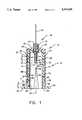
- FIG. 1is a side elevation sectional view of a blood collecting device in a needle use mode (without the blood collecting cartridge inserted) according to one embodiment of the present invention
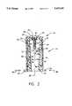
- FIG. 2is a side elevation fragmented sectional view similar to that of FIG. 1 in which the temporary locking means are disengaged prior to placement of the protective sheath in a needle protective position;
- FIG. 3is a side elevation sectional fragmented view of the device of FIG. 1 locked in a needle protective mode.
- device 10comprises an inner cylindrical thermoplastic molded member 12 and an outer cylindrical thermoplastic molded member 14.
- the membersare preferable thermoplastic but could be other materials.
- the device 10is employed for blood collecting using a vacuum cartridge (not shown) as commonly employed in this field, but could be used in a syringe implementation if desired.
- a needle assembly 16is attached to the inner member 12.
- the needle assembly 16comprises a hollow needle 18 secured to a thermoplastic connector 20.
- the connector 20has threads 22.
- the needle 18has a portion 24 which extends beyond the connector 20.
- a soft protective rubber cover 26is secured to connector 20 and extends over the needle portion 24. When the septurn of a blood collecting cartridge is forced against the cover 26, the needle portion 24 penetrates the cover 26 and the cartridge septurn in conventional fashion to engage the bore of the cartridge.
- Inner member 12comprises a circular cylindrical sleeve 28 having a bore extending along and concentric with longitudinal axis 29.
- the sleeve 28has outwardly radially extending tabs 30 and 32 at distal edge 34 relative to the needle 18.
- a pair of like circular radially outwardly extending aligned projections 36 and 38project from the outer periphery surface of the sleeve 28 in a region adjacent to the distal end at edge 34. While two projections are shown more or fewer may be provided in the alternative. In a further alternative the projections may comprise circumferential ribs (not shown).
- a further pair of like circular cylindrical projections 40 and 42extend radially outwardly from the outer periphery surface of the sleeve 28. The projections 40 and 42 are shorter in length than projections 36 and 38 for reasons to be explained.
- the projections 40 and 42are adjacent the end of the sleeve opposite distal edge 34 and are proximal the needle 18.
- a pair of ramps 44 and 46 of like dimensionsproject from the outer surface of the sleeve 28 axially spaced toward the distal end relative to the projections 40 and 42.
- the rampsincline radially outwardly as they approach the projections 40 and 42 toward the proximal end of the sleeve 28.
- the rampsextend radially outwardly about the same distance as the projections 40 and 42.
- the projections 40 and 42are spaced from the respective corresponding ramps 44 and 46 a distance d" which is preferably about the same spacing d" as the projections 36 and 38 from respective tabs 32 and 34.
- the ramps 44 and 46each have a shoulder 44'0 and 46' respectively which is normal to the axis 29 and parallel to the sides of projections 40 and 42 defining respective annular groove segments 50 and 52 therebetween.
- a pair of tapered slots 54are in opposite sides of the sleeve 28 medially between the projections 36 and 38.
- the slots 54medially along the axis of the sleeve 28 from a circular aperture 56 to distal edge 34 of member 12.
- the slots 54taper from a narrow spacing at aperture 56 to a wider spacing at edge 34.
- the proximal end of the member 12has a reduced cross section area threaded opening 60. Opening 60 receives the threads 22 of connector 20 for attaching the needle 18 to the proximal end of the member 12.
- the needle 18 boreis in communication with the bore of the cover 26 and thus the bore of sleeve 28 when portion 24 penetrates the cover 26. Not shown is a temporary protective cover for the needle 18 prior to its attachment to the member 12.
- the outer member 14has a bore 62 which is closely received over the outer surface of the inner member sleeve 28.
- a pair of like circular cylindrical diametrically opposite holes 64 and 66closely receive respective projections 36 and 36 When axially aligned therewith as shown in FIG. 1.
- Spaced distance d' from holes 64 and 66are respective ramps 68 and 70 which terminate in longitudinally axially extending channels 72 and 74, respectively.
- Channel 72receives ramp 44 and projection 40 and channel 74 receives ramp 46 and projection 42.
- the channelsaxially guide the respective ramps and projections therein.
- the proximal end of the cylinder 14 adjacent to needle 18terminates in a reduced diameter opening 76 for closely receiving connector 20.
- the member 14has a spout-like projecting end 78 forming opening 76.
- the cylinder member 14has a portion 80 between hole 64 and its distal edge at tab 32 and a portion 82 between hole 66 and the distal edge at tab 30.
- Portions 80 and 82have an axial extent parallel to axis 29 distance d".
- Distance d"is arranged to be such that portion 80 of the outer member will fit in the space between projection 40 and shoulder 44' of ramp 44 and member 14 portion 82 will fit in the space between projection 42 and shoulder 46' of ramp 46. In this latter position the portions 80 and. 82 are axially locked in place in the needle protective mode of FIG. 3.
- the needle 18is assembled to the inner member 12 via connector 20.
- the outer member 14is locked to the inner member as shown with the distal ends of the inner and outer members overlying one another and with the proximal ends overlying one another.
- the lockingoccurs with the projection 36 engaged with hole 64 and the projection 38 engaged with hole 66.
- the needle 18extends from the concentric overlying members 12 and 14.
- a cartridge(not shown) is inserted in the bore of the two combined members with the septurn of the cartridge penetrated by needle portion 24.
- the needle 16is inserted for blood collection and when done, the cartridge is removed from the members 12 and 14.
- the tabs 30 and 32are squeezed together in the direction of respective arrows 84 and 86 until the edges of the slot 54 abut as shown. At this time the projections 36 and 38 are disengaged from the holes 64 and 66.
- the outer member 14is slid axially in direction 88. In so sliding, the channels 72 and 74 guide the ramps 44 and 46 until they engage ramps 68 and 70 spreading the sides of the outer member 14 apart. The member 14 is further axially slid in direction 88 until the portions 80 and 82 snap into the groove segments 50 and 52 and the projections 40 and 42 engage the holes 64 and 66.
- the projections, holes and rampsmay be placed on reversed respective members according to a given implementation. Also the projections and holes may be replaced by ribs and grooves. Other modifications may be made by one of ordinary skill. It is intended that the detailed description be illustrative and not limiting. The scope of the invention is as defined in the appended claims.
Landscapes
- Health & Medical Sciences (AREA)
- Life Sciences & Earth Sciences (AREA)
- Engineering & Computer Science (AREA)
- Animal Behavior & Ethology (AREA)
- Hematology (AREA)
- Veterinary Medicine (AREA)
- Public Health (AREA)
- Biomedical Technology (AREA)
- Heart & Thoracic Surgery (AREA)
- General Health & Medical Sciences (AREA)
- Pathology (AREA)
- Surgery (AREA)
- Molecular Biology (AREA)
- Medical Informatics (AREA)
- Biophysics (AREA)
- Physics & Mathematics (AREA)
- Environmental & Geological Engineering (AREA)
- Vascular Medicine (AREA)
- Anesthesiology (AREA)
- Infusion, Injection, And Reservoir Apparatuses (AREA)
Abstract
Description
This invention relates to needle protective sheath devices, more particularly, protective devices used to protect hypodermic and blood collecting needles.
Needle protective sheath devices are in wide use. They typically comprise inner and outer cylindrical members with mating locking ribs and grooves and similar locking devices. The locking ribs and grooves temporarily lock the outer protective sheath in a first mode wherein the needle is exposed and projects from the protective device. This locking position is to preclude the members from accidentally engaging their locking devices in a permanent needle protective locking position prior to use of the needle. The device may be of the type for receiving a plunger in a syringe in a hyperdermic application or a vacuum cartridge having a septum which is penetrated by a needle portion inside the bore of a receiving cylinder in a blood collecting application. A blood collecting needle portion projects beyond the cylinder. When its use is completed the outer cylinder member is axially displaced from an overlying position with the inner member to a position cantilevered from the inner member and locked into a needle protective position.
The problem recognized by the present invention is that the prior art devices tend to be permanently locked in the needle use mode which is intended to be temporary. This is because the locking means for the temporary mode tend to be similar in construction as the locking means for the permanent needle protective mode. Therefore, it sometimes may be relatively difficult to disengage the inner and outer cylinder members for placement into the needle protective mode.
In accordance with an embodiment of the present invention, a needle protective sheath device comprises a first cylindrical member having an axially extending bore extending therethrough and terminating at distal and proximal end edges of the member, the member having an axially extending slot on opposite sides thereof so the distal end edges can be manually squeezed together. First locking means are on an outer surface of the member adjacent to the distal end. Second locking means are on the outer surface adjacent to the proximal end.
A second cylindrical member has an axially extending bore extending therethrough and terminating at distal and proximal member ends for receiving the first member therein in nested concentric relation, the second member having third locking means at the distal end thereof releasably engaged with the first locking means with the members overlying each other in the nested relation in a first relative position, the third locking means being released from engagement with the first locking means upon the squeezing the distal end edges and for locking engagement with the second locking means in a second relative position wherein the second member extends cantilevered from the first member in a needle protective condition.
In a further embodiment, the second member has at least one axially extending channel in the wall forming the bore thereof, the first member including at least one axially extending ramp engaged with the channel, the channel for guiding the ramp in the axial direction, the ramp forming fourth locking means for locking the distal edge of the first member in the axial direction.
In a still further embodiment, the first and second locking means are projections extending from the peripheral outer surface of the first member and the third locking means is at least one aperture for selectively receiving the projections.
FIG. 1 is a side elevation sectional view of a blood collecting device in a needle use mode (without the blood collecting cartridge inserted) according to one embodiment of the present invention;
FIG. 2 is a side elevation fragmented sectional view similar to that of FIG. 1 in which the temporary locking means are disengaged prior to placement of the protective sheath in a needle protective position; and
FIG. 3 is a side elevation sectional fragmented view of the device of FIG. 1 locked in a needle protective mode.
In FIG. 1,device 10 comprises an inner cylindrical thermoplastic moldedmember 12 and an outer cylindrical thermoplastic moldedmember 14. The members are preferable thermoplastic but could be other materials. In this embodiment thedevice 10 is employed for blood collecting using a vacuum cartridge (not shown) as commonly employed in this field, but could be used in a syringe implementation if desired. Aneedle assembly 16 is attached to theinner member 12.
Theneedle assembly 16 comprises ahollow needle 18 secured to athermoplastic connector 20. Theconnector 20 hasthreads 22. Theneedle 18 has aportion 24 which extends beyond theconnector 20. A softprotective rubber cover 26 is secured toconnector 20 and extends over theneedle portion 24. When the septurn of a blood collecting cartridge is forced against thecover 26, theneedle portion 24 penetrates thecover 26 and the cartridge septurn in conventional fashion to engage the bore of the cartridge.
A pair oframps sleeve 28 axially spaced toward the distal end relative to theprojections projections sleeve 28. The ramps extend radially outwardly about the same distance as theprojections projections corresponding ramps 44 and 46 a distance d" which is preferably about the same spacing d" as theprojections respective tabs ramps axis 29 and parallel to the sides ofprojections annular groove segments
A pair of tapered slots 54 (one being shown) are in opposite sides of thesleeve 28 medially between theprojections slots 54 medially along the axis of thesleeve 28 from acircular aperture 56 to distaledge 34 ofmember 12. Theslots 54 taper from a narrow spacing ataperture 56 to a wider spacing atedge 34.
The proximal end of themember 12 has a reduced cross section area threadedopening 60.Opening 60 receives thethreads 22 ofconnector 20 for attaching theneedle 18 to the proximal end of themember 12. Theneedle 18 bore is in communication with the bore of thecover 26 and thus the bore ofsleeve 28 whenportion 24 penetrates thecover 26. Not shown is a temporary protective cover for theneedle 18 prior to its attachment to themember 12.
Theouter member 14 has abore 62 which is closely received over the outer surface of theinner member sleeve 28. A pair of like circular cylindrical diametrically oppositeholes respective projections holes respective ramps channels ramp 44 andprojection 40 andchannel 74 receivesramp 46 andprojection 42. The channels axially guide the respective ramps and projections therein.
The proximal end of thecylinder 14 adjacent toneedle 18 terminates in a reduced diameter opening 76 for closely receivingconnector 20. Also, themember 14 has a spout-like projectingend 78 forming opening 76. Thecylinder member 14 has aportion 80 betweenhole 64 and its distal edge attab 32 and aportion 82 betweenhole 66 and the distal edge attab 30.Portions axis 29 distance d". Distance d" is arranged to be such thatportion 80 of the outer member will fit in the space betweenprojection 40 and shoulder 44' oframp 44 andmember 14portion 82 will fit in the space betweenprojection 42 and shoulder 46' oframp 46. In this latter position theportions 80 and. 82 are axially locked in place in the needle protective mode of FIG. 3.
In operation, in FIG. 1, theneedle 18 is assembled to theinner member 12 viaconnector 20. At this time theouter member 14 is locked to the inner member as shown with the distal ends of the inner and outer members overlying one another and with the proximal ends overlying one another. The locking occurs with theprojection 36 engaged withhole 64 and theprojection 38 engaged withhole 66. In this needle use mode theneedle 18 extends from the concentric overlyingmembers needle portion 24. Theneedle 16 is inserted for blood collection and when done, the cartridge is removed from themembers
In FIG. 2, thetabs respective arrows 84 and 86 until the edges of theslot 54 abut as shown. At this time theprojections holes outer member 14 is slid axially indirection 88. In so sliding, thechannels ramps ramps outer member 14 apart. Themember 14 is further axially slid indirection 88 until theportions groove segments projections holes ramps ramps outer member 14 to guide theprojections holes member 14 distal end over theprojections
The projections, holes and ramps may be placed on reversed respective members according to a given implementation. Also the projections and holes may be replaced by ribs and grooves. Other modifications may be made by one of ordinary skill. It is intended that the detailed description be illustrative and not limiting. The scope of the invention is as defined in the appended claims.
Claims (16)
1. A needle protective sheath device comprising:
a first cylindrical member having a first cylindrical cavity defining a longitudinal axis, said member having proximal and distal ends, said member having first and second openings on and extending radially transverse the axis in communication with the cavity on the respective distal and proximal ends, the second opening on the proximal end being restricted in transverse dimension with respect to the first opening on the distal end, the member including means at the proximal end opening for securing a needle thereto in communication with the cavity, the secured needle extending axially beyond the first member proximal end, the member including finger gripping means on the distal end, said member having a pair of opposed axially extending slits in communication with the distal end arranged such that opposing sides of the distal end can be squeezed together from a normally spaced apart position to a compressed position;
first locking means on the member outer surface external the cavity on each said opposing sides adjacent to said distal end;
second locking means on the member outer surface external the cavity adjacent to said proximal end;
a second cylindrical member having a second cylindrical cavity defining a second longitudinal axis, said second member having proximal and distal ends, said second member having third and fourth openings on and extending radially transverse the second axis in communication with the second cavity at the respective distal and proximal ends, the fourth opening on the proximal end being restricted in transverse dimension with respect to the third opening on the distal end, said second cavity for axially receiving the first member through the third opening with the first and second members in nested concentric relation in a first axial relative position with the members overlying one another with their respective proximal and distal ends adjacent to each other and in a second extended position wherein the second member distal end is adjacent to the first member proximal end so the second member proximal end extends beyond the first member for protecting the extended needle; and
third locking means on the second member at the second member distal end for selectively engaging the first and second locking means in accordance with the axial relative position of the first and second members wherein in the first axial position the first locking means are disengaged from the third locking means by said squeezing said opposing sides.
2. The device of claim 1 wherein the slits are tapered to a wider slit opening at the distal end of the second member.
3. The device of claim 2 wherein the slits remote the distal end terminate in a circular opening.
4. The device of claim 1 wherein the first and second locking means are circumferentially spaced projections extending radially outwardly from the first member outer surface and the third locking means comprises apertures for selectively receiving the projections for axially locking the members together in the first and second positions.
5. The device of claim 4 further including ramp means including fourth locking means on the first member outer surface facing the second locking means in axial spaced relation, the projections forming the first member second locking means being axially adjacent to the proximal end relative to the ramp means, the axial space between the fourth locking means and second locking means for receiving the distal end portion of the first member between the first member end edge and the first locking means.
6. The device of claim 1 further including the needle secured to the first member, the needle comprising first and second needles in which one needle protrudes into the first cavity, the first cavity being dimensioned to receive a vacuum cartridge including a septurn to be penetrated by the one needle.
7. The device of claim 6 further including said cartridge assembled to said members and one needle.
8. A needle protective sheath device comprising:
a first cylindrical member having a first cylindrical cavity defining a longitudinal axis, said member having proximal and distal ends, said member having first and second openings on and extending radially transverse the axis in communication with the cavity on the respective distal and proximal ends, the member including connection means at the proximal end opening for securing a hollow needle thereto in communication with the cavity, one end of the needle extending axially beyond the first member proximal end and the other end into said cavity, said member having a pair of opposed axially extending slits in communication with the distal end arranged such that opposing sides of the distal end can be squeezed together at the distal end from a normally spaced apart position to a compressed position;
first locking means on the member outer surface external the cavity on each said opposing sides adjacent to said distal end;
second locking means on the member outer surface external the cavity adjacent to said proximal end;
a second cylindrical member having a second cylindrical cavity defining a second longitudinal axis, said second member having proximal and distal ends, said second member having third and fourth openings on and extending radially transverse the second axis in communication with the second cavity at the respective distal and proximal ends, said second cavity for axially receiving the first member through the third opening with the first and second members in nested concentric relation in a first axial relative position with the members overlying one another with their respective proximal and distal ends adjacent to each other and in a second extended position wherein the second member distal end overlies the first member proximal end so the second member proximal end extends beyond the first member for protecting the extended needle; and
third locking means on the second member at the second member distal end for selectively engaging the first and second locking means in accordance with the axial relative position of the first and second members wherein in the first axial position the first locking means are disengaged from the third locking means by said squeezing said opposing sides.
9. The device of claim 8 wherein the second and fourth openings are of restricted transverse dimension relative to the first and third openings, respectively, such that the first member can not pass through the fourth opening.
10. The device of claim 8 wherein the first and second locking means are circular projections projecting from the first member outer surface and the third and fourth locking means are circular apertures.
11. The device of claim 10 wherein the second member distal end terminates in an edge, said device further including ramp means on the first member outer surface adjacent to the second locking means and forming a fourth locking means between the first and second locking means for engaging the distal edge of the second member.
12. The device of claim 11 wherein the ramp means comprises a plurality of circumferentially spaced axially extending ramps which incline radially away from the first axis in a direction toward to the proximal end, the second member having a like plurality of channels each engaged with a different corresponding ramp.
13. A needle protective sheath device comprising:
a first cylindrical member having an axially extending bore extending therethrough and terminating at distal and proximal end edges of the member, said member having an axially extending slot on opposite sides thereof so the distal end edges can be manually squeezed together;
first locking means on an outer surface of the member adjacent to the distal end;
second locking means on the outer surface adjacent to the proximal end; and
a second cylindrical member having an axially extending bore extending therethrough and terminating at distal and proximal member ends for receiving the first member therein in nested concentric relation, said second member having third locking means at the distal end thereof releasably engaged with the first locking means with said members overlying each other in said nested relation in a first relative position, said third locking means being released from engagement with the first locking means upon said squeezing said distal end edges and for locking engagement with the second locking means in a second relative position wherein the second member extends cantilevered from the first member in a needle protective condition.
14. The device of claim 13 wherein the second member has at least one axially extending channel in the wall forming the bore thereof, the first member including at least one axially extending ramp engaged with the channel, said channel for guiding the ramp in the axial direction, said ramp forming fourth locking means for locking said distal edge of the first member in the axial direction.
15. The device of claim 14 wherein the first and second locking means are projections extending from the peripheral outer surface of the first member and the third locking means is at least one aperture for selectively receiving said projections.
16. The device of claim 15 wherein the projections are circular cylinders and the at least one aperture is circular cylindrical, said channel and ramp for aligning the projections with the at least one aperture.
Priority Applications (1)
| Application Number | Priority Date | Filing Date | Title |
|---|---|---|---|
| US08/308,386US5437639A (en) | 1994-09-19 | 1994-09-19 | Needle protective sheath device |
Applications Claiming Priority (1)
| Application Number | Priority Date | Filing Date | Title |
|---|---|---|---|
| US08/308,386US5437639A (en) | 1994-09-19 | 1994-09-19 | Needle protective sheath device |
Publications (1)
| Publication Number | Publication Date |
|---|---|
| US5437639Atrue US5437639A (en) | 1995-08-01 |
Family
ID=23193786
Family Applications (1)
| Application Number | Title | Priority Date | Filing Date |
|---|---|---|---|
| US08/308,386Expired - Fee RelatedUS5437639A (en) | 1994-09-19 | 1994-09-19 | Needle protective sheath device |
Country Status (1)
| Country | Link |
|---|---|
| US (1) | US5437639A (en) |
Cited By (24)
| Publication number | Priority date | Publication date | Assignee | Title |
|---|---|---|---|---|
| US5810398A (en)* | 1992-10-02 | 1998-09-22 | Pall Corporation | Fluid delivery systems and methods and assemblies for making connections |
| US5868433A (en)* | 1992-10-02 | 1999-02-09 | Pall Corporation | Connector assembly |
| FR2778094A1 (en)* | 1998-04-29 | 1999-11-05 | Meddevice | Syringe for blood withdrawal |
| US6210374B1 (en)* | 2000-04-20 | 2001-04-03 | Robert Malencheck | Needle protective sheath device |
| US6280401B1 (en)* | 1993-08-23 | 2001-08-28 | Sakharam D. Mahurkar | Hypodermic needle assembly |
| US6471677B2 (en) | 2000-04-06 | 2002-10-29 | Gem Plastics, Inc. | Fluid collection device with protective shield |
| US6475194B2 (en) | 2000-04-05 | 2002-11-05 | Gem Plastics, Inc. | Safety syringe |
| US20030004437A1 (en)* | 2001-06-20 | 2003-01-02 | Collins Margie M. | Blood collection safety device |
| US6527742B1 (en) | 2001-11-14 | 2003-03-04 | Robert C. Malenchek | Safety syringe |
| US6540732B1 (en)* | 1998-12-15 | 2003-04-01 | Mdc Investment Holdings, Inc. | Fluid collection device with captured retractable needle |
| USD476742S1 (en) | 2002-07-22 | 2003-07-01 | Becton, Dickinson And Company | Needle holder |
| WO2003082385A1 (en)* | 2002-03-27 | 2003-10-09 | Safety Syringes, Inc. | Syringe with integral safety system |
| US6655655B1 (en) | 1997-05-09 | 2003-12-02 | Pall Corporation | Connector assemblies, fluid systems, and methods for making a connection |
| US20040204678A1 (en)* | 2000-01-27 | 2004-10-14 | Afra Design Pty. Limited. | Single-use syringe |
| US6811547B2 (en) | 2002-07-22 | 2004-11-02 | Becton, Dickinson & Company | Needle shielding assembly |
| US20040230158A1 (en)* | 2003-05-13 | 2004-11-18 | Robert Malenchek | Adaptor for converting a non-safety syringe into a safety syringe |
| US20050038392A1 (en)* | 2003-08-11 | 2005-02-17 | Becton, Dickinson And Company | Medication delivery pen assembly with needle locking safety shield |
| USD641078S1 (en) | 2008-12-29 | 2011-07-05 | Ucb Pharma, S.A. | Medical syringe with needle tip cap |
| US20110166475A1 (en)* | 2007-03-07 | 2011-07-07 | Becton, Dickinson And Company | Safety Blood Collection Assembly with Indicator |
| USD660958S1 (en) | 2009-07-20 | 2012-05-29 | Ucb Pharma, S.A. | Device for administering medication |
| US8372044B2 (en) | 2005-05-20 | 2013-02-12 | Safety Syringes, Inc. | Syringe with needle guard injection device |
| US8454059B2 (en) | 2010-09-13 | 2013-06-04 | Pall Corporation | Connector assemblies, fluid systems including connector assemblies, and procedures for making fluid connections |
| US8579866B2 (en) | 2008-01-11 | 2013-11-12 | Ucb Pharma, S.A. | Systems and methods for administering medication |
| US8945067B2 (en) | 2008-07-18 | 2015-02-03 | Ucb Pharma, S.A. | Systems for administering medication |
Citations (4)
| Publication number | Priority date | Publication date | Assignee | Title |
|---|---|---|---|---|
| US4840185A (en)* | 1988-02-17 | 1989-06-20 | Manuel Hernandez | Blood sampling device with shield |
| US4915702A (en)* | 1987-04-27 | 1990-04-10 | Habley Medical Technology Of California | Shielded safety syringe |
| US5067490A (en)* | 1988-01-05 | 1991-11-26 | Habley Medical Technology Corporation | Single use, safety blood collecting device |
| US5356392A (en)* | 1990-05-09 | 1994-10-18 | Safety Syringes, Inc. | Shielded blood collection tube holder |
- 1994
- 1994-09-19USUS08/308,386patent/US5437639A/ennot_activeExpired - Fee Related
Patent Citations (4)
| Publication number | Priority date | Publication date | Assignee | Title |
|---|---|---|---|---|
| US4915702A (en)* | 1987-04-27 | 1990-04-10 | Habley Medical Technology Of California | Shielded safety syringe |
| US5067490A (en)* | 1988-01-05 | 1991-11-26 | Habley Medical Technology Corporation | Single use, safety blood collecting device |
| US4840185A (en)* | 1988-02-17 | 1989-06-20 | Manuel Hernandez | Blood sampling device with shield |
| US5356392A (en)* | 1990-05-09 | 1994-10-18 | Safety Syringes, Inc. | Shielded blood collection tube holder |
Cited By (49)
| Publication number | Priority date | Publication date | Assignee | Title |
|---|---|---|---|---|
| US5868433A (en)* | 1992-10-02 | 1999-02-09 | Pall Corporation | Connector assembly |
| US6536805B2 (en) | 1992-10-02 | 2003-03-25 | Pall Corporation | Fluid delivery systems and methods and assemblies for making connections |
| US6341802B1 (en) | 1992-10-02 | 2002-01-29 | Pall Corporation | Fluid delivery systems and methods and assemblies for making connections |
| US5810398A (en)* | 1992-10-02 | 1998-09-22 | Pall Corporation | Fluid delivery systems and methods and assemblies for making connections |
| US6500129B1 (en)* | 1993-08-23 | 2002-12-31 | Sakharam D. Mahurkar | Hypodermic needle assembly |
| US6280401B1 (en)* | 1993-08-23 | 2001-08-28 | Sakharam D. Mahurkar | Hypodermic needle assembly |
| US6655655B1 (en) | 1997-05-09 | 2003-12-02 | Pall Corporation | Connector assemblies, fluid systems, and methods for making a connection |
| FR2778094A1 (en)* | 1998-04-29 | 1999-11-05 | Meddevice | Syringe for blood withdrawal |
| US7097633B2 (en) | 1998-12-15 | 2006-08-29 | Mdc Investment Holdings, Inc. | Fluid collection device with captured retractable needle |
| US6540732B1 (en)* | 1998-12-15 | 2003-04-01 | Mdc Investment Holdings, Inc. | Fluid collection device with captured retractable needle |
| US20040078025A1 (en)* | 1998-12-15 | 2004-04-22 | Botich Michael J. | Fluid collection device with captured retractable needle |
| US20040204678A1 (en)* | 2000-01-27 | 2004-10-14 | Afra Design Pty. Limited. | Single-use syringe |
| US6997901B2 (en) | 2000-01-27 | 2006-02-14 | Biomd Limited | Single-use syringe |
| US6475194B2 (en) | 2000-04-05 | 2002-11-05 | Gem Plastics, Inc. | Safety syringe |
| US6471677B2 (en) | 2000-04-06 | 2002-10-29 | Gem Plastics, Inc. | Fluid collection device with protective shield |
| US6210374B1 (en)* | 2000-04-20 | 2001-04-03 | Robert Malencheck | Needle protective sheath device |
| US6814707B2 (en)* | 2001-06-20 | 2004-11-09 | Margie M. Collins | Blood collection safety device |
| US20030004437A1 (en)* | 2001-06-20 | 2003-01-02 | Collins Margie M. | Blood collection safety device |
| US6527742B1 (en) | 2001-11-14 | 2003-03-04 | Robert C. Malenchek | Safety syringe |
| WO2003082385A1 (en)* | 2002-03-27 | 2003-10-09 | Safety Syringes, Inc. | Syringe with integral safety system |
| US20050020985A1 (en)* | 2002-03-27 | 2005-01-27 | Safety Syringes, Inc. | Syringe with integral safety system |
| US20050038393A1 (en)* | 2002-03-27 | 2005-02-17 | Safety Syringes, Inc. | Syringe with integral safety system |
| USD476742S1 (en) | 2002-07-22 | 2003-07-01 | Becton, Dickinson And Company | Needle holder |
| US6811547B2 (en) | 2002-07-22 | 2004-11-02 | Becton, Dickinson & Company | Needle shielding assembly |
| US6926697B2 (en) | 2003-05-13 | 2005-08-09 | Robert Malenchek | Adaptor for converting a non-safety syringe into a safety syringe |
| US20040230158A1 (en)* | 2003-05-13 | 2004-11-18 | Robert Malenchek | Adaptor for converting a non-safety syringe into a safety syringe |
| US20050038392A1 (en)* | 2003-08-11 | 2005-02-17 | Becton, Dickinson And Company | Medication delivery pen assembly with needle locking safety shield |
| US8932264B2 (en)* | 2003-08-11 | 2015-01-13 | Becton, Dickinson And Company | Medication delivery pen assembly with needle locking safety shield |
| US8372044B2 (en) | 2005-05-20 | 2013-02-12 | Safety Syringes, Inc. | Syringe with needle guard injection device |
| US11020033B2 (en) | 2007-03-07 | 2021-06-01 | Becton, Dickinson And Company | Safety blood collection assembly with indicator |
| US20110166475A1 (en)* | 2007-03-07 | 2011-07-07 | Becton, Dickinson And Company | Safety Blood Collection Assembly with Indicator |
| US20110166476A1 (en)* | 2007-03-07 | 2011-07-07 | Becton, Dickinson And Company | Safety Blood Collection Assembly with Indicator |
| US10588558B2 (en)* | 2007-03-07 | 2020-03-17 | Becton, Dickinson And Company | Safety blood collection assembly with indicator |
| US10349880B2 (en) | 2007-03-07 | 2019-07-16 | Becton, Dickinson And Company | Safety blood collection assembly with indicator |
| US20170251966A1 (en)* | 2007-03-07 | 2017-09-07 | Becton, Dickinson And Company | Safety Blood Collection Assembly with Indicator |
| US9687184B2 (en)* | 2007-03-07 | 2017-06-27 | Becton, Dickinson And Company | Safety blood collection assembly with indicator |
| US9271668B2 (en)* | 2007-03-07 | 2016-03-01 | Becton, Dickinson And Company | Safety blood collection assembly with indicator |
| US8579866B2 (en) | 2008-01-11 | 2013-11-12 | Ucb Pharma, S.A. | Systems and methods for administering medication |
| US9901686B2 (en) | 2008-01-11 | 2018-02-27 | Ucb Biopharma Sprl | Systems and methods for administering medication |
| US10661023B2 (en) | 2008-01-11 | 2020-05-26 | Ucb Bioparma Sprl | Systems and methods for administering medication |
| US8945067B2 (en) | 2008-07-18 | 2015-02-03 | Ucb Pharma, S.A. | Systems for administering medication |
| US9333305B2 (en) | 2008-07-18 | 2016-05-10 | Ucb Biopharma Sprl | Systems for automatically administering medication |
| USD661389S1 (en) | 2008-12-29 | 2012-06-05 | Ucb Pharma, S.A. | Syringe handle for a medication administration device |
| USD653336S1 (en) | 2008-12-29 | 2012-01-31 | Ucb Pharma, S.A. | Needle tip cap connector |
| USD649632S1 (en) | 2008-12-29 | 2011-11-29 | Ucb Pharma, S.A. | Handle for a medication administration device |
| USD641078S1 (en) | 2008-12-29 | 2011-07-05 | Ucb Pharma, S.A. | Medical syringe with needle tip cap |
| USD676552S1 (en) | 2009-07-20 | 2013-02-19 | Ucb Pharma, S.A. | Needle cap for a medication administration device |
| USD660958S1 (en) | 2009-07-20 | 2012-05-29 | Ucb Pharma, S.A. | Device for administering medication |
| US8454059B2 (en) | 2010-09-13 | 2013-06-04 | Pall Corporation | Connector assemblies, fluid systems including connector assemblies, and procedures for making fluid connections |
Similar Documents
| Publication | Publication Date | Title |
|---|---|---|
| US5437639A (en) | Needle protective sheath device | |
| EP0602883B1 (en) | Syringe having needle isolation features | |
| US5980494A (en) | Safety syringe | |
| US6251095B1 (en) | Safety syringe with retractable standard needles | |
| US5704919A (en) | Intravenous cannula assembly | |
| EP0573947B1 (en) | A medical device with a lockable needle shield | |
| US20010037089A1 (en) | Fluid collection device with protective shield | |
| EP0901391B1 (en) | Safety syringe | |
| US5669887A (en) | Retractable non-reusable needle | |
| CA2584106C (en) | Safety medical syringe with retractable needle | |
| US6083199A (en) | Retractable syringe | |
| US6093170A (en) | Structure safety syringe | |
| CA2453972C (en) | An automatically retractable safety syringe | |
| US6821266B2 (en) | Syringe | |
| US6210374B1 (en) | Needle protective sheath device | |
| PL196064B1 (en) | Disposable injection device | |
| EP0855194B1 (en) | Shieldable syringe assembly | |
| EP1684832A1 (en) | Safety needle | |
| WO1992005818A1 (en) | Safety syringe with retractable needle | |
| IL98250A (en) | Safety needle container | |
| US6979314B2 (en) | Safety syringe | |
| US20050015058A1 (en) | Safety system for a blood collection device | |
| US5947936A (en) | Syringe with spring biased needle cover | |
| US5947933A (en) | Syringe having safety shield | |
| US20160128616A1 (en) | Retractable fluid collection device |
Legal Events
| Date | Code | Title | Description |
|---|---|---|---|
| FEPP | Fee payment procedure | Free format text:PAYOR NUMBER ASSIGNED (ORIGINAL EVENT CODE: ASPN); ENTITY STATUS OF PATENT OWNER: SMALL ENTITY | |
| FPAY | Fee payment | Year of fee payment:4 | |
| FPAY | Fee payment | Year of fee payment:8 | |
| REMI | Maintenance fee reminder mailed | ||
| AS | Assignment | Owner name:FINANCIAL FEDERAL CREDIT INC., TEXAS Free format text:ASSIGNMENT OF ASSIGNORS INTEREST;ASSIGNOR:MEDISAFE GUARD PRODUCTS, INC;REEL/FRAME:016446/0859 Effective date:20050315 | |
| REMI | Maintenance fee reminder mailed | ||
| AS | Assignment | Owner name:U.S.SAFETY SYRINGES CO., INC., CALIFORNIA Free format text:ASSIGNMENT OF ASSIGNORS INTEREST;ASSIGNOR:FINANCIAL FEDERAL CREDIT, INC.;REEL/FRAME:019304/0272 Effective date:20060208 | |
| LAPS | Lapse for failure to pay maintenance fees | ||
| STCH | Information on status: patent discontinuation | Free format text:PATENT EXPIRED DUE TO NONPAYMENT OF MAINTENANCE FEES UNDER 37 CFR 1.362 | |
| FP | Lapsed due to failure to pay maintenance fee | Effective date:20070801 |