US5437619A - Range-of-motion splint with eccentric spring - Google Patents
Range-of-motion splint with eccentric springDownload PDFInfo
- Publication number
- US5437619A US5437619AUS08/205,837US20583794AUS5437619AUS 5437619 AUS5437619 AUS 5437619AUS 20583794 AUS20583794 AUS 20583794AUS 5437619 AUS5437619 AUS 5437619A
- Authority
- US
- United States
- Prior art keywords
- arm
- motion
- splint
- spring
- range
- Prior art date
- Legal status (The legal status is an assumption and is not a legal conclusion. Google has not performed a legal analysis and makes no representation as to the accuracy of the status listed.)
- Expired - Lifetime
Links
- 230000007246mechanismEffects0.000claimsabstractdescription52
- 238000010319rehabilitative therapyMethods0.000claimsabstractdescription8
- 230000009977dual effectEffects0.000abstractdescription2
- 210000000245forearmAnatomy0.000description7
- 208000006111contractureDiseases0.000description6
- 230000006870functionEffects0.000description5
- 206010062575Muscle contractureDiseases0.000description3
- 239000006260foamSubstances0.000description3
- 208000027418Wounds and injuryDiseases0.000description2
- 230000006378damageEffects0.000description2
- 208000014674injuryDiseases0.000description2
- KJLLKLRVCJAFRY-UHFFFAOYSA-NmebutizideChemical compoundClC1=C(S(N)(=O)=O)C=C2S(=O)(=O)NC(C(C)C(C)CC)NC2=C1KJLLKLRVCJAFRY-UHFFFAOYSA-N0.000description2
- 238000002560therapeutic procedureMethods0.000description2
- XAGFODPZIPBFFR-UHFFFAOYSA-NaluminiumChemical compound[Al]XAGFODPZIPBFFR-UHFFFAOYSA-N0.000description1
- 229910052782aluminiumInorganic materials0.000description1
- 230000000712assemblyEffects0.000description1
- 238000000429assemblyMethods0.000description1
- 230000002457bidirectional effectEffects0.000description1
- 230000003247decreasing effectEffects0.000description1
- 210000001513elbowAnatomy0.000description1
- 210000003414extremityAnatomy0.000description1
- 210000003127kneeAnatomy0.000description1
- 238000000034methodMethods0.000description1
- 238000001356surgical procedureMethods0.000description1
- 210000000707wristAnatomy0.000description1
Images


Classifications
- A—HUMAN NECESSITIES
- A61—MEDICAL OR VETERINARY SCIENCE; HYGIENE
- A61F—FILTERS IMPLANTABLE INTO BLOOD VESSELS; PROSTHESES; DEVICES PROVIDING PATENCY TO, OR PREVENTING COLLAPSING OF, TUBULAR STRUCTURES OF THE BODY, e.g. STENTS; ORTHOPAEDIC, NURSING OR CONTRACEPTIVE DEVICES; FOMENTATION; TREATMENT OR PROTECTION OF EYES OR EARS; BANDAGES, DRESSINGS OR ABSORBENT PADS; FIRST-AID KITS
- A61F5/00—Orthopaedic methods or devices for non-surgical treatment of bones or joints; Nursing devices ; Anti-rape devices
- A61F5/01—Orthopaedic devices, e.g. long-term immobilising or pressure directing devices for treating broken or deformed bones such as splints, casts or braces
- A61F5/0102—Orthopaedic devices, e.g. long-term immobilising or pressure directing devices for treating broken or deformed bones such as splints, casts or braces specially adapted for correcting deformities of the limbs or for supporting them; Ortheses, e.g. with articulations
- A61F5/0127—Orthopaedic devices, e.g. long-term immobilising or pressure directing devices for treating broken or deformed bones such as splints, casts or braces specially adapted for correcting deformities of the limbs or for supporting them; Ortheses, e.g. with articulations for the feet
- A—HUMAN NECESSITIES
- A61—MEDICAL OR VETERINARY SCIENCE; HYGIENE
- A61F—FILTERS IMPLANTABLE INTO BLOOD VESSELS; PROSTHESES; DEVICES PROVIDING PATENCY TO, OR PREVENTING COLLAPSING OF, TUBULAR STRUCTURES OF THE BODY, e.g. STENTS; ORTHOPAEDIC, NURSING OR CONTRACEPTIVE DEVICES; FOMENTATION; TREATMENT OR PROTECTION OF EYES OR EARS; BANDAGES, DRESSINGS OR ABSORBENT PADS; FIRST-AID KITS
- A61F5/00—Orthopaedic methods or devices for non-surgical treatment of bones or joints; Nursing devices ; Anti-rape devices
- A61F5/01—Orthopaedic devices, e.g. long-term immobilising or pressure directing devices for treating broken or deformed bones such as splints, casts or braces
- A61F5/0102—Orthopaedic devices, e.g. long-term immobilising or pressure directing devices for treating broken or deformed bones such as splints, casts or braces specially adapted for correcting deformities of the limbs or for supporting them; Ortheses, e.g. with articulations
- A61F5/0123—Orthopaedic devices, e.g. long-term immobilising or pressure directing devices for treating broken or deformed bones such as splints, casts or braces specially adapted for correcting deformities of the limbs or for supporting them; Ortheses, e.g. with articulations for the knees
- A61F5/0125—Orthopaedic devices, e.g. long-term immobilising or pressure directing devices for treating broken or deformed bones such as splints, casts or braces specially adapted for correcting deformities of the limbs or for supporting them; Ortheses, e.g. with articulations for the knees the device articulating around a single pivot-point
- A—HUMAN NECESSITIES
- A61—MEDICAL OR VETERINARY SCIENCE; HYGIENE
- A61F—FILTERS IMPLANTABLE INTO BLOOD VESSELS; PROSTHESES; DEVICES PROVIDING PATENCY TO, OR PREVENTING COLLAPSING OF, TUBULAR STRUCTURES OF THE BODY, e.g. STENTS; ORTHOPAEDIC, NURSING OR CONTRACEPTIVE DEVICES; FOMENTATION; TREATMENT OR PROTECTION OF EYES OR EARS; BANDAGES, DRESSINGS OR ABSORBENT PADS; FIRST-AID KITS
- A61F5/00—Orthopaedic methods or devices for non-surgical treatment of bones or joints; Nursing devices ; Anti-rape devices
- A61F5/01—Orthopaedic devices, e.g. long-term immobilising or pressure directing devices for treating broken or deformed bones such as splints, casts or braces
- A61F5/0102—Orthopaedic devices, e.g. long-term immobilising or pressure directing devices for treating broken or deformed bones such as splints, casts or braces specially adapted for correcting deformities of the limbs or for supporting them; Ortheses, e.g. with articulations
- A61F5/013—Orthopaedic devices, e.g. long-term immobilising or pressure directing devices for treating broken or deformed bones such as splints, casts or braces specially adapted for correcting deformities of the limbs or for supporting them; Ortheses, e.g. with articulations for the arms, hands or fingers
- A—HUMAN NECESSITIES
- A61—MEDICAL OR VETERINARY SCIENCE; HYGIENE
- A61F—FILTERS IMPLANTABLE INTO BLOOD VESSELS; PROSTHESES; DEVICES PROVIDING PATENCY TO, OR PREVENTING COLLAPSING OF, TUBULAR STRUCTURES OF THE BODY, e.g. STENTS; ORTHOPAEDIC, NURSING OR CONTRACEPTIVE DEVICES; FOMENTATION; TREATMENT OR PROTECTION OF EYES OR EARS; BANDAGES, DRESSINGS OR ABSORBENT PADS; FIRST-AID KITS
- A61F5/00—Orthopaedic methods or devices for non-surgical treatment of bones or joints; Nursing devices ; Anti-rape devices
- A61F5/01—Orthopaedic devices, e.g. long-term immobilising or pressure directing devices for treating broken or deformed bones such as splints, casts or braces
- A61F5/0102—Orthopaedic devices, e.g. long-term immobilising or pressure directing devices for treating broken or deformed bones such as splints, casts or braces specially adapted for correcting deformities of the limbs or for supporting them; Ortheses, e.g. with articulations
- A61F2005/0132—Additional features of the articulation
- A61F2005/0137—Additional features of the articulation with two parallel pivots
- A61F2005/0139—Additional features of the articulation with two parallel pivots geared
- A—HUMAN NECESSITIES
- A61—MEDICAL OR VETERINARY SCIENCE; HYGIENE
- A61F—FILTERS IMPLANTABLE INTO BLOOD VESSELS; PROSTHESES; DEVICES PROVIDING PATENCY TO, OR PREVENTING COLLAPSING OF, TUBULAR STRUCTURES OF THE BODY, e.g. STENTS; ORTHOPAEDIC, NURSING OR CONTRACEPTIVE DEVICES; FOMENTATION; TREATMENT OR PROTECTION OF EYES OR EARS; BANDAGES, DRESSINGS OR ABSORBENT PADS; FIRST-AID KITS
- A61F5/00—Orthopaedic methods or devices for non-surgical treatment of bones or joints; Nursing devices ; Anti-rape devices
- A61F5/01—Orthopaedic devices, e.g. long-term immobilising or pressure directing devices for treating broken or deformed bones such as splints, casts or braces
- A61F5/0102—Orthopaedic devices, e.g. long-term immobilising or pressure directing devices for treating broken or deformed bones such as splints, casts or braces specially adapted for correcting deformities of the limbs or for supporting them; Ortheses, e.g. with articulations
- A61F2005/0132—Additional features of the articulation
- A61F2005/0158—Additional features of the articulation with locking means
- A61F2005/016—Additional features of the articulation with locking means in standing position
- A—HUMAN NECESSITIES
- A61—MEDICAL OR VETERINARY SCIENCE; HYGIENE
- A61F—FILTERS IMPLANTABLE INTO BLOOD VESSELS; PROSTHESES; DEVICES PROVIDING PATENCY TO, OR PREVENTING COLLAPSING OF, TUBULAR STRUCTURES OF THE BODY, e.g. STENTS; ORTHOPAEDIC, NURSING OR CONTRACEPTIVE DEVICES; FOMENTATION; TREATMENT OR PROTECTION OF EYES OR EARS; BANDAGES, DRESSINGS OR ABSORBENT PADS; FIRST-AID KITS
- A61F5/00—Orthopaedic methods or devices for non-surgical treatment of bones or joints; Nursing devices ; Anti-rape devices
- A61F5/01—Orthopaedic devices, e.g. long-term immobilising or pressure directing devices for treating broken or deformed bones such as splints, casts or braces
- A61F5/0102—Orthopaedic devices, e.g. long-term immobilising or pressure directing devices for treating broken or deformed bones such as splints, casts or braces specially adapted for correcting deformities of the limbs or for supporting them; Ortheses, e.g. with articulations
- A61F2005/0132—Additional features of the articulation
- A61F2005/0165—Additional features of the articulation with limits of movement
- A61F2005/0167—Additional features of the articulation with limits of movement adjustable
- A—HUMAN NECESSITIES
- A61—MEDICAL OR VETERINARY SCIENCE; HYGIENE
- A61F—FILTERS IMPLANTABLE INTO BLOOD VESSELS; PROSTHESES; DEVICES PROVIDING PATENCY TO, OR PREVENTING COLLAPSING OF, TUBULAR STRUCTURES OF THE BODY, e.g. STENTS; ORTHOPAEDIC, NURSING OR CONTRACEPTIVE DEVICES; FOMENTATION; TREATMENT OR PROTECTION OF EYES OR EARS; BANDAGES, DRESSINGS OR ABSORBENT PADS; FIRST-AID KITS
- A61F5/00—Orthopaedic methods or devices for non-surgical treatment of bones or joints; Nursing devices ; Anti-rape devices
- A61F5/01—Orthopaedic devices, e.g. long-term immobilising or pressure directing devices for treating broken or deformed bones such as splints, casts or braces
- A61F5/0102—Orthopaedic devices, e.g. long-term immobilising or pressure directing devices for treating broken or deformed bones such as splints, casts or braces specially adapted for correcting deformities of the limbs or for supporting them; Ortheses, e.g. with articulations
- A61F2005/0132—Additional features of the articulation
- A61F2005/0179—Additional features of the articulation with spring means
Definitions
- the present inventionrelates to dynamic splints or braces for applying torque across joints undergoing rehabilitative therapy.
- Range-of-motion or ROM splintsare dynamic devices commonly used during physical rehabilitative therapy to increase the range of motion over which the patient can flex or extend the joint. Splints of this type are known, and disclosed, for example, in the Mitchell et al. U.S. Pat. No. 5,036,837.
- range-of-motion splintstypically include spring loaded brace sections for applying torque to the injured joint in opposition to the contracture. This force tends to gradually increase the working range or angle of joint motion. Springs, however, are passive devices and exert decreasing amounts of force as they retract. Most range-of-motion splints, therefore, require continual adjustment to maintain a constant amount of applied torque as the patient's range of joint motion increases during therapy. These torque adjusting procedures are time consuming and inconvenient.
- the present inventionis a range-of-motion splint capable of applying relatively constant torque over the entire working range of a joint undergoing rehabilitative therapy.
- the splintincludes first and second brace sections configured to engage portions of a patient's body on first and second sides of the joint, respectively, and a drive assembly.
- the first and second brace sectionsinclude first and second arms, respectively.
- a first pivot mechanismpivotally connects the first and second arms about a first splint pivot axis corresponding to a primary axis of joint motion.
- the drive mechanismincludes a spiral spring having inner and outer ends for applying torque between the first and second brace sections.
- the spiral springis eccentrically mounted to the first and second brace sections by an eccentric mount.
- the eccentric mountincludes first and second spring-engaging mounts.
- the first spring-engaging mountis located on the first arm at a position spaced from the first pivot axis.
- the second spring-engaging mountis located on the second arm at a position spaced from the first pivot axis.
- the inner end of the springis mounted to the first spring-engaging mount, while the outer end of the spring is mounted to the second spring-engaging mount.
- Another embodiment of the range-of-motion splintincludes a second pivot mechanism for pivotally connecting the first and second arms for motion about a second pivot axis corresponding to a secondary axis of joint motion.
- the second pivot axisis perpendicular to, and intersects, the first pivot axis.
- Yet another embodiment of the splintincludes a locking mechanism for locking the rotational position of the first and second brace sections with respect to one another.
- the locking mechanismincludes a cover mounted to the first arm for enclosing the spiral spring, and a rack on an interior surface of the cover.
- a pawlis pivotally mounted to the second arm for releasable engagement with the rack. The pawl is actuated by a lever which extends beyond the cover from the pawl.
- FIG. 1is a perspective view of a range-of-motion splint in accordance with the present invention, shown in position on the arm of a patient.
- FIG. 2is a detailed end view of the drive assembly and brace sections of the splint shown in FIG. 1.
- FIG. 3is a detailed side view of the drive assembly and brace sections of the splint shown in FIG. 1.
- FIG. 4is sectional side view of the drive assembly taken along line 4--4 in FIG. 2.
- FIG. 5is a detailed end view of the drive assembly taken along line 5--5 in FIG. 4, illustrating the pivot assembly.
- FIG. 6is a detailed end view of the drive assembly taken along line 6--6 in FIG. 4, illustrating the pivot assembly.
- FIG. 7is a detailed end view of the drive assembly taken along line 7--7 in FIG. 4, illustrating the spring and lock mechanism.
- FIG. 8is a detailed end view of the drive assembly taken along line 8--8 in FIG. 4, illustrating the torque adjusting mechanism.
- FIG. 9is an exploded detailed view of the length adjusting mechanism of the brace sections.
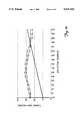
- FIG. 10is a graph of torque as a function of angular deflection for an eccentrically mounted spiral spring (data points shown by squares and triangles), and a concentrically mounted spring (shown by a solid line).
- FIGS. 1 and 2A relatively constant torque, dynamic range-of-motion splint 10 in accordance with the present invention is illustrated generally in FIGS. 1 and 2.
- the illustrated embodiment of splint 10is configured for rehabilitative elbow therapy and includes an upper arm-engaging brace section 12 (i.e., a first brace section for engaging a portion of the patient's body on a first side of the joint), a forearm-engaging brace section 14 (i.e., a second brace section for engaging a portion of the patient's body on the second side of the joint), and drive assembly 16.
- Brace section 12includes an arm assembly 18 formed by rigid arm 20 and extendable arm 22, and an upper arm hook 24 mounted to the extendable arm.
- brace section 14includes an arm assembly 26 formed by rigid arm 28 and extendable arm 30, and forearm hooks 32 and 34.
- Forearm hook 32is mounted to rigid arm 28, while hook 34 is mounted to extendable arm 30.
- Brace sections 12 and 14 and drive assembly 16are interconnected by a dual-axis pivot assembly 36 which is shown in FIGS. 3-6.
- splint 10is mounted to the patient's arm and brace sections 12 and 14 adjusted to align pivot assembly 36 with the rotational axes of the patient's elbow.
- Drive assembly 16provides relatively constant torque in opposition to contractures over the entire range of elbow motion, thereby alleviating the need for torque adjustments as the injury heals and the range of motion increases.
- Pivot assembly 36includes upper arm bracket 37, forearm bracket 39, and an elongated link 38 pivotally connected at one end to the upper arm bracket by pivot pin 40.
- Rigid arm 20 of brace section 12is mounted to upper arm bracket 37 by screws or other fasteners (not shown), while rigid arm 28 of brace section 14 is similarly mounted to bracket 39.
- Pivot pin 40defines a first or primary joint pivot axis about which brace sections 12 and 14 rotate.
- the end of bracket 39 interconnected to pivot assembly 36is bifurcated and includes an elongated gap 42 forming a pair of extensions 44 on opposite sides of the bracket. The ends of extensions 44 are pivotally connected to the sides of link 38 by screws 46.
- Screws 46define a second or lateral joint pivot axis which is perpendicular to the primary splint pivot axis.
- Gap 42is sized to receive link 38 while allowing bracket 39 to pivot with respect to bracket 37 about the lateral joint pivot axis.
- Bracket 37includes an extension 48 which extends beyond pivot pin 40 toward bracket 39 and is configured to engage pivot pin 70 of locking mechanism 90 (described below) to limit the range of rotational motion of brace sections 12 and 14.
- extension 48is located to limit the range of rotational motion between brace sections 12 and 14 to about minus ten degrees.
- the working range of splint 10is between about minus ten degrees at full extension, and about one hundred and fifty degrees at full flexion.
- Drive assembly 16can be described with reference to FIGS. 4-8.
- drive assembly 16includes a drive mechanism 56 mounted to brackets 37 and 39 and enclosed by cover 58.
- Drive mechanism 56includes a spiral spring 60 having a first or inner end 62 and a second or outer end 68.
- Inner end 62is mounted to a slot within the shaft 64 of gear 66.
- Outer end 68is hooked to a pivot pin 70 extending from the end of link 38 opposite pivot pin 40.
- Gear 66is rotatably mounted within cover 58 by a pin 72 which extends through gear shaft 64.
- the end of pin 72 adjacent gear 66is mounted within a recess 74 on the interior surface of the face 59 of cover 58.
- the end of pin 72 adjacent shaft 64is rotatably mounted within a recess or aperture in bracket 37.
- Cover 58is fastened to bracket 37 by screws 63.
- Spring 60is eccentrically mounted with respect to the primary splint pivot axis formed by pin 40. As shown in FIGS. 5-8, the rotational axis of gear pivot pin 72 is offset or spaced from pivot pin 40. In the embodiment shown, when brackets 37 and 39 are linearly aligned, a line (not shown) extending through pins 72 and 40 forms a ninety degree angle with a line (also not shown) extending through pins 40 and 70. In other words, pins 70 and 72 form a right angle with respect to pivot pin 40. The offset between gear pivot pin 72 and pin 40 is one quarter inch (64 mm) in one embodiment. The functional characteristics of eccentrically mounted spring 60 are described below.
- an adjustment worm 78is mounted within recesses in cover 58 for engagement with gear 66 and rotation about an axis perpendicular to pin 72.
- An end 80 of adjustment worm 78extends through the cover side wall 61 and is connected to a crank 82 by pivot pin 84.
- Crank 82is configured for pivotal movement between a retracted position adjacent to cover 58 (shown in solid lines), and an extended position (shown in broken lines).
- the handle 84 of crank of 82can be actuated to rotate adjustment worm 78, thereby rotating gear 66 to wind and unwind spiral spring 60 in order to increase and decrease the amount of torque applied across brace sections 12 and 14 by the spring.
- Gear 66, adjustment worm 78 and crank 82thereby function as a torque adjusting mechanism.
- Locking mechanism 90for releasably locking brace sections 12 and 14 with respect to one another can be described with reference to FIGS. 7 and 8.
- Locking mechanism 90includes a pawl 92 pivotally mounted to pivot pin 70 and a rack 94 formed on the interior surface of cover side wall 61.
- Pawl 92is actuated by a lever 96 which includes a base member 98 and handle 100.
- Base member 98is mounted to pawl 70 and extends outwardly from case 58 between side wall 61 and bracket 39.
- Handle 100extends from base member 98 and is positioned generally adjacent to the exterior of the cover side wall 61.
- Handle 100is actuated to drive pawl 92 between a position disengaged from rack 94, and an over-center position engaged with the rack.
- brace sections 12 and 14can freely rotate with respect to one another.
- pawl 92is biased into engagement with rack 94 by the force of spring 60.
- Locking mechanism 90enables brace sections 12 and 14 to be conveniently and rigidly locked with respect to one another at any desired position within the range of motion of splint 10.
- the teeth forming rack 94are symmetrical or bidirectional. Cover 58 can therefore be used on splints 10 configured for both flexion and extension contractures of joints on both the left and right sides of the patient's body by using different levers 96 that rotate in opposite directions.
- An adjustable range-of-motion stop mechanism 110enables a clinician to control the range of rotational motion between brace sections 12 and 14.
- stop mechanism 110includes threaded holes 112 circumferentially arranged around pivot pin 40 on the end of bracket 37, and a pair of removable pins 114 which can be threadedly engaged with the holes 112. Pins 114 extends from the side of bracket 37 facing bracket 39.
- the range of rotational motion between brace sections 12 and 14is limited by the engagement of pins 114 with the ends of extensions 44 of bracket 39.
- a cliniciancan conveniently reposition one or both pins 114 within holes 112 to adjust the range of motion over which splint 10 can operate as the patient's condition improves.
- Arm assemblies 18 and 26each include a detent-type length adjustment mechanism 120 for adjustably positioning extendable arms 22 and 30 with respect to rigid arms 20 and 28, respectively.
- the length adjusting mechanism 120 on upper arm assembly 18, which can be identical to mechanism 120 on forearm assembly 26,is shown in detail in FIG. 9.
- rigid arm 20is generally "C” shaped in cross section, and functions as track for slidably receiving extendable arm 22.
- a plurality of detent holes 122extend through arm 20 and are aligned along the axis on which extendable arm 22 slides.
- the end of extendable arm 22 engaged with rigid arm 20includes a recess 124 which is sized to receive a biasing member such as leaf spring 126.
- a detent button 128is mounted to spring 126 by a rivet or other fastener 130.
- Button 128is positioned to be linearly aligned with holes 122 as extendable arm 22 slides within rigid arm 20, and sized to engaged the holes.
- Spring 126biases button 128 outwardly into a detent position engaged with holes 122. From the outer surface of rigid arm 20, a clinician can press button 128 into the arm to disengage extendable arm 22, and slide the extendable arm to a position appropriate for the patient. Button 128 can then be released to engage the nearest hole 122, thereby releasably locking the extendable arm 22 with respect to bracket 20.
- Hooks 24, 32 and 34are “C” shaped members, and have open sections (not visible in FIG. 1) enabling the hooks and splint to be mounted to and removed from the patient's arm.
- Forearm hook 34includes a bendable "C” shaped foam covered aluminum member 130 rigidly mounted to extendable arm 30.
- a pad 132 of shape-retaining or “memory” foamis releasably secured to the inner surface of member 130 by hook and loop (e.g., Velcro brand) fasteners (not visible in FIG. 1). Hook 34 securely yet comfortably engages the patient's forearm, while foam pad 132 compensates for variations in the patient's limb structure.
- a strap 134 with hook and loop or other releasable fasteners(not visible in FIG.
- hooks 24 and 32can be structurally and functionally identical to hook 34 described above.
- FIG. 10is a graph of the measured torque of a two inch spiral spring as a function of deflection when the inner end of the spring is spaced from the rotational axis of deflection by one quarter inch. Two sets of measured data for the same spring are shown, with the data points of one set represented by squares and the data points of the other set represented by triangles. For reference, the expected torque characteristics of the spring if it was concentrically mounted on the axis of deflection is shown by a solid line. From FIG. 10 it is evident that the amount of torque generated by the eccentrically mounted spring as a function of deflection is relatively constant with respect to that generated by a concentrically mounted spring.
- Range-of-motion splint 10offers considerable advantages over those shown in the prior art.
- the length adjusting mechanisms and replaceable hook padsenable the brace sections to be conveniently adjusted and fit to patients of varying size.
- the dual axis pivot mechanismallows the splint to accurately follow the natural motion of the patient's body. Relatively constant torque can be applied over the entire working range of the splint without the need for adjustments.
- the amount of torque applied by the splintcan be easily adjusted with the torque adjustment mechanism to accommodate the needs of different patients.
- the range of joint motion over which the splint operatescan be conveniently adjusted with the stop mechanism.
- the use of the lock mechanismenables the patient to comfortably position and remove the splint.
- the splintcan also be efficiently manufactured.
Landscapes
- Health & Medical Sciences (AREA)
- Nursing (AREA)
- Orthopedic Medicine & Surgery (AREA)
- Engineering & Computer Science (AREA)
- Biomedical Technology (AREA)
- Heart & Thoracic Surgery (AREA)
- Vascular Medicine (AREA)
- Life Sciences & Earth Sciences (AREA)
- Animal Behavior & Ethology (AREA)
- General Health & Medical Sciences (AREA)
- Public Health (AREA)
- Veterinary Medicine (AREA)
- Orthopedics, Nursing, And Contraception (AREA)
Abstract
Description
Claims (20)
Priority Applications (7)
| Application Number | Priority Date | Filing Date | Title |
|---|---|---|---|
| US08/205,837US5437619A (en) | 1993-06-30 | 1994-03-04 | Range-of-motion splint with eccentric spring |
| US08/382,993US5520627A (en) | 1993-06-30 | 1995-02-03 | Range-of-motion ankle splint |
| US08/388,482US5520625A (en) | 1993-06-30 | 1995-02-14 | Range-of-motion wrist splint |
| PCT/US1995/002450WO1995023568A1 (en) | 1994-03-04 | 1995-02-28 | Range-of-motion splint with eccentric spring |
| AU19343/95AAU1934395A (en) | 1994-03-04 | 1995-02-28 | Range-of-motion splint with eccentric spring |
| US08/472,339US5571078A (en) | 1993-06-30 | 1995-06-07 | Range-of-motion ankle splint |
| US08/597,667US5759165A (en) | 1993-06-30 | 1996-02-07 | Forearm supination range-of-motion orthosis |
Applications Claiming Priority (2)
| Application Number | Priority Date | Filing Date | Title |
|---|---|---|---|
| US08/085,758US5399154A (en) | 1993-06-30 | 1993-06-30 | Constant torque range-of-motion splint |
| US08/205,837US5437619A (en) | 1993-06-30 | 1994-03-04 | Range-of-motion splint with eccentric spring |
Related Parent Applications (1)
| Application Number | Title | Priority Date | Filing Date |
|---|---|---|---|
| US08/085,758Continuation-In-PartUS5399154A (en) | 1993-06-30 | 1993-06-30 | Constant torque range-of-motion splint |
Related Child Applications (2)
| Application Number | Title | Priority Date | Filing Date |
|---|---|---|---|
| US08/382,993Continuation-In-PartUS5520627A (en) | 1993-06-30 | 1995-02-03 | Range-of-motion ankle splint |
| US08/388,482Continuation-In-PartUS5520625A (en) | 1993-06-30 | 1995-02-14 | Range-of-motion wrist splint |
Publications (1)
| Publication Number | Publication Date |
|---|---|
| US5437619Atrue US5437619A (en) | 1995-08-01 |
Family
ID=22763848
Family Applications (1)
| Application Number | Title | Priority Date | Filing Date |
|---|---|---|---|
| US08/205,837Expired - LifetimeUS5437619A (en) | 1993-06-30 | 1994-03-04 | Range-of-motion splint with eccentric spring |
Country Status (3)
| Country | Link |
|---|---|
| US (1) | US5437619A (en) |
| AU (1) | AU1934395A (en) |
| WO (1) | WO1995023568A1 (en) |
Cited By (110)
| Publication number | Priority date | Publication date | Assignee | Title |
|---|---|---|---|---|
| US5520625A (en)* | 1993-06-30 | 1996-05-28 | Empi, Inc. | Range-of-motion wrist splint |
| WO1998043560A1 (en)* | 1997-03-28 | 1998-10-08 | Trestles Healthcare Inc | Orthotic device for treating contractures due to immobility |
| US5865695A (en)* | 1996-05-17 | 1999-02-02 | Mahala; Robert | Training device for basketball players for developing proper shooting technique |
| US5916189A (en)* | 1997-12-19 | 1999-06-29 | Ge Yokogawa Medical Systems, Limited | Neck fixing apparatus |
| US6001075A (en)* | 1997-12-12 | 1999-12-14 | Ex. P.H. | Dynamic splint |
| DE19904554A1 (en)* | 1999-02-04 | 2000-08-31 | Albrecht Gmbh | Orthesis has distal and proximal rails, linkage, spring arrangement, traction or thrust element, link point and force transmission element |
| US6117097A (en)* | 1998-09-05 | 2000-09-12 | Ruiz; Andres F. | Adjustable tension joint brace apparatus |
| US6129690A (en)* | 1998-07-29 | 2000-10-10 | Empi Corp. | Unidirectional resistance pivot assembly for a splint |
| US6142965A (en)* | 1997-02-25 | 2000-11-07 | Mathewson; Paul R. | Variably adjustable bi-directional derotation bracing system |
| GB2353953A (en)* | 1999-09-11 | 2001-03-14 | Matthew Park | Elbow brace |
| US6245034B1 (en)* | 1998-10-13 | 2001-06-12 | Lenjoy Engineering, Inc. | Adjustable resistance orthopedic splint |
| US6375632B1 (en)* | 1998-05-15 | 2002-04-23 | Albrecht Gmbh | Joint support with a gear wheel adjustment mechanism for the stepless fine adjustment of a pivot range limit |
| US20020072695A1 (en)* | 2000-12-12 | 2002-06-13 | Doty Del Ray | Orthopedic brace having length-adjustable supports |
| US20020183672A1 (en)* | 1999-09-27 | 2002-12-05 | Robert-Jan Enzerink | Orthopaedic brace having a range of motion hinge with an adjustable-length strut |
| US6656144B1 (en)* | 1999-11-22 | 2003-12-02 | Hipbolt Orthopedic Systems | Articulating joint for an orthopedic brace |
| US20030229301A1 (en)* | 2002-02-15 | 2003-12-11 | Joseph Coligado | Articulating joint for an orthopedic brace |
| US6666837B2 (en)* | 1999-08-17 | 2003-12-23 | Medi Bayreuth Weihermuller & Voightman Gmbh & Co. Kg | Orthosis joint |
| US20040153015A1 (en)* | 2003-01-30 | 2004-08-05 | Scott Seligman | Motion controlling hinge for orthopedic brace |
| US20040153016A1 (en)* | 2003-02-04 | 2004-08-05 | Aircast, Inc. | Multi-functional joint brace |
| US20040158184A1 (en)* | 2003-01-16 | 2004-08-12 | Davis Perry H. | Orthopedic splint |
| US20050148915A1 (en)* | 2004-01-07 | 2005-07-07 | Nathanson Jeremy J. | Knee brace hinges having dual axes of rotation |
| US20050148916A1 (en)* | 2004-01-07 | 2005-07-07 | Nathanson Jeremy J. | Knee brace hinges with adaptive motion |
| US20050148918A1 (en)* | 2004-01-06 | 2005-07-07 | Nathanson Jeremy J. | Orthopedic brace suspension system |
| US20050171460A1 (en)* | 2002-02-27 | 2005-08-04 | Karin Behr | Variable arm abduction orthosis |
| US20060009722A1 (en)* | 2004-06-24 | 2006-01-12 | Scott Seligman | Motion controlling hinge for orthopedic brace |
| US20060247565A1 (en)* | 2003-09-29 | 2006-11-02 | David Cormier | Adjustable ergonomic knee brace |
| US20070112394A1 (en)* | 2005-11-16 | 2007-05-17 | N.E.S.S. Neuromuscular Electrical Stimulation Systems Ltd. | Orthosis for a gait modulation system |
| US20080188356A1 (en)* | 2007-02-05 | 2008-08-07 | Bonutti Boris P | Knee orthosis |
| US20080200855A1 (en)* | 2005-05-12 | 2008-08-21 | Linda Pomeroy | Fixator or Splint |
| US20080228118A1 (en)* | 2005-08-18 | 2008-09-18 | Imperial Innovations Limited | Joint Brace |
| CN100428921C (en)* | 2004-02-24 | 2008-10-29 | 鲍尔弗恩德股份有限公司 | Orthotics used to correct the position of joints in the body |
| US7473236B1 (en) | 1997-02-25 | 2009-01-06 | Mathewson Paul R | Variably adjustable bi-directional derotation bracing system |
| US7544174B2 (en) | 2006-09-29 | 2009-06-09 | Djo, Llc | Quiet flexion/extension stop for orthopedic brace and orthopedic brace incorporating a quiet flexion/extension stop |
| US20090177131A1 (en)* | 2005-11-16 | 2009-07-09 | Amit Dar | Gait modulation system and method |
| DE102008011977A1 (en)* | 2008-02-29 | 2009-09-10 | Liebau Orthopädietechnik GmbH | Hip joint orthosis for e.g. supporting musculature of patient after hip joint implantation, has electro stimulation device for generating electro stimulation, where beginning and ending of stimulation is controlled by switch |
| US20090264799A1 (en)* | 2008-03-04 | 2009-10-22 | Bonutti Peter M | Shoulder ROM Orthosis |
| US20090287128A1 (en)* | 2008-05-15 | 2009-11-19 | Arni Thor Ingimundarson | Orthopedic devices utilizing rotary tensioning |
| US20100022929A1 (en)* | 2008-07-24 | 2010-01-28 | Pansiera Timothy T | Snap Lock Assisted Mechanical Joint |
| US20100081978A1 (en)* | 2007-09-14 | 2010-04-01 | Gene C. CHENG | Adjustable immobilizing joint brace |
| US20100174220A1 (en)* | 2009-01-08 | 2010-07-08 | Breg, Inc. | Orthopedic Elbow Brace Having a Length-Adjustable Support Assembly |
| US20110184326A1 (en)* | 2004-12-22 | 2011-07-28 | Arni Thor Ingimundarson | Knee brace and method for securing the same |
| USD658771S1 (en)* | 2010-06-29 | 2012-05-01 | Otto Bock Healthcare Gmbh | Orthosis |
| USD660437S1 (en)* | 2010-03-24 | 2012-05-22 | Otto Bock Healthcare Gmbh | Orthosis |
| US8231560B2 (en) | 2004-12-22 | 2012-07-31 | Ossur Hf | Orthotic device and method for securing the same |
| US20120203156A1 (en)* | 2011-02-07 | 2012-08-09 | Amit Dar | Adjustable orthosis for electrical stimulation of a limb |
| ITVR20120082A1 (en)* | 2012-04-27 | 2013-10-28 | Fgp Srl | JOINT FOR ORTHOPEDIC ORTHOPEDICS APPLICABLE ON ARTS |
| ITVR20120080A1 (en)* | 2012-04-27 | 2013-10-28 | Fgp Srl | ORTHESI FOR THE AID WITH REHABILITATION FUNCTIONS OF THE ARTS |
| USD693930S1 (en) | 2012-07-12 | 2013-11-19 | Ossur Hf | Pair of struts for an orthopedic device |
| US8771211B2 (en) | 2007-03-16 | 2014-07-08 | Bonutti Research, Inc. | Ankle orthosis |
| US8784343B2 (en) | 2005-08-12 | 2014-07-22 | Bonutti Research, Inc. | Range of motion system |
| US8814816B2 (en) | 2004-03-08 | 2014-08-26 | Bonutti Research, Inc. | Range of motion device |
| CN104023678A (en)* | 2011-09-16 | 2014-09-03 | 汤森设计公司 | Knee brace with tool less length adjuster |
| US8852031B2 (en) | 2011-09-20 | 2014-10-07 | Raynard Williams, SR. | Training harness for a basketball defender |
| US8868217B2 (en) | 2011-06-27 | 2014-10-21 | Bioness Neuromodulation Ltd. | Electrode for muscle stimulation |
| US8939925B2 (en) | 2010-02-26 | 2015-01-27 | Ossur Hf | Tightening system for an orthopedic article |
| US8972017B2 (en) | 2005-11-16 | 2015-03-03 | Bioness Neuromodulation Ltd. | Gait modulation system and method |
| US20150119998A1 (en)* | 2012-06-04 | 2015-04-30 | Commissariat a L"energie atomique et aux energies alternatives | Exoskeleton arm having an actuator |
| US20150335455A1 (en)* | 2012-02-07 | 2015-11-26 | S.A.M. Bracing PTY Ltd. | Joint for Rehabilitation Device |
| US9220622B2 (en) | 2004-12-22 | 2015-12-29 | Ossur Hf | Orthopedic device |
| US9248041B2 (en) | 2006-03-20 | 2016-02-02 | Bonutti Research, Inc. | Elbow orthosis |
| DE102014114430A1 (en)* | 2014-08-08 | 2016-02-11 | Gottinger Handelshaus Ohg | orthotic |
| US9314363B2 (en) | 2013-01-24 | 2016-04-19 | Ossur Hf | Orthopedic device for treating complications of the hip |
| US9320638B2 (en) | 2009-02-20 | 2016-04-26 | Cambfix Limited | Fixator |
| US9345606B2 (en) | 1998-06-01 | 2016-05-24 | Bonutti Research, Inc. | Shoulder orthosis |
| US9358146B2 (en) | 2013-01-07 | 2016-06-07 | Ossur Hf | Orthopedic device and method for securing the same |
| US9364365B2 (en) | 2013-01-31 | 2016-06-14 | Ossur Hf | Progressive force strap assembly for use with an orthopedic device |
| US9370440B2 (en) | 2012-01-13 | 2016-06-21 | Ossur Hf | Spinal orthosis |
| US9375341B2 (en) | 2013-01-31 | 2016-06-28 | Ossur Hf | Orthopedic device having detachable components for treatment stages and method for using the same |
| US9414953B2 (en) | 2009-02-26 | 2016-08-16 | Ossur Hf | Orthopedic device for treatment of the back |
| US9439800B2 (en) | 2009-01-14 | 2016-09-13 | Ossur Hf | Orthopedic device, use of orthopedic device and method for producing same |
| US9468578B2 (en) | 2005-10-28 | 2016-10-18 | Bonutti Research Inc. | Range of motion device |
| US9468554B2 (en) | 2013-01-24 | 2016-10-18 | Ossur Iceland Ehf | Orthopedic device for treating complications of the hip |
| US9474334B2 (en) | 2012-11-13 | 2016-10-25 | Ossur Hf | Fastener member for affixation to a structure in an orthopedic device and method for securing the same |
| US9498025B2 (en) | 2013-04-08 | 2016-11-22 | Ossur Hf | Strap attachment system for orthopedic device |
| US20160367392A1 (en)* | 2015-06-22 | 2016-12-22 | Hosso, Inc. | Joint brace with improved range of motion stop |
| US9554935B2 (en) | 2013-01-24 | 2017-01-31 | Ossur Hf | Orthopedic device for treating complications of the hip |
| US9572702B2 (en) | 2010-10-22 | 2017-02-21 | Bonutti Research, Inc. | Shoulder orthosis including flexion/extension device |
| US9572705B2 (en) | 2012-01-13 | 2017-02-21 | Ossur Hf | Spinal orthosis |
| US9597219B2 (en) | 2009-11-04 | 2017-03-21 | Ossur Hf | Thoracic lumbar sacral orthosis |
| US9763808B2 (en) | 2014-05-19 | 2017-09-19 | Ossur Hf | Adjustable prosthetic device |
| US9795500B2 (en) | 2013-01-24 | 2017-10-24 | Ossur Hf | Orthopedic device for treating complications of the hip |
| US9814615B2 (en) | 2004-12-22 | 2017-11-14 | Ossur Hf | Orthopedic device |
| WO2017210212A1 (en)* | 2016-05-31 | 2017-12-07 | United Surgical, Inc. | Flexion and extension range limiting hinge for an orthopedic brace |
| US9844454B2 (en) | 2013-10-31 | 2017-12-19 | Spring Loaded Technology Incorporated | Brace and tension springs for a brace |
| US9867985B2 (en) | 2014-03-24 | 2018-01-16 | Bioness Inc. | Systems and apparatus for gait modulation and methods of use |
| US9872794B2 (en) | 2012-09-19 | 2018-01-23 | Ossur Hf | Panel attachment and circumference adjustment systems for an orthopedic device |
| USD813089S1 (en) | 2016-11-08 | 2018-03-20 | Ossur Iceland Ehf | D-ring |
| US9925082B2 (en) | 2012-03-20 | 2018-03-27 | Ossur Hf | Orthopedic device |
| US9950143B2 (en) | 2012-02-07 | 2018-04-24 | Marie Andrea I. Wilborn | Intravenous splint cover and associated methods |
| KR101872871B1 (en)* | 2017-07-13 | 2018-07-02 | 정한영 | Apparatus For Supporting Jointing Movement |
| US10052221B2 (en) | 2015-01-06 | 2018-08-21 | Ossur Iceland Ehf | Orthopedic device for treating osteoarthritis of the knee |
| USD835289S1 (en) | 2016-11-08 | 2018-12-04 | Ossur Iceland Ehf | Orthopedic device |
| US10159592B2 (en) | 2015-02-27 | 2018-12-25 | Ossur Iceland Ehf | Spinal orthosis, kit and method for using the same |
| US10182935B2 (en) | 2014-10-01 | 2019-01-22 | Ossur Hf | Support for articles and methods for using the same |
| US10188539B2 (en) | 2015-10-05 | 2019-01-29 | SpringLoaded Technology Incorporated | Stabilizing system for a knee brace |
| US10512305B2 (en) | 2014-07-11 | 2019-12-24 | Ossur Hf | Tightening system with a tension control mechanism |
| US10561520B2 (en) | 2015-02-27 | 2020-02-18 | Ossur Iceland Ehf | Spinal orthosis, kit and method for using the same |
| US10617549B2 (en) | 2016-04-04 | 2020-04-14 | Ossur Iceland Ehf | Orthopedic device |
| USD882803S1 (en) | 2018-10-08 | 2020-04-28 | Ossur Iceland Ehf | Orthopedic shell |
| USD888258S1 (en) | 2018-10-08 | 2020-06-23 | Ossur Iceland Ehf | Connector assembly |
| USD908458S1 (en) | 2018-10-08 | 2021-01-26 | Ossur Iceland Ehf | Hinge cover |
| US11000439B2 (en) | 2017-09-28 | 2021-05-11 | Ossur Iceland Ehf | Body interface |
| US11077300B2 (en) | 2016-01-11 | 2021-08-03 | Bioness Inc. | Systems and apparatus for gait modulation and methods of use |
| US11234850B2 (en) | 2016-06-06 | 2022-02-01 | Ossur Iceland Ehf | Orthopedic device, strap system and method for securing the same |
| US11241353B2 (en) | 2017-11-09 | 2022-02-08 | The Curators Of The University Of Missouri | Knee flexion device and associated method of use |
| US11246734B2 (en) | 2017-09-07 | 2022-02-15 | Ossur Iceland Ehf | Thoracic lumbar sacral orthosis attachment |
| US20220409416A1 (en)* | 2020-02-28 | 2022-12-29 | Ottobock Se & Co. Kgaa | Orthosis joint |
| US11547589B2 (en) | 2017-10-06 | 2023-01-10 | Ossur Iceland Ehf | Orthopedic device for unloading a knee |
| US11850175B2 (en) | 2016-06-06 | 2023-12-26 | Ossur Iceland Ehf | Orthopedic device, strap system and method for securing the same |
| US11872150B2 (en) | 2020-12-28 | 2024-01-16 | Ossur Iceland Ehf | Sleeve and method for use with orthopedic device |
Families Citing this family (7)
| Publication number | Priority date | Publication date | Assignee | Title |
|---|---|---|---|---|
| DE19645076A1 (en)* | 1996-10-31 | 1998-05-14 | Albrecht Gmbh | Device for reducing extension or flexion deficits of a distal limb compared to a proximal limb |
| US6142964A (en)* | 1997-03-27 | 2000-11-07 | Bodyworks Properties Limited | Multi-planar brace |
| DE19801951A1 (en)* | 1998-01-20 | 1999-07-29 | Andreas Hasler | Arm splint of upper and forearm parts |
| US6039707A (en)* | 1999-02-16 | 2000-03-21 | Crawford; Michael K. | Pelvic support and walking assistance device |
| DE19935058B4 (en) | 1999-07-28 | 2007-06-28 | Hassler, Andreas | Articular splint system with independently operable fixation |
| KR100817531B1 (en) | 2006-03-28 | 2008-03-27 | 김양수 | Universal elbow hinge brace |
| GB201018749D0 (en)* | 2010-11-08 | 2010-12-22 | C Pro Direct Ltd | Ankle foot orthopaedic devices |
Citations (50)
| Publication number | Priority date | Publication date | Assignee | Title |
|---|---|---|---|---|
| US42799A (en)* | 1864-05-17 | Improvement in artificial legs | ||
| US1847823A (en)* | 1929-08-23 | 1932-03-01 | Frank A Dresser | Leg brace |
| US1851241A (en)* | 1931-01-23 | 1932-03-29 | Frank A Dresser | Leg brace |
| US2395768A (en)* | 1943-07-01 | 1946-02-26 | Svoboda Antonin | Spring device |
| US2413634A (en)* | 1944-05-18 | 1946-12-31 | Kolarik John | Caliper brace |
| US2646793A (en)* | 1950-04-13 | 1953-07-28 | Swiech Edward | Self-locking and unlocking pivot joint for leg braces |
| US2675578A (en)* | 1951-07-02 | 1954-04-20 | Atwood Vacuum Machine Co | Automobile door check and hold-open device |
| US2797431A (en)* | 1953-04-15 | 1957-07-02 | Gen Motors Corp | Door check and holdopen |
| US2934785A (en)* | 1957-07-29 | 1960-05-03 | Lawrence H Heuer | Counterbalance spring |
| US3086521A (en)* | 1961-02-06 | 1963-04-23 | Univ California | Lower leg brace |
| US4180870A (en)* | 1975-04-15 | 1980-01-01 | Fa Wilh. Jul. Teufel | Universal-orthese |
| US4252111A (en)* | 1977-05-20 | 1981-02-24 | Nasa | Locking mechanism for orthopedic braces |
| US4397308A (en)* | 1981-07-23 | 1983-08-09 | Therapeutic Appliances, Inc. | Adjustable splint |
| US4433679A (en)* | 1981-05-04 | 1984-02-28 | Mauldin Donald M | Knee and elbow brace |
| US4456002A (en)* | 1982-09-27 | 1984-06-26 | L M B Hand Rehab Products | Spring metacarpophalangeal flexion splint (knuckle splint) |
| US4485808A (en)* | 1982-04-12 | 1984-12-04 | Dynasplint Systems, Inc. | Adjustable splint |
| US4489718A (en)* | 1983-03-08 | 1984-12-25 | Medical Designs, Inc. | Knee brace hinge |
| US4493316A (en)* | 1983-03-10 | 1985-01-15 | Donjoy, Inc. | Articulating knee stabilizer |
| US4508111A (en)* | 1981-07-23 | 1985-04-02 | Dynasplint Systems, Inc. | Adjustable splint |
| US4520804A (en)* | 1981-08-04 | 1985-06-04 | Digeorge Michael A | Double-locking ratchet for orthopedic brace |
| US4538600A (en)* | 1983-10-27 | 1985-09-03 | Dynasplint Systems, Inc. | Adjustable splint |
| US4565190A (en)* | 1984-07-13 | 1986-01-21 | Northwestern University | Knee orthosis with swivel-action supracondular cuff |
| US4602620A (en)* | 1985-09-16 | 1986-07-29 | Marx Ralph H | Dynamic outrigger extension for dorsal wrist splints |
| US4624246A (en)* | 1985-11-01 | 1986-11-25 | Krikor Ajemian | Knee-supporting brace |
| US4633867A (en)* | 1984-06-27 | 1987-01-06 | James H. Kausek | Knee brace for control of ligament instability |
| US4643177A (en)* | 1984-06-13 | 1987-02-17 | University Of Florida | Dynamic traction wrist cast brace |
| US4657000A (en)* | 1981-07-23 | 1987-04-14 | Dynasplints Systems, Inc. | Adjustable splint and securing means therefor |
| US4719906A (en)* | 1987-05-07 | 1988-01-19 | Deprospero Rose | Universal articulated splint |
| US4726361A (en)* | 1986-01-10 | 1988-02-23 | Farley Michael D | Method and apparatus for correction of defects in an equine leg |
| US4729254A (en)* | 1985-03-14 | 1988-03-08 | Isumi Corporation Industries, Inc. | Steering system |
| US4738252A (en)* | 1987-09-18 | 1988-04-19 | Friddle's Orthopedic Appliances, Inc. | Mechanical joint construction |
| SU1426580A1 (en)* | 1987-02-04 | 1988-09-30 | Научно-исследовательский институт травматологии и ортопедии | Arrangement for mechanotherapy of fingers of the hand |
| US4790301A (en)* | 1987-10-23 | 1988-12-13 | Krister Silfverskiold | Device for and method of dynamic splinting |
| US4817588A (en)* | 1987-07-01 | 1989-04-04 | Medical Technology, Inc. | Motion restraining knee brace |
| US4844057A (en)* | 1987-11-16 | 1989-07-04 | David Hoy | Knee orthotic hinge joint |
| US4862878A (en)* | 1988-01-07 | 1989-09-05 | Richards Medical Company | Orthopedic prosthesis to aid and support the shoulder muscles in movement of the human arm |
| US4865024A (en)* | 1988-10-21 | 1989-09-12 | Hensley Dvid E | Extension deceleration orthosis |
| US4873967A (en)* | 1987-04-27 | 1989-10-17 | Sutherland Jeffrey L | Knee orthosis |
| US4947835A (en)* | 1989-04-05 | 1990-08-14 | Dynasplint Systems, Inc. | Adjustable splint assembly |
| US5000169A (en)* | 1990-01-16 | 1991-03-19 | Clinitex Corporation | Adjustable flexion-extension hinge for hinged limb immobilizer |
| US5002044A (en)* | 1989-10-10 | 1991-03-26 | Carter Peter R | Derotation wrist brace |
| US5002045A (en)* | 1988-03-16 | 1991-03-26 | Spademan Richard George | Cuff device |
| US5025782A (en)* | 1990-02-12 | 1991-06-25 | Ambulatory Traction Inc. | Adjustable rack and pinion knee brace |
| US5036837A (en)* | 1990-02-09 | 1991-08-06 | Bio-Tec, Inc. | Dynamic extension splint |
| US5052379A (en)* | 1989-04-27 | 1991-10-01 | Soma Dynamics Corporation | Combination brace and wearable exercise apparatus for body joints |
| US5060640A (en)* | 1990-03-14 | 1991-10-29 | Becker Orthopedic Appliance Company | Knee brace |
| US5063917A (en)* | 1989-08-14 | 1991-11-12 | Protectair Limited | Limb brace or immobilizer |
| US5167612A (en)* | 1990-07-30 | 1992-12-01 | Bonutti Peter M | Adjustable orthosis |
| US5242379A (en)* | 1990-07-02 | 1993-09-07 | Exoflex, Inc. | Ankle brace with floating pivot hinge |
| US5352190A (en)* | 1990-03-16 | 1994-10-04 | Q-Motus, Inc. | Knee brace |
- 1994
- 1994-03-04USUS08/205,837patent/US5437619A/ennot_activeExpired - Lifetime
- 1995
- 1995-02-28WOPCT/US1995/002450patent/WO1995023568A1/enactiveApplication Filing
- 1995-02-28AUAU19343/95Apatent/AU1934395A/ennot_activeAbandoned
Patent Citations (50)
| Publication number | Priority date | Publication date | Assignee | Title |
|---|---|---|---|---|
| US42799A (en)* | 1864-05-17 | Improvement in artificial legs | ||
| US1847823A (en)* | 1929-08-23 | 1932-03-01 | Frank A Dresser | Leg brace |
| US1851241A (en)* | 1931-01-23 | 1932-03-29 | Frank A Dresser | Leg brace |
| US2395768A (en)* | 1943-07-01 | 1946-02-26 | Svoboda Antonin | Spring device |
| US2413634A (en)* | 1944-05-18 | 1946-12-31 | Kolarik John | Caliper brace |
| US2646793A (en)* | 1950-04-13 | 1953-07-28 | Swiech Edward | Self-locking and unlocking pivot joint for leg braces |
| US2675578A (en)* | 1951-07-02 | 1954-04-20 | Atwood Vacuum Machine Co | Automobile door check and hold-open device |
| US2797431A (en)* | 1953-04-15 | 1957-07-02 | Gen Motors Corp | Door check and holdopen |
| US2934785A (en)* | 1957-07-29 | 1960-05-03 | Lawrence H Heuer | Counterbalance spring |
| US3086521A (en)* | 1961-02-06 | 1963-04-23 | Univ California | Lower leg brace |
| US4180870A (en)* | 1975-04-15 | 1980-01-01 | Fa Wilh. Jul. Teufel | Universal-orthese |
| US4252111A (en)* | 1977-05-20 | 1981-02-24 | Nasa | Locking mechanism for orthopedic braces |
| US4433679A (en)* | 1981-05-04 | 1984-02-28 | Mauldin Donald M | Knee and elbow brace |
| US4397308A (en)* | 1981-07-23 | 1983-08-09 | Therapeutic Appliances, Inc. | Adjustable splint |
| US4508111A (en)* | 1981-07-23 | 1985-04-02 | Dynasplint Systems, Inc. | Adjustable splint |
| US4657000A (en)* | 1981-07-23 | 1987-04-14 | Dynasplints Systems, Inc. | Adjustable splint and securing means therefor |
| US4520804A (en)* | 1981-08-04 | 1985-06-04 | Digeorge Michael A | Double-locking ratchet for orthopedic brace |
| US4485808A (en)* | 1982-04-12 | 1984-12-04 | Dynasplint Systems, Inc. | Adjustable splint |
| US4456002A (en)* | 1982-09-27 | 1984-06-26 | L M B Hand Rehab Products | Spring metacarpophalangeal flexion splint (knuckle splint) |
| US4489718A (en)* | 1983-03-08 | 1984-12-25 | Medical Designs, Inc. | Knee brace hinge |
| US4493316A (en)* | 1983-03-10 | 1985-01-15 | Donjoy, Inc. | Articulating knee stabilizer |
| US4538600A (en)* | 1983-10-27 | 1985-09-03 | Dynasplint Systems, Inc. | Adjustable splint |
| US4643177A (en)* | 1984-06-13 | 1987-02-17 | University Of Florida | Dynamic traction wrist cast brace |
| US4633867A (en)* | 1984-06-27 | 1987-01-06 | James H. Kausek | Knee brace for control of ligament instability |
| US4565190A (en)* | 1984-07-13 | 1986-01-21 | Northwestern University | Knee orthosis with swivel-action supracondular cuff |
| US4729254A (en)* | 1985-03-14 | 1988-03-08 | Isumi Corporation Industries, Inc. | Steering system |
| US4602620A (en)* | 1985-09-16 | 1986-07-29 | Marx Ralph H | Dynamic outrigger extension for dorsal wrist splints |
| US4624246A (en)* | 1985-11-01 | 1986-11-25 | Krikor Ajemian | Knee-supporting brace |
| US4726361A (en)* | 1986-01-10 | 1988-02-23 | Farley Michael D | Method and apparatus for correction of defects in an equine leg |
| SU1426580A1 (en)* | 1987-02-04 | 1988-09-30 | Научно-исследовательский институт травматологии и ортопедии | Arrangement for mechanotherapy of fingers of the hand |
| US4873967A (en)* | 1987-04-27 | 1989-10-17 | Sutherland Jeffrey L | Knee orthosis |
| US4719906A (en)* | 1987-05-07 | 1988-01-19 | Deprospero Rose | Universal articulated splint |
| US4817588A (en)* | 1987-07-01 | 1989-04-04 | Medical Technology, Inc. | Motion restraining knee brace |
| US4738252A (en)* | 1987-09-18 | 1988-04-19 | Friddle's Orthopedic Appliances, Inc. | Mechanical joint construction |
| US4790301A (en)* | 1987-10-23 | 1988-12-13 | Krister Silfverskiold | Device for and method of dynamic splinting |
| US4844057A (en)* | 1987-11-16 | 1989-07-04 | David Hoy | Knee orthotic hinge joint |
| US4862878A (en)* | 1988-01-07 | 1989-09-05 | Richards Medical Company | Orthopedic prosthesis to aid and support the shoulder muscles in movement of the human arm |
| US5002045A (en)* | 1988-03-16 | 1991-03-26 | Spademan Richard George | Cuff device |
| US4865024A (en)* | 1988-10-21 | 1989-09-12 | Hensley Dvid E | Extension deceleration orthosis |
| US4947835A (en)* | 1989-04-05 | 1990-08-14 | Dynasplint Systems, Inc. | Adjustable splint assembly |
| US5052379A (en)* | 1989-04-27 | 1991-10-01 | Soma Dynamics Corporation | Combination brace and wearable exercise apparatus for body joints |
| US5063917A (en)* | 1989-08-14 | 1991-11-12 | Protectair Limited | Limb brace or immobilizer |
| US5002044A (en)* | 1989-10-10 | 1991-03-26 | Carter Peter R | Derotation wrist brace |
| US5000169A (en)* | 1990-01-16 | 1991-03-19 | Clinitex Corporation | Adjustable flexion-extension hinge for hinged limb immobilizer |
| US5036837A (en)* | 1990-02-09 | 1991-08-06 | Bio-Tec, Inc. | Dynamic extension splint |
| US5025782A (en)* | 1990-02-12 | 1991-06-25 | Ambulatory Traction Inc. | Adjustable rack and pinion knee brace |
| US5060640A (en)* | 1990-03-14 | 1991-10-29 | Becker Orthopedic Appliance Company | Knee brace |
| US5352190A (en)* | 1990-03-16 | 1994-10-04 | Q-Motus, Inc. | Knee brace |
| US5242379A (en)* | 1990-07-02 | 1993-09-07 | Exoflex, Inc. | Ankle brace with floating pivot hinge |
| US5167612A (en)* | 1990-07-30 | 1992-12-01 | Bonutti Peter M | Adjustable orthosis |
Cited By (230)
| Publication number | Priority date | Publication date | Assignee | Title |
|---|---|---|---|---|
| US5520625A (en)* | 1993-06-30 | 1996-05-28 | Empi, Inc. | Range-of-motion wrist splint |
| US5865695A (en)* | 1996-05-17 | 1999-02-02 | Mahala; Robert | Training device for basketball players for developing proper shooting technique |
| US6142965A (en)* | 1997-02-25 | 2000-11-07 | Mathewson; Paul R. | Variably adjustable bi-directional derotation bracing system |
| US7473236B1 (en) | 1997-02-25 | 2009-01-06 | Mathewson Paul R | Variably adjustable bi-directional derotation bracing system |
| WO1998043560A1 (en)* | 1997-03-28 | 1998-10-08 | Trestles Healthcare Inc | Orthotic device for treating contractures due to immobility |
| US6456884B1 (en) | 1997-03-28 | 2002-09-24 | Trestles Healthcare, Inc. | Orthotic/electrotherapy for treating contractures due to immobility |
| US6064912A (en)* | 1997-03-28 | 2000-05-16 | Kenney; John P. | Orthotic/electrotherapy for treating contractures due to immobility |
| AU740869B2 (en)* | 1997-03-28 | 2001-11-15 | John P. Kenney | Orthotic device for treating contractures due to immobility |
| US6001075A (en)* | 1997-12-12 | 1999-12-14 | Ex. P.H. | Dynamic splint |
| US5916189A (en)* | 1997-12-19 | 1999-06-29 | Ge Yokogawa Medical Systems, Limited | Neck fixing apparatus |
| US6375632B1 (en)* | 1998-05-15 | 2002-04-23 | Albrecht Gmbh | Joint support with a gear wheel adjustment mechanism for the stepless fine adjustment of a pivot range limit |
| US9345606B2 (en) | 1998-06-01 | 2016-05-24 | Bonutti Research, Inc. | Shoulder orthosis |
| US6129690A (en)* | 1998-07-29 | 2000-10-10 | Empi Corp. | Unidirectional resistance pivot assembly for a splint |
| US6117097A (en)* | 1998-09-05 | 2000-09-12 | Ruiz; Andres F. | Adjustable tension joint brace apparatus |
| US6245034B1 (en)* | 1998-10-13 | 2001-06-12 | Lenjoy Engineering, Inc. | Adjustable resistance orthopedic splint |
| DE19904554B4 (en)* | 1999-02-04 | 2007-04-26 | Albrecht Gmbh | Two-sided orthosis to reduce stretch and / or flexor deficits |
| DE19904554A1 (en)* | 1999-02-04 | 2000-08-31 | Albrecht Gmbh | Orthesis has distal and proximal rails, linkage, spring arrangement, traction or thrust element, link point and force transmission element |
| US6666837B2 (en)* | 1999-08-17 | 2003-12-23 | Medi Bayreuth Weihermuller & Voightman Gmbh & Co. Kg | Orthosis joint |
| GB2353953A (en)* | 1999-09-11 | 2001-03-14 | Matthew Park | Elbow brace |
| US20080306421A1 (en)* | 1999-09-27 | 2008-12-11 | Robert-Jan Enzerink | Orthopaedic brace having a range of motion hinge with an adjustable-length strut |
| US7097627B2 (en) | 1999-09-27 | 2006-08-29 | Dj Orthopedics, Llc | Orthopaedic brace having a range of motion hinge with an adjustable-length strut |
| US20060293624A1 (en)* | 1999-09-27 | 2006-12-28 | Robert-Jan Enzerink | Orthopaedic brace having a range of motion hinge with an adjustable-length strut |
| US7918809B2 (en)* | 1999-09-27 | 2011-04-05 | Djo, Llc | Orthopaedic brace having a range of motion hinge with an adjustable-length strut |
| US7384406B2 (en)* | 1999-09-27 | 2008-06-10 | Djo, Llc | Orthopaedic brace having a range of motion hinge with an adjustable-length strut |
| US20020183672A1 (en)* | 1999-09-27 | 2002-12-05 | Robert-Jan Enzerink | Orthopaedic brace having a range of motion hinge with an adjustable-length strut |
| US20050059916A2 (en)* | 1999-09-27 | 2005-03-17 | Robert-Jan Enzerink | Orthopaedic brace having a range of motion hinge with an adjustable-length strut |
| US6656144B1 (en)* | 1999-11-22 | 2003-12-02 | Hipbolt Orthopedic Systems | Articulating joint for an orthopedic brace |
| US20020072695A1 (en)* | 2000-12-12 | 2002-06-13 | Doty Del Ray | Orthopedic brace having length-adjustable supports |
| WO2002047588A3 (en)* | 2000-12-12 | 2003-04-24 | Dj Orthopedics Llc | Orthopedic brace having length-adjustable supports |
| US20050107730A1 (en)* | 2000-12-12 | 2005-05-19 | Doty Del R. | Orthopedic brace having length-adjustable supports |
| US6821261B2 (en) | 2000-12-12 | 2004-11-23 | Dj Orthopedics, Llc | Orthopedic brace having length-adjustable supports |
| AU2002232583B2 (en)* | 2000-12-12 | 2006-02-02 | Dj Orthopedics, Llc | Orthopedic brace having length-adjustable supports |
| US20060241540A1 (en)* | 2000-12-12 | 2006-10-26 | Doty Del R | Orthopedic brace having length-adjustable supports |
| US7128723B2 (en) | 2000-12-12 | 2006-10-31 | Dj Orthopedics, Llc | Orthopedic brace having length-adjustable supports |
| US8517965B2 (en)* | 2000-12-12 | 2013-08-27 | Djo, Llc | Orthopedic brace having length-adjustable supports |
| US7699798B2 (en) | 2002-02-15 | 2010-04-20 | Hipbolt I.P., Inc. | Articulating joint for an orthopedic brace |
| US20030229301A1 (en)* | 2002-02-15 | 2003-12-11 | Joseph Coligado | Articulating joint for an orthopedic brace |
| US20050171460A1 (en)* | 2002-02-27 | 2005-08-04 | Karin Behr | Variable arm abduction orthosis |
| US6936020B2 (en) | 2003-01-16 | 2005-08-30 | Perry H. Davis | Orthopedic splint |
| US20040158184A1 (en)* | 2003-01-16 | 2004-08-12 | Davis Perry H. | Orthopedic splint |
| US7192407B2 (en) | 2003-01-30 | 2007-03-20 | Djo, Llc | Motion controlling hinge for orthopedic brace |
| US20090198161A1 (en)* | 2003-01-30 | 2009-08-06 | Djo, Llc | Motion controlling hinge for orthopedic brace |
| US7534217B2 (en) | 2003-01-30 | 2009-05-19 | Djo, Llc | Motion controlling hinge for orthopedic brace |
| US20040153015A1 (en)* | 2003-01-30 | 2004-08-05 | Scott Seligman | Motion controlling hinge for orthopedic brace |
| US20070135745A1 (en)* | 2003-01-30 | 2007-06-14 | Scott Seligman | Motion controlling hinge for orthopedic brace |
| US7846115B2 (en) | 2003-01-30 | 2010-12-07 | Djo, Llc | Motion controlling hinge for orthopedic brace |
| EP1599157A4 (en)* | 2003-02-04 | 2006-04-12 | Aircast Llc | Multi-functional joint brace |
| US7156818B2 (en) | 2003-02-04 | 2007-01-02 | Djo, Llc | Multi-functional joint brace |
| US20040153016A1 (en)* | 2003-02-04 | 2004-08-05 | Aircast, Inc. | Multi-functional joint brace |
| US7517329B2 (en) | 2003-02-04 | 2009-04-14 | Djo, Llc | Multi-functional joint brace |
| US7833181B2 (en) | 2003-09-29 | 2010-11-16 | Ossur Americas, Inc. | Adjustable ergonomic brace |
| US20090227926A1 (en)* | 2003-09-29 | 2009-09-10 | David Cormier | Adjustable ergonomic brace |
| US20060247565A1 (en)* | 2003-09-29 | 2006-11-02 | David Cormier | Adjustable ergonomic knee brace |
| US7534220B2 (en)* | 2003-09-29 | 2009-05-19 | Ossur Hf | Adjustable ergonomic brace |
| US20050148918A1 (en)* | 2004-01-06 | 2005-07-07 | Nathanson Jeremy J. | Orthopedic brace suspension system |
| US7967765B2 (en) | 2004-01-06 | 2011-06-28 | Djo, Llc | Orthopedic brace suspension system |
| US20050148915A1 (en)* | 2004-01-07 | 2005-07-07 | Nathanson Jeremy J. | Knee brace hinges having dual axes of rotation |
| US8043243B2 (en) | 2004-01-07 | 2011-10-25 | Djo, Llc | Knee brace hinges having dual axes of rotation |
| US7615025B2 (en) | 2004-01-07 | 2009-11-10 | Djo, Llc | Knee brace hinges with adaptive motion |
| US20050148916A1 (en)* | 2004-01-07 | 2005-07-07 | Nathanson Jeremy J. | Knee brace hinges with adaptive motion |
| CN100428921C (en)* | 2004-02-24 | 2008-10-29 | 鲍尔弗恩德股份有限公司 | Orthotics used to correct the position of joints in the body |
| US8814816B2 (en) | 2004-03-08 | 2014-08-26 | Bonutti Research, Inc. | Range of motion device |
| US9314392B2 (en) | 2004-03-08 | 2016-04-19 | Bonutti Research, Inc. | Range of motion device |
| US9445966B2 (en) | 2004-03-08 | 2016-09-20 | Bonutti Research, Inc. | Range of motion device |
| US20060009722A1 (en)* | 2004-06-24 | 2006-01-12 | Scott Seligman | Motion controlling hinge for orthopedic brace |
| US7811242B2 (en) | 2004-06-24 | 2010-10-12 | Djo, Llc | Motion controlling hinge for orthopedic brace |
| US8016781B2 (en) | 2004-12-22 | 2011-09-13 | Ossur Hf | Knee brace and method for securing the same |
| US8864692B2 (en) | 2004-12-22 | 2014-10-21 | Ossur Hf | Knee brace and method for securing the same |
| US9814615B2 (en) | 2004-12-22 | 2017-11-14 | Ossur Hf | Orthopedic device |
| US11529250B2 (en) | 2004-12-22 | 2022-12-20 | Ossur Hf | Orthopedic device |
| US11129740B2 (en) | 2004-12-22 | 2021-09-28 | Ossur Hf | Orthopedic device |
| US9265645B2 (en) | 2004-12-22 | 2016-02-23 | Ossur Hf | Orthotic device and method for securing the same |
| US8231560B2 (en) | 2004-12-22 | 2012-07-31 | Ossur Hf | Orthotic device and method for securing the same |
| US20110184326A1 (en)* | 2004-12-22 | 2011-07-28 | Arni Thor Ingimundarson | Knee brace and method for securing the same |
| US9220622B2 (en) | 2004-12-22 | 2015-12-29 | Ossur Hf | Orthopedic device |
| US20080200855A1 (en)* | 2005-05-12 | 2008-08-21 | Linda Pomeroy | Fixator or Splint |
| US7841998B2 (en)* | 2005-05-12 | 2010-11-30 | Linda Pomeroy | Fixator or splint |
| US9320669B2 (en) | 2005-08-12 | 2016-04-26 | Bonutti Research, Inc. | Range of motion system |
| US8784343B2 (en) | 2005-08-12 | 2014-07-22 | Bonutti Research, Inc. | Range of motion system |
| US20080228118A1 (en)* | 2005-08-18 | 2008-09-18 | Imperial Innovations Limited | Joint Brace |
| US9468578B2 (en) | 2005-10-28 | 2016-10-18 | Bonutti Research Inc. | Range of motion device |
| US10456314B2 (en) | 2005-10-28 | 2019-10-29 | Bonutti Research, Inc. | Range of motion device |
| US20090177131A1 (en)* | 2005-11-16 | 2009-07-09 | Amit Dar | Gait modulation system and method |
| US8972017B2 (en) | 2005-11-16 | 2015-03-03 | Bioness Neuromodulation Ltd. | Gait modulation system and method |
| US8209036B2 (en) | 2005-11-16 | 2012-06-26 | Bioness Neuromodulation Ltd. | Orthosis for a gait modulation system |
| US20070112394A1 (en)* | 2005-11-16 | 2007-05-17 | N.E.S.S. Neuromuscular Electrical Stimulation Systems Ltd. | Orthosis for a gait modulation system |
| US8209022B2 (en) | 2005-11-16 | 2012-06-26 | Bioness Neuromodulation Ltd. | Gait modulation system and method |
| US10076656B2 (en) | 2005-11-16 | 2018-09-18 | Bioness Neuromodulation Ltd. | Gait modulation system and method |
| US10080885B2 (en) | 2005-11-16 | 2018-09-25 | Bioness Neuromodulation Ltd. | Orthosis for a gait modulation system |
| US7899556B2 (en) | 2005-11-16 | 2011-03-01 | Bioness Neuromodulation Ltd. | Orthosis for a gait modulation system |
| US8694110B2 (en) | 2005-11-16 | 2014-04-08 | Bioness Neuromodulation Ltd. | Orthosis for gait modulation |
| US20110152968A1 (en)* | 2005-11-16 | 2011-06-23 | Bioness Neuromodulation Ltd. | Orthosis for a gait modulation system |
| US11058867B2 (en) | 2005-11-16 | 2021-07-13 | Bioness Neuromodulation Ltd. | Orthosis for a gait modulation system |
| US11266520B2 (en) | 2006-03-17 | 2022-03-08 | Bonutti Research, Inc. | Ankle orthosis |
| US10159590B2 (en) | 2006-03-17 | 2018-12-25 | Bonutti Research, Inc. | Toe orthosis |
| US10159591B2 (en) | 2006-03-20 | 2018-12-25 | Bonutti Research, Inc. | Elbow orthosis |
| US11123212B2 (en) | 2006-03-20 | 2021-09-21 | Bonutti Research Inc. | Elbow orthosis |
| US9248041B2 (en) | 2006-03-20 | 2016-02-02 | Bonutti Research, Inc. | Elbow orthosis |
| US7544174B2 (en) | 2006-09-29 | 2009-06-09 | Djo, Llc | Quiet flexion/extension stop for orthopedic brace and orthopedic brace incorporating a quiet flexion/extension stop |
| US9980871B2 (en) | 2007-02-05 | 2018-05-29 | Bonutti Research, Inc. | Knee orthosis |
| US20080188356A1 (en)* | 2007-02-05 | 2008-08-07 | Bonutti Boris P | Knee orthosis |
| US8920346B2 (en) | 2007-02-05 | 2014-12-30 | Bonutti Research Inc. | Knee orthosis |
| US8771211B2 (en) | 2007-03-16 | 2014-07-08 | Bonutti Research, Inc. | Ankle orthosis |
| US8979780B2 (en) | 2007-09-14 | 2015-03-17 | Gene C. CHENG | Adjustable immobilizing joint brace |
| US20100081978A1 (en)* | 2007-09-14 | 2010-04-01 | Gene C. CHENG | Adjustable immobilizing joint brace |
| DE102008011977A1 (en)* | 2008-02-29 | 2009-09-10 | Liebau Orthopädietechnik GmbH | Hip joint orthosis for e.g. supporting musculature of patient after hip joint implantation, has electro stimulation device for generating electro stimulation, where beginning and ending of stimulation is controlled by switch |
| US20090264799A1 (en)* | 2008-03-04 | 2009-10-22 | Bonutti Peter M | Shoulder ROM Orthosis |
| US8905950B2 (en) | 2008-03-04 | 2014-12-09 | Bonutti Research, Inc. | Shoulder ROM orthosis |
| US10492940B2 (en) | 2008-05-15 | 2019-12-03 | Ossur Hf | Orthopedic devices utilizing rotary tensioning |
| US20090287128A1 (en)* | 2008-05-15 | 2009-11-19 | Arni Thor Ingimundarson | Orthopedic devices utilizing rotary tensioning |
| US8858482B2 (en) | 2008-05-15 | 2014-10-14 | Ossur Hf | Orthopedic devices utilizing rotary tensioning |
| US20100022929A1 (en)* | 2008-07-24 | 2010-01-28 | Pansiera Timothy T | Snap Lock Assisted Mechanical Joint |
| US8123711B2 (en)* | 2008-07-24 | 2012-02-28 | Fillauer Companies, Inc. | Snap lock assisted mechanical joint |
| US7988653B2 (en) | 2009-01-08 | 2011-08-02 | Breg, Inc. | Orthopedic elbow brace having a length-adjustable support assembly |
| US20100174220A1 (en)* | 2009-01-08 | 2010-07-08 | Breg, Inc. | Orthopedic Elbow Brace Having a Length-Adjustable Support Assembly |
| US9439800B2 (en) | 2009-01-14 | 2016-09-13 | Ossur Hf | Orthopedic device, use of orthopedic device and method for producing same |
| US9320638B2 (en) | 2009-02-20 | 2016-04-26 | Cambfix Limited | Fixator |
| US10828186B2 (en) | 2009-02-26 | 2020-11-10 | Ossur Hf | Orthopedic device for treatment of the back |
| US9414953B2 (en) | 2009-02-26 | 2016-08-16 | Ossur Hf | Orthopedic device for treatment of the back |
| US12127965B2 (en) | 2009-02-26 | 2024-10-29 | Ossur Hf | Orthopedic device for treatment of the back |
| US9597219B2 (en) | 2009-11-04 | 2017-03-21 | Ossur Hf | Thoracic lumbar sacral orthosis |
| US10617552B2 (en) | 2009-11-04 | 2020-04-14 | Ossur Hf | Thoracic lumbar sacral orthosis |
| US10264835B2 (en) | 2010-02-26 | 2019-04-23 | Ossur Hf | Tightening system for an orthopedic article |
| US8939925B2 (en) | 2010-02-26 | 2015-01-27 | Ossur Hf | Tightening system for an orthopedic article |
| USD660437S1 (en)* | 2010-03-24 | 2012-05-22 | Otto Bock Healthcare Gmbh | Orthosis |
| USD658771S1 (en)* | 2010-06-29 | 2012-05-01 | Otto Bock Healthcare Gmbh | Orthosis |
| US9572702B2 (en) | 2010-10-22 | 2017-02-21 | Bonutti Research, Inc. | Shoulder orthosis including flexion/extension device |
| US10779984B2 (en) | 2010-10-22 | 2020-09-22 | Bonutti Research, Inc. | Shoulder orthosis including flexion/extension device |
| US20120203156A1 (en)* | 2011-02-07 | 2012-08-09 | Amit Dar | Adjustable orthosis for electrical stimulation of a limb |
| WO2012107921A1 (en)* | 2011-02-07 | 2012-08-16 | Bioness Neuromodulation, Ltd. | Adjustable orthosis for electrical stimulation of a limb |
| US9095417B2 (en)* | 2011-02-07 | 2015-08-04 | Bioness Neuromodulation Ltd. | Adjustable orthosis for electrical stimulation of a limb |
| US8868217B2 (en) | 2011-06-27 | 2014-10-21 | Bioness Neuromodulation Ltd. | Electrode for muscle stimulation |
| EP2755609A4 (en)* | 2011-09-16 | 2015-03-18 | Townsend Design | KNEE BRACE HAVING LENGTH ADJUSTER WITHOUT TOOL |
| JP2017127652A (en)* | 2011-09-16 | 2017-07-27 | タウンセンド デザイン | Knee brace with toolless length adjuster |
| CN104023678A (en)* | 2011-09-16 | 2014-09-03 | 汤森设计公司 | Knee brace with tool less length adjuster |
| JP2014526947A (en)* | 2011-09-16 | 2014-10-09 | タウンセンド デザイン | Knee support with tool-free length adjustment device |
| CN104023678B (en)* | 2011-09-16 | 2016-06-29 | 汤森设计公司 | There is the knee joint support without tool length adjuster |
| US8852031B2 (en) | 2011-09-20 | 2014-10-07 | Raynard Williams, SR. | Training harness for a basketball defender |
| US10898365B2 (en) | 2012-01-13 | 2021-01-26 | Ossur Hf | Spinal orthosis |
| US9370440B2 (en) | 2012-01-13 | 2016-06-21 | Ossur Hf | Spinal orthosis |
| US9572705B2 (en) | 2012-01-13 | 2017-02-21 | Ossur Hf | Spinal orthosis |
| US12186226B2 (en) | 2012-01-13 | 2025-01-07 | Ossur Hf | Spinal orthosis |
| US10758390B2 (en) | 2012-02-07 | 2020-09-01 | Ossur Iceland Ehf | Joint for rehabilitation device |
| US9872789B2 (en)* | 2012-02-07 | 2018-01-23 | Ossur Iceland Ehf | Joint for rehabilitation device |
| US10173036B2 (en) | 2012-02-07 | 2019-01-08 | Marie-Andrea I. Wilborn | Apparatus operable to protect and maintain positioning of an IV catheter |
| US20150335455A1 (en)* | 2012-02-07 | 2015-11-26 | S.A.M. Bracing PTY Ltd. | Joint for Rehabilitation Device |
| US9950143B2 (en) | 2012-02-07 | 2018-04-24 | Marie Andrea I. Wilborn | Intravenous splint cover and associated methods |
| US10806620B2 (en) | 2012-03-20 | 2020-10-20 | Ossur Hf | Orthopedic device |
| US9925082B2 (en) | 2012-03-20 | 2018-03-27 | Ossur Hf | Orthopedic device |
| ITVR20120082A1 (en)* | 2012-04-27 | 2013-10-28 | Fgp Srl | JOINT FOR ORTHOPEDIC ORTHOPEDICS APPLICABLE ON ARTS |
| ITVR20120080A1 (en)* | 2012-04-27 | 2013-10-28 | Fgp Srl | ORTHESI FOR THE AID WITH REHABILITATION FUNCTIONS OF THE ARTS |
| US9375325B2 (en)* | 2012-06-04 | 2016-06-28 | Commissariat A L'energie Atomique Et Aux Energies Alternatives | Exoskeleton arm having an actuator |
| US20150119998A1 (en)* | 2012-06-04 | 2015-04-30 | Commissariat a L"energie atomique et aux energies alternatives | Exoskeleton arm having an actuator |
| USD693930S1 (en) | 2012-07-12 | 2013-11-19 | Ossur Hf | Pair of struts for an orthopedic device |
| US10980657B2 (en) | 2012-09-19 | 2021-04-20 | Ossur Hf | Panel attachment and circumference adjustment systems for an orthopedic device |
| US11484428B2 (en) | 2012-09-19 | 2022-11-01 | Ossur Hf | Panel attachment and circumference adjustment systems for an orthopedic device |
| US9872794B2 (en) | 2012-09-19 | 2018-01-23 | Ossur Hf | Panel attachment and circumference adjustment systems for an orthopedic device |
| US9474334B2 (en) | 2012-11-13 | 2016-10-25 | Ossur Hf | Fastener member for affixation to a structure in an orthopedic device and method for securing the same |
| US10245170B2 (en) | 2012-11-13 | 2019-04-02 | Ossur Hf | Fastener member for affixation to a structure in an orthopedic device and method for securing the same |
| US12029671B2 (en) | 2013-01-07 | 2024-07-09 | Ossur Hf | Orthopedic device and method for securing the same |
| US9358146B2 (en) | 2013-01-07 | 2016-06-07 | Ossur Hf | Orthopedic device and method for securing the same |
| US10952886B2 (en) | 2013-01-07 | 2021-03-23 | Ossur Hf | Orthopedic device and method for securing the same |
| US9895250B2 (en) | 2013-01-07 | 2018-02-20 | Ossur Hf | Orthopedic device and method for securing the same |
| US9314363B2 (en) | 2013-01-24 | 2016-04-19 | Ossur Hf | Orthopedic device for treating complications of the hip |
| US10357391B2 (en) | 2013-01-24 | 2019-07-23 | Ossur Hf | Orthopedic device for treating complications of the hip |
| US9468554B2 (en) | 2013-01-24 | 2016-10-18 | Ossur Iceland Ehf | Orthopedic device for treating complications of the hip |
| US12433778B2 (en) | 2013-01-24 | 2025-10-07 | Ossur Hf | Orthopedic device for treating complications of the hip |
| US9987158B2 (en) | 2013-01-24 | 2018-06-05 | Ossur Hf | Orthopedic device for treating complications of the hip |
| US9795500B2 (en) | 2013-01-24 | 2017-10-24 | Ossur Hf | Orthopedic device for treating complications of the hip |
| US9393144B2 (en) | 2013-01-24 | 2016-07-19 | Ossur Hf | Orthopedic device for treating complications of the hip |
| US11259948B2 (en) | 2013-01-24 | 2022-03-01 | Ossur Hf | Orthopedic device for treating complications of the hip |
| US9554935B2 (en) | 2013-01-24 | 2017-01-31 | Ossur Hf | Orthopedic device for treating complications of the hip |
| US9375341B2 (en) | 2013-01-31 | 2016-06-28 | Ossur Hf | Orthopedic device having detachable components for treatment stages and method for using the same |
| US11253382B2 (en) | 2013-01-31 | 2022-02-22 | Ossur Hf | Progressive strap assembly for use with an orthopedic device |
| US10537458B2 (en) | 2013-01-31 | 2020-01-21 | Ossur Hf | Progressive strap assembly for use with an orthopedic device |
| US10624776B2 (en) | 2013-01-31 | 2020-04-21 | Ossur Hf | Orthopedic device having detachable components for treatment stages and method for using the same |
| US12427048B2 (en) | 2013-01-31 | 2025-09-30 | Ossur Hf | Progressive force strap assembly for use with an orthopedic device |
| US9364365B2 (en) | 2013-01-31 | 2016-06-14 | Ossur Hf | Progressive force strap assembly for use with an orthopedic device |
| US10051923B2 (en) | 2013-04-08 | 2018-08-21 | Ossur Hf | Strap attachment system for orthopedic device |
| US9498025B2 (en) | 2013-04-08 | 2016-11-22 | Ossur Hf | Strap attachment system for orthopedic device |
| US9844454B2 (en) | 2013-10-31 | 2017-12-19 | Spring Loaded Technology Incorporated | Brace and tension springs for a brace |
| US10086196B2 (en) | 2014-03-24 | 2018-10-02 | Bioness Inc. | Systems and apparatus for gait modulation and methods of use |
| US11691009B2 (en) | 2014-03-24 | 2023-07-04 | Bioness Inc. | Systems and apparatus for gait modulation and methods of use |
| US10850098B2 (en) | 2014-03-24 | 2020-12-01 | Bioness Inc. | Systems and apparatus for gait modulation and methods of use |
| US12377266B2 (en) | 2014-03-24 | 2025-08-05 | Bioness Medical Inc. | Systems and apparatus for gait modulation and methods of use |
| US9867985B2 (en) | 2014-03-24 | 2018-01-16 | Bioness Inc. | Systems and apparatus for gait modulation and methods of use |
| US9763808B2 (en) | 2014-05-19 | 2017-09-19 | Ossur Hf | Adjustable prosthetic device |
| US10512305B2 (en) | 2014-07-11 | 2019-12-24 | Ossur Hf | Tightening system with a tension control mechanism |
| DE102014114430A1 (en)* | 2014-08-08 | 2016-02-11 | Gottinger Handelshaus Ohg | orthotic |
| US10182935B2 (en) | 2014-10-01 | 2019-01-22 | Ossur Hf | Support for articles and methods for using the same |
| US11304838B2 (en) | 2014-10-01 | 2022-04-19 | Ossur Hf | Support for articles and methods for using the same |
| US12251327B2 (en) | 2014-10-01 | 2025-03-18 | Ossur Hr | Support for articles and methods for using the same |
| US10052221B2 (en) | 2015-01-06 | 2018-08-21 | Ossur Iceland Ehf | Orthopedic device for treating osteoarthritis of the knee |
| US10561520B2 (en) | 2015-02-27 | 2020-02-18 | Ossur Iceland Ehf | Spinal orthosis, kit and method for using the same |
| US10159592B2 (en) | 2015-02-27 | 2018-12-25 | Ossur Iceland Ehf | Spinal orthosis, kit and method for using the same |
| US11571323B2 (en) | 2015-02-27 | 2023-02-07 | Ossur Iceland Ehf | Spinal orthosis, kit and method for using the same |
| US11273064B2 (en) | 2015-02-27 | 2022-03-15 | Ossur Iceland Ehf | Spinal orthosis, kit and method for using the same |
| US20160367392A1 (en)* | 2015-06-22 | 2016-12-22 | Hosso, Inc. | Joint brace with improved range of motion stop |
| US10085870B2 (en)* | 2015-06-22 | 2018-10-02 | Horsepower Technologies Inc. | Joint brace with improved range of motion stop |
| US11191659B2 (en)* | 2015-06-22 | 2021-12-07 | Horsepower Technologies, Inc. | Joint brace with improved range of motion stop |
| US10188539B2 (en) | 2015-10-05 | 2019-01-29 | SpringLoaded Technology Incorporated | Stabilizing system for a knee brace |
| US11077300B2 (en) | 2016-01-11 | 2021-08-03 | Bioness Inc. | Systems and apparatus for gait modulation and methods of use |
| US11724106B2 (en) | 2016-01-11 | 2023-08-15 | Bioness Inc. | Systems and apparatus for gait modulation and methods of use |
| US12115095B2 (en) | 2016-04-04 | 2024-10-15 | Ossur Iceland Ehf | Orthopedic device |
| US11096816B2 (en) | 2016-04-04 | 2021-08-24 | Ossur Iceland Ehf | Orthopedic device |
| US10617549B2 (en) | 2016-04-04 | 2020-04-14 | Ossur Iceland Ehf | Orthopedic device |
| WO2017210212A1 (en)* | 2016-05-31 | 2017-12-07 | United Surgical, Inc. | Flexion and extension range limiting hinge for an orthopedic brace |
| US11253384B2 (en) | 2016-06-06 | 2022-02-22 | Ossur Iceland Ehf | Orthopedic device, strap system and method for securing the same |
| US11850175B2 (en) | 2016-06-06 | 2023-12-26 | Ossur Iceland Ehf | Orthopedic device, strap system and method for securing the same |
| US11234850B2 (en) | 2016-06-06 | 2022-02-01 | Ossur Iceland Ehf | Orthopedic device, strap system and method for securing the same |
| USD835289S1 (en) | 2016-11-08 | 2018-12-04 | Ossur Iceland Ehf | Orthopedic device |
| USD813089S1 (en) | 2016-11-08 | 2018-03-20 | Ossur Iceland Ehf | D-ring |
| USD843887S1 (en) | 2016-11-08 | 2019-03-26 | Ossur Iceland Ehf | D-ring |
| KR101872871B1 (en)* | 2017-07-13 | 2018-07-02 | 정한영 | Apparatus For Supporting Jointing Movement |
| US11246734B2 (en) | 2017-09-07 | 2022-02-15 | Ossur Iceland Ehf | Thoracic lumbar sacral orthosis attachment |
| US11684506B2 (en) | 2017-09-07 | 2023-06-27 | Ossur Iceland Ehf | Thoracic lumbar sacral orthosis attachment |
| US12090079B2 (en) | 2017-09-07 | 2024-09-17 | Ossur Iceland Ehf | Thoracic lumbar sacral orthosis attachment |
| US11850206B2 (en) | 2017-09-28 | 2023-12-26 | Ossur Iceland Ehf | Body interface |
| US11000439B2 (en) | 2017-09-28 | 2021-05-11 | Ossur Iceland Ehf | Body interface |
| US11712359B2 (en) | 2017-10-06 | 2023-08-01 | Ossur Iceland Ehf | Connector for an orthopedic device |
| US11547589B2 (en) | 2017-10-06 | 2023-01-10 | Ossur Iceland Ehf | Orthopedic device for unloading a knee |
| US11241353B2 (en) | 2017-11-09 | 2022-02-08 | The Curators Of The University Of Missouri | Knee flexion device and associated method of use |
| US12005018B2 (en) | 2017-11-09 | 2024-06-11 | The Curators Of The University Of Missouri | Knee flexion device and associated method of use |
| USD882803S1 (en) | 2018-10-08 | 2020-04-28 | Ossur Iceland Ehf | Orthopedic shell |
| USD908458S1 (en) | 2018-10-08 | 2021-01-26 | Ossur Iceland Ehf | Hinge cover |
| USD888258S1 (en) | 2018-10-08 | 2020-06-23 | Ossur Iceland Ehf | Connector assembly |
| US20220409416A1 (en)* | 2020-02-28 | 2022-12-29 | Ottobock Se & Co. Kgaa | Orthosis joint |
| US12336925B2 (en)* | 2020-02-28 | 2025-06-24 | Ottobock Se & Co. Kgaa | Orthosis joint |
| US12263108B2 (en) | 2020-12-28 | 2025-04-01 | Ossur Iceland Ehf | Sleeve and method for use with orthopedic device |
| US11872150B2 (en) | 2020-12-28 | 2024-01-16 | Ossur Iceland Ehf | Sleeve and method for use with orthopedic device |
Also Published As
| Publication number | Publication date |
|---|---|
| AU1934395A (en) | 1995-09-18 |
| WO1995023568A1 (en) | 1995-09-08 |
Similar Documents
| Publication | Publication Date | Title |
|---|---|---|
| US5437619A (en) | Range-of-motion splint with eccentric spring | |
| US5520627A (en) | Range-of-motion ankle splint | |
| US5571078A (en) | Range-of-motion ankle splint | |
| US5759165A (en) | Forearm supination range-of-motion orthosis | |
| US5399154A (en) | Constant torque range-of-motion splint | |
| US5460599A (en) | Orthopedic hinge assembly for a leg brace | |
| US5662595A (en) | Supination-pronation orthosis for a joint | |
| US5437611A (en) | Dynamic brace joint | |
| EP0059472B1 (en) | Adjustable motion brace | |
| US4554913A (en) | Adjustable joint for a knee brace | |
| US5254078A (en) | Wrist brace | |
| US5520625A (en) | Range-of-motion wrist splint | |
| US4751920A (en) | Pivoting knee brace with rotating and translating tibia collar | |
| US10034790B2 (en) | Bi-directional dampening and assisting unit | |
| US5033461A (en) | Orthopaedic brace | |
| US4649906A (en) | Cuff device | |
| US5358469A (en) | Dynamic splint | |
| US4576151A (en) | Orthopedic leg appliance | |
| EP0454186B1 (en) | A hinge for use in an orthopaedic knee brace | |
| US4856500A (en) | Cuff device | |
| US5038763A (en) | Knee brace | |
| JPH04501227A (en) | Extension reducer orthosis hinge | |
| US5000170A (en) | Adjustable bipivotal hinge with interdigitating abutment plates | |
| EP0574627B1 (en) | Wrist brace | |
| US4915098A (en) | Orthopaedic hinge mechanism |
Legal Events
| Date | Code | Title | Description |
|---|---|---|---|
| AS | Assignment | Owner name:EMPI, INC., MINNESOTA Free format text:ASSIGNMENT OF ASSIGNORS INTEREST;ASSIGNORS:MALEWICZ, ANDRZEJ;BELMAN, YURI;REEL/FRAME:006906/0741;SIGNING DATES FROM 19940228 TO 19940304 | |
| STCF | Information on status: patent grant | Free format text:PATENTED CASE | |
| CC | Certificate of correction | ||
| FEPP | Fee payment procedure | Free format text:PAYOR NUMBER ASSIGNED (ORIGINAL EVENT CODE: ASPN); ENTITY STATUS OF PATENT OWNER: LARGE ENTITY | |
| FPAY | Fee payment | Year of fee payment:4 | |
| AS | Assignment | Owner name:EMPI, CORP., MINNESOTA Free format text:ASSIGNMENT OF ASSIGNORS INTEREST;ASSIGNOR:EMPI, INC.;REEL/FRAME:009922/0023 Effective date:19990401 | |
| AS | Assignment | Owner name:LEHMAN COMMERCIAL PAPER INC., AS ADMINISTRATIVE AG Free format text:SECURITY AGREEMENT;ASSIGNOR:EMPI, INC., A CORP. OF MINNESOTA;REEL/FRAME:010388/0001 Effective date:19990831 | |
| FPAY | Fee payment | Year of fee payment:8 | |
| REMI | Maintenance fee reminder mailed | ||
| AS | Assignment | Owner name:EMPI CORP., AS SUCCESSOR IN INTEREST TO EMPI, INC. Free format text:TERMINATION AND RELEASE OF SECURITY INTEREST IN PATENT RIGHTS;ASSIGNOR:LEHMAN COMMERCIAL PAPER INC., AS ADMINISTRATIVE AGENT;REEL/FRAME:014242/0001 Effective date:20031124 | |
| AS | Assignment | Owner name:JPMORGAN CHASE BANK, AS ADMINISTRATIVE AGENT, TEXA Free format text:SECURITY AGREEMENT;ASSIGNOR:EMPI CORP. (MN CORPORATION);REEL/FRAME:014289/0109 Effective date:20031124 | |
| AS | Assignment | Owner name:BANK OF AMERICA, N.A., NORTH CAROLINA Free format text:SECURITY AGREEMENT;ASSIGNORS:ENCORE MEDICAL CORPORATION;ENCORE MEDICAL IHC, INC.;EMPI, INC.;AND OTHERS;REEL/FRAME:015953/0090 Effective date:20041004 | |
| AS | Assignment | Owner name:ENCORE MEDICAL CORPORATION, TEXAS Free format text:ASSIGNMENT OF ASSIGNORS INTEREST;ASSIGNOR:EMPI CORP.;REEL/FRAME:016784/0978 Effective date:20050706 | |
| AS | Assignment | Owner name:ENCORE MEDICAL ASSET CORPORATION, NEVADA Free format text:ASSIGNMENT OF ASSIGNORS INTEREST;ASSIGNOR:ENCORE MEDICAL CORPORATION;REEL/FRAME:017636/0883 Effective date:20050706 | |
| AS | Assignment | Owner name:EMPI CORP., MINNESOTA Free format text:RELEASE BY SECURED PARTY;ASSIGNOR:JPMORGAN CHASE BANK, AS ADMINISTRATIVE AGENT;REEL/FRAME:018224/0173 Effective date:20041004 | |
| AS | Assignment | Owner name:ENCORE MEDICAL, L.P., TEXAS Free format text:RELEASE BY SECURED PARTY;ASSIGNOR:BANK OF AMERICA, N.A.;REEL/FRAME:018563/0911 Effective date:20061114 Owner name:ENCORE MEDICAL ASSET CORPORATION, TEXAS Free format text:RELEASE BY SECURED PARTY;ASSIGNOR:BANK OF AMERICA, N.A.;REEL/FRAME:018563/0911 Effective date:20061114 Owner name:ENCORE MEDICAL GP, INC., TEXAS Free format text:RELEASE BY SECURED PARTY;ASSIGNOR:BANK OF AMERICA, N.A.;REEL/FRAME:018563/0911 Effective date:20061114 Owner name:EMPI SALES CORP., MINNESOTA Free format text:RELEASE BY SECURED PARTY;ASSIGNOR:BANK OF AMERICA, N.A.;REEL/FRAME:018563/0911 Effective date:20061114 Owner name:EMPI, INC., MINNESOTA Free format text:RELEASE BY SECURED PARTY;ASSIGNOR:BANK OF AMERICA, N.A.;REEL/FRAME:018563/0911 Effective date:20061114 Owner name:ENCORE MEDICAL PARTNERS, INC., TEXAS Free format text:RELEASE BY SECURED PARTY;ASSIGNOR:BANK OF AMERICA, N.A.;REEL/FRAME:018563/0911 Effective date:20061114 Owner name:EMPI CORP., MINNESOTA Free format text:RELEASE BY SECURED PARTY;ASSIGNOR:BANK OF AMERICA, N.A.;REEL/FRAME:018563/0911 Effective date:20061114 Owner name:ENCORE MEDICAL CORPORATION, TEXAS Free format text:RELEASE BY SECURED PARTY;ASSIGNOR:BANK OF AMERICA, N.A.;REEL/FRAME:018563/0911 Effective date:20061114 Owner name:ENCORE MEDICAL IHC, INC., TEXAS Free format text:RELEASE BY SECURED PARTY;ASSIGNOR:BANK OF AMERICA, N.A.;REEL/FRAME:018563/0911 Effective date:20061114 | |
| AS | Assignment | Owner name:BANK OF AMERICA, N.A., AS COLLATERAL AGENT, MASSAC Free format text:SECURITY AGREEMENT;ASSIGNORS:ENCORE MEDICAL HOLDINGS LLC;ENCORE MEDICAL FINANCE LLC;REEL/FRAME:018645/0158 Effective date:20061103 | |
| FPAY | Fee payment | Year of fee payment:12 | |
| AS | Assignment | Owner name:ENCORE MEDICAL ASSET CORPORATION, NEVADA Free format text:RELEASE BY SECURED PARTY;ASSIGNOR:BANK OF AMERICA, N.A., AS COLLATERAL AGENT;REEL/FRAME:020196/0948 Effective date:20071116 | |
| AS | Assignment | Owner name:CREDIT SUISSE, AS COLLATERAL AGENT, NEW YORK Free format text:SECURITY AGREEMENT;ASSIGNOR:ENCORE MEDICAL ASSET CORPORATION;REEL/FRAME:020234/0433 Effective date:20071120 | |
| AS | Assignment | Owner name:RIKCO INTERNATIONAL, LLC, WISCONSIN Free format text:RELEASE BY SECURED PARTY;ASSIGNOR:CREDIT SUISSE AG, AS COLLATERAL AGENT;REEL/FRAME:035706/0497 Effective date:20150507 Owner name:ENCORE MEDICAL ASSET CORPORATION, CALIFORNIA Free format text:RELEASE BY SECURED PARTY;ASSIGNOR:CREDIT SUISSE AG, AS COLLATERAL AGENT;REEL/FRAME:035706/0497 Effective date:20150507 Owner name:DJO, LLC, CALIFORNIA Free format text:RELEASE BY SECURED PARTY;ASSIGNOR:CREDIT SUISSE AG, AS COLLATERAL AGENT;REEL/FRAME:035706/0497 Effective date:20150507 | |
| AS | Assignment | Owner name:JOINT ACTIVE SYSTEMS, INC., ILLINOIS Free format text:ASSIGNMENT OF ASSIGNORS INTEREST;ASSIGNOR:EMPI, INC.;REEL/FRAME:038537/0735 Effective date:20160429 |