US5437614A - Soft-goods type, custom "in situ" formable back support - Google Patents
Soft-goods type, custom "in situ" formable back supportDownload PDFInfo
- Publication number
- US5437614A US5437614AUS08/017,817US1781793AUS5437614AUS 5437614 AUS5437614 AUS 5437614AUS 1781793 AUS1781793 AUS 1781793AUS 5437614 AUS5437614 AUS 5437614A
- Authority
- US
- United States
- Prior art keywords
- component
- torso
- activatable
- patient
- situ
- Prior art date
- Legal status (The legal status is an assumption and is not a legal conclusion. Google has not performed a legal analysis and makes no representation as to the accuracy of the status listed.)
- Expired - Lifetime
Links
- 238000011065in-situ storageMethods0.000titleclaimsabstractdescription37
- 239000000463materialSubstances0.000claimsabstractdescription118
- XLYOFNOQVPJJNP-UHFFFAOYSA-NwaterSubstancesOXLYOFNOQVPJJNP-UHFFFAOYSA-N0.000claimsabstractdescription67
- 239000007788liquidSubstances0.000claimsabstractdescription44
- 239000011159matrix materialSubstances0.000claimsabstractdescription40
- 229920001730Moisture cure polyurethanePolymers0.000claimsabstractdescription6
- 210000003625skullAnatomy0.000claimsdescription22
- 239000006260foamSubstances0.000claimsdescription20
- 230000013011matingEffects0.000claimsdescription17
- 230000008878couplingEffects0.000claimsdescription13
- 238000010168coupling processMethods0.000claimsdescription13
- 238000005859coupling reactionMethods0.000claimsdescription13
- 230000002745absorbentEffects0.000claimsdescription5
- 239000002250absorbentSubstances0.000claimsdescription5
- 230000003213activating effectEffects0.000claimsdescription5
- 210000004712air sacAnatomy0.000claimsdescription5
- 239000003365glass fiberSubstances0.000claimsdescription5
- JOYRKODLDBILNP-UHFFFAOYSA-NEthyl urethaneChemical compoundCCOC(N)=OJOYRKODLDBILNP-UHFFFAOYSA-N0.000claimsdescription4
- 210000001562sternumAnatomy0.000claimsdescription3
- 239000002657fibrous materialSubstances0.000claimsdescription2
- 239000012858resilient materialSubstances0.000abstractdescription8
- 208000028373Neck injuryDiseases0.000abstractdescription6
- 208000025940Back injuryDiseases0.000abstractdescription3
- 230000004913activationEffects0.000abstractdescription3
- 230000004886head movementEffects0.000abstract1
- 239000004677NylonSubstances0.000description10
- 229920001778nylonPolymers0.000description10
- 230000002787reinforcementEffects0.000description10
- 238000006243chemical reactionMethods0.000description8
- 238000010276constructionMethods0.000description8
- 229910052782aluminiumInorganic materials0.000description7
- XAGFODPZIPBFFR-UHFFFAOYSA-NaluminiumChemical compound[Al]XAGFODPZIPBFFR-UHFFFAOYSA-N0.000description7
- 230000000712assemblyEffects0.000description6
- 238000000429assemblyMethods0.000description6
- 239000004744fabricSubstances0.000description6
- 229920006351engineering plasticPolymers0.000description4
- 229920003023plasticPolymers0.000description4
- 239000004033plasticSubstances0.000description4
- 210000000323shoulder jointAnatomy0.000description4
- 210000000038chestAnatomy0.000description3
- 239000002131composite materialSubstances0.000description3
- 230000008961swellingEffects0.000description3
- 230000003187abdominal effectEffects0.000description2
- 238000013459approachMethods0.000description2
- 238000009434installationMethods0.000description2
- 238000002955isolationMethods0.000description2
- 239000013518molded foamSubstances0.000description2
- OKTJSMMVPCPJKN-UHFFFAOYSA-NCarbonChemical compound[C]OKTJSMMVPCPJKN-UHFFFAOYSA-N0.000description1
- 229920000271Kevlar®Polymers0.000description1
- 241001272996Polyphylla fulloSpecies0.000description1
- 208000027418Wounds and injuryDiseases0.000description1
- 210000003423ankleAnatomy0.000description1
- 230000003466anti-cipated effectEffects0.000description1
- 230000008602contractionEffects0.000description1
- 230000006378damageEffects0.000description1
- 230000001419dependent effectEffects0.000description1
- 229920001971elastomerPolymers0.000description1
- 239000000806elastomerSubstances0.000description1
- 230000007613environmental effectEffects0.000description1
- 239000000835fiberSubstances0.000description1
- 239000011152fibreglassSubstances0.000description1
- 229920002457flexible plasticPolymers0.000description1
- 229910002804graphiteInorganic materials0.000description1
- 239000010439graphiteSubstances0.000description1
- 230000035876healingEffects0.000description1
- 238000007654immersionMethods0.000description1
- 230000002401inhibitory effectEffects0.000description1
- 238000002347injectionMethods0.000description1
- 239000007924injectionSubstances0.000description1
- 208000014674injuryDiseases0.000description1
- 239000004761kevlarSubstances0.000description1
- 229910052751metalInorganic materials0.000description1
- 239000002184metalSubstances0.000description1
- 238000000034methodMethods0.000description1
- 239000012466permeateSubstances0.000description1
- 238000000554physical therapyMethods0.000description1
- 229920000642polymerPolymers0.000description1
- 239000002861polymer materialSubstances0.000description1
- 230000002265preventionEffects0.000description1
- 239000000047productSubstances0.000description1
- 230000009467reductionEffects0.000description1
- 239000000126substanceSubstances0.000description1
- 230000001225therapeutic effectEffects0.000description1
- 125000000391vinyl groupChemical group[H]C([*])=C([H])[H]0.000description1
- 229920002554vinyl polymerPolymers0.000description1
Images


Classifications
- A—HUMAN NECESSITIES
- A61—MEDICAL OR VETERINARY SCIENCE; HYGIENE
- A61F—FILTERS IMPLANTABLE INTO BLOOD VESSELS; PROSTHESES; DEVICES PROVIDING PATENCY TO, OR PREVENTING COLLAPSING OF, TUBULAR STRUCTURES OF THE BODY, e.g. STENTS; ORTHOPAEDIC, NURSING OR CONTRACEPTIVE DEVICES; FOMENTATION; TREATMENT OR PROTECTION OF EYES OR EARS; BANDAGES, DRESSINGS OR ABSORBENT PADS; FIRST-AID KITS
- A61F5/00—Orthopaedic methods or devices for non-surgical treatment of bones or joints; Nursing devices ; Anti-rape devices
- A61F5/01—Orthopaedic devices, e.g. long-term immobilising or pressure directing devices for treating broken or deformed bones such as splints, casts or braces
- A61F5/02—Orthopaedic corsets
- A61F5/022—Orthopaedic corsets consisting of one or more shells
Definitions
- This inventionrelates generally to back supports and braces. More particularly, it relates to a custom-fit back support suitable for persons having substantial back and/or neck injuries.
- U.S. Pat. No. 4,622,957discloses a therapeutic corset brace, having inflatable cells therein, which exerts a supporting force against the lower back region when properly secured. Such a brace is subject to positional shifting if not properly secured about the torso. Further, the inflatable bladders are subject to loss of air pressure resulting in a reduction of force necessary to adequately support and immobilize the injured or weakened back and/or neck. Moreover, the inflatable bladders are capable of providing only a moderate degree of customized fit; the fit being dependent upon the orientation and number of inflatable bladders.
- Back supports employing high viscosity gel pads as support membersinherently lack sufficient rigidity to adequately regulate and minimize back movement. These limitations result in a back support system which suffers from undesirable variations of supporting force depending on the temperature and orientation of the gel-like pads.
- a principal objective of the present inventionis to provide an orthopaedic custom "in situ" formable back support suitable for back and/or neck injuries of varying degrees, which is lightweight, truly and uniquely formable to a patient's torso, and is easily fitted and removed. Additional objectives are to provide a custom formable back support which is simpler to fabricate and may be custom formed "in situ” in a short period of time, as compared to conventional approaches such as those described hereinabove. In accomplishing these objectives, the invention will increase the stability of the weakened or injured back and/or neck, and ensure the prevention of undesirable movements which could further injure the back and/or neck or complicate the healing process.
- a custom-fit back supportis formed "in situ," or in place, with a rear soft-goods type torso component being releasably coupled to the torso; the component being formed of gas or liquid permeable material impregnated with an activatable, hardenable material which structurally conforms to the shape of the torso surface when activated.
- the rear componentis preferably secured to the torso by at least one securing strap which may include Velcro-type material or other fastening arrangements to hold the component in place, during both activation of the hardenable material, and thereafter while the back support is in use.
- front and rear torso componentsare provided, and each is comprised of a single component panel containing activatable, hardenable material.
- the rear torso componentgenerally covers a significant portion of the patient's back, with lateral ends extending just beyond the sides of the torso.
- the front torso componentgenerally covers a significant portion of the patient's front torso, with lateral ends extending to at least the sides of the torso.
- the initially flexible torso componentsare fitted around the torso such that the lateral ends of the rear component pass over and overlap the lateral ends of the front component generally along the sides of the torso.
- the front and rear torso componentsmay be releasably coupled together and to the torso by a plurality of securing straps and fastening arrangements secured along and adjacent the lateral ends of the components. Incremental adjustment of the back support about the torso is accomplished by tightening or loosening each of the securing straps.
- the securing straps extending from the lateral ends of the rear componentmay be secured on the front torso component using fastening arrangements attached thereon.
- the front torso fastening arrangementsmay be of a conventional type employing a buckle and loop configuration.
- the securing strapsmay alternatively be covered with Velcro-type fabric, being received and secured on Velcro-type mating fabric attached to the front component.
- Velcrois a trademark, and the products sold under the Velcro trademark are mating fabric pads, with one of the pads having its surface provided with a fine array of closely spaced outwardly protruding hooks, and the other mating pad having outwardly extending loops or other material with which the hooks may engage.
- each hardenable componentAfter being properly fitted and adjusted, a predetermined volume of water or other liquid is introduced into each hardenable component typically by coupling a liquid-filled syringe to at least one inlet port provided on each hardenable component.
- the wateractivates the activatable, hardenable material encapsulated within each component, causing the component to harden and form to the unique contour of the patient's torso configuration.
- front and rear torso componentsare each comprised of a plurality of component panels coupled together, optionally with elasticized resilient material. Similar fastening attachments and securing straps described previously may be provided to releasably couple the front and rear torso components around the torso.
- Each component panelincludes activatable, hardenable material which, when activated by the introduction of water or other liquid, hardens and conforms to the unique contour of the torso surface.
- the coupling arrangements in combination with the now-hardened component panelsprovides a sufficiently rigid supporting structure for the injured back, yet provides some minimal degree of expansion and contraction of the back support assembly.
- the component panelsmay be removable from the torso component assemblies, and may be replaced by other component panels or replacement splints having varying degrees of rigidity.
- a pneumatic padmay be removably or permanently affixed to the interior surface of each torso component, allowing for minor fitting adjustments of each component on the torso surface. Particularly if swelling is present with the initial filling, when the swelling subsides the bladder may be inflated to conform to the patient's reduced configuration.
- the pneumatic padmay be included on the rear torso component, but may additionally be provided on the front torso component.
- the pneumatic padmay be coextensive with the torso component surface or, alternatively, may encompass only a portion of each torso component.
- Each pneumatic padmay be pre-inflated, and may include inflation and deflation arrangements, and pressure regulation.
- the pneumatic padmay be comprised of a single air bladder or a plurality of air bladders therein. Additional foam padding or other resilient material may cover at least one side of the pneumatic pad.
- the bladdermay be either pre-inflated or preferably inflatable to desired levels. Reference is made to U.S. Pat. No. 4,948,092, and U.S. Pat. No. 4,993,409 for bladder inflation and control arrangements.
- each torso componentmay be comprised of a molded foam supporting frame having a plurality of molded recesses into which hardenable component panels may be releasably installed and secured.
- Velcro-type attachment materialis provided on each replaceable component panel which is removably affixed to Velcro-type mating material lining each panel recess.
- Each recess within the molded foam supporting framemay include at least one through-hole such that each inlet port provided on the component panels can be accessed from the exterior of the brace assembly.
- the front and rear torso component assembliesmay be mounted to the torso and secured by a plurality of Velcro-type securing straps or by other conventional fastening means.
- a predetermined volume of water or other liquidmay be introduced into each component panel through the through-hole provided for each inlet port.
- the component panelsharden and conform to the individual's unique torso configuration. Incremental adjustment of the back support assembly can be accomplished by tightening or loosening the securing straps or by varying the inflation of pneumatic bladders.
- the back supportis comprised of a broad belt member extending circumferentially around the individual's lower torso.
- the supporting beltis preferably constructed from elastic or resilient fabric which is generally dimensioned to encircle the lower torso.
- a hardenable component padmay be affixed to the middle portion of the belt such that the component pad engages the lower back symmetrically about the spine when the supporting belt is securely fastened to the torso.
- the supporting beltmay be initially mounted to the individual and secured by large Velcro pads covering the opposed ends of the belt.
- the component padmay be integrally secured to the supporting belt or, in a preferred embodiment, may be inserted into a pouch sewn into the supporting belt and secured therein.
- the pouchmay be constructed of nylon or other durable material.
- Closed cell foammay cover the supporting belt to provide additional comfort to the patient.
- a layer of brushed nylonmay also be included for engaging the torso surface.
- the component padmay include an inlet port through which water is introduced to activate the encapsulated activatable, hardenable material. Further, an outlet vent may be provided on the component pad to permit the escape of air and other gasses evolving from the chemical reaction. The outlet vent may be positioned adjacent the inlet port on the component pad.
- the removable component padmay be immersed in water, thus activating the activatable, hardenable material, reinserted into the pouch, and forcefully pressed against the lower back region by securing the supporting belt around the torso.
- the component padhardens and conforms to the unique contour of the individual's lower back and spine configuration.
- the component padmay include additional wedge-shaped foam padding to provide added support to the spinal recess area of the patient's lower back.
- the rear torso assemblyis comprised of an upper component and a lower component.
- the lower componentextends generally horizontally along the lower back, and is mounted on a main belt member which encircles the lower torso.
- Velcro-type mating materialpreferably covers at least the opposed ends of the main belt for securing the lower component to the patient's lower back.
- a pair of support strutsare mounted to the lower component, extend along opposite sides of the spine, and are mounted to the upper component which extends generally horizontally just below the shoulder joints.
- the upper componentis mounted to an upper component belt which encircles the upper torso and is secured to the upper back preferably by Velcro mating material covering at least the opposed ends of the upper component belt.
- the upper ends of the support strutsextend beyond the upper component and terminate near the top of the patient's shoulders, with each strut angling away from the spine and generally toward the direction of the shoulder joints.
- the support strutsmay be constructed of aluminum or high-strength engineering plastics or composites. Additionally, reinforcement plates, constructed of aluminum or other suitable materials, may be included at the mounting sites of the support struts and the upper and lower components. The reinforcement plates may have width and thickness dimensions similar to those of the support struts, or may have different dimensions. A plurality of rivets or other fasteners may be used to secure the upper and lower components to the supporting struts. Additional reinforcement plates may be included on either side of each component mounting site to help distribute the force of the rivets against the component surfaces. A layer of closed cell foam and brushed nylon may cover at least the upper and lower component surfaces for engaging the torso.
- the foam and brushed nylon layersmay be laminated, and may be formed to include molded recesses to accommodate the reinforcement plates and rivet ends.
- additional securing strapsmay be attached to each supporting strut, extend circumferentially around the torso, and secured near the center of the chest by Velcro mating material covering the straps.
- the securing strapsmay include foam padding affixed thereon, providing comfort for the patient.
- the upper component belt and additional securing straps fastened to each supporting strutmay extend circumferentially around the torso and terminate on a front apron assembly generally dimensioned to cover the middle chest and upper abdominal region of the front torso.
- the apron assemblymay include a plurality of Velcro-covered straps and/or pads or other arrangements to receive the securing straps fastened to the pair of rear struts.
- the apron assemblypreferably includes an apron component containing activatable, hardenable material which may be sewn into the apron assembly structure or, alternatively, may be removably inserted into a receiving pouch provided thereon.
- the hardenable apron componentmay include at least one inlet port for introducing water into the included activatable, hardenable material.
- the apron componentmay be removed from the apron assembly, immersed in water to activate the hardenable material, reinserted into the apron pouch, and secured against the front torso by use of the securing straps.
- a single formable component of moderately complex geometrycomprises the entirety of the rear torso component.
- the one-piece rear componentextends generally from the lower back to the shoulder area, with the main body of the brace being oriented along the patient's spine.
- the braceis formed to include a pair of upper, lower, and shoulder protrusions which symmetrically extend horizontally outward from the main body of the brace.
- the upper protrusionsextend toward the sides of the torso just below the shoulder joints, while the lower protrusions extend generally along the waist line of the lower back.
- An oblong shaped cut-out through the mid-spine region of the braceprovides a minimum of spinal movement.
- the upper portion of the braceincludes a pair of shoulder protrusions which extend upward along the spine angling generally toward the shoulder joints.
- a pair of securing strapsextend from fastening arrangements preferably positioned just above the upper protrusions, under and around each shoulder, and terminate on receiving arrangements provided on the upper ends of the pair of shoulder protrusions.
- the body of the braceis coupled to the torso by a plurality of securing straps fastened to the outward ends of the lower and upper protrusions respectively, and extending circumferentially around the sides and front of the torso, wherein the ends of each pair of straps overlap with Velcro mating material securing said strap ends, or alternatively may be coupled to an apron type structure.
- the securing strapsmay be fastened to the protrusion ends by conventional buckle and loop arrangements, or other fastening means.
- the securing strapsmay include foam padding integrally or removably coupled to each strap.
- a plurality of inlet portsare distributed over the formable brace for introducing water to the activatable, hardenable material enclosed therein. After securing the brace to the patient, a predetermined volume of water is introduced into the formable brace which activates the encapsulated activatable hardenable material.
- the braceafter completion of the chemical reaction, thus conforms to the unique geometry of the patient's back.
- an apron componentas previously described hereinabove, may be used in conjunction with this and other embodiments of the present invention.
- the front and rear torso component assembliesmay include a plurality of substantially rigid upright struts adapted to immobilize a broken or severally injured neck.
- the upright strutsmay be made of aluminum, engineering plastics, or other substantially rigid material or composites.
- a pair of upright strutsare secured to the rear torso component, and extend upward along opposite sides of the spine.
- the upper ends of the upright strutsare angled generally toward the base of the skull and are fitted with component pads which engage the base of the skull, generally near the location where the spine and the skull meet.
- the component padsmay include activatable, hardenable material which, when activated with liquid, harden and conform to the unique shape of the contact points at the base of the skull.
- a single upright strutis preferably mounted to the front torso component, extending generally parallel to the sternum, and terminating at a point adjacent the patient's jaw.
- a chin supportextends from the upper end of the front upright strut and engages the patient's chin.
- the chin supportmay be fashioned from metal wire, or molded from plastic or other moldable material.
- Each of the component pads and the chin supportmay include an additional layer of foam padding for the patient's comfort.
- a substantially rigid band of high-strength plastic or aluminumextends between both skull pads.
- the front upright strutis preferably connected to each rear upright strut by a substantially rigid band of plastic or aluminum fastened to the chin support, extending generally circumferentially around the patient's jaw, and fastened to each rear upright strut just below the skull pads.
- a formable jaw componentmay be employed to prevent or substantially minimize jaw and skull movement.
- the jaw componentpreferably encompasses the entire lower jaw and chin surfaces.
- At least one inlet portis provided on the jaw component through which water may be introduced to activate the hardenable material encapsulated therein. When activated, the jaw component hardens and conforms to the unique shape of the patient's lower jaw and chin.
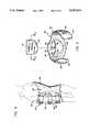
- FIG. 1is a frontal view of a custom in situ formable back brace as fitted on the patient's torso;
- FIG. 2is a side view of an embodiment of the present invention
- FIG. 3is a rear view of a custom formable back brace as fitted on the patient's torso;
- FIG. 4is a side view of an embodiment of the invention.
- FIG. 5is a view of an embodiment of the present invention showing a removable component pad
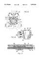
- FIG. 6is a cross-sectional view through Plain VI of FIG. 3 with a detailed showing of a component's structural configuration
- FIG. 7is a cross-sectional view of an alternative structural configuration
- FIG. 8is a cross-sectional view through Plain VIII of FIG. 5 illustrating a component's structure along a patient's spinal recess;
- FIG. 9is a cross-sectional view illustrating an alternative structural configuration
- FIG. 10is a cross-sectional view through Plain X of FIG. 11;
- FIG. 11is a view of an embodiment showing a plurality of detachable component panels in a molded brace frame
- FIG. 12illustrates an embodiment of the invention used on the wearer's torso
- FIG. 13illustrates a further embodiment of the present invention
- FIG. 14is a view of an alternative embodiment incorporating a pneumatic pad
- FIG. 15illustrates yet another embodiment of the present invention
- FIG. 16illustrates a front apron member adaptable for use with several embodiments of the present invention
- FIG. 17is a cross-sectional view through Plain XVII of FIG. 15, with a detailed showing of a mounting means incorporated into the component's structure;
- FIG. 18is a side view of a formable back brace incorporating a means for isolating head and neck movement;
- FIG. 19is a full view of an embodiment of the invention incorporating a means for isolating head and neck movement.
- FIG. 20illustrates an alternative embodiment of the head isolation means.
- FIG. 1shows formable back brace 30 as it is used to support and stabilize the patient's back.
- FIG. 1provides a frontal view of back brace 30 with front component 32 and rear component 34 releasably coupled to the patient's torso and secured by a plurality of securing straps 36.
- the lateral ends of rear component 34preferably overlap the lateral ends of front component 32 while being incrementally tightened about the wearer's torso using straps 36 passing through buckle-loops 38 affixed to front component 32.
- Resilient material 41 interposing adjacent front and rear component panels 33may provide some flexibility of the brace 30 and a high degree of custom fit about the wearer's torso.
- Securing straps 36preferably include Velcro-type mating material allowing for incremental adjustment of the front and rear components 32 and 34 respectively about the torso.
- inlet ports 40are provided on the exterior surfaces of front and rear components 32 and 34.
- a liquid or gas permeable material impregnated with an activatable, hardenable materialis encapsulated within front and rear components 32 and 34 respectively, both of which remain pliable and moldable until liquid is added to the permeable material.
- a predetermined volume of watermay be injected into front and rear components 32 and 34 through inlet ports 40.
- the liquidtypically water, activates the urethane pre-polymer matrix, which causes front and rear components 32 and 34 to harden in the conformed shape of the patient's torso upon completion of the chemical reaction.
- straps 36are of a Velcro-covered type allowing for incremental adjustment of the constraining force of front and rear components 32 and 34 around the torso.
- Velcro-type receiving strips 46are affixed to front component 32 extending between buckle assemblies 38 mounted adjacent to the lateral ends of front component 32. Securing straps 36, with one end fastened to the lateral ends of front component 32, pass through buckle assembly 38 and are received by Velcro-type receiving strips 46.
- FIG. 2shows a side view of an embodiment of the present invention incorporating an alternative securing configuration. Adjustment of the constraining force of brace 30 around the torso is accomplished by tightening securing straps 36 through buckle loop 42. Securing straps 36 are preferably covered with Velcro-type mating material allowing for incremental adjustment of overlapping front and rear components 32 and 34 respectively.
- a rear view of a back brace 30is provided in FIG. 3.
- a plurality of component panels 33comprise rear component 34 with resilient material 41 interposing adjacent component panels 33.
- Inlet ports 40are provided on the exterior surface of each component panel 33 allowing for introduction of liquid to activate the encapsulated hardenable material.
- Component panels 33may be permanently integrated into rear component 34. Alternatively, component panels 33 may be removable, allowing for re-installation of replacement component panels 33 or other structural members of varying rigidity.
- a plurality of securing straps 36are fastened adjacent and along the lateral ends of rear component 34 at attachment sites 44.
- Front and rear components 32 and 34respectively may each be comprised of a single component panel as illustrated in FIG. 4, rather than a plurality of component panels.
- a plurality of inlet ports 40are provided on the exterior surfaces of front and rear components 32 and 34 through which water may be introduced into each component to activate the activatable, hardenable material contained therein.
- the initially pliable front and rear components 32 and 34are respectively coupled to the patient's torso with the lateral ends of rear component 34 preferably overlapping those of front component 32.
- Securing straps 36, passing through buckle loops 42,may be tightened to provide a customized and comfortable fit.
- water or other activating liquidis introduced into front and rear components 32 and 34 through a plurality of inlet ports 40.
- the liquidis transported throughout the interior of front and rear components 32 and 34 thus activating the activatable, hardenable material encapsulated therein.
- the wateractivates the urethane pre-polymer which causes front and rear components 32 and 34 to harden and conform to the unique configuration of the patient's torso, thus providing a custom, in situ formed back support.
- FIG. 5provides a view of an alternative embodiment of the present invention incorporating a formable component pad 50 into a supporting brace 30 preferably constructed from elasticized or resilient fabric generally dimensioned to encircle the lower torso.
- Component pad 50is secured in component pouch 52 by a plurality of Velcro-type securing tabs 58 releasably coupled with corresponding Velcro-type receiving tabs 62 affixed along the periphery of the pouch 52 opening.
- supporting belt brace 30is positioned on the patient's lower torso such that component pad 50 engages the lower back symmetrically about the spine.
- Supporting belt brace 30is securable around the torso using mating Velcro-type securing pads 54. After supporting belt brace 30 is properly secured around the patient's torso, a predetermined volume of liquid is introduced into component pad 50 through inlet port 40, accessed from the exterior of supporting belt brace 30 through port access hole 60.
- component pad 50may be of a construction such that prior to being secured in component pouch 52, component pad 50 is immersed in liquid, preferably water, to activate the hardenable material contained therein. Immediately after being immersed in water, component pad 50 is placed and secured in component pouch 52. Supporting belt brace 30 is then secured to the patient's torso allowing component pad 50 to harden and conform to the unique shape of the lower back region, typically within 3 to 5 minutes.
- FIG. 6is a cross-sectional view through plane VI of FIG. 3.
- a layer of brushed nylon 76forms the interior, or skin-side surface, of back brace 30.
- a layer of foam 78provides ample flexibility as well as cushioning.
- Durable shell 80preferably constructed from durable nylon or other durable flexible material, comprises the exterior shell of front and rear components 32 and 34.
- Component panel 51comprised of activatable, hardenable matrix 72 encapsulated within water impervious enclosure 70, is incorporated into brace 30 between durable shell 80 and durable exterior material 83. Each component panel 51 is properly positioned and secured between stitchings 74 bordering the periphery of each component panel 51.
- Component panels 51may be permanently or removably integrated into back brace 30.
- FIG. 7illustrates a generic hardenable component construction adaptable for use in all back brace 30 configurations.
- Brushed nylon layer 76cushioned by underlying closed cell foam layer 78, covers the interior surface of back brace 30 contacting the patient's skin surface.
- Activatable, hardenable material 72encapsulated within water impervious enclosure 70, remains initially pliable until liquid is introduced into the matrix.
- An additional layer of closed cell foam 78, covered by durable shell layer 80forms the exterior surfaces of back brace 30.
- Durable shell 80may be comprised of durable nylon or other durable polymer material capable of withstanding environmental and mechanical stresses.
- FIG. 8is a cross-sectional view through Plane VIII of component pad 50 of FIG. 5.
- the component construction depicted in FIG. 8is quite similar to that of FIG. 7, but incorporates an additional spinal recess support 82 fashioned from closed cell foam.
- the spinal recess support 82may be incorporated into all back brace 30 embodiments which provides additional support to the spinal area, while inhibiting undesirable shifting of the back brace 30.
- FIG. 9illustrates a cross-sectional view of an alternative component construction adaptable for use in various back brace 30 configurations.
- the activatable, hardenable matrix 72may be impregnated into a layer of fiberglass fibers 87 providing additional structural rigidity.
- Liquidmay be introduced into the component through inlet ports 40 (not shown) which may then be transported through liquid absorbent material 85 to permeate the hardenable matrix 72 distributed throughout the component body.
- Waterproof layers 71confine the activatable materials.
- An additional layer of brushed nylon 76(not shown) may be included to provide additional comfort to the patient.
- a detachable panel assembly 88is depicted in FIG. 10 and is a cross-sectional view through Plane X of FIG. 11.
- Detachable panel assembly 88incorporates at least one component panel 51 comprised of activatable, hardenable matrix 72 encapsulated within water impervious enclosure 70.
- Component panel 51is itself encapsulated within a brushed nylon enclosure 76 with additional closed cell foam 78 providing cushioning to the skin-side interior surface of panel 88.
- a molded brace frame 90is preferably recessed to accept the dimensions of detachable component panel assembly 88.
- a plurality of Velcro-type attachment pads 84, fastened to detachable panel assembly 88,are provided to removably secure each panel within the accepting recesses of molded brace frame 90 via Velcro-type receiving material 86 lining said recessed areas.
- Detachable panel assembly 88may be of a construction allowing easy removal and re-installation of component panel 51 within molded brace frame 90.
- component panel 51may have a structure similar to that illustrated in FIG. 9, and readily adapted to activation by means of immersion in water, rather than by water injection through inlet ports 40 accessed through port access hole 60.
- FIG. 11An alternative embodiment of the present invention is illustrated in FIG. 11.
- a plurality of detachable panel assemblies 88are shown recessed into molded brace frame 90, preferably constructed from closed cell foam.
- the initially pliable, detachable panel assemblies 88are releasably installed into the recesses of molded brace frame 90, and secured therein by a plurality of Velcro-type attachment pads 84 and corresponding Velcro-type receiving material 86 lining the recessed areas.
- Rear component 34is then positioned on the patient's back and preferably secured thereon by a plurality of Velcro-covered securing straps 36 extending circumferentially around the patient's torso, or to an apron arrangement at the front of the patient.
- liquidis introduced into each detachable panel assembly 88 through at least one inlet port 40 externally accessible through port access hole 60.
- rear component 34conforms to the unique configuration of the patient's back.
- a single formable component of moderately complex geometrycomprises the entirety of rear component 34.
- Shoulder protrusions 98, upper protrusions 94, and lower protrusions 95comprise the main structural elements of rear component 34.
- a plurality of securing straps 96, 36, and 92are employed to secure rear component 34 to the patient's back, or by using the apron type structure.
- Shoulder straps 96with one end fastened just above upper protrusions 94, run under each arm, extend over the front shoulder area, and pass through buckle loops 100 affixed to the end of each shoulder protrusion 98, preferably being secured by Velcro-type attachment and receiving material covering shoulder straps 96.
- Shoulder protrusions 98generally extend toward the patient's shoulders from the main body of rear component 34.
- Upper protrusions 94 and lower protrusions 95respectively extend symmetrically from the spinal region toward the sides of the torso.
- a plurality of securing straps 36 and waist strap 92extend around the sides and front of the torso and are detachably coupled, optionally to the apron, by means of Velcro-type mating material covering said straps or other known securing arrangements.
- a plurality of inlet ports 40are provided for introducing water to the activatable, hardenable material contained therein.
- FIG. 13is quite similar to the embodiment illustrated in FIG. 12, differing only in the configuration of shoulder protrusions 98.
- Individual shoulder protrusions 98emanate from upper protrusions 94 extending generally toward the patient's shoulders.
- Shoulder protrusions 98 pictured in FIG. 13provide a greater degree of flexibility and mobility of the upper shoulder and neck area, often required for patient's engaging in recuperative and rehabilitative procedures.
- rear component 34is comprised of a single moldable rear component 102 which incorporates pneumatic pad 104.
- moldable rear component 102may be comprised of a plurality of component panels 33 with resilient material 41 interposing adjacent panels 33 as shown in FIG. 3.
- Pneumatic pad 104may be removably or permanently affixed to the interior surface of moldable rear component 102.
- Pneumatic pad 104may be pre-inflated, and may include inflation and deflation means. Additional foam padding or other resilient material (not shown) may cover pneumatic pad 104 to provide additional comfort and durability.
- a plurality of securing straps 36circumferentially extend around the torso and are secured to apron 120 by Velcro-type mating material covering said straps.
- a plurality of inlet ports 40are provided on the exterior surface of moldable rear component 102 for introducing water to the encapsulated activatable, hardenable material.
- FIG. 15incorporates hardenable upper and lower components 106 and 108 respectively mounted to a pair of semi-rigid support struts 110 generally extending along the patient's spine.
- Support struts 110are preferably fashioned from malleable aluminum, but may be constructed from high-strength engineering plastics or other similar composites.
- Upper and lower components 106 and 108are respectively mounted and secured to support struts 110 by at least one rivet fastener 130 through each strut mount site 112.
- Securing strap pairs 96, 36, and 92respectively extend from support struts 110, circumferentially around the patient's torso, and are secured to apron 120 by means of Velcro-type mating material covering the opposing ends of said strap pairs.
- Inlet ports 40are provided on the exterior surface of upper and lower components 106 and 108 through which liquid may be injected to activate the encapsulated hardenable material.
- FIG. 17shows a cross-sectional view through Plane XVII of lower component 108 pictured in FIG. 15.
- strut mount 112is pictured with rivet 130 passing through support strut 110, hardenable matrix 72, and reinforcement plate 136.
- Reinforcement plate 136may be constructed from high-strength plastic, aluminum, or other rigid material. Moreover, the width and thickness dimensions of reinforcement plate 136 may be the same as, or different from, those of support strut 110. Reinforcement plate 136 may be included to distribute the mechanical load through rivet 130 from the support strut 110, or may be excluded depending on the anticipated stress to strut mount 112. Closed cell foam layer 78 may be recessed to accommodate the thickness of the rivet end 130 and reinforcement plate 136.
- FIG. 16is a showing of front optional apron assembly 120 which may be employed together with several embodiments of the present invention as illustrated in FIGS. 11 through 15.
- securing straps 36extending from rear component 34 and circumferentially around the patient's torso, terminate on Velcro-type receiving straps 128 and Velcro-type receiving pads 124 on apron assembly 120.
- Velcro pads 124the ends of the straps may extend through D-rings and be secured by Velcro back on intermediate sections of the straps.
- Front apron assembly 120is generally dimension to cover the middle chest and abdominal region of the front torso.
- Activatable, hardenable materialis preferably contained within apron component 122, with at least one inlet port 40 provided as a conduit through which water or other liquid may be introduced to activate said hardenable material.
- apron component 122may be detachably affixed to front apron assembly 120 such that it may be easily removed, immersed in water to activate the pre-polymer matrix, re-installed into front apron assembly 120, and secured against the front torso by use of securing straps 36.
- apron component 122hardens and conforms to the patient's mid-section of the front torso.
- a plurality of buckle loops 126are mounted on front apron base 118, with apron base 118 optionally constructed from flexible plastic or other resilient material.
- a plurality of Velcro-type receiving pads 124may be mounted on front apron base 118 to receive securing straps 36 covered with mating Velcro-type material.
- FIG. 18provides a side view of an alternative embodiment of the present invention incorporating neck and head isolation members for patients having severe head and/or neck injuries.
- Front and rear components 32 and 34are shown releasably coupled around the patient's lower torso and secured thereon by at least one pair of securing straps 36 passing through buckle loops 42.
- a plurality of inlet ports 40are distributed over the exterior surfaces of front and rear components 32 and 34.
- the lower end of front strut 138is mounted to front component 32 by a plurality of rivets 130 passing through front strut 138, front strut plate 32, and through hardenable matrix 72 and reinforcement plate 136 (not shown) integrated within front component 32, preferably in a manner similar to that illustrated in FIG.
- Chin support 142is coupled to front strut 138 at strut coupling 140.
- Jaw support members 144on either side of the patient's head, extend from chin support attachment sites 156 to attachment couplings 154 mounted on rear skull components 152.
- Activatable, hardenable materialmay be included within each rear skull component 152, with at least one inlet port 40 provided to facilitate the introduction of water or other liquid into rear skull components 152.
- a pair of rear struts 146are mounted on rear component 34 and extend generally along the patient's spine toward the shoulders.
- Neck support members 148each mounted to attachment couplings 154 fixed on rear skull components 152, are connected to each rear strut 146 by interposed strut couplings 140.
- Rear struts 146are mounted to rear component 34 by a plurality of rivets 130 passing through strut mounts 112 and terminating within rear component 34 preferably in a manner similar to that depicted in FIG. 17.
- FIG. 19is a rotated view of FIG. 18 illustrating the pair of rear struts 146 extending from rear component 134, along the patient's spine to strut couplings 140, and connecting to neck support members 148 which in turn terminate at rear skull components 152.
- An additional layer of padding 153may be included on each rear skull component 152 to provide additional comfort to the patient.
- chin support component 143may be employed to substantially minimize head and neck movement.
- Activatable, hardenable material, contained within chin support component 143may be activated by liquid introduced through at least one inlet port 40.
- chin support component 143hardens and conforms to the unique configuration of the patient's chin and jaw. This embodiment of the present invention is most suited to patient's having severe head and/or neck injuries.
- the number of securing strapsmay be varied from one to several.
- materials other than those describedmay be employed to form hardenable components of differing constructions depending on application requirements.
- Various combinations of materials other than those described hereinabovemay be employed to construct the hardenable components.
- Vinyl or other elastomer and/or fabric materialsmay be employed to form the durable exterior shell.
- Conventional attachment arrangementsmay be used in conjunction with the securing straps to secure the back brace components to the patient's torso.
- front and rear components 32 and 34may be varied to isolate specific portions of the patient's torso, or its entirety.
- pneumatic pad 104may be integrated into front component 32 in combination with, or exclusive of, rear component 34.
- Various other materialssuch as graphite, Kevlar and other fibrous material may comprise hardenable matrix 72 impregnated with a urethane pre-polymer.
- semi-rigid support membersmay be integrated into back brace 30, or may replace one or more component panels 33.
- Molded brace frame 90may be constructed from engineering plastics or other high-strength materials rather than from closed cell foam.
Landscapes
- Health & Medical Sciences (AREA)
- Nursing (AREA)
- Orthopedic Medicine & Surgery (AREA)
- Engineering & Computer Science (AREA)
- Biomedical Technology (AREA)
- Heart & Thoracic Surgery (AREA)
- Vascular Medicine (AREA)
- Life Sciences & Earth Sciences (AREA)
- Animal Behavior & Ethology (AREA)
- General Health & Medical Sciences (AREA)
- Public Health (AREA)
- Veterinary Medicine (AREA)
- Orthopedics, Nursing, And Contraception (AREA)
Abstract
Description
Claims (29)
Priority Applications (2)
| Application Number | Priority Date | Filing Date | Title |
|---|---|---|---|
| US08/017,817US5437614A (en) | 1993-02-16 | 1993-02-16 | Soft-goods type, custom "in situ" formable back support |
| US08/459,463US5632723A (en) | 1993-02-16 | 1995-06-02 | Custom in situ formable brace |
Applications Claiming Priority (1)
| Application Number | Priority Date | Filing Date | Title |
|---|---|---|---|
| US08/017,817US5437614A (en) | 1993-02-16 | 1993-02-16 | Soft-goods type, custom "in situ" formable back support |
Related Child Applications (1)
| Application Number | Title | Priority Date | Filing Date |
|---|---|---|---|
| US08/459,463DivisionUS5632723A (en) | 1993-02-16 | 1995-06-02 | Custom in situ formable brace |
Publications (1)
| Publication Number | Publication Date |
|---|---|
| US5437614Atrue US5437614A (en) | 1995-08-01 |
Family
ID=21784698
Family Applications (2)
| Application Number | Title | Priority Date | Filing Date |
|---|---|---|---|
| US08/017,817Expired - LifetimeUS5437614A (en) | 1993-02-16 | 1993-02-16 | Soft-goods type, custom "in situ" formable back support |
| US08/459,463Expired - LifetimeUS5632723A (en) | 1993-02-16 | 1995-06-02 | Custom in situ formable brace |
Family Applications After (1)
| Application Number | Title | Priority Date | Filing Date |
|---|---|---|---|
| US08/459,463Expired - LifetimeUS5632723A (en) | 1993-02-16 | 1995-06-02 | Custom in situ formable brace |
Country Status (1)
| Country | Link |
|---|---|
| US (2) | US5437614A (en) |
Cited By (56)
| Publication number | Priority date | Publication date | Assignee | Title |
|---|---|---|---|---|
| US5551085A (en)* | 1995-02-07 | 1996-09-03 | Leighton; Adam M. | Lower lumbar support |
| US5632723A (en)* | 1993-02-16 | 1997-05-27 | Royce Medical Company | Custom in situ formable brace |
| FR2742045A1 (en)* | 1995-12-07 | 1997-06-13 | Dobi Symplex Inc | ORTHOPEDIC LEG FRAME AND METHOD OF MANUFACTURE |
| WO1997039704A1 (en)* | 1996-04-24 | 1997-10-30 | Charters John D | Upper body support apparatus |
| US5843009A (en)* | 1991-03-22 | 1998-12-01 | Stojanovic; Branislav | Therapeutic treatment device |
| US5954676A (en)* | 1995-06-07 | 1999-09-21 | Kramer, Iii; Warren G. | Versatile splinting device |
| US6071257A (en)* | 1991-03-22 | 2000-06-06 | Stojanovic; Branislov | Linkably segmented device having protruding contact elements |
| USD435109S (en)* | 1996-01-11 | 2000-12-12 | Branislav Stojanovic | Therapeutic treatment device |
| US6336930B1 (en)* | 2000-03-07 | 2002-01-08 | Zimmer, Inc. | Polymer filled bone plate |
| EP0955966A4 (en)* | 1997-10-02 | 2002-01-30 | Michael D Modglin | Lumbo-sacral orthosis |
| US6419652B1 (en)* | 1999-10-19 | 2002-07-16 | Fla Orthopedics, Inc. | Back belt and method |
| US6478759B1 (en) | 2000-03-09 | 2002-11-12 | Deroyal Industries, Inc. | Thoraco-lumbo-sacral orthosis |
| US6610022B1 (en)* | 2002-08-02 | 2003-08-26 | Terri E. Ashbaugh | Adjustable orthopedic support fastener system |
| US20030220594A1 (en)* | 2002-05-24 | 2003-11-27 | United States Manufacturing Company, Inc. | Torso orthosis apparatus and method |
| US6666838B2 (en) | 2002-04-22 | 2003-12-23 | Deroyal Industries, Inc. | Low-profile lumbo-sacral orthosis |
| US20040059267A1 (en)* | 2002-09-11 | 2004-03-25 | Toni Kancilja | Therapeutic treatment apparatus and method |
| US20040147861A1 (en)* | 2003-01-29 | 2004-07-29 | Kozersky David J. | Orthosis for supporting spinal structures |
| US20040167448A1 (en)* | 2003-02-26 | 2004-08-26 | Heffez Dan S. | Method for lordosis adjustment for treating discomfort in, or originating in, the cervical spine region |
| US20040167449A1 (en)* | 2003-02-26 | 2004-08-26 | Heffez Dan S. | Appliance for lordosis adjustment for treating discomfort in, or originating in, the cervical spine region |
| USD499846S1 (en) | 2004-02-13 | 2004-12-14 | Studio Moderna Sa | Sports belt |
| US20050215930A1 (en)* | 2004-03-29 | 2005-09-29 | Park Dae S | Back immobilizing, dynamically self-adjusting, customizable frame |
| US20050234374A1 (en)* | 2004-04-20 | 2005-10-20 | Grim Tracy E | Splint or support with quick location technique |
| US20050234375A1 (en)* | 2004-04-20 | 2005-10-20 | Royce Medical Company | Splint or support with quick location technique |
| US20050251074A1 (en)* | 2004-05-07 | 2005-11-10 | Latham Mark A | String arrangement of a separate back immobilizing, dynamically self-adjusting, customizing back support for a vertebra related patient |
| USD512779S1 (en) | 2003-03-07 | 2005-12-13 | Studio Moderna Sa | Multi-column therapeutic treatment device |
| US20080173316A1 (en)* | 2007-01-24 | 2008-07-24 | Lloyd Richard E | Emergency transport back support apparatus and method |
| US20090054818A1 (en)* | 2004-06-09 | 2009-02-26 | Mayo Foundation For Medical Education And Research | Spinal orthoses |
| DE102009050385A1 (en)* | 2009-10-22 | 2011-05-05 | Otto Bock Healthcare Gmbh | Device for detecting and / or influencing posture |
| US20110105971A1 (en)* | 2009-11-04 | 2011-05-05 | Arni Thor Ingimundarson | Thoracic lumbar sacral orthosis |
| USD641482S1 (en) | 2010-05-25 | 2011-07-12 | Ossur Hf | Orthosis component |
| USD641483S1 (en) | 2010-05-25 | 2011-07-12 | Ossur Hf | Orthosis component |
| USD677390S1 (en)* | 2011-09-09 | 2013-03-05 | Geoffrey Garth | Panel for a back brace |
| USD689616S1 (en)* | 2011-10-24 | 2013-09-10 | Ki Yong Chang | Support panel for use with waist traction belt |
| USD689617S1 (en)* | 2011-10-24 | 2013-09-10 | Ki Yong Chang | Support panel for use with waist traction belt |
| US20140296653A1 (en)* | 2009-11-03 | 2014-10-02 | Arthur L. Jenkins, III | Dynamically reactive spinal support system |
| US20140309570A1 (en)* | 2013-04-10 | 2014-10-16 | Alfred Health | Chest Brace |
| US8926537B2 (en) | 2009-02-26 | 2015-01-06 | Ossur Hf | Orthopedic device for treatment of the back |
| US9314363B2 (en) | 2013-01-24 | 2016-04-19 | Ossur Hf | Orthopedic device for treating complications of the hip |
| US9370440B2 (en) | 2012-01-13 | 2016-06-21 | Ossur Hf | Spinal orthosis |
| US20160206467A1 (en)* | 2015-01-16 | 2016-07-21 | Corflex, Inc. | Lumbar Brace |
| US9439800B2 (en) | 2009-01-14 | 2016-09-13 | Ossur Hf | Orthopedic device, use of orthopedic device and method for producing same |
| US9468554B2 (en) | 2013-01-24 | 2016-10-18 | Ossur Iceland Ehf | Orthopedic device for treating complications of the hip |
| US20160374891A1 (en)* | 2011-09-29 | 2016-12-29 | Covidien Lp | Compression garment having sealable bladder pocket |
| US9554935B2 (en) | 2013-01-24 | 2017-01-31 | Ossur Hf | Orthopedic device for treating complications of the hip |
| US9572705B2 (en) | 2012-01-13 | 2017-02-21 | Ossur Hf | Spinal orthosis |
| US9795500B2 (en) | 2013-01-24 | 2017-10-24 | Ossur Hf | Orthopedic device for treating complications of the hip |
| US9872794B2 (en) | 2012-09-19 | 2018-01-23 | Ossur Hf | Panel attachment and circumference adjustment systems for an orthopedic device |
| US20180168545A1 (en)* | 2015-06-15 | 2018-06-21 | Cvr Global Inc. | Yoke for sensing carotid stenosis |
| US10159592B2 (en) | 2015-02-27 | 2018-12-25 | Ossur Iceland Ehf | Spinal orthosis, kit and method for using the same |
| US20190192330A1 (en)* | 2017-12-21 | 2019-06-27 | Trevor J. Theriot | Single Pull Lumbar Support Brace |
| US10561520B2 (en) | 2015-02-27 | 2020-02-18 | Ossur Iceland Ehf | Spinal orthosis, kit and method for using the same |
| US11000439B2 (en) | 2017-09-28 | 2021-05-11 | Ossur Iceland Ehf | Body interface |
| US11246734B2 (en) | 2017-09-07 | 2022-02-15 | Ossur Iceland Ehf | Thoracic lumbar sacral orthosis attachment |
| US11324622B1 (en) | 2019-08-08 | 2022-05-10 | Preferred Prescription, Inc. | Back brace belt and apparatus, and method of belt length adjustment therefor |
| US11540934B2 (en)* | 2017-04-28 | 2023-01-03 | Brandeis University | Adjustable back brace and methods for use thereof |
| US12004994B1 (en)* | 2020-12-31 | 2024-06-11 | Restorear Devices, Llc | Device for hypothermia therapy on a cochlea |
Families Citing this family (32)
| Publication number | Priority date | Publication date | Assignee | Title |
|---|---|---|---|---|
| US5713838A (en)* | 1996-07-22 | 1998-02-03 | Termanini; Zafer | Curing of orthopedic casting material and device and method for using same |
| US6099490A (en)* | 1998-10-29 | 2000-08-08 | Turtzo; Craig H. | Support brace |
| US6319217B1 (en)* | 1999-03-10 | 2001-11-20 | Bsn Medical, Inc. | Custom-fitting lumbosacral support pad |
| US6165147A (en)* | 1999-05-19 | 2000-12-26 | Morrow; Kenneth | Lower back and hip support device |
| US6117096A (en)* | 1999-08-19 | 2000-09-12 | Hassard; Peter K. | Lower spine protector |
| US6240923B1 (en) | 1999-11-15 | 2001-06-05 | E. Frederick Barrick | Pelvis immobilizer |
| US6666509B2 (en)* | 2000-03-17 | 2003-12-23 | Honda Access Corp. | Body support tool and seat cover holding body support tool |
| CA2325681C (en)* | 2000-11-10 | 2006-04-18 | Bauer Nike Hockey Inc. | Hockey pants featuring an adjustable dorsal protector |
| FR2817735B1 (en)* | 2000-12-07 | 2003-07-18 | Jean Christophe Christ Mignard | TRUNK PROSTHESIS |
| US20040232745A1 (en)* | 2001-09-10 | 2004-11-25 | Seiya Matsushima | Body supporter |
| WO2003049578A1 (en)* | 2001-12-11 | 2003-06-19 | Honda Access Corporation | Body support device |
| US20030187378A1 (en)* | 2002-04-02 | 2003-10-02 | Gaylord Robert Scott | Medical padding product with adjustable and removable gel pad |
| US7037283B2 (en)* | 2002-10-18 | 2006-05-02 | Ossur Hf | Casting product and method for forming the same |
| US20050015034A1 (en)* | 2003-02-04 | 2005-01-20 | Sansone Joseph Anthony | TMC texas brace |
| US7211031B1 (en)* | 2003-07-18 | 2007-05-01 | Oleg Soloviev | Portable exercise system |
| US7958574B1 (en) | 2006-05-04 | 2011-06-14 | Keith Bodeen | Upper trunk protector and related methods |
| US7597671B2 (en)* | 2007-04-03 | 2009-10-06 | Daniel Robert Baumgartner | Low-temperature reusable thermoplastic splint |
| US10842653B2 (en) | 2007-09-19 | 2020-11-24 | Ability Dynamics, Llc | Vacuum system for a prosthetic foot |
| WO2010124044A2 (en)* | 2009-04-22 | 2010-10-28 | Perfect Pushup Llc | Exercise device |
| US10863791B2 (en) | 2011-04-07 | 2020-12-15 | Ovation Medical | Removable leg walker |
| US20120330376A1 (en)* | 2011-06-27 | 2012-12-27 | Equine OrthoCare, LLC | Systems and methods for making and using electrical stimulation systems for providing therapy to large animals |
| US9248042B2 (en) | 2012-09-12 | 2016-02-02 | Yessenia Lopez | Dorsal foot splint |
| EP2948222B1 (en) | 2013-01-22 | 2021-01-06 | Gorbel, Inc. | Medical rehab lift system with horizontal and vertical force sensing and motion control |
| US10478371B2 (en) | 2013-01-22 | 2019-11-19 | Gorbel, Inc. | Medical rehab body weight support system and method with horizontal and vertical force sensing and motion control |
| US10039664B2 (en) | 2013-03-15 | 2018-08-07 | Ortho Systems | Overmolding for an orthopedic walking boot |
| US10449078B2 (en) | 2013-03-15 | 2019-10-22 | Ovation Medical | Modular system for an orthopedic walking boot |
| WO2014144517A1 (en) | 2013-03-15 | 2014-09-18 | Ovation Medical | Orthopedic walking boot with heel cushion |
| US9510965B2 (en) | 2014-07-01 | 2016-12-06 | Ortho Systems | Adjustable walking apparatus |
| US10398618B2 (en)* | 2015-06-19 | 2019-09-03 | Gorbel, Inc. | Body harness |
| US11246735B2 (en)* | 2016-06-28 | 2022-02-15 | H. Mark Estrada, JR. | Conforming rigid cast, brace and splint comprising a curable polymeric material |
| USD846130S1 (en) | 2018-01-31 | 2019-04-16 | Ortho Systems | Knee brace |
| CN109330756B (en)* | 2018-11-26 | 2020-10-23 | 吉林大学第一医院 | Brace device for fixing lumbar vertebra |
Citations (11)
| Publication number | Priority date | Publication date | Assignee | Title |
|---|---|---|---|---|
| US443764A (en)* | 1890-12-30 | hilliaed | ||
| US3667457A (en)* | 1969-01-23 | 1972-06-06 | Medico Ortopedica Dott Giovann | Orthopaedic apparatus for traction of the spinal column |
| US3945376A (en)* | 1974-12-12 | 1976-03-23 | Otto Bock Orthopedic Industry, Inc. | Orthopedic brace (orthesis) |
| US4475543A (en)* | 1983-01-17 | 1984-10-09 | Brooks William R | Lumbosacral brace |
| US4622957A (en)* | 1984-07-03 | 1986-11-18 | Curlee James D | Therapeutic corset |
| US4628913A (en)* | 1984-01-13 | 1986-12-16 | United States Manufacturing Co. | Cervical thoracic orthosis |
| US4852557A (en)* | 1988-05-24 | 1989-08-01 | Royce Medical Company | Soft-goods type, formable orthopaedic cast |
| US4948092A (en)* | 1990-03-07 | 1990-08-14 | Royce Medical Company | Combined check valve and fluid pressure relief valve |
| US4993409A (en)* | 1989-02-08 | 1991-02-19 | Royce Medical Company | Back support |
| US5062414A (en)* | 1989-02-08 | 1991-11-05 | Royce Medical Company | Simplified orthopaedic back support |
| US5074288A (en)* | 1990-04-11 | 1991-12-24 | Miller Marion E | Soft body brace |
Family Cites Families (1)
| Publication number | Priority date | Publication date | Assignee | Title |
|---|---|---|---|---|
| US5437614A (en)* | 1993-02-16 | 1995-08-01 | Royce Medical Company | Soft-goods type, custom "in situ" formable back support |
- 1993
- 1993-02-16USUS08/017,817patent/US5437614A/ennot_activeExpired - Lifetime
- 1995
- 1995-06-02USUS08/459,463patent/US5632723A/ennot_activeExpired - Lifetime
Patent Citations (11)
| Publication number | Priority date | Publication date | Assignee | Title |
|---|---|---|---|---|
| US443764A (en)* | 1890-12-30 | hilliaed | ||
| US3667457A (en)* | 1969-01-23 | 1972-06-06 | Medico Ortopedica Dott Giovann | Orthopaedic apparatus for traction of the spinal column |
| US3945376A (en)* | 1974-12-12 | 1976-03-23 | Otto Bock Orthopedic Industry, Inc. | Orthopedic brace (orthesis) |
| US4475543A (en)* | 1983-01-17 | 1984-10-09 | Brooks William R | Lumbosacral brace |
| US4628913A (en)* | 1984-01-13 | 1986-12-16 | United States Manufacturing Co. | Cervical thoracic orthosis |
| US4622957A (en)* | 1984-07-03 | 1986-11-18 | Curlee James D | Therapeutic corset |
| US4852557A (en)* | 1988-05-24 | 1989-08-01 | Royce Medical Company | Soft-goods type, formable orthopaedic cast |
| US4993409A (en)* | 1989-02-08 | 1991-02-19 | Royce Medical Company | Back support |
| US5062414A (en)* | 1989-02-08 | 1991-11-05 | Royce Medical Company | Simplified orthopaedic back support |
| US4948092A (en)* | 1990-03-07 | 1990-08-14 | Royce Medical Company | Combined check valve and fluid pressure relief valve |
| US5074288A (en)* | 1990-04-11 | 1991-12-24 | Miller Marion E | Soft body brace |
Cited By (97)
| Publication number | Priority date | Publication date | Assignee | Title |
|---|---|---|---|---|
| US5843009A (en)* | 1991-03-22 | 1998-12-01 | Stojanovic; Branislav | Therapeutic treatment device |
| US6071257A (en)* | 1991-03-22 | 2000-06-06 | Stojanovic; Branislov | Linkably segmented device having protruding contact elements |
| US5632723A (en)* | 1993-02-16 | 1997-05-27 | Royce Medical Company | Custom in situ formable brace |
| US5551085A (en)* | 1995-02-07 | 1996-09-03 | Leighton; Adam M. | Lower lumbar support |
| US5954676A (en)* | 1995-06-07 | 1999-09-21 | Kramer, Iii; Warren G. | Versatile splinting device |
| FR2742045A1 (en)* | 1995-12-07 | 1997-06-13 | Dobi Symplex Inc | ORTHOPEDIC LEG FRAME AND METHOD OF MANUFACTURE |
| FR2745489A1 (en)* | 1995-12-07 | 1997-09-05 | Dobi Symplex Inc | METHOD FOR MANUFACTURING A STRUCTURAL ELEMENT AND ELEMENT THUS OBTAINED |
| BE1012196A5 (en)* | 1995-12-07 | 2000-07-04 | Seattle Orthopedic Group Inc | Leg system for secure and production process. |
| USD435109S (en)* | 1996-01-11 | 2000-12-12 | Branislav Stojanovic | Therapeutic treatment device |
| WO1997039704A1 (en)* | 1996-04-24 | 1997-10-30 | Charters John D | Upper body support apparatus |
| EP0955966A4 (en)* | 1997-10-02 | 2002-01-30 | Michael D Modglin | Lumbo-sacral orthosis |
| US6419652B1 (en)* | 1999-10-19 | 2002-07-16 | Fla Orthopedics, Inc. | Back belt and method |
| US6336930B1 (en)* | 2000-03-07 | 2002-01-08 | Zimmer, Inc. | Polymer filled bone plate |
| AU772701B2 (en)* | 2000-03-07 | 2004-05-06 | Zimmer Technology, Inc. | Polymer filled bone plate |
| US6478759B1 (en) | 2000-03-09 | 2002-11-12 | Deroyal Industries, Inc. | Thoraco-lumbo-sacral orthosis |
| US20030050585A1 (en)* | 2000-03-09 | 2003-03-13 | Modglin Michael D. | Thoraco-lumbo-sacral orthosis |
| US6666838B2 (en) | 2002-04-22 | 2003-12-23 | Deroyal Industries, Inc. | Low-profile lumbo-sacral orthosis |
| US20030220594A1 (en)* | 2002-05-24 | 2003-11-27 | United States Manufacturing Company, Inc. | Torso orthosis apparatus and method |
| US6610022B1 (en)* | 2002-08-02 | 2003-08-26 | Terri E. Ashbaugh | Adjustable orthopedic support fastener system |
| US20040059267A1 (en)* | 2002-09-11 | 2004-03-25 | Toni Kancilja | Therapeutic treatment apparatus and method |
| US7247145B2 (en) | 2002-09-11 | 2007-07-24 | Studio Moderna Sa | Therapeutic treatment apparatus and method |
| US7927297B2 (en) | 2002-09-11 | 2011-04-19 | Studio Moderna Sa | Therapeutic treatment apparatus and method |
| US20070208288A1 (en)* | 2002-09-11 | 2007-09-06 | Studio Moderna Sa | Therapeutic treatment apparatus and method |
| US6840916B2 (en)* | 2003-01-29 | 2005-01-11 | David J. Kozersky | Orthosis for supporting spinal structures |
| US20040147861A1 (en)* | 2003-01-29 | 2004-07-29 | Kozersky David J. | Orthosis for supporting spinal structures |
| US6896662B2 (en) | 2003-02-26 | 2005-05-24 | Dan S. Heffez | Method for lordosis adjustment for treating discomfort in, or originating in, the cervical spine region |
| US20040167448A1 (en)* | 2003-02-26 | 2004-08-26 | Heffez Dan S. | Method for lordosis adjustment for treating discomfort in, or originating in, the cervical spine region |
| US20040167449A1 (en)* | 2003-02-26 | 2004-08-26 | Heffez Dan S. | Appliance for lordosis adjustment for treating discomfort in, or originating in, the cervical spine region |
| USD512779S1 (en) | 2003-03-07 | 2005-12-13 | Studio Moderna Sa | Multi-column therapeutic treatment device |
| USD499846S1 (en) | 2004-02-13 | 2004-12-14 | Studio Moderna Sa | Sports belt |
| US6951547B1 (en)* | 2004-03-29 | 2005-10-04 | Dae Shik Park | Back immobilizing, dynamically self-adjusting, customizable frame |
| US20050215930A1 (en)* | 2004-03-29 | 2005-09-29 | Park Dae S | Back immobilizing, dynamically self-adjusting, customizable frame |
| US20050234375A1 (en)* | 2004-04-20 | 2005-10-20 | Royce Medical Company | Splint or support with quick location technique |
| US20050234374A1 (en)* | 2004-04-20 | 2005-10-20 | Grim Tracy E | Splint or support with quick location technique |
| US20050251074A1 (en)* | 2004-05-07 | 2005-11-10 | Latham Mark A | String arrangement of a separate back immobilizing, dynamically self-adjusting, customizing back support for a vertebra related patient |
| US7083585B2 (en)* | 2004-05-07 | 2006-08-01 | Mark Alan Latham | String arrangement of a separate back immobilizing, dynamically self-adjusting, customizing back support for a vertebra related patient |
| US20090054818A1 (en)* | 2004-06-09 | 2009-02-26 | Mayo Foundation For Medical Education And Research | Spinal orthoses |
| WO2006137962A3 (en)* | 2005-06-14 | 2007-11-15 | Ossur Hf | Splint or support with quick location technique |
| US20080173316A1 (en)* | 2007-01-24 | 2008-07-24 | Lloyd Richard E | Emergency transport back support apparatus and method |
| US8991400B2 (en) | 2007-01-24 | 2015-03-31 | Richard E. Lloyd | Emergency transport back support apparatus and method |
| US9439800B2 (en) | 2009-01-14 | 2016-09-13 | Ossur Hf | Orthopedic device, use of orthopedic device and method for producing same |
| US12127965B2 (en) | 2009-02-26 | 2024-10-29 | Ossur Hf | Orthopedic device for treatment of the back |
| US10828186B2 (en) | 2009-02-26 | 2020-11-10 | Ossur Hf | Orthopedic device for treatment of the back |
| US9414953B2 (en) | 2009-02-26 | 2016-08-16 | Ossur Hf | Orthopedic device for treatment of the back |
| US8945034B2 (en) | 2009-02-26 | 2015-02-03 | Ossur Hf | Orthopedic device for treatment of the back |
| US8926537B2 (en) | 2009-02-26 | 2015-01-06 | Ossur Hf | Orthopedic device for treatment of the back |
| DE102009050385A1 (en)* | 2009-10-22 | 2011-05-05 | Otto Bock Healthcare Gmbh | Device for detecting and / or influencing posture |
| US11013631B2 (en)* | 2009-11-03 | 2021-05-25 | Arthur L. Jenkins, III | Dynamically reactive spinal support system |
| US20140296653A1 (en)* | 2009-11-03 | 2014-10-02 | Arthur L. Jenkins, III | Dynamically reactive spinal support system |
| US8657769B2 (en) | 2009-11-04 | 2014-02-25 | Ossur Hf | Thoracic lumbar sacral orthosis |
| US20110105971A1 (en)* | 2009-11-04 | 2011-05-05 | Arni Thor Ingimundarson | Thoracic lumbar sacral orthosis |
| US9220625B2 (en) | 2009-11-04 | 2015-12-29 | Ossur Hf | Thoracic lumbar sacral orthosis |
| US10617552B2 (en) | 2009-11-04 | 2020-04-14 | Ossur Hf | Thoracic lumbar sacral orthosis |
| US9597219B2 (en) | 2009-11-04 | 2017-03-21 | Ossur Hf | Thoracic lumbar sacral orthosis |
| USD641482S1 (en) | 2010-05-25 | 2011-07-12 | Ossur Hf | Orthosis component |
| USD641483S1 (en) | 2010-05-25 | 2011-07-12 | Ossur Hf | Orthosis component |
| USD652937S1 (en) | 2010-05-25 | 2012-01-24 | Ossur Hf | Orthosis component |
| USD677390S1 (en)* | 2011-09-09 | 2013-03-05 | Geoffrey Garth | Panel for a back brace |
| US10342730B2 (en)* | 2011-09-29 | 2019-07-09 | Kpr U.S., Llc | Compression garment having sealable bladder pocket |
| US20160374891A1 (en)* | 2011-09-29 | 2016-12-29 | Covidien Lp | Compression garment having sealable bladder pocket |
| USD689617S1 (en)* | 2011-10-24 | 2013-09-10 | Ki Yong Chang | Support panel for use with waist traction belt |
| USD689616S1 (en)* | 2011-10-24 | 2013-09-10 | Ki Yong Chang | Support panel for use with waist traction belt |
| US9370440B2 (en) | 2012-01-13 | 2016-06-21 | Ossur Hf | Spinal orthosis |
| US9572705B2 (en) | 2012-01-13 | 2017-02-21 | Ossur Hf | Spinal orthosis |
| US12186226B2 (en) | 2012-01-13 | 2025-01-07 | Ossur Hf | Spinal orthosis |
| US10898365B2 (en) | 2012-01-13 | 2021-01-26 | Ossur Hf | Spinal orthosis |
| US11484428B2 (en) | 2012-09-19 | 2022-11-01 | Ossur Hf | Panel attachment and circumference adjustment systems for an orthopedic device |
| US9872794B2 (en) | 2012-09-19 | 2018-01-23 | Ossur Hf | Panel attachment and circumference adjustment systems for an orthopedic device |
| US10980657B2 (en) | 2012-09-19 | 2021-04-20 | Ossur Hf | Panel attachment and circumference adjustment systems for an orthopedic device |
| US9795500B2 (en) | 2013-01-24 | 2017-10-24 | Ossur Hf | Orthopedic device for treating complications of the hip |
| US9314363B2 (en) | 2013-01-24 | 2016-04-19 | Ossur Hf | Orthopedic device for treating complications of the hip |
| US12433778B2 (en) | 2013-01-24 | 2025-10-07 | Ossur Hf | Orthopedic device for treating complications of the hip |
| US11259948B2 (en) | 2013-01-24 | 2022-03-01 | Ossur Hf | Orthopedic device for treating complications of the hip |
| US10357391B2 (en) | 2013-01-24 | 2019-07-23 | Ossur Hf | Orthopedic device for treating complications of the hip |
| US9468554B2 (en) | 2013-01-24 | 2016-10-18 | Ossur Iceland Ehf | Orthopedic device for treating complications of the hip |
| US9554935B2 (en) | 2013-01-24 | 2017-01-31 | Ossur Hf | Orthopedic device for treating complications of the hip |
| US9393144B2 (en) | 2013-01-24 | 2016-07-19 | Ossur Hf | Orthopedic device for treating complications of the hip |
| US9987158B2 (en) | 2013-01-24 | 2018-06-05 | Ossur Hf | Orthopedic device for treating complications of the hip |
| US20140309570A1 (en)* | 2013-04-10 | 2014-10-16 | Alfred Health | Chest Brace |
| US20160206467A1 (en)* | 2015-01-16 | 2016-07-21 | Corflex, Inc. | Lumbar Brace |
| US10143583B2 (en)* | 2015-01-16 | 2018-12-04 | Corflex, Inc. | Lumbar brace |
| US10159592B2 (en) | 2015-02-27 | 2018-12-25 | Ossur Iceland Ehf | Spinal orthosis, kit and method for using the same |
| US10561520B2 (en) | 2015-02-27 | 2020-02-18 | Ossur Iceland Ehf | Spinal orthosis, kit and method for using the same |
| US11273064B2 (en) | 2015-02-27 | 2022-03-15 | Ossur Iceland Ehf | Spinal orthosis, kit and method for using the same |
| US11571323B2 (en) | 2015-02-27 | 2023-02-07 | Ossur Iceland Ehf | Spinal orthosis, kit and method for using the same |
| US20180168545A1 (en)* | 2015-06-15 | 2018-06-21 | Cvr Global Inc. | Yoke for sensing carotid stenosis |
| US11911211B2 (en)* | 2015-06-15 | 2024-02-27 | Cvr Medical Corporation | Yoke for sensing carotid stenosis |
| US11540934B2 (en)* | 2017-04-28 | 2023-01-03 | Brandeis University | Adjustable back brace and methods for use thereof |
| US11684506B2 (en) | 2017-09-07 | 2023-06-27 | Ossur Iceland Ehf | Thoracic lumbar sacral orthosis attachment |
| US12090079B2 (en) | 2017-09-07 | 2024-09-17 | Ossur Iceland Ehf | Thoracic lumbar sacral orthosis attachment |
| US11246734B2 (en) | 2017-09-07 | 2022-02-15 | Ossur Iceland Ehf | Thoracic lumbar sacral orthosis attachment |
| US11850206B2 (en) | 2017-09-28 | 2023-12-26 | Ossur Iceland Ehf | Body interface |
| US11000439B2 (en) | 2017-09-28 | 2021-05-11 | Ossur Iceland Ehf | Body interface |
| US20190192330A1 (en)* | 2017-12-21 | 2019-06-27 | Trevor J. Theriot | Single Pull Lumbar Support Brace |
| US11324622B1 (en) | 2019-08-08 | 2022-05-10 | Preferred Prescription, Inc. | Back brace belt and apparatus, and method of belt length adjustment therefor |
| US12357490B2 (en) | 2019-08-08 | 2025-07-15 | Preferred Prescription, Inc. | Back brace with enhanced height support and adjustment capability |
| US12004994B1 (en)* | 2020-12-31 | 2024-06-11 | Restorear Devices, Llc | Device for hypothermia therapy on a cochlea |
Also Published As
| Publication number | Publication date |
|---|---|
| US5632723A (en) | 1997-05-27 |
Similar Documents
| Publication | Publication Date | Title |
|---|---|---|
| US5437614A (en) | Soft-goods type, custom "in situ" formable back support | |
| US5554104A (en) | Custom formable knee brace | |
| US5853378A (en) | Lumbo-Sacral orthosis | |
| US5358470A (en) | Shoulder immobilization restraint | |
| EP0735847B1 (en) | Derotating orthotic devices for the correction of scoliotic deformities | |
| US5840050A (en) | Post-operative hip brace | |
| US4844094A (en) | Ankle brace | |
| CA2627669C (en) | Fracture brace | |
| US5295947A (en) | Chiropractic brace | |
| US6494854B1 (en) | Cervical collar device | |
| US5383844A (en) | Humeral fracture brace | |
| US5360394A (en) | Rigid joint support brace sizing means and method | |
| US5503621A (en) | Body brace | |
| CA2170058C (en) | Patella stabilizer | |
| EP0770368B1 (en) | Walker brace | |
| CA2185486C (en) | Industrial back support | |
| US5344391A (en) | Hip abduction system | |
| JP2568446B2 (en) | Flexible shape following orthopedic cast | |
| US5464383A (en) | Device for supporting and immobilizing a patient's arm and shoulder and method therefor | |
| US4907575A (en) | Ambulatory lumbar traction device | |
| US20050020950A1 (en) | Arm sling apparatus allowing movement or total immobilization | |
| US20060079821A1 (en) | Spinal orthosis | |
| JPS6122579B2 (en) | ||
| US20230010304A1 (en) | Adjustable neck rehabilitation and exercise device and method for use | |
| KR101801868B1 (en) | Scoliosis brace |
Legal Events
| Date | Code | Title | Description |
|---|---|---|---|
| AS | Assignment | Owner name:ROYCE MEDICAL COMPANY, CALIFORNIA Free format text:ASSIGNMENT OF ASSIGNORS INTEREST.;ASSIGNOR:GRIM, TRACY E.;REEL/FRAME:006436/0937 Effective date:19930209 | |
| STCF | Information on status: patent grant | Free format text:PATENTED CASE | |
| FEPP | Fee payment procedure | Free format text:PAYOR NUMBER ASSIGNED (ORIGINAL EVENT CODE: ASPN); ENTITY STATUS OF PATENT OWNER: SMALL ENTITY | |
| FPAY | Fee payment | Year of fee payment:4 | |
| AS | Assignment | Owner name:U.S. BANK NATIONAL ASSOCIATION, CALIFORNIA Free format text:SECURITY INTEREST;ASSIGNOR:ROYCE MEDICAL COMPANY;REEL/FRAME:010742/0926 Effective date:20000406 | |
| FPAY | Fee payment | Year of fee payment:8 | |
| AS | Assignment | Owner name:ANTARES CAPITAL CORPORATION, AS AGENT, ILLINOIS Free format text:SECURITY AGREEMENT;ASSIGNOR:ROYCE MEDICAL COMPANY;REEL/FRAME:014313/0001 Effective date:20030711 | |
| AS | Assignment | Owner name:ROYCE MEDICAL COMPANY, CALIFORNIA Free format text:PATENT RELEASE AND REASSIGNMENT;ASSIGNOR:ANTARES CAPITAL CORPORATION;REEL/FRAME:016408/0753 Effective date:20050810 | |
| AS | Assignment | Owner name:KAUPTHING BANK HF, NEW YORK Free format text:SECURITY AGREEMENT;ASSIGNOR:ROYCE MEDICAL COMPANY;REEL/FRAME:016610/0376 Effective date:20050901 | |
| FPAY | Fee payment | Year of fee payment:12 | |
| AS | Assignment | Owner name:OSSUR HF, ICELAND Free format text:ASSIGNMENT OF ASSIGNORS INTEREST;ASSIGNOR:ROYCE MEDICAL COMPANY;REEL/FRAME:019028/0284 Effective date:20070308 |