US5437604A - Nonsurgical intraurethral bladder control device - Google Patents
Nonsurgical intraurethral bladder control deviceDownload PDFInfo
- Publication number
- US5437604A US5437604AUS08/298,033US29803394AUS5437604AUS 5437604 AUS5437604 AUS 5437604AUS 29803394 AUS29803394 AUS 29803394AUS 5437604 AUS5437604 AUS 5437604A
- Authority
- US
- United States
- Prior art keywords
- pressure
- valve
- proximal end
- distal end
- retriever
- Prior art date
- Legal status (The legal status is an assumption and is not a legal conclusion. Google has not performed a legal analysis and makes no representation as to the accuracy of the status listed.)
- Expired - Lifetime
Links
- 238000007915intraurethral administrationMethods0.000titledescription5
- 210000003708urethraAnatomy0.000claimsabstractdescription48
- 239000000523sampleSubstances0.000claimsdescription37
- 239000000314lubricantSubstances0.000claimsdescription24
- 239000012530fluidSubstances0.000claimsdescription12
- 238000004513sizingMethods0.000claimsdescription3
- 210000001519tissueAnatomy0.000abstractdescription8
- 230000004118muscle contractionEffects0.000abstractdescription5
- 230000002706hydrostatic effectEffects0.000abstractdescription2
- 206010056948Automatic bladderDiseases0.000abstract1
- 230000000712assemblyEffects0.000abstract1
- 238000000429assemblyMethods0.000abstract1
- 230000003993interactionEffects0.000abstract1
- 238000001356surgical procedureMethods0.000abstract1
- 210000002700urineAnatomy0.000description15
- 230000008602contractionEffects0.000description9
- 210000003205muscleAnatomy0.000description5
- 238000003780insertionMethods0.000description4
- 230000037431insertionEffects0.000description4
- 230000001050lubricating effectEffects0.000description4
- 239000000463materialSubstances0.000description4
- 238000000034methodMethods0.000description4
- 210000005070sphincterAnatomy0.000description4
- 239000011800void materialSubstances0.000description4
- 210000000683abdominal cavityAnatomy0.000description3
- 230000007423decreaseEffects0.000description3
- 239000007788liquidSubstances0.000description3
- 206010011224CoughDiseases0.000description2
- 238000009434installationMethods0.000description2
- 125000006850spacer groupChemical group0.000description2
- 208000003443UnconsciousnessDiseases0.000description1
- 230000004676abdominal muscle contractionEffects0.000description1
- 230000015572biosynthetic processEffects0.000description1
- 230000003247decreasing effectEffects0.000description1
- 238000010586diagramMethods0.000description1
- 238000005755formation reactionMethods0.000description1
- 238000002513implantationMethods0.000description1
- 230000013011matingEffects0.000description1
- 230000000153supplemental effectEffects0.000description1
- 230000002459sustained effectEffects0.000description1
Images


Classifications
- A—HUMAN NECESSITIES
- A61—MEDICAL OR VETERINARY SCIENCE; HYGIENE
- A61F—FILTERS IMPLANTABLE INTO BLOOD VESSELS; PROSTHESES; DEVICES PROVIDING PATENCY TO, OR PREVENTING COLLAPSING OF, TUBULAR STRUCTURES OF THE BODY, e.g. STENTS; ORTHOPAEDIC, NURSING OR CONTRACEPTIVE DEVICES; FOMENTATION; TREATMENT OR PROTECTION OF EYES OR EARS; BANDAGES, DRESSINGS OR ABSORBENT PADS; FIRST-AID KITS
- A61F2/00—Filters implantable into blood vessels; Prostheses, i.e. artificial substitutes or replacements for parts of the body; Appliances for connecting them with the body; Devices providing patency to, or preventing collapsing of, tubular structures of the body, e.g. stents
- A61F2/0004—Closure means for urethra or rectum, i.e. anti-incontinence devices or support slings against pelvic prolapse
- A61F2/0022—Closure means for urethra or rectum, i.e. anti-incontinence devices or support slings against pelvic prolapse placed deep in the body opening
- A—HUMAN NECESSITIES
- A61—MEDICAL OR VETERINARY SCIENCE; HYGIENE
- A61B—DIAGNOSIS; SURGERY; IDENTIFICATION
- A61B90/00—Instruments, implements or accessories specially adapted for surgery or diagnosis and not covered by any of the groups A61B1/00 - A61B50/00, e.g. for luxation treatment or for protecting wound edges
- A61B90/06—Measuring instruments not otherwise provided for
- Y—GENERAL TAGGING OF NEW TECHNOLOGICAL DEVELOPMENTS; GENERAL TAGGING OF CROSS-SECTIONAL TECHNOLOGIES SPANNING OVER SEVERAL SECTIONS OF THE IPC; TECHNICAL SUBJECTS COVERED BY FORMER USPC CROSS-REFERENCE ART COLLECTIONS [XRACs] AND DIGESTS
- Y10—TECHNICAL SUBJECTS COVERED BY FORMER USPC
- Y10T—TECHNICAL SUBJECTS COVERED BY FORMER US CLASSIFICATION
- Y10T137/00—Fluid handling
- Y10T137/7722—Line condition change responsive valves
- Y10T137/7738—Pop valves
- Y—GENERAL TAGGING OF NEW TECHNOLOGICAL DEVELOPMENTS; GENERAL TAGGING OF CROSS-SECTIONAL TECHNOLOGIES SPANNING OVER SEVERAL SECTIONS OF THE IPC; TECHNICAL SUBJECTS COVERED BY FORMER USPC CROSS-REFERENCE ART COLLECTIONS [XRACs] AND DIGESTS
- Y10—TECHNICAL SUBJECTS COVERED BY FORMER USPC
- Y10T—TECHNICAL SUBJECTS COVERED BY FORMER US CLASSIFICATION
- Y10T137/00—Fluid handling
- Y10T137/7722—Line condition change responsive valves
- Y10T137/7781—With separate connected fluid reactor surface
- Y10T137/7832—Plural valves biased closed
- Y—GENERAL TAGGING OF NEW TECHNOLOGICAL DEVELOPMENTS; GENERAL TAGGING OF CROSS-SECTIONAL TECHNOLOGIES SPANNING OVER SEVERAL SECTIONS OF THE IPC; TECHNICAL SUBJECTS COVERED BY FORMER USPC CROSS-REFERENCE ART COLLECTIONS [XRACs] AND DIGESTS
- Y10—TECHNICAL SUBJECTS COVERED BY FORMER USPC
- Y10T—TECHNICAL SUBJECTS COVERED BY FORMER US CLASSIFICATION
- Y10T137/00—Fluid handling
- Y10T137/7722—Line condition change responsive valves
- Y10T137/7837—Direct response valves [i.e., check valve type]
- Y10T137/7838—Plural
- Y10T137/7846—Mechanically interconnected
- Y—GENERAL TAGGING OF NEW TECHNOLOGICAL DEVELOPMENTS; GENERAL TAGGING OF CROSS-SECTIONAL TECHNOLOGIES SPANNING OVER SEVERAL SECTIONS OF THE IPC; TECHNICAL SUBJECTS COVERED BY FORMER USPC CROSS-REFERENCE ART COLLECTIONS [XRACs] AND DIGESTS
- Y10—TECHNICAL SUBJECTS COVERED BY FORMER USPC
- Y10T—TECHNICAL SUBJECTS COVERED BY FORMER US CLASSIFICATION
- Y10T137/00—Fluid handling
- Y10T137/8593—Systems
- Y10T137/87917—Flow path with serial valves and/or closures
- Y10T137/87981—Common actuator
- Y10T137/87989—Delivery cock with terminal valve
Definitions
- the present inventiongenerally relates to the field of medical devices and more particularly to bladder control devices, and still more particularly to an intraurethral bladder control apparatus commonly referred to as an artificial sphincter.
- Some of the problems and disadvantages found in the prior artinclude: the need for surgical implantation and removal of the device in the urethra; the susceptibility of the device to leakage or to undesired valve openings; the failure of the valve device to stay open long enough to provide complete emptying of the bladder; and in some prior art devices the need for an additional external product, such as a magnet, to actuate the valve device.
- an improved intraurethral bladder control apparatuswhich includes a valve assembly, and a valve assembly mount for releasibly holding the assembly and adapted to be nonsurgically placed and releasibly held in the urethra of a patient.
- the mountis provided with a textured outer surface to which urethral tissue will conform to hold the mount at a selected position therein.
- the valve assemblycooperates with apparatus in an inner chamber of the mount for releasable installation of the assembly.
- the mountis preferably generally cylindrical in shape with a generally cylindrical inner chamber or lumen where valve assembly holding apparatus is deployed.
- Each of the preferred embodiments of the valve assemblyhas adjustment apparatus operable whether the assembly is in the valve assembly mount or not, for positioning the assembly and for setting desired values of the opening and closing the valve, and for a fail-safe mode which is a feature of each preferred embodiment.
- Each preferred embodiment of the present inventionalso includes apparatus for assuring that once opened by the patient's own abdominal muscle contraction, the valve stays open for a sufficient time to empty the bladder, and then closes without further action by the patient.
- a first preferred embodimentincludes a design to utilize Bernoulli's principle to provide a negative pressure that holds the valve open during fluid flow, and a second preferred embodiment is designed to utilize a valve area enlargement during fluid flow to keep the valve open.
- Additional apparatus for sizing the mount, and for inserting and removing the mountis incorporated into this invention.
- Pressure apparatus for providing either a liquid, jell or a gas lubricant under pressureis part of this additional apparatus.
- a number of probes of various sizes, each of which have a lumen extending from the proximal end to sets of aligned holes spaced about the circumference near the distal end,provide a passage for the lubricant.
- the pressure apparatusis attached to the proximal end of a probe. This provides lubricant about the distal end of the probe. This lubricant aids in inserting probes into the urethral opening in sequence, from the smallest size to the largest size the urethra will accept, to determine the urethra size. This information is necessary to determine the proper mount size.
- This same pressure apparatusis used to provide pressurized lubricant adjacent to the base of the mount for placing the mount within the urethra or for removing the mount from the urethra.
- a retrieverwhich threads into a mating hole in the base of the mount, has a shoulder at its distal end adjacent to the mount.
- the retrieverhas a lumen from the proximal end which communicates with holes spaced about the circumference of the shoulder.
- the retrieverhas means at the proximal end for connecting the pressure apparatus. With the pressure apparatus connected to the proximal end of the retriever and the retriever threaded into the base of the mount, the retriever can introduce lubricant under pressure at the base of the mount.
- a sleeve with flanges near each endslideably encircles the retriever.
- This sleevewhen placed over the retriever and pressed against the patient's body, will seal the pressurized lubricant within the urethra.
- This pressurized lubricantwill expand the urethra from the base of the mount inward. This will free the urethra from the textured outer surface of the mount for insertion or removal.
- the pressurized lubricantwill also flow from the base of the mount into this expanded area around the mount to provide lubricant for insertion or removal of the mount. This process is particularly critical when removing the mount, since the walls of the urethra adhere to and tightly engage the textured walls of the mount after installation.
- FIG. 1is a partial sectional view of a first embodiment of the intraurethral bladder control apparatus of this invention with the valve closed;
- FIG. 2is a cross-sectional view of FIG. 1 taken along the line 1--1;
- FIG. 3is another cross-sectional view of FIG. 1 taken along the line 2--2;
- FIG. 4is yet another cross-sectional view of FIG. 1 taken along the line 3--3;
- FIG. 5is a partial sectional view of the embodiment of FIG. 1 with the valve open;
- FIG. 6is a cross-sectional view of a second embodiment of the apparatus of this invention with the valve closed;
- FIG. 7is another cross-sectional view of the embodiment of FIG. 6 with the valve open;
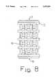
- FIG. 8is a plan view of the valve assembly mount of this invention.
- FIG. 9is a plan view of a valve assembly of this invention.
- FIG. 10is a plan view of pressure apparatus of this invention.
- FIG. 11is a side view of a retriever
- FIG. 11Ais an end view of the retriever's distal end.
- FIG. 12is a side view of a probe
- FIG. 12Ais a cross-sectional view of FIG. 12 taken along the line A--A.
- FIG. 13is a fragmentary view of a patient showing the bladder and urethra in cross-section, with a mount, retriever and sleeve in place within the urethra, and with the proximal end of the retriever connected to the distal end of the distal hose of the pressure apparatus;
- FIG. 14is a fragmentary view of a patient showing the bladder and urethra in cross-section, with a probe in place within the urethra, and with the proximal end of the probe connected to the distal end of the distal hose of the pressure apparatus;
- FIG. 15is a side view of the sleeve
- FIG. 15Ais the end view of the sleeve's distal end
- FIG. 16is a pressure versus time diagram for three different probes.
- FIG. 8there is shown a valve assembly mount 2 in the preferred form of a cylinder having a textured outer surface 16 designed to interact with urethral tissues such that mount 2 may be nonsurgically and releasibly positioned in a patient's urethra.
- Mount 2includes a valve orifice indicated at 11 and adapted to be positioned adjacent the patient's bladder exit, and an assembly orifice indicated at 19 adapted to receive a valve assembly for internal mounting.
- the interior of mount 2includes connection apparatus for releasibly and adjustably mounting a valve assembly.
- mount 2is positioned in the patient's urethra first, left for a period of time to enable the urethra tissue to conform to the textured outer surface 16 of mount 2 to hold mount 2 securely in place, and then a valve assembly is mounted in mount 2.
- FIG. 9there is shown a valve block 33 adapted to releasibly receive a valve apparatus in a manner fully described below with reference to other figures of the drawings.
- Block 33is shown as preferably having a threaded outer surface designed to match a threaded inner surface (not shown in FIG. 8) of mount 2.
- Block 33also has a valve orifice indicated at 21 for alignment adjacent to orifice 11 of mount 2, and an apparatus receiving orifice indicated at 29 for insertion of a valve apparatus.
- an adjustment device 10 having lock notches 9will be available outside block 33.
- device 10may be rotated to make a plurality of adjustments more fully described below with reference to other figures of the drawings.
- FIG. 1there is shown a first embodiment of the bladder control apparatus 1 of this invention, including cylindrical valve assembly mount 2 having textured outer surface 16 and a valve assembly 20 which is threaded into mount 2 by means of a connection thread 15.
- Valve assembly 20includes a valve block 13, a valve 17, a valve orifice 11, a valve ring 7 having a valve area 12, a coiled spring or other biasing apparatus 4, a spacer 6, a stationary ring 3, a fluid passage 8, a bias adjustment apparatus 5, a thread 14 joining bias adjustment apparatus 5 to block 13, and adjustment device 10 having locking notches 9.
- FIGS. 2, 3 and 4respectively taken along the lines 1--1, 2--2 and 3--3, more clearly depict the inner structure of device 1 of FIG. 1, clarifying the positioning and formations of valve 17, spring coil biasing device 4, bias adjustment means 5 with thread 14, fluid passages 8, stationary ring 3 and spacers 6.
- valve 17is in the closed position in orifice 11, thus preventing the flow of urine fluids from the bladder.
- valve 17is shown in the open position, removed from orifice 11, and a plurality of lines with arrows depict the fluid flow path through valve block 13.
- valve assembly mount 2is first inserted into a urethra and allowed to stay for a period of time (usually a few weeks) sufficient for the urethral tissue to conform to the textured outer surface 16 to thus essentially immobilize mount 2. After mount 2 is firmly held by the tissue, a valve assembly such as assembly 20 of FIG. 1 is inserted into the internal chamber or lumen of mount 2 where it is connected and adjusted.
- FIGS. 1-5which utilize Bernoulli's principle to retain the valve in an open position
- assembly 20has been mounted in the lumen of assembly mount 2 which has been immobilized in the patient's urethra in the manner described above.
- Block 13is then adjusted within mount 2 such that orifice 11 passes through orifice 21, as shown in FIG. 8, to align with the output from the patient's bladder (not shown).
- the resulting growth in the urine columnexerts greater pressure on valve 17 through orifice 11 and at the same time the resulting growth in volume within the bladder stimulates the patient's need to void.
- valve assembly 20To initiate the voiding process the patient need only contract the muscles of the lower abdominal cavity for a short period of a few seconds. This short period of contraction will increase the pressure on valve 17 long enough for it to move against the bias of spring 4 and thus begin the flow of urine through valve assembly 20 along the path shown by the arrows in FIG. 5.
- valve 17moves toward valve stop or rest 6.
- Rest 6is a vertical element extending radially for separating the lower surface of valve ring 7 from stationary ring 3.
- the urinethen flows around the edge of valve ring 7 and between the lower surface of ring 7 and stationary ring 3, such that a negative pressure is induced according to Bernoulli's principle between these two surfaces.
- This negative forceovercomes the tension of spring 4 and holds ring 7 down against stop 6, thus holding valve 17 open, as long as a sufficient flow of urine is present.
- the negative forceis decreased until the bias from spring 4 can again close valve 17 in orifice 11 to cut off the flow entirely.
- valve assembly 20has been opened by muscle contraction to allow fluid flow through block 13
- the application of Bernoulli's lawwill automatically prevent closure of valve 17 without further muscle contraction until the bladder has emptied enough to significantly reduce the urine flow; and then the valve assembly will automatically close without further muscle effort.
- the patient's need to voidwill have been met by a simple, short initial contraction of the muscles of the lower abdominal cavity.
- the force with which valve 17 is held closed or seated in orifice 11is determined by the tension from spring 4, which may be any form of bias device.
- This tension or biasis adjusted by bias adjustment apparatus 5, best seen in FIGS. 1 and 3.
- an adjustment tool(not shown) is passed through the urethra to grasp and lock into notches 9 of adjustment device 10.
- Device 10is then selectively rotated which rotates valve 17 and bias adjustment means 5. The rotation of means 5 causes it to move up or down thread 14 to increase or decrease the tension of spring 4.
- valve 17in the direction of reduced bias from coil 4 will eventually disable bladder control device 1 by removing valve 17 from is seat in orifice 11 to allow a free flow of fluid through block 13. Further rotation after reaching the point of free flow will cause rotation of block 13 to first change its positioning within mount 2 and eventually to cause it to disengage from mount 2 entirely. Replacement of block 13 into mount 2 is accomplished by simply reversing the direction of rotation of device 10.
- FIGS. 6-7The above description of the structure and operation of the preferred embodiment of FIGS. 1-3 which utilizes Bernoulli's law is applicable to patients who have a sufficiently rapid rate and volume of urine flow. These values can be clinically determined. If it is found that the patient does not meet the requirements for the use of the above described embodiment, the second preferred embodiment of this invention as described in FIGS. 6-7 can be used.
- FIG. 6again shows a valve assembly mount 2 in which a valve block 43 is removably positioned through use of threads 15.
- a valve 47abuts against an orifice 41 and is maintained in the closed position by a coil spring or other bias device 4.
- valve 47has a valve ring 27 with a valve surface area 42 significantly greater than the area of orifice 41.
- Coil 4abuts against bias adjustment device 25 which is connected to block 43 via thread 44.
- Valve 47is connected to adjustment device 10 which again carries locking notches 9. Fluid passages 28 are provided to pass urine through block 43 along a desired path.
- valve 47is shown as biased against orifice 43, thus closing valve block 43 to prevent urine flow.
- valve 17is shown in the open position and the flow of urine through block 43 is depicted by the arrows.
- mount 2will have first been secured in the patient's urethra in the nonsurgical, removable manner described above with regard to FIGS. 1-5.
- the urethral tissuewill have conformed to surface 16 to hold mount 2 in place.
- Block 43will then be threaded into mount 2 to place orifice 41 in the urethra adjacent to the patient's bladder.
- the bladderfills the urine column will place increased pressure on valve 47 through orifice 41, as well as causing a need to void in the patient.
- the patientagain need only contract the muscles of the lower abdominal cavity for a few seconds. This short period of contraction will cause sufficient pressure for valve 47 to open against the tension of coil spring 4.
- valve 47As soon as valve 47 opens, the urine flow through orifice 41 will impinge on the full surface area 42 of valve ring 27, and since this area is greater than the area of orifice 41, valve 47 will remain open even after the contractions are released, until the urine column has been reduced to an acceptable small amount.
- valve ring 27 and orifice 41can be designed to follow the fact that if valve area increases n times, the pressure may decrease n times, and the force exerted on the valve will remain the same.
- Valve 47will remain open until the fluid pressure has dropped such that even the increased area is not enough to afford a multiple that will overcome the bias of coil 4, and then valve 47 will automatically be biased closed and remain closed until the bladder fills and the patient creates another contraction.
- this embodiment of the inventionwill also operate in a manner closely resembling the action of a normal sphincter muscle.
- Pressure apparatus 50is shown in FIG. 10.
- Pressure apparatus 50is used to provide a pressurized liquid, jell or a gas.
- Pressure apparatus 50consists of a pressure bulb 52 having an gas intake opening 54 and a shut-off valve 56.
- a flexible proximal hose 58 and a flexible distal hose 60both connect to T-connector 62.
- T-connector 62is also connected by a third flexible hose to pressure gauge 66.
- Pressure gauge 66provides necessary pressure information. Pressure is provided by squeezing bulb 52 until the desired pressure, as indicated by pressure gauge 66, is registered. At that time, valve 56 can be closed to retain pressure.
- hose 60is preloaded with the desired material.
- gasis to be used as a lubricant it is introduced into intake 54 by supplemental equipment, not shown.
- Probe 68is shown in FIGS. 12 and 12A.
- Proximal end 70 of probe 68has a series of ridges 71 extending around the circumference arranged and sized to engage the distal end of distal hose 60 from pressure apparatus 50 for attachment means to provide pressure to the probe. While ridges are shown in this embodiment any means that would provide a similar mechanical connection can be used to achieve the same result.
- Probe 68has a distal end, a proximal end and a lumen 72 extending from the proximal end adjacent to but not completely to the distal end. Lumen 72 thus provides a passageway from the proximal end through probe 68 which is blocked on the distal end.
- Lumen 72communicates with a number of distal holes 74 near the distal end of probe 68.
- Distal holes 74are arranged in sets of three aligned with the longitudinal axis of probe 68. Several sets of these distal holes 74 are placed around the circumference of probe 68. The distal end of probe 68 is rounded for ease of insertion.
- a set of probes 68ranging in diameter from 22 to 32 millimeters in steps of two millimeters is typical of those used to determine the diameter of the urethra.
- FIG. 16typical pressure curves for a probe having 22, 24 and 26 millimeter diameters, labeled 22, 24 and 26 respectively on the respective curves, are shown. These are typical curves obtained over time as pressure is applied to these probes. Knowledge of desirable pressure ranges permits the physician to select the appropriate diameter to be used for the mount.
- Retriever 76is shown in FIGS. 11 and 11A.
- a series of grooves 78 about the proximal end of retriever 76provides engagement means for the distal end of distal hose 60 from pressure apparatus 50.
- Retriever 76has a distal end, a proximal end, a shoulder 77 around the distal end, and a lumen 80 extending from the proximal end through the retriever to the shoulder.
- Lumen 80thus provides a passageway from the proximal end through receiver 76 blocked at the distal end.
- Lumen 80communicates on the distal end of probe 76 with holes 82 around the circumference of shoulder 77. Holes 82 are located on shoulder 73 to ensure that lubricating material can pass freely from lumen 80 through holes 82 without being blocked by the walls of urethra 92.
- Shoulder 77has threads 84 about its circumference. Shoulder 73 and threads 84 are sized to fit within and mate with a threaded hole in the base of mount 2, not shown in this figure, to provide mechanical connection means between retriever 76 and mount 2 arranged such that the retriever is aligned with the mount. While a threaded connection is illustrated here, any mechanical connection that would attach the retriever to the mount with the same alignment and force would be acceptable for this use.
- Sleeve 86shown in FIGS. 15 and 15A, has hole 88 extending completely through the sleeve from the smaller distal end 90 to the larger proximal end 92. Hole 88 is sized to fit slideably over retriever 76 such that little or no pressurized lubricant can flow between them.
- Sleeve 86is used to contain pressurized lubricant within the urethra when mount 2 is being placed within or removed from urethra 92, as shown in FIG. 13. That portion of the patient's body 90, which includes bladder 91 and urethra 92, is shown with mount 2 in place within the urethra. Mount 2 has a threaded proximal hole which mates with thread 84 of retriever 76, described earlier, which holds the retriever securely in place as shown here.
- lubricantcan be introduced into urethra 92 through retriever 76.
- Distal hose 60extending from pressure apparatus 50, not shown in this figure, provides lubricant through lumen 80 and distal holes 82 of retriever 86 to the volume between the shoulder 77 of the retriever and urethra 92.
- the lubricant forced into urethra 92will build in pressure and force the walls of the urethra outward. This both expands urethra 92 and simultaneously permits the lubricant to flow between the outer surface of mount 2 and the urethra.
- mount 2is already in place within urethra 92 and can be removed after lubricant has flowed completely around the mount, by pulling retriever 76 outward until the mount is freed. If mount 2 were being placed within urethra 92 the apparatus would be arranged exactly the same as before, excepting that the mount would be forced into urethra 92 using retriever 76, while lubricant from retriever 76 contained by sleeve 86, would assist in lubricating and expanding the urethra ahead of the mount.
Landscapes
- Health & Medical Sciences (AREA)
- Urology & Nephrology (AREA)
- Cardiology (AREA)
- Oral & Maxillofacial Surgery (AREA)
- Transplantation (AREA)
- Engineering & Computer Science (AREA)
- Biomedical Technology (AREA)
- Heart & Thoracic Surgery (AREA)
- Vascular Medicine (AREA)
- Life Sciences & Earth Sciences (AREA)
- Animal Behavior & Ethology (AREA)
- General Health & Medical Sciences (AREA)
- Public Health (AREA)
- Veterinary Medicine (AREA)
- Prostheses (AREA)
- External Artificial Organs (AREA)
Abstract
Description
Claims (8)
Priority Applications (12)
| Application Number | Priority Date | Filing Date | Title |
|---|---|---|---|
| US08/298,033US5437604A (en) | 1993-12-23 | 1994-08-30 | Nonsurgical intraurethral bladder control device |
| AU12544/95AAU681736B2 (en) | 1993-12-23 | 1994-12-01 | Nonsurgical intraurethral bladder control device |
| PCT/US1994/012822WO1995017143A1 (en) | 1993-12-23 | 1994-12-01 | Nonsurgical intraurethral bladder control device |
| DE69432903TDE69432903T2 (en) | 1993-12-23 | 1994-12-01 | NON-SURGICAL INTRAURETHRAL BUBBLE CONTROL DEVICE |
| NZ277351ANZ277351A (en) | 1993-12-23 | 1994-12-01 | Bladder control device includes a cylindrical mount for receiving a valve assembly, valve closing means and valve control means |
| EP95903519AEP0740537B1 (en) | 1993-12-23 | 1994-12-01 | Nonsurgical intraurethral bladder control device |
| EP03014449AEP1350483B1 (en) | 1993-12-23 | 1994-12-01 | Nonsurgical intraurethral bladder control device |
| CA002179152ACA2179152C (en) | 1993-12-23 | 1994-12-01 | Nonsurgical intraurethral bladder control device |
| BR9408418ABR9408418A (en) | 1993-12-23 | 1994-12-01 | Bladder control apparatus process of controlling fluid flow in a bladder control apparatus and apparatus suitable for sizing the valve block for an individual patient |
| PL94315718APL315718A1 (en) | 1993-12-23 | 1994-12-01 | Non-surgical apparatus for controlling function of urinary bladder to be placed in urethra |
| DE69434834TDE69434834T2 (en) | 1993-12-23 | 1994-12-01 | Non-surgical intraurethral bladder control device |
| NO962670ANO307024B1 (en) | 1993-12-23 | 1996-06-24 | Intra-urinary bladder control device |
Applications Claiming Priority (2)
| Application Number | Priority Date | Filing Date | Title |
|---|---|---|---|
| US08/173,636US5512032A (en) | 1993-12-23 | 1993-12-23 | Nonsurgical intraurethral bladder control device |
| US08/298,033US5437604A (en) | 1993-12-23 | 1994-08-30 | Nonsurgical intraurethral bladder control device |
Related Parent Applications (1)
| Application Number | Title | Priority Date | Filing Date |
|---|---|---|---|
| US08/173,636Continuation-In-PartUS5512032A (en) | 1993-12-23 | 1993-12-23 | Nonsurgical intraurethral bladder control device |
Publications (1)
| Publication Number | Publication Date |
|---|---|
| US5437604Atrue US5437604A (en) | 1995-08-01 |
Family
ID=22632898
Family Applications (4)
| Application Number | Title | Priority Date | Filing Date |
|---|---|---|---|
| US08/173,636Expired - Fee RelatedUS5512032A (en) | 1993-12-23 | 1993-12-23 | Nonsurgical intraurethral bladder control device |
| US08/298,033Expired - LifetimeUS5437604A (en) | 1993-12-23 | 1994-08-30 | Nonsurgical intraurethral bladder control device |
| US08/636,522Expired - Fee RelatedUS5722932A (en) | 1993-12-23 | 1996-04-23 | Nonsurgical intraurethral bladder control device |
| US09/013,713Expired - Fee RelatedUS6237623B1 (en) | 1993-12-23 | 1998-01-26 | Nonsurgical intraurethral bladder control device |
Family Applications Before (1)
| Application Number | Title | Priority Date | Filing Date |
|---|---|---|---|
| US08/173,636Expired - Fee RelatedUS5512032A (en) | 1993-12-23 | 1993-12-23 | Nonsurgical intraurethral bladder control device |
Family Applications After (2)
| Application Number | Title | Priority Date | Filing Date |
|---|---|---|---|
| US08/636,522Expired - Fee RelatedUS5722932A (en) | 1993-12-23 | 1996-04-23 | Nonsurgical intraurethral bladder control device |
| US09/013,713Expired - Fee RelatedUS6237623B1 (en) | 1993-12-23 | 1998-01-26 | Nonsurgical intraurethral bladder control device |
Country Status (4)
| Country | Link |
|---|---|
| US (4) | US5512032A (en) |
| EP (1) | EP1350483B1 (en) |
| JP (1) | JPH07204217A (en) |
| RU (1) | RU2148389C1 (en) |
Cited By (20)
| Publication number | Priority date | Publication date | Assignee | Title |
|---|---|---|---|---|
| US5782916A (en)* | 1996-08-13 | 1998-07-21 | Galt Laboratories, Inc. | Device for maintaining urinary continence |
| WO1999008629A1 (en) | 1997-08-21 | 1999-02-25 | Hk Medical Technologies, Incorporated | Nonsurgical intraurethral bladder control device retainer |
| US5964732A (en)* | 1997-02-07 | 1999-10-12 | Abbeymoor Medical, Inc. | Urethral apparatus with position indicator and methods of use thereof |
| US5971967A (en)* | 1997-08-19 | 1999-10-26 | Abbeymoor Medical, Inc. | Urethral device with anchoring system |
| US5989179A (en)* | 1997-07-07 | 1999-11-23 | Hk Medical Technologies Incorporated | Bladder control device housing and method |
| US6213936B1 (en) | 1998-11-20 | 2001-04-10 | Hk Medical Technologies Incorporated | Bladder control device actuator |
| US20020107540A1 (en)* | 2001-01-23 | 2002-08-08 | Whalen Mark J. | Endourethral device & method |
| US6464999B1 (en) | 1998-06-17 | 2002-10-15 | Galt Incorporated | Bioadhesive medical devices |
| US6527702B2 (en) | 2000-02-01 | 2003-03-04 | Abbeymoor Medical, Inc. | Urinary flow control device and method |
| US20030078467A1 (en)* | 2001-10-18 | 2003-04-24 | Whalen Mark J. | Endourethral device & method |
| US20030208183A1 (en)* | 2000-08-07 | 2003-11-06 | Whalen Mark J. | Endourethral device & method |
| US20040097786A1 (en)* | 1999-04-30 | 2004-05-20 | Hk Medical Technologies Incorporated | Intraurethral device and method |
| US7048698B2 (en) | 2001-06-22 | 2006-05-23 | Abbeymoor Medical, Inc. | Urethral profiling device and methodology |
| US20060195006A1 (en)* | 2005-02-28 | 2006-08-31 | Daurelle Bernard Adrien S | Intraurethral incontinence device and methods |
| US7390324B2 (en) | 1999-12-01 | 2008-06-24 | Abbeymoor Medical, Inc. | Magnetic retrieval device and method of use |
| US20100016652A1 (en)* | 2002-11-06 | 2010-01-21 | Aram Bonni | Patient-adjustable incontinence device (aid) |
| US10327880B2 (en) | 2000-04-14 | 2019-06-25 | Attenuex Technologies, Inc. | Attenuation device for use in an anatomical structure |
| US10383510B2 (en) | 2000-04-14 | 2019-08-20 | Solace Therapeutics, Inc. | Implant with high vapor pressure medium |
| US10531894B2 (en) | 2012-08-10 | 2020-01-14 | Solace Therapeutics, Inc. | Methods and systems for performing a medical procedure |
| US11197981B2 (en) | 2019-02-07 | 2021-12-14 | Solace Therapeutics, Inc. | Pressure attenuation device |
Families Citing this family (24)
| Publication number | Priority date | Publication date | Assignee | Title |
|---|---|---|---|---|
| US5512032A (en) | 1993-12-23 | 1996-04-30 | Hk Medical Technologies, Inc. | Nonsurgical intraurethral bladder control device |
| US5701916A (en)* | 1995-08-16 | 1997-12-30 | Hk Medical Technologies Incorporated | Intraurethral bladder control device with retainer apparatus |
| US5751606A (en)* | 1996-05-03 | 1998-05-12 | Hk Medical Technologies Incorporated | Automatic valve test apparatus |
| US5993485A (en)* | 1998-02-12 | 1999-11-30 | Beckers; Michael B. | Bladder portal |
| US6494879B2 (en) | 1998-10-15 | 2002-12-17 | Scimed Life Systems, Inc. | Treating urinary retention |
| US6183413B1 (en) | 1998-12-09 | 2001-02-06 | Hk Medical Technologies Incorporated | Valve for bladder control device |
| US6142928A (en)* | 1998-12-21 | 2000-11-07 | Kimberly-Clark Worldwide, Inc. | Urinary incontinence device and a method of making the same |
| US6090038A (en)* | 1998-12-21 | 2000-07-18 | Kimberly-Clark Worldwide, Inc. | Expandable dome-shaped urinary incontinence device and a method of making the same |
| US6090098A (en)* | 1998-12-21 | 2000-07-18 | Kimberly-Clark Worldwide, Inc. | Method for alleviating female urinary incontinence |
| WO2002060357A1 (en)* | 2001-01-29 | 2002-08-08 | Eutech Medical Ab | Valve assembly |
| US6478726B1 (en) | 2001-04-19 | 2002-11-12 | Kimberly-Clark Worldwide, Inc. | Method for alleviating female urinary incontinence |
| US6458072B1 (en) | 2001-04-19 | 2002-10-01 | Kimberly-Clark Worldwide, Inc. | Urinary incontinence device |
| US6494855B2 (en)* | 2001-05-16 | 2002-12-17 | Scimed Life Systems, Inc. | Draining bodily fluid |
| US6558370B2 (en) | 2001-06-05 | 2003-05-06 | Kimberly-Clark Worldwide, Inc. | Urinary incontinence device |
| CA2458595C (en)* | 2001-10-11 | 2007-12-04 | Peter M. Wilson | Bronchial flow control devices and methods of use |
| US20050187428A1 (en)* | 2002-07-29 | 2005-08-25 | Ase Rinman | Intra-urethral sphincter and method and means for anchoring it in a urethra |
| SE0202334D0 (en)* | 2002-07-29 | 2002-07-29 | Eutech Medical Ab | Urethral sphincter and procedures and means for its anchoring in a urethra |
| US6676594B1 (en) | 2002-09-18 | 2004-01-13 | Kimberly-Clark Worldwide, Inc. | C-shaped vaginal incontinence insert |
| US6770025B2 (en) | 2002-09-18 | 2004-08-03 | Kimberly-Clark Worldwide, Inc. | Molar shaped vaginal incontinence insert |
| US6808485B2 (en) | 2002-12-23 | 2004-10-26 | Kimberly-Clark Worldwide, Inc. | Compressible resilient incontinence insert |
| DE102004007662B4 (en)* | 2004-02-17 | 2011-02-10 | Continental Automotive Gmbh | Pressure control valve for a hydraulic device and use of the pressure regulating valve |
| US20080072914A1 (en)* | 2006-08-25 | 2008-03-27 | Hendricksen Michael J | Bronchial Isolation Devices for Placement in Short Lumens |
| US8801697B2 (en) | 2009-04-20 | 2014-08-12 | Cheiron Japan Co. | Urination control device |
| ITPI20120025A1 (en) | 2012-03-17 | 2013-09-18 | Giuliani Giuseppe | STRUCTURE OF ENETURETHRAL URETHRO-VESICAL BORDER |
Citations (20)
| Publication number | Priority date | Publication date | Assignee | Title |
|---|---|---|---|---|
| US3731670A (en)* | 1971-05-03 | 1973-05-08 | David Roy Pressman | Corporeal fluid control using bistable magnetic duct valve |
| US3812841A (en)* | 1972-08-21 | 1974-05-28 | L Isaacson | Urethra magnetic valve structure |
| US4553533A (en)* | 1983-11-08 | 1985-11-19 | Leighton Stephen B | Intra-urethral prosthetic sphincter valve |
| US4679546A (en)* | 1984-10-17 | 1987-07-14 | Applied Medical Technics B.V. | Implantable shut-off device |
| US4934999A (en)* | 1987-07-28 | 1990-06-19 | Paul Bader | Closure for a male urethra |
| US4955858A (en)* | 1988-11-02 | 1990-09-11 | Uromed Kurt Drews Gmbh | Ureter drain catheter releasably clamped to an advancing tube |
| US4968294A (en)* | 1989-02-09 | 1990-11-06 | Salama Fouad A | Urinary control valve and method of using same |
| US4969474A (en)* | 1988-10-11 | 1990-11-13 | Schwarz Gerald R | Incontinence bladder control method and apparatus |
| US5007894A (en)* | 1989-02-10 | 1991-04-16 | Goran Enhorning | Female incontinence device |
| US5007898A (en)* | 1988-06-02 | 1991-04-16 | Advanced Surgical Intervention, Inc. | Balloon dilatation catheter |
| US5012822A (en)* | 1988-10-11 | 1991-05-07 | Schwarz Gerald R | Method for controlling urinary incontinence |
| US5041092A (en)* | 1989-08-29 | 1991-08-20 | Medical Engineering Corporation | Urethral indwelling catheter with magnetically controlled drainage valve and method |
| US5078676A (en)* | 1989-11-03 | 1992-01-07 | Societe Anonyme Dite : Synthelabo | Control device for an artificial sphincter and implantable prosthesis including same |
| US5088980A (en)* | 1990-05-31 | 1992-02-18 | The United States Of America As Represented By The Department Of Health And Human Services | Intra-urethral valve with integral spring |
| US5090424A (en)* | 1990-12-31 | 1992-02-25 | Uromed Corporation | Conformable urethral plug |
| US5097848A (en)* | 1988-10-11 | 1992-03-24 | Schwarz Gerald R | Incontinence bladder control method and apparatus |
| US5112306A (en)* | 1986-03-25 | 1992-05-12 | American Medical Systems, Inc. | Method and apparatus for valving body fluids |
| US5114398A (en)* | 1990-02-27 | 1992-05-19 | Medical Engineering Corporation | Female incontinence control device with mechanically operable valve |
| US5123428A (en)* | 1988-10-11 | 1992-06-23 | Schwarz Gerald R | Laparoscopically implanting bladder control apparatus |
| US5140999A (en)* | 1991-09-30 | 1992-08-25 | Primed International Corp. | Urinary incontinence valve device |
Family Cites Families (22)
| Publication number | Priority date | Publication date | Assignee | Title |
|---|---|---|---|---|
| US2980132A (en)* | 1957-11-25 | 1961-04-18 | Borg Warner | Safety relief valve |
| US3189040A (en)* | 1962-01-31 | 1965-06-15 | F C Kingston Company | Relief valve |
| US3107894A (en) | 1962-10-17 | 1963-10-22 | Zyrotron Ind Inc | Snap acting flow control valve with venturi formed between the orifice and conical valve plug |
| US3330297A (en)* | 1963-07-09 | 1967-07-11 | Lucas Industries Ltd | Fluid pressure relief valves |
| US3542063A (en)* | 1968-06-06 | 1970-11-24 | Fisher Governor Co | Filler valve |
| US3603343A (en) | 1969-08-25 | 1971-09-07 | Justrite Manufacturing Co | Drum vent valve |
| US3731167A (en)* | 1971-12-23 | 1973-05-01 | Citizen Watch Co Ltd | Starting device for a vibrating element for time measuring means |
| EP0211074B1 (en) | 1985-02-08 | 1992-04-29 | DiBARTOLO, Ernest, A. | Direct-acting, differential piston relief valve |
| US4616672A (en) | 1986-01-27 | 1986-10-14 | General Motors Corporation | Pressure relief and drain valve |
| US4779546A (en)* | 1986-04-11 | 1988-10-25 | Combustion Engineering, Inc. | Fuel line orifice |
| US4792335A (en) | 1987-02-11 | 1988-12-20 | Goosen Carl C | Pressure controlled valve apparatus |
| US4823828A (en)* | 1987-05-28 | 1989-04-25 | Mcginnis Gerald E | Pressure relief valve |
| GB8814925D0 (en) | 1988-06-23 | 1988-07-27 | Fxk Patents Ltd | Fluid control valves |
| US5049008A (en)* | 1989-01-25 | 1991-09-17 | Atlantic Richfield Company | Air pulse discharge control valve for fluidizing dry particulate material |
| US5203372A (en) | 1991-11-08 | 1993-04-20 | Girard Equipment Inc. | Jet-flow pressure relief vent |
| US5377872A (en)* | 1993-11-09 | 1995-01-03 | Walter Kidde Portable Equipment, Inc. | Indicator valve for a fire extinguisher |
| US5512032A (en) | 1993-12-23 | 1996-04-30 | Hk Medical Technologies, Inc. | Nonsurgical intraurethral bladder control device |
| US5570713A (en) | 1994-11-07 | 1996-11-05 | Baracuda International Corporation | Flow control weir valve |
| IL111953A (en)* | 1994-12-12 | 2012-04-30 | Medical Influence Technologies Ltd | Device for catheter fixation |
| US5694966A (en) | 1995-06-29 | 1997-12-09 | Giant Industries, Inc. | Flow responsive pressure regulating unloader |
| US5676181A (en) | 1996-03-20 | 1997-10-14 | Healy Systems, Inc. | Vapor recovery system accommodating ORVR vehicles |
| US5791339A (en) | 1997-03-13 | 1998-08-11 | Nellcor Puritan Bennettt Incorprated | Spring piloted safety valve with jet venturi bias |
- 1993
- 1993-12-23USUS08/173,636patent/US5512032A/ennot_activeExpired - Fee Related
- 1994
- 1994-08-30USUS08/298,033patent/US5437604A/ennot_activeExpired - Lifetime
- 1994-10-31JPJP6267799Apatent/JPH07204217A/enactivePending
- 1994-12-01RURU96113116Apatent/RU2148389C1/enactive
- 1994-12-01EPEP03014449Apatent/EP1350483B1/ennot_activeExpired - Lifetime
- 1996
- 1996-04-23USUS08/636,522patent/US5722932A/ennot_activeExpired - Fee Related
- 1998
- 1998-01-26USUS09/013,713patent/US6237623B1/ennot_activeExpired - Fee Related
Patent Citations (20)
| Publication number | Priority date | Publication date | Assignee | Title |
|---|---|---|---|---|
| US3731670A (en)* | 1971-05-03 | 1973-05-08 | David Roy Pressman | Corporeal fluid control using bistable magnetic duct valve |
| US3812841A (en)* | 1972-08-21 | 1974-05-28 | L Isaacson | Urethra magnetic valve structure |
| US4553533A (en)* | 1983-11-08 | 1985-11-19 | Leighton Stephen B | Intra-urethral prosthetic sphincter valve |
| US4679546A (en)* | 1984-10-17 | 1987-07-14 | Applied Medical Technics B.V. | Implantable shut-off device |
| US5112306A (en)* | 1986-03-25 | 1992-05-12 | American Medical Systems, Inc. | Method and apparatus for valving body fluids |
| US4934999A (en)* | 1987-07-28 | 1990-06-19 | Paul Bader | Closure for a male urethra |
| US5007898A (en)* | 1988-06-02 | 1991-04-16 | Advanced Surgical Intervention, Inc. | Balloon dilatation catheter |
| US5097848A (en)* | 1988-10-11 | 1992-03-24 | Schwarz Gerald R | Incontinence bladder control method and apparatus |
| US4969474A (en)* | 1988-10-11 | 1990-11-13 | Schwarz Gerald R | Incontinence bladder control method and apparatus |
| US5012822A (en)* | 1988-10-11 | 1991-05-07 | Schwarz Gerald R | Method for controlling urinary incontinence |
| US5123428A (en)* | 1988-10-11 | 1992-06-23 | Schwarz Gerald R | Laparoscopically implanting bladder control apparatus |
| US4955858A (en)* | 1988-11-02 | 1990-09-11 | Uromed Kurt Drews Gmbh | Ureter drain catheter releasably clamped to an advancing tube |
| US4968294A (en)* | 1989-02-09 | 1990-11-06 | Salama Fouad A | Urinary control valve and method of using same |
| US5007894A (en)* | 1989-02-10 | 1991-04-16 | Goran Enhorning | Female incontinence device |
| US5041092A (en)* | 1989-08-29 | 1991-08-20 | Medical Engineering Corporation | Urethral indwelling catheter with magnetically controlled drainage valve and method |
| US5078676A (en)* | 1989-11-03 | 1992-01-07 | Societe Anonyme Dite : Synthelabo | Control device for an artificial sphincter and implantable prosthesis including same |
| US5114398A (en)* | 1990-02-27 | 1992-05-19 | Medical Engineering Corporation | Female incontinence control device with mechanically operable valve |
| US5088980A (en)* | 1990-05-31 | 1992-02-18 | The United States Of America As Represented By The Department Of Health And Human Services | Intra-urethral valve with integral spring |
| US5090424A (en)* | 1990-12-31 | 1992-02-25 | Uromed Corporation | Conformable urethral plug |
| US5140999A (en)* | 1991-09-30 | 1992-08-25 | Primed International Corp. | Urinary incontinence valve device |
Cited By (34)
| Publication number | Priority date | Publication date | Assignee | Title |
|---|---|---|---|---|
| US6183520B1 (en) | 1996-08-13 | 2001-02-06 | Galt Laboratories, Inc. | Method of maintaining urinary continence |
| US5782916A (en)* | 1996-08-13 | 1998-07-21 | Galt Laboratories, Inc. | Device for maintaining urinary continence |
| US5989288A (en)* | 1996-08-13 | 1999-11-23 | Galt Laboratories, Inc. | Device for maintaining urinary continence |
| US6013102A (en)* | 1996-08-13 | 2000-01-11 | Galt Laboraties, Inc. | Device for maintaining urinary continence |
| US6063119A (en)* | 1996-08-13 | 2000-05-16 | Galt Laboratories, Inc. | Device for maintaining urinary continence |
| US5964732A (en)* | 1997-02-07 | 1999-10-12 | Abbeymoor Medical, Inc. | Urethral apparatus with position indicator and methods of use thereof |
| US6258060B1 (en) | 1997-02-07 | 2001-07-10 | Abbeymoon Medical, Inc. | Urethral apparatus with position indicator and methods of use thereof |
| US5989179A (en)* | 1997-07-07 | 1999-11-23 | Hk Medical Technologies Incorporated | Bladder control device housing and method |
| US6221060B1 (en) | 1997-08-19 | 2001-04-24 | Abbeymoor Medical, Inc. | Urethral device with anchoring system |
| US5971967A (en)* | 1997-08-19 | 1999-10-26 | Abbeymoor Medical, Inc. | Urethral device with anchoring system |
| WO1999008629A1 (en) | 1997-08-21 | 1999-02-25 | Hk Medical Technologies, Incorporated | Nonsurgical intraurethral bladder control device retainer |
| US6464999B1 (en) | 1998-06-17 | 2002-10-15 | Galt Incorporated | Bioadhesive medical devices |
| US6213936B1 (en) | 1998-11-20 | 2001-04-10 | Hk Medical Technologies Incorporated | Bladder control device actuator |
| US7241259B2 (en) | 1999-04-30 | 2007-07-10 | Feelsure Health Corporation | Intraurethral device and method |
| US20040097786A1 (en)* | 1999-04-30 | 2004-05-20 | Hk Medical Technologies Incorporated | Intraurethral device and method |
| US7390324B2 (en) | 1999-12-01 | 2008-06-24 | Abbeymoor Medical, Inc. | Magnetic retrieval device and method of use |
| US6527702B2 (en) | 2000-02-01 | 2003-03-04 | Abbeymoor Medical, Inc. | Urinary flow control device and method |
| US7001327B2 (en) | 2000-02-01 | 2006-02-21 | Abbeymoor Medical, Inc. | Urinary flow control device and method |
| US10383510B2 (en) | 2000-04-14 | 2019-08-20 | Solace Therapeutics, Inc. | Implant with high vapor pressure medium |
| US10327880B2 (en) | 2000-04-14 | 2019-06-25 | Attenuex Technologies, Inc. | Attenuation device for use in an anatomical structure |
| US20030208183A1 (en)* | 2000-08-07 | 2003-11-06 | Whalen Mark J. | Endourethral device & method |
| US7141038B2 (en) | 2000-08-07 | 2006-11-28 | Abbeymoor Medical, Inc. | Endourethral device and method |
| US7108655B2 (en) | 2001-01-23 | 2006-09-19 | Abbeymoor Medical, Inc. | Endourethral device and method |
| US20020107540A1 (en)* | 2001-01-23 | 2002-08-08 | Whalen Mark J. | Endourethral device & method |
| US7048698B2 (en) | 2001-06-22 | 2006-05-23 | Abbeymoor Medical, Inc. | Urethral profiling device and methodology |
| US20030078467A1 (en)* | 2001-10-18 | 2003-04-24 | Whalen Mark J. | Endourethral device & method |
| US6991596B2 (en) | 2001-10-18 | 2006-01-31 | Abbeymoor Medical, Inc. | Endourethral device and method |
| US20100016652A1 (en)* | 2002-11-06 | 2010-01-21 | Aram Bonni | Patient-adjustable incontinence device (aid) |
| WO2006093621A3 (en)* | 2005-02-28 | 2007-03-29 | Feelsure Health Corp | Intraurethral incontinence device and methods |
| US20060195006A1 (en)* | 2005-02-28 | 2006-08-31 | Daurelle Bernard Adrien S | Intraurethral incontinence device and methods |
| US10531894B2 (en) | 2012-08-10 | 2020-01-14 | Solace Therapeutics, Inc. | Methods and systems for performing a medical procedure |
| US10543071B2 (en) | 2012-08-10 | 2020-01-28 | Solace Therapeutics, Inc. | Methods and systems for performing a medical procedure |
| US10799268B2 (en) | 2012-08-10 | 2020-10-13 | Solace Therapeutics, Inc. | Methods and systems for performing a medical procedure |
| US11197981B2 (en) | 2019-02-07 | 2021-12-14 | Solace Therapeutics, Inc. | Pressure attenuation device |
Also Published As
| Publication number | Publication date |
|---|---|
| RU2148389C1 (en) | 2000-05-10 |
| EP1350483A2 (en) | 2003-10-08 |
| EP1350483A3 (en) | 2004-01-14 |
| US5512032A (en) | 1996-04-30 |
| US6237623B1 (en) | 2001-05-29 |
| JPH07204217A (en) | 1995-08-08 |
| US5722932A (en) | 1998-03-03 |
| EP1350483B1 (en) | 2006-08-23 |
Similar Documents
| Publication | Publication Date | Title |
|---|---|---|
| US5437604A (en) | Nonsurgical intraurethral bladder control device | |
| US4634443A (en) | Single circuit elastofluidic sphincter | |
| US5112306A (en) | Method and apparatus for valving body fluids | |
| US4909785A (en) | Method for valving body fluids | |
| US6491623B2 (en) | Device for preventing fecal incontinence | |
| EP0850033B1 (en) | Intraurethral bladder control device with retainer apparatus | |
| CA2021568C (en) | Implantable artificial sphincter system | |
| DE69307690T2 (en) | IMPLANTABLE PENIS PROSTHESIS | |
| US4958630A (en) | Method and apparatus for treating impotence | |
| US5048511A (en) | Method and apparatus for treating impotence | |
| US7476195B2 (en) | Body fluid flow control device | |
| US8382652B2 (en) | Body fluid flow control method and device | |
| US4419985A (en) | Apparatus for reversibly closing a body passage | |
| JP4278900B2 (en) | Single control gastric band | |
| US5088980A (en) | Intra-urethral valve with integral spring | |
| EP2825126B1 (en) | A structure of artificial endo-urethral sphincter | |
| JPS6049508B2 (en) | human body tubular organ occlusion device | |
| US4584990A (en) | Prosthetic sphincter having a diametric occlusion geometry | |
| JPH0399675A (en) | Internal urethral catheter | |
| AU681736B2 (en) | Nonsurgical intraurethral bladder control device | |
| US5871016A (en) | Bladder control device retainer and method | |
| JPH01285263A (en) | Apparatus and method for obtaining urine incontinent capacity | |
| US20050177021A1 (en) | Valve assembly | |
| CA2191814A1 (en) | Self-cleansing bladder drainage device |
Legal Events
| Date | Code | Title | Description |
|---|---|---|---|
| AS | Assignment | Owner name:H. K. MEDICAL TECHNOLOGIES INCORPORATED, TEXAS Free format text:ASSIGNMENT OF ASSIGNORS INTEREST;ASSIGNORS:KULISZ, ANDRE A.;MIGACHYOV, VALERY;REEL/FRAME:007138/0392 Effective date:19940817 | |
| STCF | Information on status: patent grant | Free format text:PATENTED CASE | |
| AS | Assignment | Owner name:NATIONSBANK OF TEXAS, N.A., TEXAS Free format text:SECURITY AGREEMENT;ASSIGNOR:H. K. MEDICAL TECHNOLOGIES, INC.;REEL/FRAME:008732/0462 Effective date:19970926 | |
| AS | Assignment | Owner name:NATIONSBANK OF TEXAS, N.A., TEXAS Free format text:SECURITY INTEREST;ASSIGNOR:H. K. MEDICAL TECHNOLOGIES, INC.;REEL/FRAME:009089/0143 Effective date:19980318 | |
| FPAY | Fee payment | Year of fee payment:4 | |
| AS | Assignment | Owner name:SHEA, WILLIAM F. LLC, CONNECTICUT Free format text:ASSIGNMENT OF ASSIGNORS INTEREST;ASSIGNOR:ENDEAVOUR, LLC;REEL/FRAME:012906/0757 Effective date:20020228 Owner name:ENDEAVOUR, LLC, ILLINOIS Free format text:ASSIGNMENT OF ASSIGNORS INTEREST;ASSIGNOR:BANC OF AMERICA STRATEGIC SOLUTIONS, LLC;REEL/FRAME:013177/0740 Effective date:20011023 Owner name:AVERY, JAMES, TEXAS Free format text:ASSIGNMENT OF ASSIGNORS INTEREST;ASSIGNOR:SHEA, WILLIAM F., LLC;REEL/FRAME:013177/0797 Effective date:20020228 Owner name:AVERY, CHRISTOPHER, TEXAS Free format text:ASSIGNMENT OF ASSIGNORS INTEREST;ASSIGNOR:SHEA, WILLIAM F., LLC;REEL/FRAME:013177/0797 Effective date:20020228 Owner name:BANC OF AMERICA STRATEGIC SOLUTIONS, LLC, NORTH CA Free format text:ASSIGNMENT OF ASSIGNORS INTEREST;ASSIGNOR:BANK OF AMERICA, N.A. (FORMERLY KNOWN AS NATIONSBANK OF TEXAS, N.A.);REEL/FRAME:013184/0323 Effective date:20010823 | |
| FPAY | Fee payment | Year of fee payment:8 | |
| REMI | Maintenance fee reminder mailed | ||
| AS | Assignment | Owner name:FEELSURE HEALTH CORPORATION, ILLINOIS Free format text:ASSIGNMENT OF ASSIGNORS INTEREST;ASSIGNOR:HK MEDICAL TECHNOLOGIES, INC.;REEL/FRAME:017125/0614 Effective date:20040531 | |
| FPAY | Fee payment | Year of fee payment:12 |