US5436705A - Adaptive process controller for electrophotographic printing - Google Patents
Adaptive process controller for electrophotographic printingDownload PDFInfo
- Publication number
- US5436705A US5436705AUS08/228,787US22878794AUS5436705AUS 5436705 AUS5436705 AUS 5436705AUS 22878794 AUS22878794 AUS 22878794AUS 5436705 AUS5436705 AUS 5436705A
- Authority
- US
- United States
- Prior art keywords
- signal
- density
- signals
- controller
- concentration
- Prior art date
- Legal status (The legal status is an assumption and is not a legal conclusion. Google has not performed a legal analysis and makes no representation as to the accuracy of the status listed.)
- Expired - Fee Related
Links
- 238000000034methodMethods0.000titleclaimsdescription27
- 230000003044adaptive effectEffects0.000titleabstractdescription13
- 230000008569processEffects0.000titledescription15
- 238000012937correctionMethods0.000claimsdescription36
- 239000007787solidSubstances0.000claimsdescription33
- 238000012545processingMethods0.000claimsdescription32
- 239000002245particleSubstances0.000claimsdescription22
- 230000004044responseEffects0.000claimsdescription17
- 239000008187granular materialSubstances0.000claimsdescription7
- 238000004891communicationMethods0.000claimsdescription4
- 230000006872improvementEffects0.000claimsdescription2
- 238000007599dischargingMethods0.000claims6
- 239000000203mixtureSubstances0.000claims3
- 239000002131composite materialSubstances0.000abstractdescription12
- 238000004886process controlMethods0.000abstractdescription4
- 230000007613environmental effectEffects0.000abstract1
- 238000004643material agingMethods0.000abstract1
- 238000011161developmentMethods0.000description20
- 238000012360testing methodMethods0.000description16
- 239000000463materialSubstances0.000description14
- 230000033458reproductionEffects0.000description13
- 239000000843powderSubstances0.000description9
- 230000008859changeEffects0.000description8
- 238000012546transferMethods0.000description7
- 239000011159matrix materialSubstances0.000description6
- 238000004140cleaningMethods0.000description5
- 230000001276controlling effectEffects0.000description4
- 238000013461designMethods0.000description4
- 238000012986modificationMethods0.000description4
- 230000004048modificationEffects0.000description4
- 238000005259measurementMethods0.000description3
- 230000035699permeabilityEffects0.000description3
- 230000035945sensitivityEffects0.000description3
- 239000000758substrateSubstances0.000description3
- 230000005686electrostatic fieldEffects0.000description2
- 238000005286illuminationMethods0.000description2
- 238000005457optimizationMethods0.000description2
- 229910000838Al alloyInorganic materials0.000description1
- 238000006424Flood reactionMethods0.000description1
- 238000012356Product developmentMethods0.000description1
- 229910001370Se alloyInorganic materials0.000description1
- BUGBHKTXTAQXES-UHFFFAOYSA-NSeleniumChemical class[Se]BUGBHKTXTAQXES-UHFFFAOYSA-N0.000description1
- 230000009471actionEffects0.000description1
- 238000013459approachMethods0.000description1
- 238000003491arrayMethods0.000description1
- 230000008901benefitEffects0.000description1
- 239000004020conductorSubstances0.000description1
- 230000000593degrading effectEffects0.000description1
- 238000010586diagramMethods0.000description1
- 238000002474experimental methodMethods0.000description1
- 238000001914filtrationMethods0.000description1
- 230000004907fluxEffects0.000description1
- 230000006870functionEffects0.000description1
- 238000003384imaging methodMethods0.000description1
- 150000002500ionsChemical class0.000description1
- 239000006247magnetic powderSubstances0.000description1
- 230000007246mechanismEffects0.000description1
- 108091008695photoreceptorsProteins0.000description1
- 239000000049pigmentSubstances0.000description1
- 230000001105regulatory effectEffects0.000description1
- 239000007921spraySubstances0.000description1
- 230000036962time dependentEffects0.000description1
- 238000013519translationMethods0.000description1
- 230000032258transportEffects0.000description1
Images

Classifications
- G—PHYSICS
- G03—PHOTOGRAPHY; CINEMATOGRAPHY; ANALOGOUS TECHNIQUES USING WAVES OTHER THAN OPTICAL WAVES; ELECTROGRAPHY; HOLOGRAPHY
- G03G—ELECTROGRAPHY; ELECTROPHOTOGRAPHY; MAGNETOGRAPHY
- G03G15/00—Apparatus for electrographic processes using a charge pattern
- G03G15/50—Machine control of apparatus for electrographic processes using a charge pattern, e.g. regulating differents parts of the machine, multimode copiers, microprocessor control
- G03G15/5033—Machine control of apparatus for electrographic processes using a charge pattern, e.g. regulating differents parts of the machine, multimode copiers, microprocessor control by measuring the photoconductor characteristics, e.g. temperature, or the characteristics of an image on the photoconductor
- G03G15/5041—Detecting a toner image, e.g. density, toner coverage, using a test patch
- G—PHYSICS
- G03—PHOTOGRAPHY; CINEMATOGRAPHY; ANALOGOUS TECHNIQUES USING WAVES OTHER THAN OPTICAL WAVES; ELECTROGRAPHY; HOLOGRAPHY
- G03G—ELECTROGRAPHY; ELECTROPHOTOGRAPHY; MAGNETOGRAPHY
- G03G2215/00—Apparatus for electrophotographic processes
- G03G2215/00025—Machine control, e.g. regulating different parts of the machine
- G03G2215/00029—Image density detection
- G03G2215/00033—Image density detection on recording member
- G03G2215/00037—Toner image detection
- G03G2215/00042—Optical detection
Definitions
- the present inventionrelates generally to an electrophotographic printing machine, and more particularly concerns an adaptive controller for regulating the printing process.
- the electrophotographic processis controlled by adjusting the development field, cleaning field, exposure intensity, and toner concentration.
- An electrostatic voltmeteris used to measure the electrostatic fields.
- the electrostatic fieldsare adjusted successively to establish a desired operating range.
- Voluminous datais collected and analyzed to generate lookup tables in order to bring the density of an image, or more precisely the developed mass per unit area within prescribed limits.
- This approachsignificantly increases the cost of process control sensors.
- the processtakes a long time to converge.
- conditionsmay change when compared to product development cycle assumptions, thereby degrading performance.
- new lookup tablesmay need to be provided as the characteristics of the photoreceptor, or other materials change.
- control systems for electrophotographic printinghave been devised.
- the following disclosuresmay be relevant to various aspects of the present invention.
- PatenteeHubble III et al.
- U.S. Pat. No. 4,348,099discloses a control system for use in an electrophotographic printing machine.
- a charge control loop, an illumination control loop, a bias control loop, and a toner dispensing loopare provided.
- Test patches, an infrared densitometer, and an electrometerare used to measure charge level, exposure intensity, toner concentration, and developer bias.
- a D.C. electrometersenses the dark development potential of a photoconductive surface charged by a corona generating device.
- the electrometertransmits a corresponding electrical signal that is conveyed to a controller.
- the controllerregulates a high voltage power supply connected to the corona generating charging device in order to maintain a constant dark development potential at the photoconductive surface.
- the electrometertransmits a signal generated to the controller that controls the exposure level on the photoconductive surface at a constant background potential.
- an infrared densitometeris positioned adjacent to the photoconductive surface, between the developer station and the transfer station. The densitometer generates an electrical signal proportional to the toner mass of a solid area density test patch developed on the photoconductive surface. The signal is transmitted to the controller which regulates a power supply to control the electrical bias to the developer rolls in the developer housing.
- the signal transmitted from the infrared densitometeris used to control central dispensing of toner from a toner cartridge to the developer material in the chamber of the developer housing.
- U.S. Pat. No. 4,553,0033discloses an infrared densitometer for measuring the density of toner particles on a photoconductive surface.
- a tonal test patchis projected by a test patch generator onto the photoconductive surface.
- the patchis then developed with toner particles.
- Infrared lightis emitted from the densitometer and reflected back from the test patch.
- Control circuitryassociated with the densitometer, generates electrical signals proportional to the developer toner mass of the test patch.
- U.S. Pat. No. 5,416,564 and U.S. Pat. No. 5,383,005disclose a current sensing device that generates electrical signals proportional to the current flow between the photoconductive surface and a development station as toner is applied to the photoconductive surface at predetermined regions or patches.
- a charging deviceis controlled in response to the generated signals.
- an apparatus for controlling parameters of processing stations in a printing machine having a surface with a variable density image developed thereonincluding: a sensor for detecting densities of the variable density image developed on the surface and transmitting signals indicative thereof; an updater, in communication with said sensor, for generating correction signals in response to the signals transmitted thereto from said sensor; and a controller, responsive to the signals from said sensor and the correction signals from said updater, for transmitting control signals to the processing stations to regulate the processing stations.
- an electrophotographic printing machine of the typehaving processing stations and a photoconductive member with a solid area density region, a half-tone density region and a highlight density region developed thereon, wherein the improvement includes: a sensor for detecting densities of the solid area density region, half-tone density region and highlight density region developed on the photoconductive member and transmitting a solid area density signal, a half-tone density signal and a highlight density signal indicative of the solid area density region, half-tone density region and highlight density region; an updater, in communication with said sensor, for generating a solid area density correction signal, a half-tone density correction signal and a highlight density correction signal in response to the solid area density signal, half-tone density signal and highlight density signal transmitted thereto from said sensor; and a controller, responsive to the solid area density signal, half-tone density signal and highlight density signal from said sensor and the solid area density correction signal, half-tone density correction signal and highlight density correction signal from said updater, for transmitting control signals to the processing stations to
- a method of controlling parameters of processing stations in a printing machine having a photoconductive surface with a variable density image developed thereonincluding the steps of: detecting densities of the variable density image developed on the photoconductive surface and transmitting density signals indicative thereof; generating correction signals in response to the density signals transmitted thereto; and transmitting control signals, in response to the density signals and the correction signals, to the processing stations to regulate the processing stations.
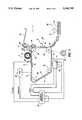
- FIG. 1is a schematic, elevational view showing an electrophotographic printing machine incorporating the features of the present invention therein;
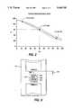
- FIG. 2is a graph showing a Tonal Reproduction Curve
- FIG. 3shows the target area interposed between adjacent images recorded on the photoconductive member
- FIG. 4is a block diagram of the adaptive controller used in the FIG. 1 printing machine.
- FIG. 1schematically depicts the various elements of an illustrative electrophotographic printing machine incorporating the adaptive control system of the present invention therein. It will become evident from the following discussion that this control system is equally well suited for use in a wide variety of printing machines and is not necessarily limited in its application to the particular embodiment depicted herein.
- the electrophotographic printing machine 1employs a belt 10 having a photoconductive surface 12 deposited on a conductive substrate 14.
- photoconductive surface 12may be made from a selenium alloy with conductive substrate 14 being made from an aluminum alloy which is electrically grounded.
- Other suitable photoconductive surfaces and conductive substratesmay also be employed.
- Belt 10moves in the direction of arrow 16 to advance successive portions of photoconductive surface 12 through the various processing stations disposed about the path of movement thereof. As shown, belt 10 is entrained about rollers 18, 20, 22, 24. Roller 24 is coupled to motor 26 which drives roller 24 so as to advance belt 10 in the direction of arrow 16. Rollers 18, 20, and 22 are idler rollers which rotate freely as belt 10 moves in the direction of arrow 16.
- a corona generating deviceindicated generally by the reference numeral 28, charges a portion of photoconductive surface 12 of belt 10 to a relatively high, substantially uniform potential.
- a Raster Input Scanner (RIS) and a Raster Output Scanner (ROS)are used to expose the charged portions of photoconductive surface 12 to record an electrostatic latent image thereon.
- the RIS(not shown), contains document illumination lamps, optics, a mechanical scanning mechanism and photosensing elements such as charged couple device (CCD) arrays.
- the RIScaptures the entire image from the original document and converts it to a series of raster scan lines. These raster scan lines are transmitted from the RIS to a ROS 36.
- ROS 36illuminates the charged portion of photoconductive surface 12 with a series of horizontal lines with each line having a specific number of pixels per inch.
- An exemplary ROS 36has lasers with rotating polygon mirror blocks, solid state modulator bars and mirrors. Still another type of exposure system would merely utilize a ROS 36 with the ROS 36 being controlled by the output from an electronic subsystem (ESS) which prepares and manages the image data flow between a computer and the ROS 36.
- ESSelectronic subsystem
- the ESS(not shown) is the control electronics for the ROS 36 and may be a self-contained, dedicated minicomputer. Thereafter, belt 10 advances the electrostatic latent image recorded on photoconductive surface 12 to development station C.
- An original documentmay be positioned face down upon a transparent platen. Lamps would flash light rays onto the original document. The light rays reflected from original document are transmitted through a lens forming a light image thereof. The lens focuses the light image onto the charged portion of photoconductive surface to selectively dissipate the charge thereon. This records an electrostatic latent image on the photoconductive surface which corresponds to the informational areas contained within the original document disposed upon the transparent platen.
- a magnetic brush developer systemtransports developer material comprising carrier granules having toner particles adhering triboelectrically thereto into contact with the electrostatic latent image recorded on photoconductive surface 12. Toner particles are attracted from the carrier granules to the latent image forming a powder image on photoconductive surface 12 of belt 10.
- sheet feeding apparatus 48includes a feed roll 50 contacting the uppermost sheet of a stack of sheets 52. Feed roll 50 rotates to advance the uppermost sheet from stack 50 into sheet chute 54. Chute 54 directs the advancing sheet of support material 46 into contact with photoconductive surface 12 of belt 10 in a timed sequence so that the toner powder image developed thereon contacts the advancing sheet of support material at transfer station D.
- Transfer station Dincludes a corona generating device 56 which sprays ions onto the backside of sheet 46. This attracts the toner powder image from photoconductive surface 12 to sheet 46. After transfer, the sheet continues to move in the direction of arrow 58 onto a conveyor 60 which moves the sheet to fusing station E.
- Fusing station Eincludes a fuser assembly, indicated generally by the reference numeral 62, which permanently affixes the powder image to sheet 46.
- fuser assembly 62includes a heated fuser roller 64 driven by a motor and a backup roller 66.
- Sheet 46passes between fuser roller 64 and backup roller 66 with the toner powder image contacting fuser roller 64. In this manner, the toner powder image is permanently affixed to sheet 46.
- chute 68guides the advancing sheet to catch tray 70 for subsequent removal from the printing machine by the operator.
- Cleaning station Fincludes a preclean corona generating device (not shown) and a rotatably mounted fibrous brush 72 in contact with photoconductive surface 12.
- the preclean corona generatorneutralizes the charge attracting the particles to the photoconductive surface. These particles are cleaned from the photoconductive surface by the rotation of brush 72 in contact therewith.
- a discharge lamp(not shown) floods photoconductive surface 12 with light to dissipate any residual charge remaining thereon prior to the charging thereof for the next successive imaging cycle.
- an adaptive controller 30that controls the tonal reproduction curve. Controller 30 adjusts compensation filters in real time to control parameter variations. Controller 30 divides the adaptive control into two tasks, parameter identification and control modification. The estimated results are used to modify the compensation parameters.
- Tonal reproduction curve controlprovides uniform gray scale development and effective translation of halftones, highlights, and shadow details, as well as mid-tone densities.
- the control stability of all the density levels on the tonal reproduction curvemake photographic reproductions and other halftone documents invariant from machine to machine and copy to copy.
- a tonal reproduction curveis shown in terms of a measure of whiteness (L*) versus the toner area coverage (Cin) of developed image fill patterns.
- L*represents the differential response of the human eye to a developed image and is used as a metric for density variation. Since L* is non-linear in terms of density, density information for values of Cin are converted to L* units by the formula:
- Densityis a developed toner mass value measured by a laboratory grade densitometer during the design phase of the printing machine.
- L* verus Cin process control targetsare defined based upon statistical experiments performed during the design phase of the printing machine. A L* to relative reflectance correlation is accomplished using experimental data to generate relative reflectance targets that correspond to given L * values.
- the relative reflectance (RR) targetsare then embedded as a lookup table in the machine software. Three process control targets are illustrated in FIG. 2.
- the targetsinclude L*-Cin values for highlight density, halftone density, and solid area density.
- the targetsare labeled (L*)12.5%, (L*)50% and (L*)87.5% respectively.
- Corresponding RR targetssuch as RR 12 .5, RR 50 , and RR 87 .5 are stored in a machine software lookup table.
- Variations in the L* values shown in FIG. 2are controlled to a standard deviation of plus or minus 2 units or 2 sigma-limits.
- the standard deviationis indicated graphically, in FIG. 2, by a space defined between two opposing dotted lines adjacent to the tonal reproduction curve.
- the standard deviation for the majority of L* corresponding to a Cin density of 50%should lie, as shown, in a range of 60 ⁇ 4, or 56 to 64 units.
- state variablessuch as charge voltage (V CHARGE ), developer bias voltage (V BIAS ), exposure intensity (EXPOSURE), and toner concentration (% TC) are used as actuators to control the tonal reproduction curve of FIG. 2.
- Changes in output generated by the adaptive controller 30are measured by a toner area coverage (TAC) sensor 32 and a toner concentration (TC) sensor 33.
- TAC sensor 32which is located after development station C, measures the developed toner mass for different area coverage patches recorded on the photoconductive surface 12.
- TC sensor 33which is located in the magnetic brush developer system 38 measures toner concentration inside the housing.
- Control algorithms for a Linear Quadratic Controller and a Parameter Identifierdiscussed hereinafter with reference to FIG. 4, process this information to continually adjust exposure, development potential, development bias, and toner concentration to maintain the process within a specified operating latitude that assures acceptable image quality.
- TC sensor 33measures the magnetic field of the developer material comprised of carrier granules (magnetic powder) and toner particles (pigment powder) mixed proportionally to create the developer housed in the developer system 38.
- Carrier granulespossess a high degree of permeability to support a magnetic flux density while toner is a lower permeability material.
- the combined permeabilitygenerates a signal which is transmitted to controller 30.
- TC Sensor 33is part of a toner concentration feedback loop using a separate Proportional/Integral (PI) controller for dispensing toner.
- the PI controlleris internal to controller 30 and will be discussed in further detail with reference to FIG. 4.
- TAC sensor 32is an infrared reflectance type densitometer that measures the density of toner particles developed on the photoconductive the surface 12.
- a composite toner test patch 110is imaged in the interdocument area of photoconductive surface 12.
- the photoconductive surface 12is illustrated as containing two documents images: image 1 and image 2.
- the test patch 110is shown in the interdocument space between image 1 and image 2 and is that portion of the photoconductive surface 12 sensed by the TAC sensor 32 to provide the necessary signals for control.
- the composite patch 110measures 15 millimeters, in the process direction, indicated by arrow 111 and 45 millimeters, in the cross process direction, indicated by arrow 113.
- Patch 110consists of a segment 114 for solid area density (87.5%), a segment 116 for halftone density (50%), and a segment 118 for highlight density (12.5%).
- the TAC sensor 32Before the TAC sensor 32 can provide a meaningful response to the relative reflectance of patch segments 114, 116, and 118, the TAC sensor 32 must be calibrated by measuring the light reflected from a bare or clean area portion 112 of photoconductive belt surface 12. For calibration purposes, current to the light emitting diode (LED) internal to the TAC sensor 32 is increased until the voltage generated by the TAC sensor 32 in response to light reflected from the bare or clean area 112 is between 3 and 5 volts.
- LEDlight emitting diode
- bit patterns for the composite patch 110are computer generated during the design stage of the machine.
- the bit patternsare downloaded to an electrical programmable read only memory (EPROM) contained in the video module (Not Shown) of the ROS 36.
- EPROMelectrical programmable read only memory
- the composite patchis imaged in the interdocument zone of photoconductive surface 12 by the ROS 36 at a rate of one patch per revolution of photoconductive surface 12.
- the video modulesends the bit pattern information to ROS 36.
- the ROS 36changes exposure intensity pixel by pixel, so that the intensity variation of the individual pixels correspondingly changes the discharge potential on the photoconductive surface 12 and forms a latent image of the segments comprising the composite patch 110.
- the latent imageis developed with toner material.
- the TAC sensor 32After development, the TAC sensor 32 detects the intensity of the light reflected from the clean area 112 of the photoconductive surface 12 and each toned area segment 114, 116, and 118 three times. The change in reflectance between the clean area 112 and each toned segment of the composite patch 110 forms a relative reflectance reading that is a measure of the developed toner mass for each segment of the composite test patch 110. Readings generated by the TAC 32 sensor are then transmitted to the adaptive controller 32.
- Differences in developabilitycause the same development voltage to result in different developed masses per unit area. Variations in developability may have a number of sources, but principle among them are triboelectric variations and developer roll to photoconductive surface spacing.
- the actuator for controlling developabilityis the peak-to-peak AC voltage on the developer roll.
- the TAC sensor 32is used to acquire an approximation of developability and then adjust the developer voltage until developability is within an acceptable standard deviation on the tonal reproduction curve shown in FIG. 2.
- the TAC sensor 32is used, as discussed with reference to FIG. 1, to measure the relative reflectance of patch segments shown in FIG. 3. Since there is a correlation between the relative reflectance of the developed toner mass for different area coverage patches recorded on the photoconductive surface, to the L* or differential response of the human eye, the TAC sensor 32 measurement is used as a surrogate for a Cin measurement. Differences between the actual toner reproduction curve and the nominal curve are then reduced by new actuator commands issued to the electrophotographic printing by the controller 30, shown in FIG. 1, to adjust exposure, charge, and developer bias.
- Cin-L* spaceOptimization of the Cin-L* space is proceeded by the first two steps of the process setup for two reasons: First, the TAC sensor 32 must be calibrated before it can be used. Second, without the developability control, Cin-L* optimization may cause the charge potential to vary widely from setup to setup in order to compensate for differences in developability.
- ARMAautoregressive moving average model
- ⁇represents the unknown parameter matrix
- ⁇represents the known input signal vector
- ⁇represents a noise vector
- the unknown parameters denoted by ⁇represent the sensitivity of L* with reference to the actuators.
- Nominal values for the unknown parameter matrix ⁇are derived during the machine design stage and embedded in the machine software.
- the L* levels derived from measurements of the composite test patchvary with changes in the actuator levels and also, with the presence of process noise.
- Process noisestems from the change in material charging characteristics which are influenced by relative humidity, temperature, and throughput of the developer material from the developer to the photoconductive surface. Another source of noise is arises from changes in the discharge characteristic of the photoconductive surface which is influenced by age, temperature, and relative humidity.
- ⁇ L* SAis an individual term of the output vector Y and is equal to the error value of the differential response of the human eye to a solid area test patch
- ⁇ L* HTis an individual term of the output vector Y and is equal to the error value of the differential response of the human eye to a halftone test patch
- ⁇ L* HLis an individual term of the output vector Y and is equal to the error value of the differential response of the human eye to a highlight test patch
- ⁇ 11(t) ⁇ 12(t), ⁇ 13(t), ⁇ 14(t), ⁇ 21(t), ⁇ 22(t), ⁇ 23(t), ⁇ 24(t), ⁇ 31(t), ⁇ 32(t), ⁇ 33(t), ⁇ 34(t),are individual terms of the unknown parameter matrix ⁇
- ⁇ V chargeis an individual term of the known input signal vector ⁇ and is equal the change in charge potential
- ⁇ V biasis an individual term of the known input signal vector ⁇ and is equal to the change in development potential
- ⁇ Exposureis an individual term of the known input signal vector ⁇ and is equal to the change in exposure intensity
- ⁇ TCis an individual term of the known input signal vector ⁇ and is equal to the change in toner concentration
- ⁇ 1, ⁇ 2, and ⁇ 3are individual terms of the noise vector ⁇ .
- the controller 30has three components, a parameter identifier 42 and a linear quadratic controller 40, and a Proportional Integral (PI) controller 103.
- the output parameters from the controller 40include charge potential (V CHARGE ), development potential (V BIAS ), exposure intensity (EXPOSURE), and a toner reference signal TC(Ref).
- V CHARGEcharge potential
- V BIASdevelopment potential
- EXPOSUREexposure intensity
- TC(Ref) controllera toner reference signal
- the signalare the inputs actuators for the electrophotographic printing machine 1 and are connected to the electrophotographic printing machine 1 by signal lines 83, 84, and 85. Signal outputs from the electrophotographic printing machine 1 are measured by the TAC sensor 32.
- the TAC 32 sensor readingsare enabled at the photoconductive belt interdocument zone, during proper intervals based upon the machine timing of electrophotographic printing machine 1. As discussed previously with reference to FIG. 3, a TAC sensor reading from a clean photoconductive surface is compared with the toned area of the composite test patch.
- the relative reflectance for each segment of the composite test patch (L*) SA , (L*) HT , and (L*) HLis computed and conveyed by output lines 91, 92, and 93 to corresponding summing points 97, 98, and 99.
- the computed relative reflectance values for (L*) SA , (L*) HT , and (L*) HLare compared to target values (L*) SA (Ref), (L*) HT (Ref), and (L*) HL (Ref) at summing points 97, 98, and 99 from which error values ⁇ L* SA , ⁇ L* HT , and ⁇ L* HL are generated.
- the error valuesare transmitted to the Linear Quadratic Controller 40 by input lines 80, 81, and 82.
- the Linear Quadratic Controller 40computes new values for the next actuator levels.
- the Linear Quadratic Controller 40minimizes the sum of the squares of the error values and also, the sum of the squares of the actuator movements with an objective factor:
- w1, w2, and w3are weights associated with respective solid area, halftone, and highlight value
- e SA , e HT , and e HLare respectively, the errors in the solid area, halftone, and highlight values read from the composite test patch.
- the sum of the squares of actuator movementsis included to dampen the excursions of the actuators and make the operation of the Linear Quadratic Controller 40 robust in the presence of noise.
- the new actuator commandsare conveyed to the electrophotographic printing machine 1 by conductors 83, 84, and 85. Corresponding adjustments are automatically made to the corona charging device, the developer bias control, and the ROS exposure level so as to match the new actuator values. The process repeats for every revolution of the photoconductive belt in order to adjust image quality to the specified targets.
- the control of toner concentrationis accomplished by a Proportional/Integral (PI) controller 103 that operates once every second of machine operation. Controller 40 generates an output toner concentration reference signal TC(Ref), on signal line 86. The TC(Ref) signal is transmitted to one input of summing point 100. Toner sensor 33 generates a % TC signal corresponding to the percentage of toner concentration contained in the development system 38 of electrophotographic printing machine 1. The output % TC signal is transmitted to a second input of summing point 100, via signal line 106. Summing point 100 determines an error value ⁇ TC which is the difference between the TC set point TC(Ref), generated by controller 40 and the toner concentration % TC, sensed by toner sensor 33. Error value ⁇ TC, is transmitted to controller PI 103, by signal line 102 where an algorithm computes the amount of toner concentration for the next toner dispenser actuation. The algorithm for dispensing toner is:
- K Pis a proportional constant stored the machine memory
- K Iis an integral constant stored in the machine memory
- eis the error value ⁇ TC determined by the summing point
- tis iteration number of e.
- the PI controller 103When TC sensor 33 generates a signal corresponding to either a low toner or high toner concentration, the PI controller 103 correspondingly actuates the toner dispenser (Not Shown) in development system 38, via signal line 104 to add toner to the developer housing of the developer system 38 to increase toner concentration or de-energize to decrease toner concentration.
- the actuator input levels corresponding to charge potential (V CHARGE ), development potential (V BIAS ), exposure intensity (EXPOSURE), and % TCare conveyed to the parameter identifier 42 via signal lines 87,88, 89, and 90.
- the output relative reflectance values for (L*) SA , (L*) HT , and (L*) HLare conveyed to the parameter identifier 42 via signal lines 94, 95, and 96.
- Parameter identifier 42computes a new set of unknown parameters for the ⁇ matrix in the ARMA perturbation model. Parameter identification is accomplished by the means of a recursive least squares technique.
- the updated parametersare sent to the Linear Quadratic Controller 40 by the way of a data bus 98, once every third revolution of the photoconductive belt, so as to upgrade the ARMA perturbation model and enable controller 40 to compute V CHARGE , V BIAS , EXPOSURE, and TC(Ref) as a function of ⁇ L* SA , ⁇ L* HT , and ⁇ L* HL , % TC.
- the apparatus of the present inventionincludes an adaptive controller for controlling a plurality of process parameters in an electrophotographic printing machine.
- a toner area coverage sensordetects a plurality of density values for a toner image and generates corresponding signals.
- a toner concentration sensordetects a level of toner concentration and generates a corresponding signal.
- a controlleris adapted to receive the signals from the toner area coverage sensor and the toner concentration sensor and generates a set of control signals indicative thereof.
- An identifieris adapted to receive the same signals generated by the sensors and modifies the control parameters of the controller.
Landscapes
- Engineering & Computer Science (AREA)
- Microelectronics & Electronic Packaging (AREA)
- Physics & Mathematics (AREA)
- General Physics & Mathematics (AREA)
- Control Or Security For Electrophotography (AREA)
Abstract
Description
L*=116(Density).sup.1/3 -16
Y(t)=θ.sup.T (t)φ(t)+ψ(t)
J=Σ(w.sub.1 e.sup.2.sub.SA +w.sub.2 e.sup.2.sub.HT +w.sub.3 e.sup.2.sub.HL)
Dispenser Action=K.sub.P ·e(t)+K.sub.I ·∫e(t)
Claims (31)
Priority Applications (3)
| Application Number | Priority Date | Filing Date | Title |
|---|---|---|---|
| US08/228,787US5436705A (en) | 1994-04-18 | 1994-04-18 | Adaptive process controller for electrophotographic printing |
| JP7089575AJPH07295310A (en) | 1994-04-18 | 1995-04-14 | Adaptive type process controller for electrophotography printing |
| BR9501597ABR9501597A (en) | 1994-04-18 | 1995-04-17 | Electrophotographic printing machine |
Applications Claiming Priority (1)
| Application Number | Priority Date | Filing Date | Title |
|---|---|---|---|
| US08/228,787US5436705A (en) | 1994-04-18 | 1994-04-18 | Adaptive process controller for electrophotographic printing |
Publications (1)
| Publication Number | Publication Date |
|---|---|
| US5436705Atrue US5436705A (en) | 1995-07-25 |
Family
ID=22858575
Family Applications (1)
| Application Number | Title | Priority Date | Filing Date |
|---|---|---|---|
| US08/228,787Expired - Fee RelatedUS5436705A (en) | 1994-04-18 | 1994-04-18 | Adaptive process controller for electrophotographic printing |
Country Status (3)
| Country | Link |
|---|---|
| US (1) | US5436705A (en) |
| JP (1) | JPH07295310A (en) |
| BR (1) | BR9501597A (en) |
Cited By (81)
| Publication number | Priority date | Publication date | Assignee | Title |
|---|---|---|---|---|
| US5581221A (en)* | 1993-12-22 | 1996-12-03 | Minolta Co. Ltd. | Electrophotographic image forming apparatus |
| US5606395A (en)* | 1996-01-11 | 1997-02-25 | Xerox Corporation | Method and apparatus for adjusting machine parameters in a printing machine to provide real-time print appearance control |
| US5631728A (en)* | 1996-01-31 | 1997-05-20 | Eastman Kodak Company | Process control for electrophotographic recording |
| US5655174A (en)* | 1996-05-22 | 1997-08-05 | Hewlett-Packard Company | System with ambient sensor for estimating printing supply consumption |
| US5666194A (en)* | 1996-05-30 | 1997-09-09 | Xerox Corporation | Apparatus for detecting marking material |
| US5678131A (en)* | 1995-08-22 | 1997-10-14 | Eastman Kodak Company | Apparatus and method for regulating toning contrast and extending developer life by long-term adjustment of toner concentration |
| US5708916A (en)* | 1996-11-26 | 1998-01-13 | Xerox Corporation | Developed mass per unit area controller without using electrostatic measurements |
| US5710958A (en)* | 1996-08-08 | 1998-01-20 | Xerox Corporation | Method for setting up an electrophotographic printing machine using a toner area coverage sensor |
| US5749021A (en)* | 1996-12-04 | 1998-05-05 | Xerox Corporation | Developed mass per unit area (DMA) controller to correct for development errors |
| US5797064A (en)* | 1997-04-09 | 1998-08-18 | Xerox Corporation | Pseudo photo induced discharged curve generator for xerographic setup |
| EP0871080A1 (en)* | 1997-04-09 | 1998-10-14 | Xerox Corporation | Background detection and compensation |
| EP0903642A1 (en)* | 1997-09-10 | 1999-03-24 | Xerox Corporation | Toner concentration control |
| US5953555A (en)* | 1998-04-15 | 1999-09-14 | Xerox Corporation | Automatic adjustment of area coverage detector position |
| US5991558A (en)* | 1997-03-27 | 1999-11-23 | Fuji Xerox Co., Ltd. | Image forming apparatus that control the reflected light detected by an optical scanner in response to a gradation area percentage of a toner patch |
| US6021288A (en)* | 1997-09-22 | 2000-02-01 | Minolta Co., Ltd. | Image forming apparatus |
| US6035152A (en)* | 1997-04-11 | 2000-03-07 | Xerox Corporation | Method for measurement of tone reproduction curve |
| US6081348A (en)* | 1998-03-05 | 2000-06-27 | Xerox Corporation | Ros beam failure detector |
| US6115561A (en)* | 1996-07-22 | 2000-09-05 | Canon Kabushiki Kaisha | Image forming apparatus and a controlling method of an image forming apparatus |
| US6118953A (en)* | 1998-09-18 | 2000-09-12 | Eastman Kodak Company | Electrostatographic apparatus and method with programmable toner concentration decline with the developer life |
| EP0763783A3 (en)* | 1995-09-13 | 2000-11-08 | Xerox Corporation | Method of development control in a printing machine |
| US6166550A (en)* | 1998-11-16 | 2000-12-26 | Xerox Corporation | Charge measuring instrument |
| US6321043B1 (en) | 2000-12-12 | 2001-11-20 | Xerox Corporation | Control of halftone and solid area image quality by way of a halftone discharge ratio |
| US6320387B1 (en) | 1998-11-16 | 2001-11-20 | Xerox Corporation | Charge measuring instrument for flexible materials |
| US6366362B1 (en) | 1998-12-23 | 2002-04-02 | Xerox Corporation | Method and apparatus for adjusting input binary image halftone dots using template matching controlled by print engine xerographic density information to maintain constant tone reproduction on printed output over time |
| US6415114B1 (en) | 1999-07-28 | 2002-07-02 | Seiko Epson Corporation | Image forming apparatus and method |
| US6505517B1 (en) | 1999-07-23 | 2003-01-14 | Rosemount Inc. | High accuracy signal processing for magnetic flowmeter |
| US6519546B1 (en) | 1996-11-07 | 2003-02-11 | Rosemount Inc. | Auto correcting temperature transmitter with resistance based sensor |
| US6532392B1 (en) | 1996-03-28 | 2003-03-11 | Rosemount Inc. | Transmitter with software for determining when to initiate diagnostics |
| US6539267B1 (en) | 1996-03-28 | 2003-03-25 | Rosemount Inc. | Device in a process system for determining statistical parameter |
| US20030086717A1 (en)* | 2001-08-11 | 2003-05-08 | Samsung Electronics Co., Ltd. | Tone reproduction curve control method |
| US6601005B1 (en) | 1996-11-07 | 2003-07-29 | Rosemount Inc. | Process device diagnostics using process variable sensor signal |
| US6611775B1 (en) | 1998-12-10 | 2003-08-26 | Rosemount Inc. | Electrode leakage diagnostics in a magnetic flow meter |
| US6615149B1 (en) | 1998-12-10 | 2003-09-02 | Rosemount Inc. | Spectral diagnostics in a magnetic flow meter |
| US6629059B2 (en) | 2001-05-14 | 2003-09-30 | Fisher-Rosemount Systems, Inc. | Hand held diagnostic and communication device with automatic bus detection |
| US6701274B1 (en) | 1999-08-27 | 2004-03-02 | Rosemount Inc. | Prediction of error magnitude in a pressure transmitter |
| US6754601B1 (en) | 1996-11-07 | 2004-06-22 | Rosemount Inc. | Diagnostics for resistive elements of process devices |
| US6772036B2 (en) | 2001-08-30 | 2004-08-03 | Fisher-Rosemount Systems, Inc. | Control system using process model |
| US20040165899A1 (en)* | 2003-02-26 | 2004-08-26 | Oki Data Corporation | Image forming apparatus |
| US20050024468A1 (en)* | 2003-05-30 | 2005-02-03 | Kyocera Mita Corporation | Exposure unit and image forming apparatus provided with the exposure unit |
| US6859755B2 (en) | 2001-05-14 | 2005-02-22 | Rosemount Inc. | Diagnostics for industrial process control and measurement systems |
| US6907383B2 (en) | 1996-03-28 | 2005-06-14 | Rosemount Inc. | Flow diagnostic system |
| US6920799B1 (en) | 2004-04-15 | 2005-07-26 | Rosemount Inc. | Magnetic flow meter with reference electrode |
| US6970003B2 (en) | 2001-03-05 | 2005-11-29 | Rosemount Inc. | Electronics board life prediction of microprocessor-based transmitters |
| US7010459B2 (en) | 1999-06-25 | 2006-03-07 | Rosemount Inc. | Process device diagnostics using process variable sensor signal |
| US7018800B2 (en) | 2003-08-07 | 2006-03-28 | Rosemount Inc. | Process device with quiescent current diagnostics |
| US7031020B1 (en)* | 1994-04-22 | 2006-04-18 | Canon Kabushiki Kaisha | Image processing method, apparatus and controller |
| US20060087706A1 (en)* | 2004-10-22 | 2006-04-27 | Samsung Electronics Co., Ltd. | Method of compensating color tone for color printer and color printer having color tone compensator |
| US7046180B2 (en) | 2004-04-21 | 2006-05-16 | Rosemount Inc. | Analog-to-digital converter with range error detection |
| US20060153582A1 (en)* | 2005-01-11 | 2006-07-13 | Xerox Corporation | Method and system for using toner concentration as an active control actuator for TRC control |
| US7085610B2 (en) | 1996-03-28 | 2006-08-01 | Fisher-Rosemount Systems, Inc. | Root cause diagnostics |
| US20070077081A1 (en)* | 2005-09-30 | 2007-04-05 | Campbell Alan S | Optimization of operating parameters, including imaging power, in an electrophotographic device |
| US7254518B2 (en) | 1996-03-28 | 2007-08-07 | Rosemount Inc. | Pressure transmitter with diagnostics |
| US7290450B2 (en) | 2003-07-18 | 2007-11-06 | Rosemount Inc. | Process diagnostics |
| US20070263238A1 (en)* | 2006-05-12 | 2007-11-15 | Xerox Corporation | Automatic image quality control of marking processes |
| US20070292148A1 (en)* | 2006-06-14 | 2007-12-20 | Eastman Kodak Company | Print quality maintenance method and system |
| US7321846B1 (en) | 2006-10-05 | 2008-01-22 | Rosemount Inc. | Two-wire process control loop diagnostics |
| US20080025738A1 (en)* | 2006-07-31 | 2008-01-31 | Samsung Electronics Co., Ltd. | Toner density estimating method and apparatus useing toner image and toner supplying method and apparatus |
| US20080082182A1 (en)* | 2006-09-29 | 2008-04-03 | Brother Kogyo Kabushiki Kaisha | Adaptive control device, image forming apparatus, and recording medium |
| US7523667B2 (en) | 2003-12-23 | 2009-04-28 | Rosemount Inc. | Diagnostics of impulse piping in an industrial process |
| US7590511B2 (en) | 2007-09-25 | 2009-09-15 | Rosemount Inc. | Field device for digital process control loop diagnostics |
| US7623932B2 (en) | 1996-03-28 | 2009-11-24 | Fisher-Rosemount Systems, Inc. | Rule set for root cause diagnostics |
| US7627441B2 (en) | 2003-09-30 | 2009-12-01 | Rosemount Inc. | Process device with vibration based diagnostics |
| US7630861B2 (en) | 1996-03-28 | 2009-12-08 | Rosemount Inc. | Dedicated process diagnostic device |
| US20100021189A1 (en)* | 2008-07-22 | 2010-01-28 | Xerox Corporation | Printer control system to minimize two-dimensional image quality defects |
| DE102008056967A1 (en)* | 2008-11-11 | 2010-05-20 | OCé PRINTING SYSTEMS GMBH | Method for regulating width of characters to be printed on print substrate by electrographic printer, involves comparing measurement signal with preset threshold signal based on which light energy transferred from generator is controlled |
| US7750642B2 (en) | 2006-09-29 | 2010-07-06 | Rosemount Inc. | Magnetic flowmeter with verification |
| US7921734B2 (en) | 2009-05-12 | 2011-04-12 | Rosemount Inc. | System to detect poor process ground connections |
| US7940189B2 (en) | 2005-09-29 | 2011-05-10 | Rosemount Inc. | Leak detector for process valve |
| US7949495B2 (en) | 1996-03-28 | 2011-05-24 | Rosemount, Inc. | Process variable transmitter with diagnostics |
| US7953501B2 (en) | 2006-09-25 | 2011-05-31 | Fisher-Rosemount Systems, Inc. | Industrial process control loop monitor |
| US8112565B2 (en) | 2005-06-08 | 2012-02-07 | Fisher-Rosemount Systems, Inc. | Multi-protocol field device interface with automatic bus detection |
| US8290721B2 (en) | 1996-03-28 | 2012-10-16 | Rosemount Inc. | Flow measurement diagnostics |
| US8594518B2 (en) | 2011-05-16 | 2013-11-26 | Xerox Corporation | Diagnostic method for determining imager contribution to printing defects |
| US8788070B2 (en) | 2006-09-26 | 2014-07-22 | Rosemount Inc. | Automatic field device service adviser |
| US8898036B2 (en) | 2007-08-06 | 2014-11-25 | Rosemount Inc. | Process variable transmitter with acceleration sensor |
| US9052240B2 (en) | 2012-06-29 | 2015-06-09 | Rosemount Inc. | Industrial process temperature transmitter with sensor stress diagnostics |
| US9207670B2 (en) | 2011-03-21 | 2015-12-08 | Rosemount Inc. | Degrading sensor detection implemented within a transmitter |
| US20160282796A1 (en)* | 2015-03-26 | 2016-09-29 | Konica Minolta, Inc. | Sheet processor and image forming system |
| US9602122B2 (en) | 2012-09-28 | 2017-03-21 | Rosemount Inc. | Process variable measurement noise diagnostic |
| US10241457B1 (en) | 2018-01-19 | 2019-03-26 | Eastman Kodak Company | Process control sensing of toner coverage |
| CN116160760A (en)* | 2023-01-16 | 2023-05-26 | 广州大学 | LQR color registration control method of electronic shaft gravure press based on dimension reduction observer |
Families Citing this family (3)
| Publication number | Priority date | Publication date | Assignee | Title |
|---|---|---|---|---|
| JP3446727B2 (en)* | 1999-09-06 | 2003-09-16 | セイコーエプソン株式会社 | Image forming apparatus and image forming method |
| KR100423480B1 (en)* | 2001-11-20 | 2004-03-18 | 삼성전자주식회사 | Printer having plural toner density sensor and a supply of toner control method thereof |
| KR100630953B1 (en) | 2005-09-06 | 2006-10-04 | 삼성전자주식회사 | Image forming apparatus having adjustment function of toner supply amount |
Citations (4)
| Publication number | Priority date | Publication date | Assignee | Title |
|---|---|---|---|---|
| US4348099A (en)* | 1980-04-07 | 1982-09-07 | Xerox Corporation | Closed loop control of reproduction machine |
| US4553033A (en)* | 1983-08-24 | 1985-11-12 | Xerox Corporation | Infrared reflectance densitometer |
| US4965634A (en)* | 1988-11-18 | 1990-10-23 | Ricoh Company, Ltd. | Image recording apparatus capable of controlling image density |
| US5200783A (en)* | 1990-08-30 | 1993-04-06 | Sharp Kabushiki Kaisha | Black image density correcting device |
- 1994
- 1994-04-18USUS08/228,787patent/US5436705A/ennot_activeExpired - Fee Related
- 1995
- 1995-04-14JPJP7089575Apatent/JPH07295310A/ennot_activeWithdrawn
- 1995-04-17BRBR9501597Apatent/BR9501597A/ennot_activeApplication Discontinuation
Patent Citations (4)
| Publication number | Priority date | Publication date | Assignee | Title |
|---|---|---|---|---|
| US4348099A (en)* | 1980-04-07 | 1982-09-07 | Xerox Corporation | Closed loop control of reproduction machine |
| US4553033A (en)* | 1983-08-24 | 1985-11-12 | Xerox Corporation | Infrared reflectance densitometer |
| US4965634A (en)* | 1988-11-18 | 1990-10-23 | Ricoh Company, Ltd. | Image recording apparatus capable of controlling image density |
| US5200783A (en)* | 1990-08-30 | 1993-04-06 | Sharp Kabushiki Kaisha | Black image density correcting device |
Cited By (96)
| Publication number | Priority date | Publication date | Assignee | Title |
|---|---|---|---|---|
| US5581221A (en)* | 1993-12-22 | 1996-12-03 | Minolta Co. Ltd. | Electrophotographic image forming apparatus |
| US7031020B1 (en)* | 1994-04-22 | 2006-04-18 | Canon Kabushiki Kaisha | Image processing method, apparatus and controller |
| US5678131A (en)* | 1995-08-22 | 1997-10-14 | Eastman Kodak Company | Apparatus and method for regulating toning contrast and extending developer life by long-term adjustment of toner concentration |
| EP0763783A3 (en)* | 1995-09-13 | 2000-11-08 | Xerox Corporation | Method of development control in a printing machine |
| US5606395A (en)* | 1996-01-11 | 1997-02-25 | Xerox Corporation | Method and apparatus for adjusting machine parameters in a printing machine to provide real-time print appearance control |
| US5631728A (en)* | 1996-01-31 | 1997-05-20 | Eastman Kodak Company | Process control for electrophotographic recording |
| US6539267B1 (en) | 1996-03-28 | 2003-03-25 | Rosemount Inc. | Device in a process system for determining statistical parameter |
| US7630861B2 (en) | 1996-03-28 | 2009-12-08 | Rosemount Inc. | Dedicated process diagnostic device |
| US8290721B2 (en) | 1996-03-28 | 2012-10-16 | Rosemount Inc. | Flow measurement diagnostics |
| US6907383B2 (en) | 1996-03-28 | 2005-06-14 | Rosemount Inc. | Flow diagnostic system |
| US7085610B2 (en) | 1996-03-28 | 2006-08-01 | Fisher-Rosemount Systems, Inc. | Root cause diagnostics |
| US7254518B2 (en) | 1996-03-28 | 2007-08-07 | Rosemount Inc. | Pressure transmitter with diagnostics |
| US6532392B1 (en) | 1996-03-28 | 2003-03-11 | Rosemount Inc. | Transmitter with software for determining when to initiate diagnostics |
| US7623932B2 (en) | 1996-03-28 | 2009-11-24 | Fisher-Rosemount Systems, Inc. | Rule set for root cause diagnostics |
| US7949495B2 (en) | 1996-03-28 | 2011-05-24 | Rosemount, Inc. | Process variable transmitter with diagnostics |
| US5655174A (en)* | 1996-05-22 | 1997-08-05 | Hewlett-Packard Company | System with ambient sensor for estimating printing supply consumption |
| US5666194A (en)* | 1996-05-30 | 1997-09-09 | Xerox Corporation | Apparatus for detecting marking material |
| US6115561A (en)* | 1996-07-22 | 2000-09-05 | Canon Kabushiki Kaisha | Image forming apparatus and a controlling method of an image forming apparatus |
| US5710958A (en)* | 1996-08-08 | 1998-01-20 | Xerox Corporation | Method for setting up an electrophotographic printing machine using a toner area coverage sensor |
| US6754601B1 (en) | 1996-11-07 | 2004-06-22 | Rosemount Inc. | Diagnostics for resistive elements of process devices |
| US6601005B1 (en) | 1996-11-07 | 2003-07-29 | Rosemount Inc. | Process device diagnostics using process variable sensor signal |
| US6519546B1 (en) | 1996-11-07 | 2003-02-11 | Rosemount Inc. | Auto correcting temperature transmitter with resistance based sensor |
| US5708916A (en)* | 1996-11-26 | 1998-01-13 | Xerox Corporation | Developed mass per unit area controller without using electrostatic measurements |
| US5749021A (en)* | 1996-12-04 | 1998-05-05 | Xerox Corporation | Developed mass per unit area (DMA) controller to correct for development errors |
| US5991558A (en)* | 1997-03-27 | 1999-11-23 | Fuji Xerox Co., Ltd. | Image forming apparatus that control the reflected light detected by an optical scanner in response to a gradation area percentage of a toner patch |
| EP0871080A1 (en)* | 1997-04-09 | 1998-10-14 | Xerox Corporation | Background detection and compensation |
| US5797064A (en)* | 1997-04-09 | 1998-08-18 | Xerox Corporation | Pseudo photo induced discharged curve generator for xerographic setup |
| EP0871324A3 (en)* | 1997-04-09 | 1999-08-25 | Xerox Corporation | Photo induced discharge for xerography |
| US6035152A (en)* | 1997-04-11 | 2000-03-07 | Xerox Corporation | Method for measurement of tone reproduction curve |
| EP0903642A1 (en)* | 1997-09-10 | 1999-03-24 | Xerox Corporation | Toner concentration control |
| US5937227A (en)* | 1997-09-10 | 1999-08-10 | Xerox Corporation | Uncoupled toner concentration and tribo control |
| US6021288A (en)* | 1997-09-22 | 2000-02-01 | Minolta Co., Ltd. | Image forming apparatus |
| US6081348A (en)* | 1998-03-05 | 2000-06-27 | Xerox Corporation | Ros beam failure detector |
| US5953555A (en)* | 1998-04-15 | 1999-09-14 | Xerox Corporation | Automatic adjustment of area coverage detector position |
| US6118953A (en)* | 1998-09-18 | 2000-09-12 | Eastman Kodak Company | Electrostatographic apparatus and method with programmable toner concentration decline with the developer life |
| US6594603B1 (en) | 1998-10-19 | 2003-07-15 | Rosemount Inc. | Resistive element diagnostics for process devices |
| US6166550A (en)* | 1998-11-16 | 2000-12-26 | Xerox Corporation | Charge measuring instrument |
| US6320387B1 (en) | 1998-11-16 | 2001-11-20 | Xerox Corporation | Charge measuring instrument for flexible materials |
| US6615149B1 (en) | 1998-12-10 | 2003-09-02 | Rosemount Inc. | Spectral diagnostics in a magnetic flow meter |
| US6611775B1 (en) | 1998-12-10 | 2003-08-26 | Rosemount Inc. | Electrode leakage diagnostics in a magnetic flow meter |
| US6366362B1 (en) | 1998-12-23 | 2002-04-02 | Xerox Corporation | Method and apparatus for adjusting input binary image halftone dots using template matching controlled by print engine xerographic density information to maintain constant tone reproduction on printed output over time |
| US7010459B2 (en) | 1999-06-25 | 2006-03-07 | Rosemount Inc. | Process device diagnostics using process variable sensor signal |
| US6505517B1 (en) | 1999-07-23 | 2003-01-14 | Rosemount Inc. | High accuracy signal processing for magnetic flowmeter |
| US6415114B1 (en) | 1999-07-28 | 2002-07-02 | Seiko Epson Corporation | Image forming apparatus and method |
| US6701274B1 (en) | 1999-08-27 | 2004-03-02 | Rosemount Inc. | Prediction of error magnitude in a pressure transmitter |
| US6321043B1 (en) | 2000-12-12 | 2001-11-20 | Xerox Corporation | Control of halftone and solid area image quality by way of a halftone discharge ratio |
| US6970003B2 (en) | 2001-03-05 | 2005-11-29 | Rosemount Inc. | Electronics board life prediction of microprocessor-based transmitters |
| US6859755B2 (en) | 2001-05-14 | 2005-02-22 | Rosemount Inc. | Diagnostics for industrial process control and measurement systems |
| US6629059B2 (en) | 2001-05-14 | 2003-09-30 | Fisher-Rosemount Systems, Inc. | Hand held diagnostic and communication device with automatic bus detection |
| US20030086717A1 (en)* | 2001-08-11 | 2003-05-08 | Samsung Electronics Co., Ltd. | Tone reproduction curve control method |
| US6741816B2 (en)* | 2001-08-11 | 2004-05-25 | Samsung Electronics Co., Ltd. | Tone reproduction curve control method |
| US6772036B2 (en) | 2001-08-30 | 2004-08-03 | Fisher-Rosemount Systems, Inc. | Control system using process model |
| US7200346B2 (en)* | 2003-02-26 | 2007-04-03 | Oki Data Corporation | Image forming apparatus having different dots per unit area densities |
| US20040165899A1 (en)* | 2003-02-26 | 2004-08-26 | Oki Data Corporation | Image forming apparatus |
| US20050024468A1 (en)* | 2003-05-30 | 2005-02-03 | Kyocera Mita Corporation | Exposure unit and image forming apparatus provided with the exposure unit |
| US7290450B2 (en) | 2003-07-18 | 2007-11-06 | Rosemount Inc. | Process diagnostics |
| US7018800B2 (en) | 2003-08-07 | 2006-03-28 | Rosemount Inc. | Process device with quiescent current diagnostics |
| US7627441B2 (en) | 2003-09-30 | 2009-12-01 | Rosemount Inc. | Process device with vibration based diagnostics |
| US7523667B2 (en) | 2003-12-23 | 2009-04-28 | Rosemount Inc. | Diagnostics of impulse piping in an industrial process |
| US6920799B1 (en) | 2004-04-15 | 2005-07-26 | Rosemount Inc. | Magnetic flow meter with reference electrode |
| US7046180B2 (en) | 2004-04-21 | 2006-05-16 | Rosemount Inc. | Analog-to-digital converter with range error detection |
| US20060087706A1 (en)* | 2004-10-22 | 2006-04-27 | Samsung Electronics Co., Ltd. | Method of compensating color tone for color printer and color printer having color tone compensator |
| US20060153582A1 (en)* | 2005-01-11 | 2006-07-13 | Xerox Corporation | Method and system for using toner concentration as an active control actuator for TRC control |
| US7158732B2 (en)* | 2005-01-11 | 2007-01-02 | Xerox Corporation | Method and system for using toner concentration as an active control actuator for TRC control |
| US8112565B2 (en) | 2005-06-08 | 2012-02-07 | Fisher-Rosemount Systems, Inc. | Multi-protocol field device interface with automatic bus detection |
| US7940189B2 (en) | 2005-09-29 | 2011-05-10 | Rosemount Inc. | Leak detector for process valve |
| US20070077081A1 (en)* | 2005-09-30 | 2007-04-05 | Campbell Alan S | Optimization of operating parameters, including imaging power, in an electrophotographic device |
| US7379682B2 (en)* | 2005-09-30 | 2008-05-27 | Lexmark International, Inc. | Optimization of operating parameters, including imaging power, in an electrophotographic device |
| US20070263238A1 (en)* | 2006-05-12 | 2007-11-15 | Xerox Corporation | Automatic image quality control of marking processes |
| US7800777B2 (en)* | 2006-05-12 | 2010-09-21 | Xerox Corporation | Automatic image quality control of marking processes |
| US7539427B2 (en)* | 2006-06-14 | 2009-05-26 | Eastman Kodak Company | Print quality maintenance method and system |
| US20070292148A1 (en)* | 2006-06-14 | 2007-12-20 | Eastman Kodak Company | Print quality maintenance method and system |
| CN101118402B (en)* | 2006-07-31 | 2011-12-14 | 三星电子株式会社 | Toner density estimation method,toner density estimation method device, toner supplyment method and toner supplyment device |
| EP1887437A1 (en)* | 2006-07-31 | 2008-02-13 | Samsung Electronics Co., Ltd. | Toner density estimation |
| US7711277B2 (en) | 2006-07-31 | 2010-05-04 | Samsung Electronics Co., Ltd. | Toner density estimating method and apparatus using toner image and toner supplying method and apparatus |
| US20080025738A1 (en)* | 2006-07-31 | 2008-01-31 | Samsung Electronics Co., Ltd. | Toner density estimating method and apparatus useing toner image and toner supplying method and apparatus |
| US7953501B2 (en) | 2006-09-25 | 2011-05-31 | Fisher-Rosemount Systems, Inc. | Industrial process control loop monitor |
| US8788070B2 (en) | 2006-09-26 | 2014-07-22 | Rosemount Inc. | Automatic field device service adviser |
| US7750642B2 (en) | 2006-09-29 | 2010-07-06 | Rosemount Inc. | Magnetic flowmeter with verification |
| US7603187B2 (en)* | 2006-09-29 | 2009-10-13 | Brother Kogyo Kabushiki Kaisha | Adapative control device, image forming apparatus, and recording medium |
| US20080082182A1 (en)* | 2006-09-29 | 2008-04-03 | Brother Kogyo Kabushiki Kaisha | Adaptive control device, image forming apparatus, and recording medium |
| US7321846B1 (en) | 2006-10-05 | 2008-01-22 | Rosemount Inc. | Two-wire process control loop diagnostics |
| US8898036B2 (en) | 2007-08-06 | 2014-11-25 | Rosemount Inc. | Process variable transmitter with acceleration sensor |
| US7590511B2 (en) | 2007-09-25 | 2009-09-15 | Rosemount Inc. | Field device for digital process control loop diagnostics |
| US8331816B2 (en)* | 2008-07-22 | 2012-12-11 | Xerox Corporation | Printer control system to minimize two-dimensional image quality defects |
| US20100021189A1 (en)* | 2008-07-22 | 2010-01-28 | Xerox Corporation | Printer control system to minimize two-dimensional image quality defects |
| DE102008056967A1 (en)* | 2008-11-11 | 2010-05-20 | OCé PRINTING SYSTEMS GMBH | Method for regulating width of characters to be printed on print substrate by electrographic printer, involves comparing measurement signal with preset threshold signal based on which light energy transferred from generator is controlled |
| US7921734B2 (en) | 2009-05-12 | 2011-04-12 | Rosemount Inc. | System to detect poor process ground connections |
| US9207670B2 (en) | 2011-03-21 | 2015-12-08 | Rosemount Inc. | Degrading sensor detection implemented within a transmitter |
| US8594518B2 (en) | 2011-05-16 | 2013-11-26 | Xerox Corporation | Diagnostic method for determining imager contribution to printing defects |
| US9052240B2 (en) | 2012-06-29 | 2015-06-09 | Rosemount Inc. | Industrial process temperature transmitter with sensor stress diagnostics |
| US9602122B2 (en) | 2012-09-28 | 2017-03-21 | Rosemount Inc. | Process variable measurement noise diagnostic |
| US20160282796A1 (en)* | 2015-03-26 | 2016-09-29 | Konica Minolta, Inc. | Sheet processor and image forming system |
| US10241457B1 (en) | 2018-01-19 | 2019-03-26 | Eastman Kodak Company | Process control sensing of toner coverage |
| WO2019143493A1 (en) | 2018-01-19 | 2019-07-25 | Eastman Kodak Company | Improved process control sensing of toner coverage |
| CN116160760A (en)* | 2023-01-16 | 2023-05-26 | 广州大学 | LQR color registration control method of electronic shaft gravure press based on dimension reduction observer |
Also Published As
| Publication number | Publication date |
|---|---|
| JPH07295310A (en) | 1995-11-10 |
| BR9501597A (en) | 1995-11-14 |
Similar Documents
| Publication | Publication Date | Title |
|---|---|---|
| US5436705A (en) | Adaptive process controller for electrophotographic printing | |
| US5710958A (en) | Method for setting up an electrophotographic printing machine using a toner area coverage sensor | |
| US5887221A (en) | Signature sensing for optimum toner control with donor roll | |
| US5774761A (en) | Machine set up procedure using multivariate modeling and multiobjective optimization | |
| US5749021A (en) | Developed mass per unit area (DMA) controller to correct for development errors | |
| US5410388A (en) | Automatic compensation for toner concentration drift due to developer aging | |
| US5717978A (en) | Method to model a xerographic system | |
| US5708916A (en) | Developed mass per unit area controller without using electrostatic measurements | |
| US5749019A (en) | Look up table to control non-linear xerographic process | |
| US5243383A (en) | Image forming apparatus with predictive electrostatic process control system | |
| US5950040A (en) | Feedback control system for controlling developability of a xerographic imaging device | |
| CA2076765C (en) | Esv readings of toner test patches for adjusting ird readings of developed test patches | |
| EP1439431B1 (en) | Toner concentration sensor calibration for image forming apparatus using two-component developer | |
| JPS63244083A (en) | Electrophotographic type copying machine and colored particle discharge controller thereof | |
| EP0871324B1 (en) | Photo induced discharge for xerography | |
| EP0903642B1 (en) | Toner concentration control | |
| US6006047A (en) | Apparatus for monitoring and controlling electrical parameters of an imaging surface | |
| US5212522A (en) | Basic developability control in single component development system | |
| US5521677A (en) | Method for solid area process control for scavengeless development in a xerographic apparatus | |
| JP4511000B2 (en) | Method for performing process control for recovery processing-free development in an electrophotographic printer and apparatus provided with such process control | |
| EP1107070B1 (en) | Method and apparatus for adaptive black solid area estimation in a xerographic apparatus | |
| US7127187B2 (en) | Tone reproduction curve and developed mass per unit area control method and system | |
| US7158732B2 (en) | Method and system for using toner concentration as an active control actuator for TRC control | |
| US7274887B2 (en) | System and method for setup of toner concentration target for a toner concentration sensor | |
| EP0871080B1 (en) | Background detection and compensation |
Legal Events
| Date | Code | Title | Description |
|---|---|---|---|
| AS | Assignment | Owner name:XEROX CORPORATION, CONNECTICUT Free format text:ASSIGNMENT OF ASSIGNORS INTEREST;ASSIGNOR:RAJ, GURU B.;REEL/FRAME:006964/0963 Effective date:19940412 | |
| FPAY | Fee payment | Year of fee payment:4 | |
| AS | Assignment | Owner name:BANK ONE, NA, AS ADMINISTRATIVE AGENT, ILLINOIS Free format text:SECURITY INTEREST;ASSIGNOR:XEROX CORPORATION;REEL/FRAME:013153/0001 Effective date:20020621 | |
| FPAY | Fee payment | Year of fee payment:8 | |
| AS | Assignment | Owner name:JPMORGAN CHASE BANK, AS COLLATERAL AGENT, TEXAS Free format text:SECURITY AGREEMENT;ASSIGNOR:XEROX CORPORATION;REEL/FRAME:015134/0476 Effective date:20030625 Owner name:JPMORGAN CHASE BANK, AS COLLATERAL AGENT,TEXAS Free format text:SECURITY AGREEMENT;ASSIGNOR:XEROX CORPORATION;REEL/FRAME:015134/0476 Effective date:20030625 | |
| REMI | Maintenance fee reminder mailed | ||
| LAPS | Lapse for failure to pay maintenance fees | ||
| STCH | Information on status: patent discontinuation | Free format text:PATENT EXPIRED DUE TO NONPAYMENT OF MAINTENANCE FEES UNDER 37 CFR 1.362 | |
| FP | Lapsed due to failure to pay maintenance fee | Effective date:20070725 | |
| AS | Assignment | Owner name:XEROX CORPORATION, NEW YORK Free format text:RELEASE BY SECURED PARTY;ASSIGNOR:BANK ONE, NA;REEL/FRAME:033975/0830 Effective date:20030625 | |
| AS | Assignment | Owner name:XEROX CORPORATION, CONNECTICUT Free format text:RELEASE BY SECURED PARTY;ASSIGNOR:JPMORGAN CHASE BANK, N.A. AS SUCCESSOR-IN-INTEREST ADMINISTRATIVE AGENT AND COLLATERAL AGENT TO JPMORGAN CHASE BANK;REEL/FRAME:066728/0193 Effective date:20220822 |