US5436210A - Method and apparatus for injection of a liquid waste into a molten bath - Google Patents
Method and apparatus for injection of a liquid waste into a molten bathDownload PDFInfo
- Publication number
- US5436210A US5436210AUS08/013,756US1375693AUS5436210AUS 5436210 AUS5436210 AUS 5436210AUS 1375693 AUS1375693 AUS 1375693AUS 5436210 AUS5436210 AUS 5436210A
- Authority
- US
- United States
- Prior art keywords
- liquid
- gas
- conduit
- molten metal
- metal bath
- Prior art date
- Legal status (The legal status is an assumption and is not a legal conclusion. Google has not performed a legal analysis and makes no representation as to the accuracy of the status listed.)
- Expired - Lifetime
Links
Images


Classifications
- B—PERFORMING OPERATIONS; TRANSPORTING
- B01—PHYSICAL OR CHEMICAL PROCESSES OR APPARATUS IN GENERAL
- B01J—CHEMICAL OR PHYSICAL PROCESSES, e.g. CATALYSIS OR COLLOID CHEMISTRY; THEIR RELEVANT APPARATUS
- B01J4/00—Feed or outlet devices; Feed or outlet control devices
- B01J4/001—Feed or outlet devices as such, e.g. feeding tubes
- B01J4/002—Nozzle-type elements
- B—PERFORMING OPERATIONS; TRANSPORTING
- B01—PHYSICAL OR CHEMICAL PROCESSES OR APPARATUS IN GENERAL
- B01J—CHEMICAL OR PHYSICAL PROCESSES, e.g. CATALYSIS OR COLLOID CHEMISTRY; THEIR RELEVANT APPARATUS
- B01J10/00—Chemical processes in general for reacting liquid with gaseous media other than in the presence of solid particles, or apparatus specially adapted therefor
- B01J10/005—Chemical processes in general for reacting liquid with gaseous media other than in the presence of solid particles, or apparatus specially adapted therefor carried out at high temperatures in the presence of a molten material
- F—MECHANICAL ENGINEERING; LIGHTING; HEATING; WEAPONS; BLASTING
- F27—FURNACES; KILNS; OVENS; RETORTS
- F27B—FURNACES, KILNS, OVENS OR RETORTS IN GENERAL; OPEN SINTERING OR LIKE APPARATUS
- F27B3/00—Hearth-type furnaces, e.g. of reverberatory type; Electric arc furnaces ; Tank furnaces
- F—MECHANICAL ENGINEERING; LIGHTING; HEATING; WEAPONS; BLASTING
- F27—FURNACES; KILNS; OVENS; RETORTS
- F27B—FURNACES, KILNS, OVENS OR RETORTS IN GENERAL; OPEN SINTERING OR LIKE APPARATUS
- F27B3/00—Hearth-type furnaces, e.g. of reverberatory type; Electric arc furnaces ; Tank furnaces
- F27B3/10—Details, accessories or equipment, e.g. dust-collectors, specially adapted for hearth-type furnaces
- F27B3/22—Arrangements of air or gas supply devices
- F27B3/225—Oxygen blowing
- F—MECHANICAL ENGINEERING; LIGHTING; HEATING; WEAPONS; BLASTING
- F27—FURNACES; KILNS; OVENS; RETORTS
- F27D—DETAILS OR ACCESSORIES OF FURNACES, KILNS, OVENS OR RETORTS, IN SO FAR AS THEY ARE OF KINDS OCCURRING IN MORE THAN ONE KIND OF FURNACE
- F27D3/00—Charging; Discharging; Manipulation of charge
- F27D3/16—Introducing a fluid jet or current into the charge
- F—MECHANICAL ENGINEERING; LIGHTING; HEATING; WEAPONS; BLASTING
- F27—FURNACES; KILNS; OVENS; RETORTS
- F27D—DETAILS OR ACCESSORIES OF FURNACES, KILNS, OVENS OR RETORTS, IN SO FAR AS THEY ARE OF KINDS OCCURRING IN MORE THAN ONE KIND OF FURNACE
- F27D3/00—Charging; Discharging; Manipulation of charge
- F27D3/18—Charging particulate material using a fluid carrier
- A—HUMAN NECESSITIES
- A62—LIFE-SAVING; FIRE-FIGHTING
- A62D—CHEMICAL MEANS FOR EXTINGUISHING FIRES OR FOR COMBATING OR PROTECTING AGAINST HARMFUL CHEMICAL AGENTS; CHEMICAL MATERIALS FOR USE IN BREATHING APPARATUS
- A62D2203/00—Aspects of processes for making harmful chemical substances harmless, or less harmful, by effecting chemical change in the substances
- A62D2203/10—Apparatus specially adapted for treating harmful chemical agents; Details thereof
- F—MECHANICAL ENGINEERING; LIGHTING; HEATING; WEAPONS; BLASTING
- F27—FURNACES; KILNS; OVENS; RETORTS
- F27B—FURNACES, KILNS, OVENS OR RETORTS IN GENERAL; OPEN SINTERING OR LIKE APPARATUS
- F27B3/00—Hearth-type furnaces, e.g. of reverberatory type; Electric arc furnaces ; Tank furnaces
- F27B3/08—Hearth-type furnaces, e.g. of reverberatory type; Electric arc furnaces ; Tank furnaces heated electrically, with or without any other source of heat
- F27B3/085—Arc furnaces
- F—MECHANICAL ENGINEERING; LIGHTING; HEATING; WEAPONS; BLASTING
- F27—FURNACES; KILNS; OVENS; RETORTS
- F27B—FURNACES, KILNS, OVENS OR RETORTS IN GENERAL; OPEN SINTERING OR LIKE APPARATUS
- F27B3/00—Hearth-type furnaces, e.g. of reverberatory type; Electric arc furnaces ; Tank furnaces
- F27B3/10—Details, accessories or equipment, e.g. dust-collectors, specially adapted for hearth-type furnaces
- F27B3/20—Arrangements of heating devices
- F—MECHANICAL ENGINEERING; LIGHTING; HEATING; WEAPONS; BLASTING
- F27—FURNACES; KILNS; OVENS; RETORTS
- F27D—DETAILS OR ACCESSORIES OF FURNACES, KILNS, OVENS OR RETORTS, IN SO FAR AS THEY ARE OF KINDS OCCURRING IN MORE THAN ONE KIND OF FURNACE
- F27D17/00—Arrangements for using waste heat; Arrangements for using, or disposing of, waste gases
- F27D17/10—Arrangements for using waste heat
- F—MECHANICAL ENGINEERING; LIGHTING; HEATING; WEAPONS; BLASTING
- F27—FURNACES; KILNS; OVENS; RETORTS
- F27D—DETAILS OR ACCESSORIES OF FURNACES, KILNS, OVENS OR RETORTS, IN SO FAR AS THEY ARE OF KINDS OCCURRING IN MORE THAN ONE KIND OF FURNACE
- F27D17/00—Arrangements for using waste heat; Arrangements for using, or disposing of, waste gases
- F27D17/20—Arrangements for treatment or cleaning of waste gases
- F—MECHANICAL ENGINEERING; LIGHTING; HEATING; WEAPONS; BLASTING
- F27—FURNACES; KILNS; OVENS; RETORTS
- F27D—DETAILS OR ACCESSORIES OF FURNACES, KILNS, OVENS OR RETORTS, IN SO FAR AS THEY ARE OF KINDS OCCURRING IN MORE THAN ONE KIND OF FURNACE
- F27D17/00—Arrangements for using waste heat; Arrangements for using, or disposing of, waste gases
- F27D17/30—Arrangements for extraction or collection of waste gases; Hoods therefor
- F—MECHANICAL ENGINEERING; LIGHTING; HEATING; WEAPONS; BLASTING
- F27—FURNACES; KILNS; OVENS; RETORTS
- F27D—DETAILS OR ACCESSORIES OF FURNACES, KILNS, OVENS OR RETORTS, IN SO FAR AS THEY ARE OF KINDS OCCURRING IN MORE THAN ONE KIND OF FURNACE
- F27D3/00—Charging; Discharging; Manipulation of charge
- F27D3/16—Introducing a fluid jet or current into the charge
- F27D2003/162—Introducing a fluid jet or current into the charge the fluid being an oxidant or a fuel
- F27D2003/163—Introducing a fluid jet or current into the charge the fluid being an oxidant or a fuel the fluid being an oxidant
- F27D2003/164—Oxygen
- F—MECHANICAL ENGINEERING; LIGHTING; HEATING; WEAPONS; BLASTING
- F27—FURNACES; KILNS; OVENS; RETORTS
- F27D—DETAILS OR ACCESSORIES OF FURNACES, KILNS, OVENS OR RETORTS, IN SO FAR AS THEY ARE OF KINDS OCCURRING IN MORE THAN ONE KIND OF FURNACE
- F27D3/00—Charging; Discharging; Manipulation of charge
- F27D3/16—Introducing a fluid jet or current into the charge
- F27D2003/166—Introducing a fluid jet or current into the charge the fluid being a treatment gas
- F—MECHANICAL ENGINEERING; LIGHTING; HEATING; WEAPONS; BLASTING
- F27—FURNACES; KILNS; OVENS; RETORTS
- F27D—DETAILS OR ACCESSORIES OF FURNACES, KILNS, OVENS OR RETORTS, IN SO FAR AS THEY ARE OF KINDS OCCURRING IN MORE THAN ONE KIND OF FURNACE
- F27D99/00—Subject matter not provided for in other groups of this subclass
- F27D99/0001—Heating elements or systems
- F27D99/0033—Heating elements or systems using burners
- F27D2099/0051—Burning waste as a fuel
- F—MECHANICAL ENGINEERING; LIGHTING; HEATING; WEAPONS; BLASTING
- F27—FURNACES; KILNS; OVENS; RETORTS
- F27D—DETAILS OR ACCESSORIES OF FURNACES, KILNS, OVENS OR RETORTS, IN SO FAR AS THEY ARE OF KINDS OCCURRING IN MORE THAN ONE KIND OF FURNACE
- F27D3/00—Charging; Discharging; Manipulation of charge
- F27D3/15—Tapping equipment; Equipment for removing or retaining slag
- F27D3/1509—Tapping equipment
- F27D3/1518—Tapholes
- F—MECHANICAL ENGINEERING; LIGHTING; HEATING; WEAPONS; BLASTING
- F27—FURNACES; KILNS; OVENS; RETORTS
- F27M—INDEXING SCHEME RELATING TO ASPECTS OF THE CHARGES OR FURNACES, KILNS, OVENS OR RETORTS
- F27M2001/00—Composition, conformation or state of the charge
- F27M2001/02—Charges containing ferrous elements
- F—MECHANICAL ENGINEERING; LIGHTING; HEATING; WEAPONS; BLASTING
- F27—FURNACES; KILNS; OVENS; RETORTS
- F27M—INDEXING SCHEME RELATING TO ASPECTS OF THE CHARGES OR FURNACES, KILNS, OVENS OR RETORTS
- F27M2001/00—Composition, conformation or state of the charge
- F27M2001/05—Waste materials, refuse
- Y—GENERAL TAGGING OF NEW TECHNOLOGICAL DEVELOPMENTS; GENERAL TAGGING OF CROSS-SECTIONAL TECHNOLOGIES SPANNING OVER SEVERAL SECTIONS OF THE IPC; TECHNICAL SUBJECTS COVERED BY FORMER USPC CROSS-REFERENCE ART COLLECTIONS [XRACs] AND DIGESTS
- Y10—TECHNICAL SUBJECTS COVERED BY FORMER USPC
- Y10S—TECHNICAL SUBJECTS COVERED BY FORMER USPC CROSS-REFERENCE ART COLLECTIONS [XRACs] AND DIGESTS
- Y10S423/00—Chemistry of inorganic compounds
- Y10S423/09—Reaction techniques
- Y10S423/12—Molten media
- Y—GENERAL TAGGING OF NEW TECHNOLOGICAL DEVELOPMENTS; GENERAL TAGGING OF CROSS-SECTIONAL TECHNOLOGIES SPANNING OVER SEVERAL SECTIONS OF THE IPC; TECHNICAL SUBJECTS COVERED BY FORMER USPC CROSS-REFERENCE ART COLLECTIONS [XRACs] AND DIGESTS
- Y10—TECHNICAL SUBJECTS COVERED BY FORMER USPC
- Y10S—TECHNICAL SUBJECTS COVERED BY FORMER USPC CROSS-REFERENCE ART COLLECTIONS [XRACs] AND DIGESTS
- Y10S588/00—Hazardous or toxic waste destruction or containment
- Y10S588/90—Apparatus
Definitions
- One alternative attempt to treat hazardous wastesincludes their destruction in a reactor containing a molten bath. Typically, the wastes are directed into the reactor onto the top of the molten bath therein. However, some waste components, such as liquid components, often volatilize and are discharged from the reactor before they can be decomposed in the presence of the molten bath.
- the present inventionrelates to a method and an apparatus for injecting a liquid into a molten bath.
- the methodincludes atomizing a liquid in the presence of a gas to form a liquid dispersion having a liquid phase dispersed in a gas phase.
- the liquid phasehas a ratio of surface area to volume which is sufficient to cause an accumulated amount of the liquid phase in the molten bath to be less than that which would occur by injection of a continuous stream of the liquid into the molten bath.
- the liquid dispersionis directed into the molten bath, having a temperature which is significantly greater than the nucleation temperature of the liquid component at the operating conditions of the molten bath, at a rate which is sufficient to cause liquid of the liquid phase to volatilize or decompose at a rate which is sufficient to cause the accumulation of the liquid phase in the bath to be less than that which would occur by injection of a continuous stream of the liquid into the molten bath.
- the apparatusincludes a tuyere having a liquid conduit and a gas conduit.
- the liquid conduitis suitable for conducting a liquid from a liquid source to the molten bath at a point below an upper surface of the molten bath.
- the gas conduitis in fluid communication with the liquid conduit.
- the gas conduitis also suitable for discharging a gas at sufficient velocity to substantially atomize liquid discharged from the liquid conduit and form a liquid dispersion which is directed into the molten bath.
- the liquid dispersionhas a liquid phase dispersed in a gas phase.
- the liquid phasehas a ratio of surface area to volume which is sufficient to cause an accumulated amount of the liquid phase in the molten bath under the operating conditions of the bath to be less than that which would occur by injection of a continuous stream of the liquid into the molten bath.
- the apparatusin another embodiment, includes a liquid conduit having a liquid-discharge end.
- a gas conduithas a gas-discharge end.
- the liquid-discharge endis recessed within the gas conduit at a distance from the gas-discharge end which is sufficient to enable an atomizing gas, which is directed through the gas conduit, to atomize liquid discharged from the liquid conduit and form a liquid dispersion before the liquid contacts a molten bath into which the gas and the liquid are injected.
- the liquid dispersionhas a liquid phase dispersed in a gas phase, wherein the liquid phase has a ratio of surface area to volume which is sufficient to cause an accumulated amount of the liquid phase in the molten bath, under the operating conditions of the bath, to be less than that which would occur by injection of a continuous stream of the liquid into the molten bath.
- liquidssuch as liquid hazardous wastes which have a nucleation temperature that is below that of a temperature of a molten metal bath
- the gas component of the liquid dispersion in the molten bathcan include a reactive component which reacts with a component of the molten bath and/or with a component of the liquid component of liquid dispersion.
- the gas phase of the liquid dispersioncan also include a component which reacts with the liquid component following volatilization of the liquid component in the molten bath.
- reaction conditions of the molten bathcan be controlled by the components of the liquid dispersion and/or the rate at which the liquid dispersion is directed into the molten bath.
- the composition of gaseous products generated by reaction within the molten bathcan also be controlled by the composition and relative rates of introduction of the gaseous and liquid components of the liquid dispersion.
- distribution of reactive components of the liquid within the molten bathcan be controlled by the rate at which the liquid dispersion is injected into the molten bath and by controlling the relative amounts of liquid and gas components in the liquid dispersion.
- the location, or locations, at which the liquid and gas components of the liquid dispersion are injected into the molten bathcan be arranged to increase the yield of reactions in the molten bath, thereby diminishing the amount of unreacted and partially decomposed components of the liquid waste directed into the molten bath.
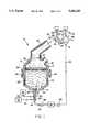
- FIG. 1is a schematic representation of one embodiment of the system of the invention.
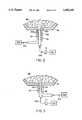
- FIG. 2is a partial section view of a tuyere of the invention.
- FIG. 3is a section view of an alternative embodiment of a tuyere of the invention.
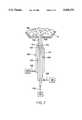
- FIG. 4is a section view of another embodiment of a tuyere of the invention.
- FIG. 5is a section view of another embodiment of the tuyere shown in FIG. 4, further including an oxidant tube.
- FIG. 6is a section view of another embodiment of the tuyere shown in FIG. 5, further including a tapered portion of a gas conduit of the tuyere.
- FIG. 7is a section view of the tuyere shown in FIG. 6, further including a nozzle, but without an oxidant tube.
- the present inventiongenerally relates to a method and system for injecting a liquid into a molten bath.
- a molten metal bathsuch as is used in a steelmaking facility, which destroys polychlorinated biphenyls and other organic wastes, optionally together with inorganic wastes.
- System 10 illustrated in FIG. 1is one embodiment of a system suitable for injecting a liquid into a molten bath according to the method of the invention.
- the systemincludes reactor 12.
- suitable reactorsinclude K-BOP, Q-BOP, argon-oxygen decarbonization furnaces (AOD), EAF, etc., such as are known in the art of steelmaking.
- Reactor 12includes upper portion 14 and lower portion 16. Feed inlet 18 at upper portion 14 of reactor 12 is suitable for directing feed into reactor 12. Off-gas outlet 20 extends from upper portion 14 and is suitable for conducting an off-gas out of reactor 12.
- Tuyere 22is disposed at lower portion 16 of reactor 12.
- Tuyere 22includes gas conduit 24 and liquid conduit 26, which is disposed within gas conduit 24.
- Shroud gas conduit 28is disposed about gas conduit 24.
- Conduit 30extends from gas source 32 to gas conduit 24.
- Conduit 34extends from liquid source 36 to liquid conduit 26 at reactor 12.
- Pump 38is disposed at conduit 34 for directing liquid from liquid source 36 through conduit 34 and liquid conduit 26 into reactor 12.
- Conduit 40extends from shroud gas source 42 to shroud gas conduit 28 of tuyere 22.
- Bottom-tapping spout 44extends from lower portion 16 and is suitable for removal of at least a portion of a molten bath from reactor 12.
- An additional bottom-tapping spout, not shown,can be provided as a means of continuously or intermittently removing at least a portion of a molten bath from reactor 12.
- Material in reactor 12can also be removed by other means, such as are well known in the art of steelmaking. For example, material can be removed from reactor 12 by rotating reactor 12 and employing a launder, not shown, extending from feed inlet 18. Alternatively, the launder can extend into reactor 12 through a tap-hole, not shown.
- Induction coil 46is disposed at lower portion 16 for heating a molten bath within reactor 12 or for initiating generation of heat within reactor 12. It is to be understood that, alternatively, reactor 12 can be heated by other suitable means, such as by oxyfuel burners, electric arc, etc. Trunions 48 are disposed at reactor 12 for manipulation of reactor 12. Seal 50 is disposed between reactor 12 and off-gas outlet 20 and is suitable for allowing partial rotation of reactor 12 about trunions 48 without breaking seal 50.
- Heat exchanger 52is disposed at off-gas outlet 20.
- Heat exchanger 52can be any suitable heat exchanger for cooling off-gas discharged from reactor 12. Examples of suitable heat exchangers include water-cooled hoods, shell-and-tube heat exchangers, etc.
- heat exchanger 52is a shell-and-tube heat exchanger which includes off-gas side 54 defining off-gas inlet 56 and off-gas outlet 58.
- Heat exchanger 52also includes coolant side 60 which defines coolant inlet 62 and coolant outlet 64.
- Conduit 66extends between coolant source 68 and coolant inlet 62 of heat exchanger 52.
- a coolant which is suitable for cooling off-gasis disposed at coolant source 68. Examples of suitable cooling media include, for example, water, ethylene glycol, ethylbenzene, alcohols, etc.
- Scrubber 70is disposed at off-gas outlet 58 of heat exchanger 52. Scrubber 70 is suitable for removing a component of the off-gas to form a stream which can be directed into reactor 12 or disposed of by some other suitable means.
- An example of a suitable scrubberis a caustic-type scrubber. Scrubber 70 defines off-gas inlet 72, scrubber fluid inlet 74, scrubber fluid outlet 76, and off-gas outlet 78.
- Conduit 80extends between scrubber fluid source 82 and scrubber fluid inlet 74 of scrubber 70.
- a scrubber fluid which is suitable for separating at least one component of off-gas from the off-gasis disposed at scrubber fluid source 82. Examples of suitable scrubber fluids include sodium hydroxide (NaOH), calcium hydroxide (Ca(OH) 2 ), etc.
- Conduit 84extends from scrubber outlet 76 to liquid source 36.
- Pump 86is disposed at conduit 84 for directing scrubber fluid from scrubber 70 to liquid source 36.
- a reaction zone within system 10includes molten bath 88, vitreous layer 90 and gaseous layer 92.
- molten bath 88is formed by at least partially filling reactor 12 with a suitable metal. The metal is then heated to form molten bath 88 by activating induction coil 46 or by some other suitable means, not shown.
- a molten bath having immiscible molten metal phasesis to be formed, for example, two immiscible metals are introduced to reactor 12. The metals separate during melting to form a first molten metal phase and a second molten metal phase, which is substantially immiscible in the first molten metal phase.
- Vitreous layer 90is disposed on molten bath 88. Vitreous layer 90 is substantially immiscible with molten metal bath 88. Alternatively, system 10 does not include vitreous layer 90. Vitreous layer 90 includes at least one metal oxide. Typically, vitreous layer 90 is substantially fluid and free radicals and other gases can pass from molten bath 88 across vitreous layer 90. In one embodiment, vitreous layer 90 has a lower thermoconductivity than that of molten bath 88. Radiant loss of heat from molten bath 88 can thereby be reduced to below the radiant heat loss for molten bath 88 in the absence of a vitreous layer. It is to be understood that vitreous layer 90 can include more than one metal oxide. Vitreous layer 90 can also include more than one phase.
- Vitreous layer 90can be formed by directing suitable materials into reactor 12 and then heating the materials to a sufficient temperature to melt the materials. Vitreous layer 90 can also comprise slag or sludge contaminated with toxic metals or other valuable metals or their oxides that are suitable for reclamation. The materials can be directed onto the top of vitreous layer 90 or injected into molten bath 88, using methods such as are well known in the art of steelmaking.
- Gaseous layer 92extends from vitreous layer 90 at upper portion 14 of reactor 12 through off-gas outlet 20 to scrubber 70.
- Gaseous layer 92includes off-gas formed in molten bath 88 and in vitreous layer 90. Off-gas is at least partially formed by volatilization and reaction of components of the liquid and gaseous feed to form gases, such as carbon monoxide and, optionally, carbon dioxide.
- liquidis directed from liquid source 36 through conduit 34 and liquid conduit 26 into molten bath 88 by activation of pump 38.
- the liquidhas a nucleation temperature which is lower than that of the temperature of molten bath 88, whereby the liquid will substantially volatilize or decompose upon exposure to the operating conditions of system 10 in molten bath 88.
- Suitable operating conditions of system 10include a temperature of molten bath 88 which is sufficient to volatilize or decompose a substantial portion of the liquid component of the liquid dispersion directed into molten bath 88.
- An example of a suitable temperatureis a temperature above about 500°-600° C.
- a suitable gasis directed from gas source 32 through conduit 30 and gas conduit 24 into molten bath 88.
- the gasis directed through gas conduit 24 into molten bath 88 by a suitable means.
- An example of suitable means by which the gas is directed through gas conduit 24 into molten bath 88includes pressurization of gas source 32.
- a suitable shroud gasis directed from shroud gas source 42 through conduit 40 and shroud gas conduit 28 to cool tuyere 22 while gas and liquid are directed into molten bath 88 through gas and liquid conduits 24, 26, respectively.
- suitable shroud gasesinclude methane, propane, natural gas, etc.
- the velocity at which the gas is directed through gas conduit 24 into molten bath 88is sufficient to cause liquid discharged from liquid conduit 26 to substantially atomize and thereby form a suitable liquid dispersion of the atomized liquid and the gas.
- the gas directed through gas conduit 24can have a Froude number of greater than, for example, about 2400, to thereby prevent molten metal of molten bath 88 from entering gas tuyere 22 and thereby blocking introduction of gas into molten bath 88.
- the gas employed for forming the liquid dispersionis substantially inert under the conditions of the molten bath 88.
- gasesinclude argon, helium, etc.
- the gascan be reactive with a component of molten bath 88 or with a liquid directed into molten bath 88.
- reactive gasesinclude oxygen, hydrogen, propane, methane, etc.
- the liquidcan be combustible under the operating conditions of system 10 in molten bath 88.
- the liquidcan also be a liquid hazardous waste which substantially volatilizes or decomposes under the operating conditions of system 10 in molten bath 88. Specific examples of suitable liquid wastes include polychlorinated biphenyls, etc.
- the liquid dispersionincludes a liquid phase dispersed in a gas phase.
- the liquid phase of a suitable liquid dispersionhas a ratio of surface area to volume of the liquid which is sufficient to cause an accumulated amount of the liquid phase in molten bath 88 to be less than that which would occur by injection of a continuous stream of the liquid into molten bath 88.
- the "accumulated amount of the liquid phase,” as that term is defined herein,means the amount of liquid phase which is present in molten bath 88 under the operating conditions of system 10 at steady state conditions.
- the accumulated amount of the liquid phase in molten bath 88is sufficiently less than that which would occur by injection of substantially continuous stream of the liquid to cause the liquid to substantially volatilize or decompose without significant disruption of the integrity of molten bath 88, such as by an explosive volatilization or explosive combustion of the accumulated liquid.
- An example of a suitable ratio of surface area to volume of the liquid phase of the liquid dispersionis greater than about 6 ⁇ 10 3 (1/m).
- the liquid dispersionis then injected into molten bath 88.
- the rate at which the liquid dispersion is directed into molten bath 88is sufficient to cause liquid of the liquid phase to volatilize or decompose at a rate which is sufficient to cause the accumulation of the liquid phase in the bath to be significantly less than that which would occur by injection of a continuous stream of the liquid into molten bath 88.
- molten bath 88Upon introduction of the liquid dispersion into molten bath 88, a substantial portion of the liquid volatilizes or decomposes.
- molten bath 88can be agitated to further particulate gas which is directed into molten metal bath 80.
- An example of a suitable method for agitating molten metal bath 80is induction stirring or gas injection to induce stirring.
- the volatilized liquid component or decomposition products of the liquid dispersion in molten bath 88can react with components of the gas phase or with components of molten bath 88. Consequent reaction products can dissolve in molten bath 88 or be discharged as gaseous products from molten bath 88.
- Other components of off-gas formed in reactor 12can include hydrogen gas, water, etc., formed by chemical transformation of other components of the liquid or gas phases directed into molten bath 88, such as organic compounds.
- off-gas formed in reactor 12is conducted from reactor 12 through off-gas outlet 20 to heat exchanger 52.
- the off-gasis cooled in heat exchanger 52 by conducting the off-gas through off-gas side 54 of heat exchanger 52 and by directing a suitable cooling medium through coolant side 60 of heat exchanger 52.
- the Off-gasis conducted into heat exchanger 52 through off-gas inlet 56 and then through off-gas outlet 58.
- the coolantis directed from source 68 through coolant inlet 62 of heat exchanger 52 by a suitable means, such as by use of a pump, not shown.
- the coolantis directed through coolant side 60 of heat exchanger 52, thereby cooling the off-gas, and is then directed out of heat exchanger 52 through coolant outlet 64.
- the coolantis conducted through heat exchanger 52 at a rate sufficient to cool the off-gas to a temperature suitable for subsequent formation of a liquid composition from the cooled off-gas.
- the off-gasis cooled to a temperature below about 500° C.
- the off-gasis directed out of off-gas outlet 58 to scrubber 70 in order to expose the off-gas to conditions sufficient to remove at least one component from the off-gas for further processing, such as for return to reactor 12 or for treatment in an additional reactor, not shown.
- Examples of methods for treatment of the off-gas, including its separation and processing of components of the off gas,are disclosed in U.S. Patent Application Ser. No. 07/737,048, the teachings of which are included herein by reference.
- the gasescan be directed to a condenser and recovered by condensation.
- the gaseous metal vaporscan be condensed and the liquid metal and alloys can be tapped in a suitable manner, such as by scrubbing.
- material that accumulates at the condensercan be recycled to the reaction zone.
- Nonvolatile metalscan be tapped as an alloy.
- carbon monoxidecan be a recoverable product of the method.
- a liquid stream formed by scrubbing the off-gascan be directed through conduit 84 to liquid source 36.
- the system of the inventionincludes tuyere 94 at reactor 12.
- Tuyere 94includes outer tube 96 and inner tube 98, which is concentrically disposed within outer tube 96.
- Inner tube 98is sealed at end 100 and defines a plurality of perforations 102.
- End 100is recessed within outer tube 96.
- the distance of end 100 of inner tube 98 from molten bath 88is sufficient to prevent damage to inner tube 98 by molten bath 88 as the wall of reactor 12 wears down during operation of the system 10.
- Inner tube 98can be retractable along a major axis of outer tube 96 to thereby prevent contact between molten bath 88 and inner tube 98 as the wall of reactor 12 wears down during operation of system 10.
- Tuyere 94is disposed at reactor 11 at a point below an upper surface of molten bath 88 within reactor 12.
- Conduit 104extends from gas source 106 to outer tube 96 of tuyere 94.
- Conduit 108extends from liquid source 110 to inner tube 98.
- Liquidis directed from liquid source 110 through inner tube 98 by pump 111 at conduit 108 and passes through perforations 102.
- Gasis directed from gas source 106 through conduit 104 and outer tube 96 into molten bath 88.
- the velocity at which gas is directed through outer tube 96 of tuyere 94is sufficient to substantially atomize liquid discharged from inner tube 98 through perforations 102.
- the atomized liquid and the gasform a suitable liquid dispersion of atomized liquid in the gas.
- the ratio of surface area to volume of the liquid phase of the liquid dispersion formed by tuyere 94is sufficient to cause an accumulated amount of the liquid phase in molten bath 88 to be less than that which would occur by injection of a substantially continuous stream of the liquid in molten bath 88.
- the liquid dispersionis directed from tuyere 94 into molten bath 88.
- the atomized liquid of the liquid dispersion in molten bath 88substantially volatilizes or decomposes in molten bath 88.
- the volatilized liquid component or decomposition productsare then available for reaction, under the operating conditions of system 10, with components of the gas phase or with components of molten bath 88.
- tuyere 112includes outer tube 114 which abuts reactor 12.
- Inner tube 116passes through reactor 12 and defines a plurality of perforations 118 which provide fluid communication between reactor 12 and outer tube 114.
- Liquidis directed by pump 111 from liquid source 110 through liquid conduit 108 and into outer tube 114 of tuyere 112.
- a liquidthen passes through perforations 118 of inner tube 116.
- Gasis simultaneously directed by suitable means from gas source 106 through gas conduit 104 and inner tube 116. The velocity at which gas is directed through inner tube 116 is sufficient to substantially atomize liquid passing through perforations 118 of inner tube 116.
- Atomization of the liquid directed into inner tube 116causes a suitable liquid dispersion to form of the liquid and the gas.
- the liquid dispersionis directed into molten bath 88.
- the liquid particles in the liquid dispersionvolatilize or decompose under the operating conditions of system 10 in molten bath 88.
- tuyere 120includes liquid conduit 122, having liquid-discharge end 124.
- Liquid conduit 122is disposed within gas conduit 126.
- Gas conduit 126includes gas-discharge end 128.
- Liquid-discharge end 124 of liquid conduit 122is recessed within gas conduit 126 at a distance from gas-discharge end 124 which is sufficient to enable an atomizing gas, which is directed through gas conduit 126, to atomize liquid discharged from liquid conduit 122 before the liquid contacts molten bath 88 into which the gas and the liquid are discharged.
- Gas-discharge end 128 of gas conduit 126is disposed at reactor 12 at a point below the surface of molten bath 88 disposed within reactor 12. Examples of suitable atomizing gases for direction through gas conduit 126 to atomize liquid discharged from liquid conduit 122 include steam, propane, nitrogen gas, etc.
- Coolant tube 130is disposed about gas conduit 126.
- a suitable liquidis directed from liquid source 132 through conduit 134 and through liquid conduit 122, and is discharged from liquid conduit 122 at liquid-discharge end 124.
- An atomizing gasis directed from gas source 136 through conduit 138 and gas conduit 126 simultaneously and conjointly with discharge of liquid from liquid-discharge end 124 of liquid Conduit 122.
- the rate at which the atomizing gas is directed through gas conduit 126is sufficient to cause the velocity of the atomizing gas through gas conduit 126 at liquid discharge end 124 of liquid conduit 122 to be sufficient, relative to the rate of liquid discharge from liquid-discharge end 124, to cause the liquid discharged from liquid-discharge end 124 to substantially atomize within gas conduit 126 prior to introduction of the liquid into molten bath 88 within reactor 12 and to form a suitable liquid dispersion. Further, the rate at which gas is directed through gas conduit 126 is sufficient to prevent intrusion of molten bath 88 into tuyere 120.
- coolantis simultaneously and conjointly directed from coolant source 140 through conduit 142 and coolant tube 130 of tuyere 120 at a rate which is sufficient to cool molten bath 88 in a portion of molten bath 88 which is proximate to gas-discharge end 128 of tuyere 120.
- suitable coolantsinclude propane, methane, etc.
- tuyerefurther includes oxidant tube 144 disposed within coolant tube 130 but also disposed about gas conduit 126.
- Oxidantis directed from oxidant source 146 through conduit 148 and oxidant tube 144 for combination with the liquid dispersion of the atomized liquid and gas formed within gas conduit 126.
- the oxidant and liquid dispersioncombine within molten bath 88 to cause, for example, combustion of the liquid component of the liquid dispersion following volatilization of the atomized liquid within molten bath 88.
- suitable oxidantsinclude, for example, oxygen gas, air, chlorine gas, iron oxide, etc.
- FIG. 6is another optional embodiment of tuyere 120, wherein gas conduit 126 includes tapered portion 150 which is proximate to liquid-discharge end 124 of liquid conduit 122.
- Gas conduit 126further includes an atomizing portion 152 which extends between tapered portion 150 and gas-discharge end 128.
- atomizing portion 152has a substantially constant diameter.
- oxidant tube 144 and coolant tube 130are also tapered about tapered portion 150 of gas conduit 126.
- Atomizing gas which is directed through gas conduit 126accelerates at tapered portion 150 of gas conduit 126, thereby facilitating atomization of liquid discharged from liquid-discharge end 124 of liquid conduit 122.
- the liquidsubstantially atomizes in atomizing portion 152 of gas conduit 126 to form a suitable liquid dispersion.
- nozzle 154is disposed at liquid-discharge end 124 of liquid conduit 122 and within gas conduit 126.
- An example of a suitable nozzleis a spinner-type nozzle.
- Nozzle 154channels atomizing gas directed through gas conduit 126 into the path of liquid discharged from liquid conduit 122, thereby further facilitating atomization of the liquid prior to introduction of a resultant suitable liquid dispersion into molten bath 88.
Landscapes
- Engineering & Computer Science (AREA)
- Mechanical Engineering (AREA)
- General Engineering & Computer Science (AREA)
- Chemical & Material Sciences (AREA)
- Organic Chemistry (AREA)
- Chemical Kinetics & Catalysis (AREA)
- Manufacture And Refinement Of Metals (AREA)
Abstract
Description
Claims (13)
Priority Applications (1)
| Application Number | Priority Date | Filing Date | Title |
|---|---|---|---|
| US08/013,756US5436210A (en) | 1993-02-04 | 1993-02-04 | Method and apparatus for injection of a liquid waste into a molten bath |
Applications Claiming Priority (1)
| Application Number | Priority Date | Filing Date | Title |
|---|---|---|---|
| US08/013,756US5436210A (en) | 1993-02-04 | 1993-02-04 | Method and apparatus for injection of a liquid waste into a molten bath |
Publications (1)
| Publication Number | Publication Date |
|---|---|
| US5436210Atrue US5436210A (en) | 1995-07-25 |
Family
ID=21761594
Family Applications (1)
| Application Number | Title | Priority Date | Filing Date |
|---|---|---|---|
| US08/013,756Expired - LifetimeUS5436210A (en) | 1993-02-04 | 1993-02-04 | Method and apparatus for injection of a liquid waste into a molten bath |
Country Status (1)
| Country | Link |
|---|---|
| US (1) | US5436210A (en) |
Cited By (50)
| Publication number | Priority date | Publication date | Assignee | Title |
|---|---|---|---|---|
| US5537940A (en)* | 1993-06-08 | 1996-07-23 | Molten Metal Technology, Inc. | Method for treating organic waste |
| WO1996040373A1 (en)* | 1995-06-07 | 1996-12-19 | Molten Metal Technology, Inc. | Vaporizable material injection into molten bath |
| US5613245A (en)* | 1995-06-07 | 1997-03-18 | Molten Metal Technology, Inc. | Method and apparatus for injecting wastes into a molten bath with an ejector |
| US5615626A (en)* | 1994-10-05 | 1997-04-01 | Ausmelt Limited | Processing of municipal and other wastes |
| US5678236A (en) | 1996-01-23 | 1997-10-14 | Pedro Buarque De Macedo | Method and apparatus for eliminating volatiles or airborne entrainments when vitrifying radioactive and/or hazardous waste |
| US5803894A (en)* | 1996-12-24 | 1998-09-08 | Cement-Lock L.L.C. | Process for preparing enviromentally stable products by the remediation of contaminated sediments and soils |
| US5855666A (en)* | 1996-12-24 | 1999-01-05 | Cement-Lock Group, L.L.C. | Process for preparing environmentally stable products by the remediation of contaminated sediments and soils |
| US5866095A (en)* | 1991-07-29 | 1999-02-02 | Molten Metal Technology, Inc. | Method and system of formation and oxidation of dissolved atomic constitutents in a molten bath |
| US5908559A (en)* | 1995-05-19 | 1999-06-01 | Kreisler; Lawrence | Method for recovering and separating metals from waste streams |
| US6254782B1 (en) | 1995-05-19 | 2001-07-03 | Lawrence Kreisler | Method for recovering and separating metals from waste streams |
| US6270679B1 (en) | 1995-05-19 | 2001-08-07 | Lawrence Kreisler | Method for recovering and separating metals from waste streams |
| US6274045B1 (en) | 1995-05-19 | 2001-08-14 | Lawrence Kreisler | Method for recovering and separating metals from waste streams |
| US6717026B2 (en)* | 2001-02-27 | 2004-04-06 | Clean Technologies International Corporation | Molten metal reactor utilizing molten metal flow for feed material and reaction product entrapment |
| US6797195B1 (en) | 1995-05-19 | 2004-09-28 | Lawrence Kreisler | Method for recovering and separating metals from waste streams |
| US7402276B2 (en) | 2003-07-14 | 2008-07-22 | Cooper Paul V | Pump with rotating inlet |
| US7470392B2 (en) | 2003-07-14 | 2008-12-30 | Cooper Paul V | Molten metal pump components |
| US7507367B2 (en) | 2002-07-12 | 2009-03-24 | Cooper Paul V | Protective coatings for molten metal devices |
| US7731891B2 (en) | 2002-07-12 | 2010-06-08 | Cooper Paul V | Couplings for molten metal devices |
| WO2010130404A1 (en)* | 2009-05-14 | 2010-11-18 | SCHLÜTER, Hartwig | Method and system for performing chemical processes |
| US7906068B2 (en) | 2003-07-14 | 2011-03-15 | Cooper Paul V | Support post system for molten metal pump |
| DE102010050152A1 (en) | 2010-11-02 | 2012-05-03 | Adam Handerek | Reactor and method for at least partial decomposition, in particular depolymerization, and / or cleaning of plastic material |
| DE102010050153A1 (en) | 2010-11-02 | 2012-05-03 | Adam Handerek | Reactor and method for at least partially decomposing and / or cleaning plastic material |
| US8178037B2 (en) | 2002-07-12 | 2012-05-15 | Cooper Paul V | System for releasing gas into molten metal |
| US8337746B2 (en) | 2007-06-21 | 2012-12-25 | Cooper Paul V | Transferring molten metal from one structure to another |
| US8361379B2 (en) | 2002-07-12 | 2013-01-29 | Cooper Paul V | Gas transfer foot |
| US8366993B2 (en) | 2007-06-21 | 2013-02-05 | Cooper Paul V | System and method for degassing molten metal |
| US8444911B2 (en) | 2009-08-07 | 2013-05-21 | Paul V. Cooper | Shaft and post tensioning device |
| US8449814B2 (en) | 2009-08-07 | 2013-05-28 | Paul V. Cooper | Systems and methods for melting scrap metal |
| US8524146B2 (en) | 2009-08-07 | 2013-09-03 | Paul V. Cooper | Rotary degassers and components therefor |
| US8535603B2 (en) | 2009-08-07 | 2013-09-17 | Paul V. Cooper | Rotary degasser and rotor therefor |
| US8613884B2 (en) | 2007-06-21 | 2013-12-24 | Paul V. Cooper | Launder transfer insert and system |
| US8714914B2 (en) | 2009-09-08 | 2014-05-06 | Paul V. Cooper | Molten metal pump filter |
| US9011761B2 (en) | 2013-03-14 | 2015-04-21 | Paul V. Cooper | Ladle with transfer conduit |
| US9108244B2 (en) | 2009-09-09 | 2015-08-18 | Paul V. Cooper | Immersion heater for molten metal |
| US9156087B2 (en) | 2007-06-21 | 2015-10-13 | Molten Metal Equipment Innovations, Llc | Molten metal transfer system and rotor |
| US9205490B2 (en) | 2007-06-21 | 2015-12-08 | Molten Metal Equipment Innovations, Llc | Transfer well system and method for making same |
| US9409232B2 (en) | 2007-06-21 | 2016-08-09 | Molten Metal Equipment Innovations, Llc | Molten metal transfer vessel and method of construction |
| US9410744B2 (en) | 2010-05-12 | 2016-08-09 | Molten Metal Equipment Innovations, Llc | Vessel transfer insert and system |
| US9643247B2 (en) | 2007-06-21 | 2017-05-09 | Molten Metal Equipment Innovations, Llc | Molten metal transfer and degassing system |
| US9903383B2 (en) | 2013-03-13 | 2018-02-27 | Molten Metal Equipment Innovations, Llc | Molten metal rotor with hardened top |
| CN108061302A (en)* | 2016-11-07 | 2018-05-22 | 李江平 | The method and device of domestic garbage gasification melting is carried out using iron liquid |
| US10052688B2 (en) | 2013-03-15 | 2018-08-21 | Molten Metal Equipment Innovations, Llc | Transfer pump launder system |
| US10138892B2 (en) | 2014-07-02 | 2018-11-27 | Molten Metal Equipment Innovations, Llc | Rotor and rotor shaft for molten metal |
| US10267314B2 (en) | 2016-01-13 | 2019-04-23 | Molten Metal Equipment Innovations, Llc | Tensioned support shaft and other molten metal devices |
| US10428821B2 (en) | 2009-08-07 | 2019-10-01 | Molten Metal Equipment Innovations, Llc | Quick submergence molten metal pump |
| US10947980B2 (en) | 2015-02-02 | 2021-03-16 | Molten Metal Equipment Innovations, Llc | Molten metal rotor with hardened blade tips |
| US11149747B2 (en) | 2017-11-17 | 2021-10-19 | Molten Metal Equipment Innovations, Llc | Tensioned support post and other molten metal devices |
| US11358217B2 (en) | 2019-05-17 | 2022-06-14 | Molten Metal Equipment Innovations, Llc | Method for melting solid metal |
| US11873845B2 (en) | 2021-05-28 | 2024-01-16 | Molten Metal Equipment Innovations, Llc | Molten metal transfer device |
| US12146508B2 (en) | 2022-05-26 | 2024-11-19 | Molten Metal Equipment Innovations, Llc | Axial pump and riser |
Citations (20)
| Publication number | Priority date | Publication date | Assignee | Title |
|---|---|---|---|---|
| US370251A (en)* | 1887-09-20 | Half to edward b | ||
| US2854229A (en)* | 1953-08-26 | 1958-09-30 | American Metal Climax Inc | Oil burning tuyere |
| CA666171A (en)* | 1963-07-02 | H. Manny Erwin | Liquid fuel injection in blast furnaces | |
| US3186476A (en)* | 1961-04-14 | 1965-06-01 | Asahi Chemical Ind | Method for heating liquid by means of steam |
| US3236281A (en)* | 1963-12-19 | 1966-02-22 | United States Steel Corp | Method and apparatus for burning a mixture of liquid and gaseous fuels |
| GB1205098A (en)* | 1967-12-08 | 1970-09-16 | Ct De Rech S De Pont A Mousson | Improvements in or relating to a device for the injection of liquid fuels into blast furnaces |
| US3582053A (en)* | 1968-02-28 | 1971-06-01 | Centre Nat Rech Metall | Method and apparatus for injecting liquid fuel into a shaft furnace |
| US3608881A (en)* | 1967-03-24 | 1971-09-28 | Za Zvetni Metali K | Tuyere apparatus for using liquid fuel in the fuming process |
| US3771473A (en)* | 1971-01-20 | 1973-11-13 | Siderurgie Fse Inst Rech | Tuyere for a blast furnace and a method for operating the tuyere to atomize combustible material fed into the tuyere by a shock wave |
| GB1343901A (en)* | 1971-04-05 | 1974-01-16 | ||
| US3997334A (en)* | 1972-04-28 | 1976-12-14 | Centre De Recherches Metallurgiques-Centrum Voor Research In De Metallurgie | Introduction of a liquid into a receptacle such as a converter |
| US4191154A (en)* | 1977-08-29 | 1980-03-04 | Toyota Jidosha Kogyo Kabushiki Kaisha | Evaporated fuel vapor control device for use in an internal combustion engine |
| US4574714A (en)* | 1984-11-08 | 1986-03-11 | United States Steel Corporation | Destruction of toxic chemicals |
| US4602574A (en)* | 1984-11-08 | 1986-07-29 | United States Steel Corporation | Destruction of toxic organic chemicals |
| US4647019A (en)* | 1986-04-01 | 1987-03-03 | Union Carbide Corporation | Very small refining vessel |
| US4657586A (en)* | 1985-10-25 | 1987-04-14 | Union Carbide Corporation | Submerged combustion in molten materials |
| US4708738A (en)* | 1986-04-01 | 1987-11-24 | Union Carbide Corporation | Method for refining very small heats of molten metal |
| US4754951A (en)* | 1987-08-14 | 1988-07-05 | Union Carbide Corporation | Tuyere assembly and positioning method |
| US5177304A (en)* | 1990-07-24 | 1993-01-05 | Molten Metal Technology, Inc. | Method and system for forming carbon dioxide from carbon-containing materials in a molten bath of immiscible metals |
| US5202100A (en)* | 1991-11-07 | 1993-04-13 | Molten Metal Technology, Inc. | Method for reducing volume of a radioactive composition |
- 1993
- 1993-02-04USUS08/013,756patent/US5436210A/ennot_activeExpired - Lifetime
Patent Citations (20)
| Publication number | Priority date | Publication date | Assignee | Title |
|---|---|---|---|---|
| US370251A (en)* | 1887-09-20 | Half to edward b | ||
| CA666171A (en)* | 1963-07-02 | H. Manny Erwin | Liquid fuel injection in blast furnaces | |
| US2854229A (en)* | 1953-08-26 | 1958-09-30 | American Metal Climax Inc | Oil burning tuyere |
| US3186476A (en)* | 1961-04-14 | 1965-06-01 | Asahi Chemical Ind | Method for heating liquid by means of steam |
| US3236281A (en)* | 1963-12-19 | 1966-02-22 | United States Steel Corp | Method and apparatus for burning a mixture of liquid and gaseous fuels |
| US3608881A (en)* | 1967-03-24 | 1971-09-28 | Za Zvetni Metali K | Tuyere apparatus for using liquid fuel in the fuming process |
| GB1205098A (en)* | 1967-12-08 | 1970-09-16 | Ct De Rech S De Pont A Mousson | Improvements in or relating to a device for the injection of liquid fuels into blast furnaces |
| US3582053A (en)* | 1968-02-28 | 1971-06-01 | Centre Nat Rech Metall | Method and apparatus for injecting liquid fuel into a shaft furnace |
| US3771473A (en)* | 1971-01-20 | 1973-11-13 | Siderurgie Fse Inst Rech | Tuyere for a blast furnace and a method for operating the tuyere to atomize combustible material fed into the tuyere by a shock wave |
| GB1343901A (en)* | 1971-04-05 | 1974-01-16 | ||
| US3997334A (en)* | 1972-04-28 | 1976-12-14 | Centre De Recherches Metallurgiques-Centrum Voor Research In De Metallurgie | Introduction of a liquid into a receptacle such as a converter |
| US4191154A (en)* | 1977-08-29 | 1980-03-04 | Toyota Jidosha Kogyo Kabushiki Kaisha | Evaporated fuel vapor control device for use in an internal combustion engine |
| US4574714A (en)* | 1984-11-08 | 1986-03-11 | United States Steel Corporation | Destruction of toxic chemicals |
| US4602574A (en)* | 1984-11-08 | 1986-07-29 | United States Steel Corporation | Destruction of toxic organic chemicals |
| US4657586A (en)* | 1985-10-25 | 1987-04-14 | Union Carbide Corporation | Submerged combustion in molten materials |
| US4647019A (en)* | 1986-04-01 | 1987-03-03 | Union Carbide Corporation | Very small refining vessel |
| US4708738A (en)* | 1986-04-01 | 1987-11-24 | Union Carbide Corporation | Method for refining very small heats of molten metal |
| US4754951A (en)* | 1987-08-14 | 1988-07-05 | Union Carbide Corporation | Tuyere assembly and positioning method |
| US5177304A (en)* | 1990-07-24 | 1993-01-05 | Molten Metal Technology, Inc. | Method and system for forming carbon dioxide from carbon-containing materials in a molten bath of immiscible metals |
| US5202100A (en)* | 1991-11-07 | 1993-04-13 | Molten Metal Technology, Inc. | Method for reducing volume of a radioactive composition |
Cited By (138)
| Publication number | Priority date | Publication date | Assignee | Title |
|---|---|---|---|---|
| US5866095A (en)* | 1991-07-29 | 1999-02-02 | Molten Metal Technology, Inc. | Method and system of formation and oxidation of dissolved atomic constitutents in a molten bath |
| US5537940A (en)* | 1993-06-08 | 1996-07-23 | Molten Metal Technology, Inc. | Method for treating organic waste |
| US5615626A (en)* | 1994-10-05 | 1997-04-01 | Ausmelt Limited | Processing of municipal and other wastes |
| US6274045B1 (en) | 1995-05-19 | 2001-08-14 | Lawrence Kreisler | Method for recovering and separating metals from waste streams |
| US6797195B1 (en) | 1995-05-19 | 2004-09-28 | Lawrence Kreisler | Method for recovering and separating metals from waste streams |
| US5908559A (en)* | 1995-05-19 | 1999-06-01 | Kreisler; Lawrence | Method for recovering and separating metals from waste streams |
| US6254782B1 (en) | 1995-05-19 | 2001-07-03 | Lawrence Kreisler | Method for recovering and separating metals from waste streams |
| US6270679B1 (en) | 1995-05-19 | 2001-08-07 | Lawrence Kreisler | Method for recovering and separating metals from waste streams |
| WO1996040373A1 (en)* | 1995-06-07 | 1996-12-19 | Molten Metal Technology, Inc. | Vaporizable material injection into molten bath |
| US5613245A (en)* | 1995-06-07 | 1997-03-18 | Molten Metal Technology, Inc. | Method and apparatus for injecting wastes into a molten bath with an ejector |
| US5679132A (en)* | 1995-06-07 | 1997-10-21 | Molten Metal Technology, Inc. | Method and system for injection of a vaporizable material into a molten bath |
| US5678236A (en) | 1996-01-23 | 1997-10-14 | Pedro Buarque De Macedo | Method and apparatus for eliminating volatiles or airborne entrainments when vitrifying radioactive and/or hazardous waste |
| US5803894A (en)* | 1996-12-24 | 1998-09-08 | Cement-Lock L.L.C. | Process for preparing enviromentally stable products by the remediation of contaminated sediments and soils |
| US5855666A (en)* | 1996-12-24 | 1999-01-05 | Cement-Lock Group, L.L.C. | Process for preparing environmentally stable products by the remediation of contaminated sediments and soils |
| US7449156B2 (en)* | 2001-02-27 | 2008-11-11 | Clean Technologies International Corporation | Molten metal reactor utilizing molten metal flow for feed material and reaction product entrapment |
| US20040191138A1 (en)* | 2001-02-27 | 2004-09-30 | Wagner Anthony S. | Molten metal reactor utilizing molten metal flow for feed material and reaction product entrapment |
| US6717026B2 (en)* | 2001-02-27 | 2004-04-06 | Clean Technologies International Corporation | Molten metal reactor utilizing molten metal flow for feed material and reaction product entrapment |
| US8409495B2 (en) | 2002-07-12 | 2013-04-02 | Paul V. Cooper | Rotor with inlet perimeters |
| US9435343B2 (en) | 2002-07-12 | 2016-09-06 | Molten Meal Equipment Innovations, LLC | Gas-transfer foot |
| US8361379B2 (en) | 2002-07-12 | 2013-01-29 | Cooper Paul V | Gas transfer foot |
| US7507367B2 (en) | 2002-07-12 | 2009-03-24 | Cooper Paul V | Protective coatings for molten metal devices |
| US7731891B2 (en) | 2002-07-12 | 2010-06-08 | Cooper Paul V | Couplings for molten metal devices |
| US8529828B2 (en) | 2002-07-12 | 2013-09-10 | Paul V. Cooper | Molten metal pump components |
| US8440135B2 (en) | 2002-07-12 | 2013-05-14 | Paul V. Cooper | System for releasing gas into molten metal |
| US8178037B2 (en) | 2002-07-12 | 2012-05-15 | Cooper Paul V | System for releasing gas into molten metal |
| US8110141B2 (en) | 2002-07-12 | 2012-02-07 | Cooper Paul V | Pump with rotating inlet |
| US9034244B2 (en) | 2002-07-12 | 2015-05-19 | Paul V. Cooper | Gas-transfer foot |
| US7402276B2 (en) | 2003-07-14 | 2008-07-22 | Cooper Paul V | Pump with rotating inlet |
| US8501084B2 (en) | 2003-07-14 | 2013-08-06 | Paul V. Cooper | Support posts for molten metal pumps |
| US8475708B2 (en) | 2003-07-14 | 2013-07-02 | Paul V. Cooper | Support post clamps for molten metal pumps |
| US8075837B2 (en) | 2003-07-14 | 2011-12-13 | Cooper Paul V | Pump with rotating inlet |
| US7906068B2 (en) | 2003-07-14 | 2011-03-15 | Cooper Paul V | Support post system for molten metal pump |
| US7470392B2 (en) | 2003-07-14 | 2008-12-30 | Cooper Paul V | Molten metal pump components |
| US20080304970A1 (en)* | 2003-07-14 | 2008-12-11 | Cooper Paul V | Pump with rotating inlet |
| US8337746B2 (en) | 2007-06-21 | 2012-12-25 | Cooper Paul V | Transferring molten metal from one structure to another |
| US9862026B2 (en) | 2007-06-21 | 2018-01-09 | Molten Metal Equipment Innovations, Llc | Method of forming transfer well |
| US11103920B2 (en) | 2007-06-21 | 2021-08-31 | Molten Metal Equipment Innovations, Llc | Transfer structure with molten metal pump support |
| US11130173B2 (en) | 2007-06-21 | 2021-09-28 | Molten Metal Equipment Innovations, LLC. | Transfer vessel with dividing wall |
| US11020798B2 (en) | 2007-06-21 | 2021-06-01 | Molten Metal Equipment Innovations, Llc | Method of transferring molten metal |
| US10562097B2 (en) | 2007-06-21 | 2020-02-18 | Molten Metal Equipment Innovations, Llc | Molten metal transfer system and rotor |
| US11167345B2 (en) | 2007-06-21 | 2021-11-09 | Molten Metal Equipment Innovations, Llc | Transfer system with dual-flow rotor |
| US11185916B2 (en) | 2007-06-21 | 2021-11-30 | Molten Metal Equipment Innovations, Llc | Molten metal transfer vessel with pump |
| US10458708B2 (en) | 2007-06-21 | 2019-10-29 | Molten Metal Equipment Innovations, Llc | Transferring molten metal from one structure to another |
| US10352620B2 (en) | 2007-06-21 | 2019-07-16 | Molten Metal Equipment Innovations, Llc | Transferring molten metal from one structure to another |
| US11759854B2 (en) | 2007-06-21 | 2023-09-19 | Molten Metal Equipment Innovations, Llc | Molten metal transfer structure and method |
| US10345045B2 (en) | 2007-06-21 | 2019-07-09 | Molten Metal Equipment Innovations, Llc | Vessel transfer insert and system |
| US8613884B2 (en) | 2007-06-21 | 2013-12-24 | Paul V. Cooper | Launder transfer insert and system |
| US10274256B2 (en) | 2007-06-21 | 2019-04-30 | Molten Metal Equipment Innovations, Llc | Vessel transfer systems and devices |
| US8753563B2 (en) | 2007-06-21 | 2014-06-17 | Paul V. Cooper | System and method for degassing molten metal |
| US10195664B2 (en) | 2007-06-21 | 2019-02-05 | Molten Metal Equipment Innovations, Llc | Multi-stage impeller for molten metal |
| US9017597B2 (en) | 2007-06-21 | 2015-04-28 | Paul V. Cooper | Transferring molten metal using non-gravity assist launder |
| US9566645B2 (en) | 2007-06-21 | 2017-02-14 | Molten Metal Equipment Innovations, Llc | Molten metal transfer system and rotor |
| US10072891B2 (en) | 2007-06-21 | 2018-09-11 | Molten Metal Equipment Innovations, Llc | Transferring molten metal using non-gravity assist launder |
| US9982945B2 (en) | 2007-06-21 | 2018-05-29 | Molten Metal Equipment Innovations, Llc | Molten metal transfer vessel and method of construction |
| US9156087B2 (en) | 2007-06-21 | 2015-10-13 | Molten Metal Equipment Innovations, Llc | Molten metal transfer system and rotor |
| US9409232B2 (en) | 2007-06-21 | 2016-08-09 | Molten Metal Equipment Innovations, Llc | Molten metal transfer vessel and method of construction |
| US9925587B2 (en) | 2007-06-21 | 2018-03-27 | Molten Metal Equipment Innovations, Llc | Method of transferring molten metal from a vessel |
| US9205490B2 (en) | 2007-06-21 | 2015-12-08 | Molten Metal Equipment Innovations, Llc | Transfer well system and method for making same |
| US9909808B2 (en) | 2007-06-21 | 2018-03-06 | Molten Metal Equipment Innovations, Llc | System and method for degassing molten metal |
| US8366993B2 (en) | 2007-06-21 | 2013-02-05 | Cooper Paul V | System and method for degassing molten metal |
| US9855600B2 (en) | 2007-06-21 | 2018-01-02 | Molten Metal Equipment Innovations, Llc | Molten metal transfer system and rotor |
| US9383140B2 (en) | 2007-06-21 | 2016-07-05 | Molten Metal Equipment Innovations, Llc | Transferring molten metal from one structure to another |
| US9643247B2 (en) | 2007-06-21 | 2017-05-09 | Molten Metal Equipment Innovations, Llc | Molten metal transfer and degassing system |
| US9581388B2 (en) | 2007-06-21 | 2017-02-28 | Molten Metal Equipment Innovations, Llc | Vessel transfer insert and system |
| US9375693B2 (en) | 2009-05-14 | 2016-06-28 | Adam Handerek | Method and system for performing chemical processes |
| CN102439122B (en)* | 2009-05-14 | 2015-10-21 | 亚当·汉德雷克 | Methods and apparatus for carrying out chemical processes |
| CN102439122A (en)* | 2009-05-14 | 2012-05-02 | 亚当·汉德雷克 | Methods and apparatus for carrying out chemical processes |
| WO2010130404A1 (en)* | 2009-05-14 | 2010-11-18 | SCHLÜTER, Hartwig | Method and system for performing chemical processes |
| US9422942B2 (en) | 2009-08-07 | 2016-08-23 | Molten Metal Equipment Innovations, Llc | Tension device with internal passage |
| US8444911B2 (en) | 2009-08-07 | 2013-05-21 | Paul V. Cooper | Shaft and post tensioning device |
| US9470239B2 (en) | 2009-08-07 | 2016-10-18 | Molten Metal Equipment Innovations, Llc | Threaded tensioning device |
| US8524146B2 (en) | 2009-08-07 | 2013-09-03 | Paul V. Cooper | Rotary degassers and components therefor |
| US9506129B2 (en) | 2009-08-07 | 2016-11-29 | Molten Metal Equipment Innovations, Llc | Rotary degasser and rotor therefor |
| US10428821B2 (en) | 2009-08-07 | 2019-10-01 | Molten Metal Equipment Innovations, Llc | Quick submergence molten metal pump |
| US9382599B2 (en) | 2009-08-07 | 2016-07-05 | Molten Metal Equipment Innovations, Llc | Rotary degasser and rotor therefor |
| US12163536B2 (en) | 2009-08-07 | 2024-12-10 | Molten Metal Equipment Innovations, Llc | Quick submergence molten metal pump |
| US9377028B2 (en) | 2009-08-07 | 2016-06-28 | Molten Metal Equipment Innovations, Llc | Tensioning device extending beyond component |
| US9657578B2 (en) | 2009-08-07 | 2017-05-23 | Molten Metal Equipment Innovations, Llc | Rotary degassers and components therefor |
| US8535603B2 (en) | 2009-08-07 | 2013-09-17 | Paul V. Cooper | Rotary degasser and rotor therefor |
| US9328615B2 (en) | 2009-08-07 | 2016-05-03 | Molten Metal Equipment Innovations, Llc | Rotary degassers and components therefor |
| US10570745B2 (en) | 2009-08-07 | 2020-02-25 | Molten Metal Equipment Innovations, Llc | Rotary degassers and components therefor |
| US8449814B2 (en) | 2009-08-07 | 2013-05-28 | Paul V. Cooper | Systems and methods for melting scrap metal |
| US9464636B2 (en) | 2009-08-07 | 2016-10-11 | Molten Metal Equipment Innovations, Llc | Tension device graphite component used in molten metal |
| US9080577B2 (en) | 2009-08-07 | 2015-07-14 | Paul V. Cooper | Shaft and post tensioning device |
| US8714914B2 (en) | 2009-09-08 | 2014-05-06 | Paul V. Cooper | Molten metal pump filter |
| US10309725B2 (en) | 2009-09-09 | 2019-06-04 | Molten Metal Equipment Innovations, Llc | Immersion heater for molten metal |
| US9108244B2 (en) | 2009-09-09 | 2015-08-18 | Paul V. Cooper | Immersion heater for molten metal |
| US9482469B2 (en) | 2010-05-12 | 2016-11-01 | Molten Metal Equipment Innovations, Llc | Vessel transfer insert and system |
| US9410744B2 (en) | 2010-05-12 | 2016-08-09 | Molten Metal Equipment Innovations, Llc | Vessel transfer insert and system |
| DE102010050153A1 (en) | 2010-11-02 | 2012-05-03 | Adam Handerek | Reactor and method for at least partially decomposing and / or cleaning plastic material |
| WO2012072061A1 (en) | 2010-11-02 | 2012-06-07 | SCHLÜTER, Hartwig | Reactor and process for at least partially decomposing and/or cleaning plastic material |
| DE102010050153B4 (en)* | 2010-11-02 | 2012-10-25 | Adam Handerek | Reactor and method for at least partially decomposing and / or cleaning plastic material |
| WO2012059091A1 (en) | 2010-11-02 | 2012-05-10 | SCHLÜTER, Hartwig | Reactor and method for the at least partial decomposition, in particular depolymerization, and/or purification of plastic material |
| DE102010050152B4 (en)* | 2010-11-02 | 2016-02-11 | Adam Handerek | Reactor and method for at least partial decomposition, in particular depolymerization, and / or cleaning of plastic material |
| CN103282462B (en)* | 2010-11-02 | 2015-11-25 | H·施吕特 | Reactor and method for at least partially decomposing, in particular depolymerizing and/or purifying plastic material |
| RU2587184C2 (en)* | 2010-11-02 | 2016-06-20 | ШЛЮТЕР Хартвиг | Reactor and method for at least partial decomposition, particularly, depolymerisation and/or cleaning of polymer material |
| CN103282462A (en)* | 2010-11-02 | 2013-09-04 | H·施吕特 | Reactor and method for at least partial decomposition, in particular depolymerization and/or purification of plastic materials |
| DE102010050152A1 (en) | 2010-11-02 | 2012-05-03 | Adam Handerek | Reactor and method for at least partial decomposition, in particular depolymerization, and / or cleaning of plastic material |
| US10641279B2 (en) | 2013-03-13 | 2020-05-05 | Molten Metal Equipment Innovations, Llc | Molten metal rotor with hardened tip |
| US9903383B2 (en) | 2013-03-13 | 2018-02-27 | Molten Metal Equipment Innovations, Llc | Molten metal rotor with hardened top |
| US11391293B2 (en) | 2013-03-13 | 2022-07-19 | Molten Metal Equipment Innovations, Llc | Molten metal rotor with hardened top |
| US10126058B2 (en) | 2013-03-14 | 2018-11-13 | Molten Metal Equipment Innovations, Llc | Molten metal transferring vessel |
| US10302361B2 (en) | 2013-03-14 | 2019-05-28 | Molten Metal Equipment Innovations, Llc | Transfer vessel for molten metal pumping device |
| US10126059B2 (en) | 2013-03-14 | 2018-11-13 | Molten Metal Equipment Innovations, Llc | Controlled molten metal flow from transfer vessel |
| US9587883B2 (en) | 2013-03-14 | 2017-03-07 | Molten Metal Equipment Innovations, Llc | Ladle with transfer conduit |
| US9011761B2 (en) | 2013-03-14 | 2015-04-21 | Paul V. Cooper | Ladle with transfer conduit |
| US10307821B2 (en) | 2013-03-15 | 2019-06-04 | Molten Metal Equipment Innovations, Llc | Transfer pump launder system |
| US10052688B2 (en) | 2013-03-15 | 2018-08-21 | Molten Metal Equipment Innovations, Llc | Transfer pump launder system |
| US10322451B2 (en) | 2013-03-15 | 2019-06-18 | Molten Metal Equipment Innovations, Llc | Transfer pump launder system |
| US11939994B2 (en) | 2014-07-02 | 2024-03-26 | Molten Metal Equipment Innovations, Llc | Rotor and rotor shaft for molten metal |
| US10465688B2 (en) | 2014-07-02 | 2019-11-05 | Molten Metal Equipment Innovations, Llc | Coupling and rotor shaft for molten metal devices |
| US11286939B2 (en) | 2014-07-02 | 2022-03-29 | Molten Metal Equipment Innovations, Llc | Rotor and rotor shaft for molten metal |
| US10138892B2 (en) | 2014-07-02 | 2018-11-27 | Molten Metal Equipment Innovations, Llc | Rotor and rotor shaft for molten metal |
| US10947980B2 (en) | 2015-02-02 | 2021-03-16 | Molten Metal Equipment Innovations, Llc | Molten metal rotor with hardened blade tips |
| US11933324B2 (en) | 2015-02-02 | 2024-03-19 | Molten Metal Equipment Innovations, Llc | Molten metal rotor with hardened blade tips |
| US11519414B2 (en) | 2016-01-13 | 2022-12-06 | Molten Metal Equipment Innovations, Llc | Tensioned rotor shaft for molten metal |
| US11098720B2 (en) | 2016-01-13 | 2021-08-24 | Molten Metal Equipment Innovations, Llc | Tensioned rotor shaft for molten metal |
| US10641270B2 (en) | 2016-01-13 | 2020-05-05 | Molten Metal Equipment Innovations, Llc | Tensioned support shaft and other molten metal devices |
| US10267314B2 (en) | 2016-01-13 | 2019-04-23 | Molten Metal Equipment Innovations, Llc | Tensioned support shaft and other molten metal devices |
| US11098719B2 (en) | 2016-01-13 | 2021-08-24 | Molten Metal Equipment Innovations, Llc | Tensioned support shaft and other molten metal devices |
| CN108061302A (en)* | 2016-11-07 | 2018-05-22 | 李江平 | The method and device of domestic garbage gasification melting is carried out using iron liquid |
| US12385501B2 (en) | 2017-11-17 | 2025-08-12 | Molten Metal Equipment Innovations, Llc | Tensioned support post and other molten metal devices |
| US11149747B2 (en) | 2017-11-17 | 2021-10-19 | Molten Metal Equipment Innovations, Llc | Tensioned support post and other molten metal devices |
| US12031550B2 (en) | 2017-11-17 | 2024-07-09 | Molten Metal Equipment Innovations, Llc | Tensioned support post and other molten metal devices |
| US11976672B2 (en) | 2017-11-17 | 2024-05-07 | Molten Metal Equipment Innovations, Llc | Tensioned support post and other molten metal devices |
| US11759853B2 (en) | 2019-05-17 | 2023-09-19 | Molten Metal Equipment Innovations, Llc | Melting metal on a raised surface |
| US11858037B2 (en) | 2019-05-17 | 2024-01-02 | Molten Metal Equipment Innovations, Llc | Smart molten metal pump |
| US11931803B2 (en) | 2019-05-17 | 2024-03-19 | Molten Metal Equipment Innovations, Llc | Molten metal transfer system and method |
| US11931802B2 (en) | 2019-05-17 | 2024-03-19 | Molten Metal Equipment Innovations, Llc | Molten metal controlled flow launder |
| US11858036B2 (en) | 2019-05-17 | 2024-01-02 | Molten Metal Equipment Innovations, Llc | System and method to feed mold with molten metal |
| US11850657B2 (en) | 2019-05-17 | 2023-12-26 | Molten Metal Equipment Innovations, Llc | System for melting solid metal |
| US11358217B2 (en) | 2019-05-17 | 2022-06-14 | Molten Metal Equipment Innovations, Llc | Method for melting solid metal |
| US11471938B2 (en) | 2019-05-17 | 2022-10-18 | Molten Metal Equipment Innovations, Llc | Smart molten metal pump |
| US12263522B2 (en) | 2019-05-17 | 2025-04-01 | Molten Metal Equipment Innovations, Llc | Smart molten metal pump |
| US11358216B2 (en) | 2019-05-17 | 2022-06-14 | Molten Metal Equipment Innovations, Llc | System for melting solid metal |
| US11873845B2 (en) | 2021-05-28 | 2024-01-16 | Molten Metal Equipment Innovations, Llc | Molten metal transfer device |
| US12228150B2 (en) | 2021-05-28 | 2025-02-18 | Molten Metal Equipment Innovations, Llc | Molten metal transfer device |
| US12146508B2 (en) | 2022-05-26 | 2024-11-19 | Molten Metal Equipment Innovations, Llc | Axial pump and riser |
Similar Documents
| Publication | Publication Date | Title |
|---|---|---|
| US5436210A (en) | Method and apparatus for injection of a liquid waste into a molten bath | |
| US5679132A (en) | Method and system for injection of a vaporizable material into a molten bath | |
| US5395405A (en) | Method for producing hydrocarbon gas from waste | |
| US5443572A (en) | Apparatus and method for submerged injection of a feed composition into a molten metal bath | |
| US5744117A (en) | Feed processing employing dispersed molten droplets | |
| US5358549A (en) | Method of indirect chemical reduction of metals in waste | |
| US5571486A (en) | Method and apparatus for top-charging solid waste into a molten metal bath | |
| US5585532A (en) | Method for treating a gas formed from a waste in a molten metal bath | |
| US5776420A (en) | Apparatus for treating a gas formed from a waste in a molten metal bath | |
| US5435982A (en) | Method for dissociating waste in a packed bed reactor | |
| US5640709A (en) | Method and apparatus for producing a product in a regenerator furnace from impure waste containing a non-gasifiable impurity | |
| EP0600906B1 (en) | Method for oxidation in a molten bath | |
| US5858059A (en) | Method for injecting feed streams into a molten bath | |
| RU2114356C1 (en) | Method of destruction of organic wastes | |
| US5301620A (en) | Reactor and method for disassociating waste | |
| RU2105785C1 (en) | Method of processing inorganic solid wastes | |
| US5733356A (en) | Method and device for processing free-flowing materials | |
| US5385601A (en) | Process for converting aluminum dross to ladle flux for steel processing | |
| US4762554A (en) | Process to eliminate hazardous components from the electric arc furnace flue dust and recovering of metals | |
| JP2684896B2 (en) | Electric furnace dust processing apparatus and method | |
| CA2139220C (en) | Treatment of waste | |
| WO1996025202A1 (en) | Refractory barrier layer and method of formation | |
| AU4300593A (en) | Treatment of waste |
Legal Events
| Date | Code | Title | Description |
|---|---|---|---|
| AS | Assignment | Owner name:MOLTEN METAL TECHNOLOGY, INC., MASSACHUSETTS Free format text:ASSIGNMENT OF ASSIGNORS INTEREST.;ASSIGNORS:WILKINSON, MARK A.;RAUENZAHN, RICK M.;NAGEL, CHRISTOPHER J.;REEL/FRAME:006484/0746;SIGNING DATES FROM 19930329 TO 19930402 | |
| STCF | Information on status: patent grant | Free format text:PATENTED CASE | |
| AS | Assignment | Owner name:RESTART PARTNERS III, L.P., NEW YORK Free format text:SECURITY INTEREST;ASSIGNORS:MOLTEN METAL TECHNOLOGY, INC.;MMT OF TENNESSEE INC.;MMT FEDERAL HOLDINGS, INC.;AND OTHERS;REEL/FRAME:008975/0826 Effective date:19980119 Owner name:MORGENS, WATERFALL, VINTIADIS & CO., INC., NEW YOR Free format text:SECURITY INTEREST;ASSIGNORS:MOLTEN METAL TECHNOLOGY, INC.;MMT OF TENNESSEE INC.;MMT FEDERAL HOLDINGS, INC.;AND OTHERS;REEL/FRAME:008975/0826 Effective date:19980119 Owner name:RESTART PARTNERS II, L.P., NEW YORK Free format text:SECURITY INTEREST;ASSIGNORS:MOLTEN METAL TECHNOLOGY, INC.;MMT OF TENNESSEE INC.;MMT FEDERAL HOLDINGS, INC.;AND OTHERS;REEL/FRAME:008975/0826 Effective date:19980119 Owner name:ENDOWMENET RESTART L.L.C., NEW YORK Free format text:SECURITY INTEREST;ASSIGNORS:MOLTEN METAL TECHNOLOGY, INC.;MMT OF TENNESSEE INC.;MMT FEDERAL HOLDINGS, INC.;AND OTHERS;REEL/FRAME:008975/0826 Effective date:19980119 Owner name:RESTART PARTNERS, L.P., NEW YORK Free format text:SECURITY INTEREST;ASSIGNORS:MOLTEN METAL TECHNOLOGY, INC.;MMT OF TENNESSEE INC.;MMT FEDERAL HOLDINGS, INC.;AND OTHERS;REEL/FRAME:008975/0826 Effective date:19980119 Owner name:RESTART PARTNERS IV, L.P., NEW YORK Free format text:SECURITY INTEREST;ASSIGNORS:MOLTEN METAL TECHNOLOGY, INC.;MMT OF TENNESSEE INC.;MMT FEDERAL HOLDINGS, INC.;AND OTHERS;REEL/FRAME:008975/0826 Effective date:19980119 Owner name:RESTART PARTNERS V. L.P., NEW YORK Free format text:SECURITY INTEREST;ASSIGNORS:MOLTEN METAL TECHNOLOGY, INC.;MMT OF TENNESSEE INC.;MMT FEDERAL HOLDINGS, INC.;AND OTHERS;REEL/FRAME:008975/0826 Effective date:19980119 Owner name:MORGENS WATERFALL INCOME PARTNERS, NEW YORK Free format text:SECURITY INTEREST;ASSIGNORS:MOLTEN METAL TECHNOLOGY, INC.;MMT OF TENNESSEE INC.;MMT FEDERAL HOLDINGS, INC.;AND OTHERS;REEL/FRAME:008975/0826 Effective date:19980119 | |
| AS | Assignment | Owner name:MORGENS, WATERFALL, VINTIADIS & CO., INC., NEW YOR Free format text:AMENDED SECURITY AGREEMENT;ASSIGNOR:MOLTEN METAL TECHNOLOGY INC.;REEL/FRAME:009245/0763 Effective date:19980320 | |
| AS | Assignment | Owner name:RESTART PARTNERS, L.P., A DELAWARE LIMITED PART-, Free format text:AMENDED SECURITY AGREEMENT;ASSIGNORS:MOLTEN METAL TECHNOLOGY, INC., A DELAWARE CORP.;MMT OF TENNESSEE INC., A DELAWARE CORPORATION;MMT FEDERAL HOLDINGS, INC., A DELAWARE CORPORATION;AND OTHERS;REEL/FRAME:009414/0793 Effective date:19980720 Owner name:MORGENS, WATERFALL, VINTIADIS & CO., INC., NEW YOR Free format text:AMENDED SECURITY AGREEMENT;ASSIGNORS:MOLTEN METAL TECHNOLOGY, INC., A DELAWARE CORP.;MMT OF TENNESSEE INC., A DELAWARE CORPORATION;MMT FEDERAL HOLDINGS, INC., A DELAWARE CORPORATION;AND OTHERS;REEL/FRAME:009414/0793 Effective date:19980720 Owner name:RESTART PARTNERS II, L.P., A DELAWARE LIMITED, NEW Free format text:AMENDED SECURITY AGREEMENT;ASSIGNORS:MOLTEN METAL TECHNOLOGY, INC., A DELAWARE CORP.;MMT OF TENNESSEE INC., A DELAWARE CORPORATION;MMT FEDERAL HOLDINGS, INC., A DELAWARE CORPORATION;AND OTHERS;REEL/FRAME:009414/0793 Effective date:19980720 Owner name:MORGENS WATERFALL INCOME PARTNERS, A NEW YORK, NEW Free format text:AMENDED SECURITY AGREEMENT;ASSIGNORS:MOLTEN METAL TECHNOLOGY, INC., A DELAWARE CORP.;MMT OF TENNESSEE INC., A DELAWARE CORPORATION;MMT FEDERAL HOLDINGS, INC., A DELAWARE CORPORATION;AND OTHERS;REEL/FRAME:009414/0793 Effective date:19980720 Owner name:RESTART PARTNERS V, L.P., A DELAWARE LIMITED PARTN Free format text:AMENDED SECURITY AGREEMENT;ASSIGNORS:MOLTEN METAL TECHNOLOGY, INC., A DELAWARE CORP.;MMT OF TENNESSEE INC., A DELAWARE CORPORATION;MMT FEDERAL HOLDINGS, INC., A DELAWARE CORPORATION;AND OTHERS;REEL/FRAME:009414/0793 Effective date:19980720 Owner name:ENDOWMENT RESTART L.L.C., A DELAWARE LIMITED, NEW Free format text:AMENDED SECURITY AGREEMENT;ASSIGNORS:MOLTEN METAL TECHNOLOGY, INC., A DELAWARE CORP.;MMT OF TENNESSEE INC., A DELAWARE CORPORATION;MMT FEDERAL HOLDINGS, INC., A DELAWARE CORPORATION;AND OTHERS;REEL/FRAME:009414/0793 Effective date:19980720 Owner name:RESTART PARTNERS III, L.P., A DELAWARE LIMITED, NE Free format text:AMENDED SECURITY AGREEMENT;ASSIGNORS:MOLTEN METAL TECHNOLOGY, INC., A DELAWARE CORP.;MMT OF TENNESSEE INC., A DELAWARE CORPORATION;MMT FEDERAL HOLDINGS, INC., A DELAWARE CORPORATION;AND OTHERS;REEL/FRAME:009414/0793 Effective date:19980720 Owner name:RESTART PARTNERS IV, L.P., A DELAWARE LIMITED PART Free format text:AMENDED SECURITY AGREEMENT;ASSIGNORS:MOLTEN METAL TECHNOLOGY, INC., A DELAWARE CORP.;MMT OF TENNESSEE INC., A DELAWARE CORPORATION;MMT FEDERAL HOLDINGS, INC., A DELAWARE CORPORATION;AND OTHERS;REEL/FRAME:009414/0793 Effective date:19980720 | |
| FEPP | Fee payment procedure | Free format text:PAYOR NUMBER ASSIGNED (ORIGINAL EVENT CODE: ASPN); ENTITY STATUS OF PATENT OWNER: LARGE ENTITY | |
| REMI | Maintenance fee reminder mailed | ||
| AS | Assignment | Owner name:QUANTUM CATALYTICS, L.L.C., MASSACHUSETTS Free format text:ASSIGNMENT OF ASSIGNORS INTEREST;ASSIGNOR:GRAY, STEPHEN S., CHAPTER 11 TRUSTEE OF MOLTEN METAL TECHNOLOGY, INC., MMT OF TENNSSEE INC., MMT FEDERAL HOLDINGS, INC., M4 ENVIRONMENTAL MANAGEMENT INC., AND M4 ENVIRONMENTAL L.P.;REEL/FRAME:009773/0115 Effective date:19981201 | |
| FPAY | Fee payment | Year of fee payment:4 | |
| SULP | Surcharge for late payment | ||
| FPAY | Fee payment | Year of fee payment:8 | |
| FPAY | Fee payment | Year of fee payment:12 |