US5435850A - Gas injection system - Google Patents
Gas injection systemDownload PDFInfo
- Publication number
- US5435850A US5435850AUS08/123,292US12329293AUS5435850AUS 5435850 AUS5435850 AUS 5435850AUS 12329293 AUS12329293 AUS 12329293AUS 5435850 AUS5435850 AUS 5435850A
- Authority
- US
- United States
- Prior art keywords
- gas
- crucible
- membrane
- actuator
- vacuum chamber
- Prior art date
- Legal status (The legal status is an assumption and is not a legal conclusion. Google has not performed a legal analysis and makes no representation as to the accuracy of the status listed.)
- Expired - Lifetime
Links
- 238000002347injectionMethods0.000titleclaimsabstractdescription22
- 239000007924injectionSubstances0.000titleclaimsabstractdescription22
- 239000012528membraneSubstances0.000claimsabstractdescription65
- 238000007789sealingMethods0.000claimsdescription43
- 239000000463materialSubstances0.000claimsdescription21
- 125000006850spacer groupChemical group0.000claimsdescription17
- 229910052751metalInorganic materials0.000claimsdescription10
- 239000002184metalSubstances0.000claimsdescription10
- 229920001971elastomerPolymers0.000claimsdescription6
- 238000010438heat treatmentMethods0.000claimsdescription6
- 239000002245particleSubstances0.000claims4
- 239000007789gasSubstances0.000description44
- 238000010884ion-beam techniqueMethods0.000description9
- 239000004065semiconductorSubstances0.000description7
- 230000007246mechanismEffects0.000description5
- 230000001105regulatory effectEffects0.000description5
- 238000004544sputter depositionMethods0.000description5
- 238000000034methodMethods0.000description4
- 239000007787solidSubstances0.000description3
- ZCYVEMRRCGMTRW-UHFFFAOYSA-N7553-56-2Chemical compound[I]ZCYVEMRRCGMTRW-UHFFFAOYSA-N0.000description2
- 239000013078crystalSubstances0.000description2
- PNDPGZBMCMUPRI-UHFFFAOYSA-NiodineChemical classIIPNDPGZBMCMUPRI-UHFFFAOYSA-N0.000description2
- 239000011630iodineSubstances0.000description2
- 229910052740iodineInorganic materials0.000description2
- 230000013011matingEffects0.000description2
- 238000012986modificationMethods0.000description2
- 230000004048modificationEffects0.000description2
- 230000008569processEffects0.000description2
- 239000000126substanceSubstances0.000description2
- 238000013022ventingMethods0.000description2
- RYGMFSIKBFXOCR-UHFFFAOYSA-NCopperChemical compound[Cu]RYGMFSIKBFXOCR-UHFFFAOYSA-N0.000description1
- 229920002449FKMPolymers0.000description1
- ZOKXTWBITQBERF-UHFFFAOYSA-NMolybdenumChemical compound[Mo]ZOKXTWBITQBERF-UHFFFAOYSA-N0.000description1
- RTAQQCXQSZGOHL-UHFFFAOYSA-NTitaniumChemical compound[Ti]RTAQQCXQSZGOHL-UHFFFAOYSA-N0.000description1
- 230000004888barrier functionEffects0.000description1
- 239000003518causticsSubstances0.000description1
- 238000006243chemical reactionMethods0.000description1
- 150000001875compoundsChemical class0.000description1
- 230000005494condensationEffects0.000description1
- 238000009833condensationMethods0.000description1
- 238000010276constructionMethods0.000description1
- 229910052802copperInorganic materials0.000description1
- 239000010949copperSubstances0.000description1
- -1crucible 22Chemical compound0.000description1
- 230000000694effectsEffects0.000description1
- 239000000806elastomerSubstances0.000description1
- NBVXSUQYWXRMNV-UHFFFAOYSA-NfluoromethaneChemical compoundFCNBVXSUQYWXRMNV-UHFFFAOYSA-N0.000description1
- 238000009472formulationMethods0.000description1
- 230000007257malfunctionEffects0.000description1
- 238000004519manufacturing processMethods0.000description1
- 239000000203mixtureSubstances0.000description1
- 229910052750molybdenumInorganic materials0.000description1
- 239000011733molybdenumSubstances0.000description1
- 238000010943off-gassingMethods0.000description1
- 230000008520organizationEffects0.000description1
- 230000002093peripheral effectEffects0.000description1
- 230000004044responseEffects0.000description1
- 238000007493shaping processMethods0.000description1
- 238000004904shorteningMethods0.000description1
- 239000011343solid materialSubstances0.000description1
- 239000010936titaniumSubstances0.000description1
- 229910052719titaniumInorganic materials0.000description1
Images


Classifications
- H—ELECTRICITY
- H01—ELECTRIC ELEMENTS
- H01J—ELECTRIC DISCHARGE TUBES OR DISCHARGE LAMPS
- H01J37/00—Discharge tubes with provision for introducing objects or material to be exposed to the discharge, e.g. for the purpose of examination or processing thereof
- H01J37/30—Electron-beam or ion-beam tubes for localised treatment of objects
- H01J37/3002—Details
- H—ELECTRICITY
- H01—ELECTRIC ELEMENTS
- H01J—ELECTRIC DISCHARGE TUBES OR DISCHARGE LAMPS
- H01J37/00—Discharge tubes with provision for introducing objects or material to be exposed to the discharge, e.g. for the purpose of examination or processing thereof
- H01J37/30—Electron-beam or ion-beam tubes for localised treatment of objects
- H01J37/305—Electron-beam or ion-beam tubes for localised treatment of objects for casting, melting, evaporating, or etching
- H01J37/3053—Electron-beam or ion-beam tubes for localised treatment of objects for casting, melting, evaporating, or etching for evaporating or etching
- H01J37/3056—Electron-beam or ion-beam tubes for localised treatment of objects for casting, melting, evaporating, or etching for evaporating or etching for microworking, e. g. etching of gratings or trimming of electrical components
- H—ELECTRICITY
- H01—ELECTRIC ELEMENTS
- H01J—ELECTRIC DISCHARGE TUBES OR DISCHARGE LAMPS
- H01J2237/00—Discharge tubes exposing object to beam, e.g. for analysis treatment, etching, imaging
- H01J2237/006—Details of gas supplies, e.g. in an ion source, to a beam line, to a specimen or to a workpiece
- H—ELECTRICITY
- H01—ELECTRIC ELEMENTS
- H01J—ELECTRIC DISCHARGE TUBES OR DISCHARGE LAMPS
- H01J2237/00—Discharge tubes exposing object to beam, e.g. for analysis treatment, etching, imaging
- H01J2237/18—Vacuum control means
- H—ELECTRICITY
- H01—ELECTRIC ELEMENTS
- H01J—ELECTRIC DISCHARGE TUBES OR DISCHARGE LAMPS
- H01J2237/00—Discharge tubes exposing object to beam, e.g. for analysis treatment, etching, imaging
- H01J2237/30—Electron or ion beam tubes for processing objects
- H01J2237/317—Processing objects on a microscale
- H01J2237/3174—Etching microareas
- H01J2237/31742—Etching microareas for repairing masks
Definitions
- the present inventionrelates to a vapor source for focused ion beam systems and particularly to such a source which is compatible with corrosive materials.
- Focused ion beam systemsare used in forming, shaping or altering microscopic structures in semiconductor devices, or in other solid materials, including semiconductor or insulating surfaces and metal areas providing electrical connection.
- the focused ion beamcan be directed to a very small point on a semiconductor device and then scanned, raster fashion, over a surface where material is to be removed.
- As an ion impinges on the semiconductor device surfaceits momentum is transferred resulting in the removal of one or more surface atoms according to a process called sputtering.
- a raster pattern of a given overall shapefor example a horizontal raster pattern
- a correspondingly shaped area of surface materialcan be removed.
- several successive layers of a semiconductive deviceare removed in a given area in order to reach and possibly sever an underlying layer.
- sputtering enhancement materialsare highly chemically reactive, they tend to corrode dispensing apparatus, shortening the lifetime thereof and creating potential leak problems.
- the typical vapor sourceemploys a mechanically operable valve for regulating gaseous flow to the sample.
- moving surfacestend to function improperly and stick after a relatively short lifetime.
- Feedthroughs for valve actuators, for instance including a sliding sealtend to become nonfunctional with time.
- Metal bellowscan be used as a mechanical feedthrough in a vacuum wall for the purpose of avoiding the sliding seal and providing protection against gas leaks.
- bellowsare not generally available in a material compatible with the aforementioned corrosive gases and moreover contain folds where corrosive substances can become trapped.
- an injection means for directing a stream of gas toward a samplecomprises a housing including a heated crucible generating a gas, a nozzle member through which the gas is dispensed, and a valve for regulating gas flow from the crucible to the nozzle member.
- the housingforms an enclosure for containing the gas except as dispensed from the nozzle.
- a portion of the housing enclosurecomprises a flexible sealing member in the form of a membrane to which the valve actuator is sealingly engaged whereby the valve can be operated from outside the housing without requiring a sliding seal.
- the entire housingis disposed within an ion beam system vacuum chamber and the valve actuator extends through a second flexible sealing member to a region of atmospheric pressure from which the actuator is easily controlled.
- the vapor sourceincludes a heated crucible in the form of an elongated metal block having a central gas passage surrounded by a plurality of elongated chambers within which vaporizable material is received.
- the metal blockconducts heat to the vaporizable material from a heat sink communicating with an external heater.
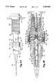
- FIG. 1is a side view, partially broken away, of a gas injection system according to present invention mounted within a vacuum chamber;
- FIG. 2is a cross sectional view taken at II--II in FIG. 1;
- FIG. 3is a cross sectional view taken at III--III in FIG. 1;
- FIG. 4Ais a side view, partially broken away, of a gas injector in accordance with a preferred embodiment of the present invention.
- FIG. 4Bis a longitudinal cross section, partially broken away, of the gas injector in accordance with the preferred embodiment.
- FIG. 5is a longitudinal cross section, partially broken away, of a gas injector according to an alternative embodiment of the present invention.
- the gas injection means 10 in accordance with the present inventionis mounted within an evacuated envelope or vacuum chamber 12 and is utilized for directing reactive gas toward a sample 14 (e.g. a semiconductor device) mounted on stage 16.
- a sample 14e.g. a semiconductor device mounted on stage 16.
- An ion beam 18 generated by means not shownis deflected in a pattern over an area of sample 14 where material is to be removed.
- the entire injection means 10is positioned or aimed via a mechanism located within a bellows 20 that is sealingly attached at its upper end to the wall of evacuated envelope 12.
- the injection meanscomprises a crucible 22 within which a substance to be vaporized is received, the lower end of the crucible being provided with a nozzle member 24 in the form of a hypodermic needle having a small orifice for directing gas toward sample 14.
- the hypodermic needleis attached to the threaded lower end of crucible 22 by lock fitting 50.
- Upper flange 26 of crucible 22is secured to the periphery of sealing chamber 28, the latter depending ultimately from support tube 30.
- Support tube 30is attached with screws 32 to the lower end of bellows 20 as well as to the positioning mechanism (not shown) within the bellows.
- crucible 22comprises a solid metal block elongated in a direction longitudinal of hypodermic needle 24 and provided with a central cylindrical passage 34 through which gas passes to the hypodermic needle.
- the longitudinal passage 34narrows at 36, forming a shoulder for receiving O-ring valve seal 38 that cooperates with the tapered end of valve plunger 40 for regulating the flow of gas from passage 34 to nozzle 24.
- Plunger 40is located at the lower end of actuator 48, the latter comprising a rod disposed coaxially within passage 34 and extending back through the passage.
- the outer diameter of actuator 48is less than the inside diameter of passage 34 in order to form a channel for the delivery of gas.
- central passage 34 in crucible 22there are disposed a plurality of elongated cylindrical chambers 42 parallel to and in substantially surrounding relation with cylindrical passage 34, each chamber 42 comprising a longitudinal bore in the crucible block 22 adapted to receive vaporizable material, such as iodine crystals 44.
- the upper end 46 of the crucibleis open to a sealing chamber 28 wherein gas generated within the crucible chamber is communicated to central passage 34.
- Chamber 28is formed in part within generally cylindrical sealing member or ring 52 to which crucible flange 26 is held via a plurality of socket head screws 54.
- An O-ring seal 56is provided between members 26 and 52 in a slot 57 formed between the two members.
- radial flange 58 of a stepped, cylindrical heat sink member 60is also joined to sealing member 52 with a further plurality of socket head screws 62.
- screws 54 and 62are shown in substantially aligned relation in FIG. 4B for purposes of drawing clarity, the screws are disposed in staggered relation about the periphery of the device as illustrated in FIG. 1 for engaging alternate threaded apertures in sealing member 52.
- Socket head screws 62additionally attach radial flange 64 of support tube 30 by means of which the entire gas injector device is joined to appropriate positioning mechanism as hereinbefore indicated.
- An O-ring sealis located between the flanges 58 and 64.
- a cylindrical spacer ring 70adapted to separate flexible, relatively flat rubber disk shaped membranes 72 and 74, wherein membrane 72 defines the upper wall of sealing chamber 28 and membrane 74 is positioned for defining a region 76 between the two membranes which is vented to the vacuum chamber as hereinafter discussed.
- the periphery or margin of membrane 72is clamped in sealing relation between a side of spacer ring 70 and interior shoulder 80 of sealing member 52, while the periphery or margin of membrane 74 is disposed between the opposite side of spacer ring 70 and land 82 at the lower end of heat sink 60. Screws 62 are drawn up tightly to sealingly clamp the peripheral edges of the membranes 72 and 74 in place.
- Actuator 48includes a radial flange 84 within chamber 28 for centrally engaging membrane 72, while portion 86 of the actuator passes through a central aperture in membrane 72 and into a recess at the lower end of a center membrane spacer 88. Actuator 48 has a threaded portion 90 adapted to engage a mating thread in center membrane spacer 88.
- Center membrane spacer 88is provided at its lower end with a disk shaped head 92 having spaced sides for tightly engaging the central portions of membranes 72 and 74. As threaded portion 90 is drawn up, membrane 72 is sealingly engaged between head 92 and flange 84, with the actuator passing through the membrane.
- center membrane spacer 88is provided with an upper threaded portion 94 mating with internal threads of actuator support tube 96 disposed in surrounding relation to spacer 88 for tightly engaging membrane 74 at the lower end of support tube 96 as the support tube is drawn up tightly on threaded portion 94.
- Tube 96is slideable within recess 106 in heat sink 60 and is attached via internal threads 98 to the lower end of actuating rod 100.
- Rod 100is adapted to receive linear motion under the control of means within the positioning mechanism inside bellows 20 in FIG. 1 or therebeyond.
- Upper cavity 102 in heat sink 60houses a spring 104 acting between the heat sink and the upper end of center membrane spacer 88 so that the membrane spacer and attached parts including support tube 96 and actuator 48 are normally biased in a direction for closing plunger 40 against O-ring 38 to close off the flow of gas.
- rod 100is pulled upwardly (by means not shown) the valve is opened as support tube 96 slides within lower recess 106 in heat sink 60.
- the membranes 72 and 74flex with movement of the actuator.
- Upper end portion 108 of heat sink 60is of reduced cylindrical diameter and receives therearound a band heater 109 provided electrical current by means not shown, the heater being covered and held in place by shrink band 110.
- a thermistor 112is embedded within portion 108 of the heat sink, and when electrical current is supplied to band heater 109, the thermistor 112 provides feedback to a control circuit for regulating the temperature of the heat sink at a desired elevated level for heating the crucible 22 and the material therewithin.
- the heater and control thereforare conveniently located outside the vacuum region of chamber 12 eliminating electrical feedthroughs, but the heat generated is conducted via the vacuum wall (through the heat sink and sealing member 52) to the crucible.
- the solid construction of the crucible 22 provided with bores for receiving crystals 44provides excellent heat transfer and also maintains the temperature in passage 34 to nozzle 24. Moreover, the location of the crystals 44 in chambers 42 at the nozzle end of the device provides a short path for the generated gas and avoids unwanted condensation within or close to the end of the device.
- the gas injection systemforms a housing providing an enclosure for generating and containing gas therewithin.
- this enclosureincludes chambers 42 and central passage 34 of crucible 22 as well as sealing chamber 28 surrounded by the lower end of sealing member 80.
- the gas tight enclosureadditionally comprises the flexible rubber membrane 72 clamped between sealing member 80 and spacer ring 70 at the periphery thereof, while also being centrally clamped in sealing relation to actuator 48 between actuator flange 84 and the head 92 of spacer 88.
- Spacer ring 70includes a plurality of radial passages 114 which extend outwardly from region 76 between membranes 72 and 74 and provide venting into the vacuum chamber via further radial passages 116 formed by the lower castellated shape of heat sink 60. (See FIG. 3.)
- head 92 of center spacer member 88also includes radial passages 118 that communicate with interior bores of the central spacer member 88.
- Membrane 74separates the region 76 from atmospheric pressure present within support tube 30.
- a double barrieris provided between the region where corrosive gas is generated and the external atmosphere outside the vacuum chamber, the corrosive gas generation being totally enclosed within the vacuum chamber, i.e., surrounded on all sides by the vacuum chamber, such that any malfunction of or leak with respect to membrane 72 will leak gas only into the vacuum chamber and will be evacuated therefrom.
- membrane 74were to become punctured, while membrane 72 remained intact, the vacuum chamber would receive air through the puncture without outgassing volatilizable material to the atmosphere.
- the venting of region 76 behind membrane 72 to the vacuum chamberrelieves pressure on membrane 72 and enhances easy flexure thereof, while passages 114 avoid any "virtual leak" from region 76 into the vacuum chamber.
- the gas generation apparatusis totally isolated within the vacuum chamber, without requiring a sliding seal or the like to allow the valve actuator to be operated externally. A superior seal is formed while the corrosive effect of the gas on a sliding actuator seal is avoided.
- the metal partsare for the most part formed of molybdenum including crucible 22, sealing member 52, ring 114, central spacing member 88, tube 96 and lock fitting 50.
- another corrosive resistant materialsuch as titanium can be used.
- Heat sink 60is preferably copper.
- the disk shaped, flexible membranes 72 and 74 in the particular embodimentwere formed of fluorocarbon elastomer marketed under the name Viton (formulation V-884-75) by Parker Seal Group of Lexington, Ky., this material being resistant to corrosive attack. These membranes were 0.075 inches thick and each had a diameter of one inch.
- the device according to the present inventionis employed for supplying a stream of gas directed at a sample being irradiated by an ion beam.
- the lower vacuum chamberis opened and crucible 22 is removed from sealing member 52 by removing socket head screws 54.
- the substance from which gas is to be generatede.g. the iodine crystals 44, is placed within chambers 42 of crucible 22, and the crucible is reattached to the rest of the structure so as to assume an attitude generally depicted in FIG. 1.
- the sample 14is placed on stage 16 and the chamber 12 may be closed and evacuated before the positioning mechanism is employed for directing nozzle 24 toward the location where ion beam 18 is to impinge the sample.
- the crucibleis heated in response to supply of current to heater 108, and the temperature is regulated so that gas is generated, while actuator rod 100 is withdrawn from outside the apparatus to open and regulate the position of valve plunger 40.
- FIG. 5An alternative embodiment according to the present invention is depicted in FIG. 5 wherein corresponding parts are designated by like reference numerals.
- This embodimentdiffers primarily in that only one flexible rubber membrane 72 is utilized between sealing chamber 28 and region 76' beyond membrane 72.
- a metal bellows 124separates region 76' above membrane 72 from atmospheric pressure within support tube 30.
- the bellows 124extends between rings 120 and 126, the former being locked between spacer ring member 70' and heat sink 60', while the latter is secured to the upper end of center rod extension 8' proximate the end of cavity 134 of sink 60' within which it slides as rod 100 is moved against the bias of spring 104 to open and close the valve comprising plunger 40 and O-ring 38.
- Ring 120is held between lower flange 121 of heat sink 60' and the inward part of ring member 70', with O-ring seal 122 disposed therebetween in a slot in member 70'.
- Radial flange 121is held between member 70' and the end flange of support tube 30.
- Member 70'sealingly clamps membrane 72 against sealing ring 52 as screws 132 are drawn up.
- Center rod extension 88'is threadably engaged at 90 by the end of actuator 48 whereby the center of membrane 72 is sealingly disposed between flange 84 and head 92' of center rod extension 88'.
- Ring member 70'is supplied with outwardly extending passages 128 which vent region 70' beyond membrane 72 to the vacuum within vacuum chamber 12 so that the gas generating region is totally enclosed within the vacuum environment. It will be noted that evacuated region 76' is located partly within the bellows 124.
- the ring member 70'extends to the periphery of the device and screws 132 which secure ring 52 to the device support tube 30 pass through member 70'.
- screws 132are shown short in FIG. 5 to reveal vent passages 128, it should be noted that every other screw 132 about the periphery of the device extends to threadably engage sealing ring member 52 for urging member 70' in sealing relation against the periphery of membrane 72.
- the bellows 124is usable in the FIG. 5 embodiment inasmuch as it does not come into direct contact with corrosive vapor.
Landscapes
- Chemical & Material Sciences (AREA)
- Analytical Chemistry (AREA)
- Physics & Mathematics (AREA)
- Engineering & Computer Science (AREA)
- Plasma & Fusion (AREA)
- Physical Vapour Deposition (AREA)
Abstract
Description
Claims (28)
Priority Applications (1)
| Application Number | Priority Date | Filing Date | Title |
|---|---|---|---|
| US08/123,292US5435850A (en) | 1993-09-17 | 1993-09-17 | Gas injection system |
Applications Claiming Priority (1)
| Application Number | Priority Date | Filing Date | Title |
|---|---|---|---|
| US08/123,292US5435850A (en) | 1993-09-17 | 1993-09-17 | Gas injection system |
Publications (1)
| Publication Number | Publication Date |
|---|---|
| US5435850Atrue US5435850A (en) | 1995-07-25 |
Family
ID=22407814
Family Applications (1)
| Application Number | Title | Priority Date | Filing Date |
|---|---|---|---|
| US08/123,292Expired - LifetimeUS5435850A (en) | 1993-09-17 | 1993-09-17 | Gas injection system |
Country Status (1)
| Country | Link |
|---|---|
| US (1) | US5435850A (en) |
Cited By (80)
| Publication number | Priority date | Publication date | Assignee | Title |
|---|---|---|---|---|
| US5603771A (en)* | 1992-09-24 | 1997-02-18 | Office National D'etudes Et De Recherches Aerospatiales | Chemical vapor deposition apparatus activated by a microwave plasma |
| US6036783A (en)* | 1996-04-05 | 2000-03-14 | Ebara Corporation | Liquid material vaporizer apparatus and gas ejection device |
| US6288393B1 (en) | 1998-01-28 | 2001-09-11 | Chipworks | Automated method of circuit analysis |
| US6414307B1 (en) | 1999-07-09 | 2002-07-02 | Fei Company | Method and apparatus for enhancing yield of secondary ions |
| US20030047691A1 (en)* | 2001-07-27 | 2003-03-13 | Musil Christian R. | Electron beam processing |
| US6576913B2 (en)* | 2001-05-17 | 2003-06-10 | Seiko Instruments Inc. | Focused ion beam apparatus having a gas injector in which one of a plurality of nozzles can be selectively driven for elevation |
| US20030185967A1 (en)* | 2002-03-27 | 2003-10-02 | Eby Raymond K. | Method and apparatus for aligning patterns on a substrate |
| US6641705B2 (en) | 2000-03-10 | 2003-11-04 | Fei Company | Apparatus and method for reducing differential sputter rates |
| US20040065826A1 (en)* | 2000-02-25 | 2004-04-08 | Steve Berger | System for imaging a cross-section of a substrate |
| US20040099636A1 (en)* | 2002-11-21 | 2004-05-27 | Lawrence Scipioni | Fabrication of three dimensional structures |
| US20040140438A1 (en)* | 2001-01-19 | 2004-07-22 | Gerlach Robert L. | Angular aperture shaped beam system and method |
| US20040178355A1 (en)* | 2003-03-13 | 2004-09-16 | Jorgen Rasmussen | Sample manipulation system |
| US6797969B2 (en) | 2000-02-09 | 2004-09-28 | Fei Company | Multi-column FIB for nanofabrication applications |
| US20040203249A1 (en)* | 2003-04-02 | 2004-10-14 | Huynh Chuong T. | Dummy copper deprocessing |
| US20040226814A1 (en)* | 2003-01-16 | 2004-11-18 | Stewart Diane K. | Electron beam processing for mask repair |
| EP1479091A2 (en)* | 2002-02-25 | 2004-11-24 | LEO Elektronenmikroskopie GmbH | Material treating system, material treating method and corresponding gas supply |
| US6838380B2 (en) | 2001-01-26 | 2005-01-04 | Fei Company | Fabrication of high resistivity structures using focused ion beams |
| US20050103272A1 (en)* | 2002-02-25 | 2005-05-19 | Leo Elektronenmikroskopie Gmbh | Material processing system and method |
| US20050173631A1 (en)* | 2004-02-11 | 2005-08-11 | Valery Ray | Determining end points during charged particle beam processing |
| US6949756B2 (en) | 2000-01-21 | 2005-09-27 | Fei Company | Shaped and low density focused ion beams |
| US20060186336A1 (en)* | 2005-02-23 | 2006-08-24 | Fei Company | Repetitive circumferential milling for sample preparation |
| JP2006293361A (en)* | 2005-04-08 | 2006-10-26 | Fei Co | Beam induced etching |
| EP1746386A2 (en) | 2005-07-19 | 2007-01-24 | FEI Company | Method of measuring three-dimensional surface roughness of a structure |
| US20070272854A1 (en)* | 2006-05-25 | 2007-11-29 | Enrique Agorio | Sample Preparation |
| US20080073535A1 (en)* | 2006-06-23 | 2008-03-27 | Liang Hong | Planar view sample preparation |
| US20080073587A1 (en)* | 2006-02-15 | 2008-03-27 | Fei Company | Sputtering coating of protective layer for charged particle beam processing |
| US20080088831A1 (en)* | 2006-08-16 | 2008-04-17 | Fei Company | Method for obtaining images from slices of specimen |
| US20080107826A1 (en)* | 2005-01-04 | 2008-05-08 | Instrument Technology Research Center | Method and apparatus for fabricating nanostructure multi-element compound |
| US20080142735A1 (en)* | 2006-10-31 | 2008-06-19 | Fei Company | Charged-particle-beam processing using a cluster source |
| EP1998356A2 (en) | 2007-06-01 | 2008-12-03 | FEI Company | In-Situ STEM Sample Preparation |
| EP2068160A2 (en) | 2007-12-06 | 2009-06-10 | FEI Company | Apparatus and method for observing defects in semiconductor wafers |
| US20090152459A1 (en)* | 2007-11-13 | 2009-06-18 | Carl Zeiss Nts Gmbh | System and Method for Processing an Object |
| US20090154908A1 (en)* | 2007-12-12 | 2009-06-18 | George Engle | Delivery of Iodine Gas |
| US20090220130A1 (en)* | 2005-12-22 | 2009-09-03 | Fei Company | Method for localizing labels in a sample |
| US20100024730A1 (en)* | 2008-02-18 | 2010-02-04 | Emmerich Bertagnolli | Processing system |
| US20100108506A1 (en)* | 2003-11-18 | 2010-05-06 | Fei Company | Method and apparatus for controlling topographical variation on a milled cross-section of a structure |
| EP2214200A2 (en) | 2009-01-30 | 2010-08-04 | Fei Company | High Selectivity, Low Damage Electron-Beam Delineation Etch |
| US20110114665A1 (en)* | 2009-11-16 | 2011-05-19 | Fei Company | Gas delivery for beam processing systems |
| EP2372337A2 (en) | 2010-03-31 | 2011-10-05 | FEI Company | Automated Slice Milling for Viewing a Feature |
| WO2013039891A1 (en) | 2011-09-12 | 2013-03-21 | Fei Company | Glancing angle mill |
| WO2013082496A1 (en) | 2011-12-01 | 2013-06-06 | Fei Company | High throughput tem preparation processes and hardware for backside thinning of cross-sectional view lamella |
| US8502172B1 (en) | 2012-06-26 | 2013-08-06 | Fei Company | Three dimensional fiducial |
| EP2626885A1 (en) | 2012-02-13 | 2013-08-14 | FEI Company | Forming a vitrified sample for an electron microscopy |
| EP2642506A1 (en) | 2012-03-21 | 2013-09-25 | Fei Company | Multiple gas injection system |
| EP2665083A2 (en) | 2012-05-17 | 2013-11-20 | Fei Company | Scanning microscope having an adaptive scan |
| WO2013177209A1 (en) | 2012-05-21 | 2013-11-28 | Fei Company | Preparation of lamellae for tem viewing |
| WO2014014446A1 (en) | 2012-07-16 | 2014-01-23 | Fei Company | Endpointing for focused ion beam processing |
| US8642974B2 (en) | 2009-12-30 | 2014-02-04 | Fei Company | Encapsulation of electrodes in solid media for use in conjunction with fluid high voltage isolation |
| WO2014055935A1 (en) | 2012-10-05 | 2014-04-10 | Fei Company | Multidimensional structural access |
| US8754384B1 (en) | 2013-02-08 | 2014-06-17 | Fei Company | Sample preparation stage |
| WO2014106182A1 (en) | 2012-12-31 | 2014-07-03 | Fei Company | Fiducial design for tilted or glancing mill operations with a charged particle beam |
| US8781219B2 (en) | 2008-10-12 | 2014-07-15 | Fei Company | High accuracy beam placement for local area navigation |
| EP2767823A2 (en) | 2013-02-19 | 2014-08-20 | FEI Company | In situ reactivation of fluorescence marker |
| KR101445933B1 (en) | 2012-11-14 | 2014-10-06 | 진원삼 | Platinum plating apparatus |
| US8884248B2 (en) | 2012-02-13 | 2014-11-11 | Fei Company | Forming a vitrified sample for electron microscopy |
| EP2808885A1 (en) | 2013-05-28 | 2014-12-03 | Fei Company | Precursor for planar deprocessing of semiconductor devices using a focused ion beam |
| US8912490B2 (en) | 2011-06-03 | 2014-12-16 | Fei Company | Method for preparing samples for imaging |
| EP2814050A2 (en) | 2013-06-10 | 2014-12-17 | FEI Company | Electron beam-induced etching |
| EP2818844A1 (en) | 2013-06-28 | 2014-12-31 | Fei Company | Plan view sample preparation |
| US20150017753A1 (en)* | 2013-07-09 | 2015-01-15 | Samsung Display Co., Ltd. | Thin film deposition apparatus and manufacturing method of organic light emitting diode display using the same |
| US8987678B2 (en) | 2009-12-30 | 2015-03-24 | Fei Company | Encapsulation of electrodes in solid media |
| US9196451B2 (en) | 2009-12-30 | 2015-11-24 | Fei Company | Plasma source for charged particle beam system |
| US20150348751A1 (en) | 2014-05-30 | 2015-12-03 | Fei Company | Method and apparatus for slice and view sample imaging |
| US9384982B2 (en) | 2012-12-31 | 2016-07-05 | Fei Company | Depositing material into high aspect ratio structures |
| US9412560B2 (en) | 2012-10-05 | 2016-08-09 | Fei Company | Bulk deposition for tilted mill protection |
| US9488554B2 (en) | 2012-10-05 | 2016-11-08 | Fei Company | Method and system for reducing curtaining in charged particle beam sample preparation |
| EP3096343A1 (en) | 2015-05-18 | 2016-11-23 | FEI Company | Electron beam microscope with improved imaging gas and method of use |
| EP3166127A1 (en) | 2015-10-30 | 2017-05-10 | FEI Company | Method for optimizing charged particle beams formed by shaped apertures |
| US9741536B2 (en) | 2012-10-05 | 2017-08-22 | Fei Company | High aspect ratio structure analysis |
| US9818584B2 (en) | 2011-10-19 | 2017-11-14 | Fei Company | Internal split faraday shield for a plasma source |
| US9837246B1 (en) | 2016-07-22 | 2017-12-05 | Fei Company | Reinforced sample for transmission electron microscope |
| US9978586B2 (en) | 2015-11-06 | 2018-05-22 | Fei Company | Method of material deposition |
| US10347463B2 (en) | 2016-12-09 | 2019-07-09 | Fei Company | Enhanced charged particle beam processes for carbon removal |
| US10401265B1 (en) | 2018-03-30 | 2019-09-03 | Micron Technology, Inc. | Methods for acquiring planar view stem images of device structures |
| US10410829B1 (en) | 2018-03-30 | 2019-09-10 | Micron Technology, Inc. | Methods for acquiring planar view stem images of device structures |
| CN110223902A (en)* | 2019-04-23 | 2019-09-10 | 祁金发 | A control device for ion implantation in wafer production |
| US10546719B2 (en) | 2017-06-02 | 2020-01-28 | Fei Company | Face-on, gas-assisted etching for plan-view lamellae preparation |
| EP3637453A1 (en) | 2018-09-29 | 2020-04-15 | FEI Company | Gis welded micromanipulator extensions |
| CN113035674A (en)* | 2021-02-07 | 2021-06-25 | 上海精测半导体技术有限公司 | Multi-gas-source gas injection device |
| US11261527B2 (en) | 2019-08-12 | 2022-03-01 | MEO Engineering Company, Inc. | Method and apparatus for precursor gas injection |
Citations (8)
| Publication number | Priority date | Publication date | Assignee | Title |
|---|---|---|---|---|
| US4203554A (en)* | 1977-03-24 | 1980-05-20 | Maschinenfabrik Peter Zimmer Aktiengesellschaft | Valve-needle mounting for dyestuff applicator |
| US4851097A (en)* | 1986-12-26 | 1989-07-25 | Seiko Instruments Inc. | Apparatus for repairing a pattern film |
| US4874460A (en)* | 1987-11-16 | 1989-10-17 | Seiko Instruments Inc. | Method and apparatus for modifying patterned film |
| US4874459A (en)* | 1988-10-17 | 1989-10-17 | The Regents Of The University Of California | Low damage-producing, anisotropic, chemically enhanced etching method and apparatus |
| US4930439A (en)* | 1984-06-26 | 1990-06-05 | Seiko Instruments Inc. | Mask-repairing device |
| US4976843A (en)* | 1990-02-02 | 1990-12-11 | Micrion Corporation | Particle beam shielding |
| US5188705A (en)* | 1991-04-15 | 1993-02-23 | Fei Company | Method of semiconductor device manufacture |
| US5294057A (en)* | 1992-04-21 | 1994-03-15 | Spraying Systems Co. | Solenoid operated liquid spray gun |
- 1993
- 1993-09-17USUS08/123,292patent/US5435850A/ennot_activeExpired - Lifetime
Patent Citations (8)
| Publication number | Priority date | Publication date | Assignee | Title |
|---|---|---|---|---|
| US4203554A (en)* | 1977-03-24 | 1980-05-20 | Maschinenfabrik Peter Zimmer Aktiengesellschaft | Valve-needle mounting for dyestuff applicator |
| US4930439A (en)* | 1984-06-26 | 1990-06-05 | Seiko Instruments Inc. | Mask-repairing device |
| US4851097A (en)* | 1986-12-26 | 1989-07-25 | Seiko Instruments Inc. | Apparatus for repairing a pattern film |
| US4874460A (en)* | 1987-11-16 | 1989-10-17 | Seiko Instruments Inc. | Method and apparatus for modifying patterned film |
| US4874459A (en)* | 1988-10-17 | 1989-10-17 | The Regents Of The University Of California | Low damage-producing, anisotropic, chemically enhanced etching method and apparatus |
| US4976843A (en)* | 1990-02-02 | 1990-12-11 | Micrion Corporation | Particle beam shielding |
| US5188705A (en)* | 1991-04-15 | 1993-02-23 | Fei Company | Method of semiconductor device manufacture |
| US5294057A (en)* | 1992-04-21 | 1994-03-15 | Spraying Systems Co. | Solenoid operated liquid spray gun |
Cited By (162)
| Publication number | Priority date | Publication date | Assignee | Title |
|---|---|---|---|---|
| US5603771A (en)* | 1992-09-24 | 1997-02-18 | Office National D'etudes Et De Recherches Aerospatiales | Chemical vapor deposition apparatus activated by a microwave plasma |
| US6036783A (en)* | 1996-04-05 | 2000-03-14 | Ebara Corporation | Liquid material vaporizer apparatus and gas ejection device |
| US6288393B1 (en) | 1998-01-28 | 2001-09-11 | Chipworks | Automated method of circuit analysis |
| US6453063B1 (en) | 1998-01-28 | 2002-09-17 | Chipworks | Automatic focused ion beam imaging system and method |
| US6414307B1 (en) | 1999-07-09 | 2002-07-02 | Fei Company | Method and apparatus for enhancing yield of secondary ions |
| US6949756B2 (en) | 2000-01-21 | 2005-09-27 | Fei Company | Shaped and low density focused ion beams |
| US6797969B2 (en) | 2000-02-09 | 2004-09-28 | Fei Company | Multi-column FIB for nanofabrication applications |
| US6727500B1 (en) | 2000-02-25 | 2004-04-27 | Fei Company | System for imaging a cross-section of a substrate |
| US6838668B2 (en) | 2000-02-25 | 2005-01-04 | Fei Company | System for imaging a cross-section of a substrate |
| US20040065826A1 (en)* | 2000-02-25 | 2004-04-08 | Steve Berger | System for imaging a cross-section of a substrate |
| US6641705B2 (en) | 2000-03-10 | 2003-11-04 | Fei Company | Apparatus and method for reducing differential sputter rates |
| US20040140438A1 (en)* | 2001-01-19 | 2004-07-22 | Gerlach Robert L. | Angular aperture shaped beam system and method |
| US6838380B2 (en) | 2001-01-26 | 2005-01-04 | Fei Company | Fabrication of high resistivity structures using focused ion beams |
| US6576913B2 (en)* | 2001-05-17 | 2003-06-10 | Seiko Instruments Inc. | Focused ion beam apparatus having a gas injector in which one of a plurality of nozzles can be selectively driven for elevation |
| US6753538B2 (en) | 2001-07-27 | 2004-06-22 | Fei Company | Electron beam processing |
| US20030047691A1 (en)* | 2001-07-27 | 2003-03-13 | Musil Christian R. | Electron beam processing |
| EP1892748A2 (en) | 2002-02-25 | 2008-02-27 | Carl Zeiss NTS GmbH | Material processing system and material processing method |
| US20060284090A1 (en)* | 2002-02-25 | 2006-12-21 | Carl Zeiss Nts Gmbh | Material processing system and method |
| US7435973B2 (en) | 2002-02-25 | 2008-10-14 | Carl Zeiss Nts Gmbh | Material processing system and method |
| EP1479091A2 (en)* | 2002-02-25 | 2004-11-24 | LEO Elektronenmikroskopie GmbH | Material treating system, material treating method and corresponding gas supply |
| US20090121132A1 (en)* | 2002-02-25 | 2009-05-14 | Carl Zeiss Nts Gmbh | Material processing system and method |
| US20050103272A1 (en)* | 2002-02-25 | 2005-05-19 | Leo Elektronenmikroskopie Gmbh | Material processing system and method |
| US7868290B2 (en) | 2002-02-25 | 2011-01-11 | Carl Zeiss Nts Gmbh | Material processing system and method |
| US20030185967A1 (en)* | 2002-03-27 | 2003-10-02 | Eby Raymond K. | Method and apparatus for aligning patterns on a substrate |
| US20080147346A1 (en)* | 2002-03-27 | 2008-06-19 | Nanolnk, Inc. | Method and apparatus for aligning patterns on a substrate |
| US7279046B2 (en) | 2002-03-27 | 2007-10-09 | Nanoink, Inc. | Method and apparatus for aligning patterns on a substrate |
| US8043652B2 (en) | 2002-03-27 | 2011-10-25 | Nanoink, Inc. | Method and apparatus for aligning patterns on a substrate |
| US20040099636A1 (en)* | 2002-11-21 | 2004-05-27 | Lawrence Scipioni | Fabrication of three dimensional structures |
| US7160475B2 (en) | 2002-11-21 | 2007-01-09 | Fei Company | Fabrication of three dimensional structures |
| US7727681B2 (en) | 2003-01-16 | 2010-06-01 | Fei Company | Electron beam processing for mask repair |
| US20040226814A1 (en)* | 2003-01-16 | 2004-11-18 | Stewart Diane K. | Electron beam processing for mask repair |
| US20040178355A1 (en)* | 2003-03-13 | 2004-09-16 | Jorgen Rasmussen | Sample manipulation system |
| US6927400B2 (en) | 2003-03-13 | 2005-08-09 | Ascend Instruments, Llc | Sample manipulation system |
| US6995380B2 (en) | 2003-03-13 | 2006-02-07 | Ascend Instruments, Llc | End effector for supporting a microsample |
| US20040178372A1 (en)* | 2003-03-13 | 2004-09-16 | Jorgen Rasmussen | End effector for supporting a microsample |
| US6863787B2 (en) | 2003-04-02 | 2005-03-08 | Fei Company | Dummy copper deprocessing |
| US20040203249A1 (en)* | 2003-04-02 | 2004-10-14 | Huynh Chuong T. | Dummy copper deprocessing |
| US8163145B2 (en) | 2003-11-18 | 2012-04-24 | Fei Company | Method and apparatus for controlling topographical variation on a milled cross-section of a structure |
| US9852750B2 (en) | 2003-11-18 | 2017-12-26 | Fei Company | Method and apparatus for controlling topographical variation on a milled cross-section of a structure |
| US20100108506A1 (en)* | 2003-11-18 | 2010-05-06 | Fei Company | Method and apparatus for controlling topographical variation on a milled cross-section of a structure |
| US20050173631A1 (en)* | 2004-02-11 | 2005-08-11 | Valery Ray | Determining end points during charged particle beam processing |
| US20080107826A1 (en)* | 2005-01-04 | 2008-05-08 | Instrument Technology Research Center | Method and apparatus for fabricating nanostructure multi-element compound |
| US20060186336A1 (en)* | 2005-02-23 | 2006-08-24 | Fei Company | Repetitive circumferential milling for sample preparation |
| US7442924B2 (en) | 2005-02-23 | 2008-10-28 | Fei, Company | Repetitive circumferential milling for sample preparation |
| US7670956B2 (en) | 2005-04-08 | 2010-03-02 | Fei Company | Beam-induced etching |
| US9909218B2 (en) | 2005-04-08 | 2018-03-06 | Ecole Polytechnique Federales De Lausanne | Beam-induced etching |
| JP2006293361A (en)* | 2005-04-08 | 2006-10-26 | Fei Co | Beam induced etching |
| US20100203431A1 (en)* | 2005-04-08 | 2010-08-12 | Ecole Polytechnique Federales De Lausanne | Beam-induced etching |
| US20070018099A1 (en)* | 2005-07-19 | 2007-01-25 | Fei Company | Method of measuring three-dimensional surface roughness of a structure |
| EP1746386A2 (en) | 2005-07-19 | 2007-01-24 | FEI Company | Method of measuring three-dimensional surface roughness of a structure |
| US7348556B2 (en) | 2005-07-19 | 2008-03-25 | Fei Company | Method of measuring three-dimensional surface roughness of a structure |
| US20090220130A1 (en)* | 2005-12-22 | 2009-09-03 | Fei Company | Method for localizing labels in a sample |
| US8306291B2 (en) | 2005-12-22 | 2012-11-06 | Fei Company | Method for localizing labels in a sample |
| US7675049B2 (en) | 2006-02-15 | 2010-03-09 | Fei Company | Sputtering coating of protective layer for charged particle beam processing |
| US20080073587A1 (en)* | 2006-02-15 | 2008-03-27 | Fei Company | Sputtering coating of protective layer for charged particle beam processing |
| EP2209047A1 (en) | 2006-02-15 | 2010-07-21 | FEI Company | Deposition of a protective layer by charged particle beam sputtering and processing of the layer by a charged particle beam |
| US7511282B2 (en) | 2006-05-25 | 2009-03-31 | Fei Company | Sample preparation |
| US20070272854A1 (en)* | 2006-05-25 | 2007-11-29 | Enrique Agorio | Sample Preparation |
| US7423263B2 (en) | 2006-06-23 | 2008-09-09 | Fei Company | Planar view sample preparation |
| US20080073535A1 (en)* | 2006-06-23 | 2008-03-27 | Liang Hong | Planar view sample preparation |
| US20080088831A1 (en)* | 2006-08-16 | 2008-04-17 | Fei Company | Method for obtaining images from slices of specimen |
| US8431896B2 (en) | 2006-08-16 | 2013-04-30 | Fei Company | Method for obtaining images from slices of specimen |
| US7977631B2 (en) | 2006-08-16 | 2011-07-12 | Fei Company | Method for obtaining images from slices of specimen |
| US20110226819A1 (en)* | 2006-08-16 | 2011-09-22 | Fei Company | Method for obtaining images from slices of specimen |
| US20080142735A1 (en)* | 2006-10-31 | 2008-06-19 | Fei Company | Charged-particle-beam processing using a cluster source |
| US8835880B2 (en) | 2006-10-31 | 2014-09-16 | Fei Company | Charged particle-beam processing using a cluster source |
| EP1998356A2 (en) | 2007-06-01 | 2008-12-03 | FEI Company | In-Situ STEM Sample Preparation |
| US8835845B2 (en) | 2007-06-01 | 2014-09-16 | Fei Company | In-situ STEM sample preparation |
| US20090152459A1 (en)* | 2007-11-13 | 2009-06-18 | Carl Zeiss Nts Gmbh | System and Method for Processing an Object |
| US7923702B2 (en) | 2007-11-13 | 2011-04-12 | Carl Zeiss Nts Gmbh | System and method for processing an object |
| US7858936B2 (en) | 2007-12-06 | 2010-12-28 | Fei Company | Slice and view with decoration |
| US20090242759A1 (en)* | 2007-12-06 | 2009-10-01 | Fei Company | Slice and view with decoration |
| EP2068160A2 (en) | 2007-12-06 | 2009-06-10 | FEI Company | Apparatus and method for observing defects in semiconductor wafers |
| US8195039B2 (en)* | 2007-12-12 | 2012-06-05 | Advanced Integration, Inc. | Delivery of iodine gas |
| US20120216874A1 (en)* | 2007-12-12 | 2012-08-30 | George Engle | Delivery of Iodine Gas |
| US8731383B2 (en)* | 2007-12-12 | 2014-05-20 | George M. Engle | Delivery of iodine gas |
| US20090154908A1 (en)* | 2007-12-12 | 2009-06-18 | George Engle | Delivery of Iodine Gas |
| US20100024730A1 (en)* | 2008-02-18 | 2010-02-04 | Emmerich Bertagnolli | Processing system |
| US8939108B2 (en) | 2008-02-18 | 2015-01-27 | Carl Zeiss Microscopy Gmbh | Processing system |
| US8781219B2 (en) | 2008-10-12 | 2014-07-15 | Fei Company | High accuracy beam placement for local area navigation |
| US9087366B2 (en) | 2008-10-12 | 2015-07-21 | Fei Company | High accuracy beam placement for local area navigation |
| US20100197142A1 (en)* | 2009-01-30 | 2010-08-05 | Fei Company | High selectivity, low damage electron-beam delineation etch |
| EP2214200A2 (en) | 2009-01-30 | 2010-08-04 | Fei Company | High Selectivity, Low Damage Electron-Beam Delineation Etch |
| US8778804B2 (en) | 2009-01-30 | 2014-07-15 | Fei Company | High selectivity, low damage electron-beam delineation etch |
| US9150961B2 (en) | 2009-11-16 | 2015-10-06 | Fei Company | Gas delivery for beam processing systems |
| US20110114665A1 (en)* | 2009-11-16 | 2011-05-19 | Fei Company | Gas delivery for beam processing systems |
| US9196451B2 (en) | 2009-12-30 | 2015-11-24 | Fei Company | Plasma source for charged particle beam system |
| US8642974B2 (en) | 2009-12-30 | 2014-02-04 | Fei Company | Encapsulation of electrodes in solid media for use in conjunction with fluid high voltage isolation |
| US8987678B2 (en) | 2009-12-30 | 2015-03-24 | Fei Company | Encapsulation of electrodes in solid media |
| US9412559B2 (en) | 2010-03-31 | 2016-08-09 | Fei Company | Automated slice milling for viewing a feature |
| US8759802B2 (en) | 2010-03-31 | 2014-06-24 | Fei Company | Automated slice milling for viewing a feature |
| US8350237B2 (en) | 2010-03-31 | 2013-01-08 | Fei Company | Automated slice milling for viewing a feature |
| EP2372337A2 (en) | 2010-03-31 | 2011-10-05 | FEI Company | Automated Slice Milling for Viewing a Feature |
| US9111720B2 (en) | 2011-06-03 | 2015-08-18 | Fei Company | Method for preparing samples for imaging |
| US8912490B2 (en) | 2011-06-03 | 2014-12-16 | Fei Company | Method for preparing samples for imaging |
| US9591735B2 (en) | 2011-06-21 | 2017-03-07 | Fei Company | High voltage isolation of an inductively coupled plasma ion source with a liquid that is not actively pumped |
| WO2013039891A1 (en) | 2011-09-12 | 2013-03-21 | Fei Company | Glancing angle mill |
| US9941096B2 (en) | 2011-09-12 | 2018-04-10 | Fei Company | Glancing angle mill |
| US9818584B2 (en) | 2011-10-19 | 2017-11-14 | Fei Company | Internal split faraday shield for a plasma source |
| US9653260B2 (en) | 2011-12-01 | 2017-05-16 | Fei Company | High throughput TEM preparation processes and hardware for backside thinning of cross-sectional view lamella |
| US10283317B2 (en) | 2011-12-01 | 2019-05-07 | Fei Company | High throughput TEM preparation processes and hardware for backside thinning of cross-sectional view lamella |
| WO2013082496A1 (en) | 2011-12-01 | 2013-06-06 | Fei Company | High throughput tem preparation processes and hardware for backside thinning of cross-sectional view lamella |
| EP2626885A1 (en) | 2012-02-13 | 2013-08-14 | FEI Company | Forming a vitrified sample for an electron microscopy |
| EP2626886A2 (en) | 2012-02-13 | 2013-08-14 | Fei Company | Forming a vitrified sample for an electron microscopy |
| US8884248B2 (en) | 2012-02-13 | 2014-11-11 | Fei Company | Forming a vitrified sample for electron microscopy |
| US9275823B2 (en) | 2012-03-21 | 2016-03-01 | Fei Company | Multiple gas injection system |
| EP2642506A1 (en) | 2012-03-21 | 2013-09-25 | Fei Company | Multiple gas injection system |
| US9728375B2 (en) | 2012-03-21 | 2017-08-08 | Fei Company | Multiple gas injection system |
| EP2665083A2 (en) | 2012-05-17 | 2013-11-20 | Fei Company | Scanning microscope having an adaptive scan |
| WO2013177209A1 (en) | 2012-05-21 | 2013-11-28 | Fei Company | Preparation of lamellae for tem viewing |
| US10068749B2 (en) | 2012-05-21 | 2018-09-04 | Fei Company | Preparation of lamellae for TEM viewing |
| US8822957B2 (en) | 2012-06-26 | 2014-09-02 | Fei Company | Three dimensional fiducial |
| EP2680296A2 (en) | 2012-06-26 | 2014-01-01 | Fei Company | Three dimensional fiducial |
| US8502172B1 (en) | 2012-06-26 | 2013-08-06 | Fei Company | Three dimensional fiducial |
| US10204762B2 (en) | 2012-07-16 | 2019-02-12 | Fei Company | Endpointing for focused ion beam processing |
| WO2014014446A1 (en) | 2012-07-16 | 2014-01-23 | Fei Company | Endpointing for focused ion beam processing |
| US10529538B2 (en)* | 2012-07-16 | 2020-01-07 | Fei Company | Endpointing for focused ion beam processing |
| US9696372B2 (en) | 2012-10-05 | 2017-07-04 | Fei Company | Multidimensional structural access |
| US9412560B2 (en) | 2012-10-05 | 2016-08-09 | Fei Company | Bulk deposition for tilted mill protection |
| WO2014055935A1 (en) | 2012-10-05 | 2014-04-10 | Fei Company | Multidimensional structural access |
| US9488554B2 (en) | 2012-10-05 | 2016-11-08 | Fei Company | Method and system for reducing curtaining in charged particle beam sample preparation |
| US9741536B2 (en) | 2012-10-05 | 2017-08-22 | Fei Company | High aspect ratio structure analysis |
| KR101445933B1 (en) | 2012-11-14 | 2014-10-06 | 진원삼 | Platinum plating apparatus |
| US9384982B2 (en) | 2012-12-31 | 2016-07-05 | Fei Company | Depositing material into high aspect ratio structures |
| US11315756B2 (en) | 2012-12-31 | 2022-04-26 | Fei Company | Fiducial design for tilted or glancing mill operations with a charged particle beam |
| WO2014106182A1 (en) | 2012-12-31 | 2014-07-03 | Fei Company | Fiducial design for tilted or glancing mill operations with a charged particle beam |
| US10026590B2 (en) | 2012-12-31 | 2018-07-17 | Fei Company | Fiducial design for tilted or glancing mill operations with a charged particle beam |
| US8754384B1 (en) | 2013-02-08 | 2014-06-17 | Fei Company | Sample preparation stage |
| EP2767823A2 (en) | 2013-02-19 | 2014-08-20 | FEI Company | In situ reactivation of fluorescence marker |
| US9761467B2 (en) | 2013-05-28 | 2017-09-12 | Fei Company | Gas injection system with precursor for planar deprocessing of semiconductor devices using a focused ion beam |
| US9064811B2 (en) | 2013-05-28 | 2015-06-23 | Fei Company | Precursor for planar deprocessing of semiconductor devices using a focused ion beam |
| EP2808885A1 (en) | 2013-05-28 | 2014-12-03 | Fei Company | Precursor for planar deprocessing of semiconductor devices using a focused ion beam |
| US9123506B2 (en) | 2013-06-10 | 2015-09-01 | Fei Company | Electron beam-induced etching |
| US10304658B2 (en) | 2013-06-10 | 2019-05-28 | Fei Company | Electron beam-induced etching |
| EP2814050A2 (en) | 2013-06-10 | 2014-12-17 | FEI Company | Electron beam-induced etching |
| US9040908B2 (en) | 2013-06-28 | 2015-05-26 | Fei Company | Plan view sample preparation |
| US9368325B2 (en) | 2013-06-28 | 2016-06-14 | Fei Company | TEM sample preparation |
| EP2818844A1 (en) | 2013-06-28 | 2014-12-31 | Fei Company | Plan view sample preparation |
| US20150017753A1 (en)* | 2013-07-09 | 2015-01-15 | Samsung Display Co., Ltd. | Thin film deposition apparatus and manufacturing method of organic light emitting diode display using the same |
| US20150348751A1 (en) | 2014-05-30 | 2015-12-03 | Fei Company | Method and apparatus for slice and view sample imaging |
| US9218940B1 (en) | 2014-05-30 | 2015-12-22 | Fei Company | Method and apparatus for slice and view sample imaging |
| US9633816B2 (en) | 2015-05-18 | 2017-04-25 | Fei Company | Electron beam microscope with improved imaging gas and method of use |
| EP3096343A1 (en) | 2015-05-18 | 2016-11-23 | FEI Company | Electron beam microscope with improved imaging gas and method of use |
| US9679742B2 (en) | 2015-10-30 | 2017-06-13 | Fei Company | Method for optimizing charged particle beams formed by shaped apertures |
| EP3166127A1 (en) | 2015-10-30 | 2017-05-10 | FEI Company | Method for optimizing charged particle beams formed by shaped apertures |
| US20210118678A1 (en)* | 2015-11-06 | 2021-04-22 | Fei Company | Method of material deposition |
| US11798804B2 (en)* | 2015-11-06 | 2023-10-24 | Fei Company | Method of material deposition |
| US11069523B2 (en) | 2015-11-06 | 2021-07-20 | Fei Company | Method of material deposition |
| US9978586B2 (en) | 2015-11-06 | 2018-05-22 | Fei Company | Method of material deposition |
| US9837246B1 (en) | 2016-07-22 | 2017-12-05 | Fei Company | Reinforced sample for transmission electron microscope |
| US10347463B2 (en) | 2016-12-09 | 2019-07-09 | Fei Company | Enhanced charged particle beam processes for carbon removal |
| US10546719B2 (en) | 2017-06-02 | 2020-01-28 | Fei Company | Face-on, gas-assisted etching for plan-view lamellae preparation |
| US10539489B2 (en) | 2018-03-30 | 2020-01-21 | Micron Technology, Inc. | Methods for acquiring planar view STEM images of device structures |
| US10410829B1 (en) | 2018-03-30 | 2019-09-10 | Micron Technology, Inc. | Methods for acquiring planar view stem images of device structures |
| US10401265B1 (en) | 2018-03-30 | 2019-09-03 | Micron Technology, Inc. | Methods for acquiring planar view stem images of device structures |
| EP3637453A1 (en) | 2018-09-29 | 2020-04-15 | FEI Company | Gis welded micromanipulator extensions |
| CN110223902B (en)* | 2019-04-23 | 2021-04-20 | 安徽新大陆特种涂料有限责任公司 | Control device for ion implantation in wafer production |
| CN110223902A (en)* | 2019-04-23 | 2019-09-10 | 祁金发 | A control device for ion implantation in wafer production |
| US11261527B2 (en) | 2019-08-12 | 2022-03-01 | MEO Engineering Company, Inc. | Method and apparatus for precursor gas injection |
| US12270105B2 (en) | 2019-08-12 | 2025-04-08 | MEO Engineering Company, Inc. | Method and apparatus for precursor gas injection |
| CN113035674A (en)* | 2021-02-07 | 2021-06-25 | 上海精测半导体技术有限公司 | Multi-gas-source gas injection device |
| CN113035674B (en)* | 2021-02-07 | 2024-10-11 | 上海精测半导体技术有限公司 | Multi-gas source gas injection device |
Similar Documents
| Publication | Publication Date | Title |
|---|---|---|
| US5435850A (en) | Gas injection system | |
| US5827786A (en) | Charged particle deposition of electrically insulating films | |
| US9150961B2 (en) | Gas delivery for beam processing systems | |
| US4669660A (en) | Pulse valve | |
| JP4863593B2 (en) | Method and apparatus for increasing secondary ion yield | |
| US7781743B2 (en) | Charged particle beam system and method for evacuation of the system | |
| JP2779026B2 (en) | Enclosed high intensity electron beam source and system | |
| US4224897A (en) | Methods of depositing materials on substrates | |
| JPH0543787B2 (en) | ||
| US6710338B2 (en) | Focused ion beam system | |
| JP4478645B2 (en) | Substrate coating equipment | |
| US4565158A (en) | Evaporator cell for vacuum deposition on substrates | |
| US3124680A (en) | Agent | |
| US20220316062A1 (en) | Method and apparatus for precursor gas injection | |
| US10651005B2 (en) | Innovative source assembly for ion beam production | |
| GB2358955A (en) | Charged particle beam exposure apparatus and Method | |
| US4516052A (en) | Dispenser for ion source | |
| US3446422A (en) | Ultra-high vacuum device | |
| US5093578A (en) | Valve device for a particle beam apparatus | |
| JPH04215240A (en) | Charged particle beam device | |
| US20040045810A1 (en) | Apparatus and method of forming thin film from negatively charged sputtered ions | |
| EP4389929A1 (en) | Apparatus for depositing material layers on a substrate | |
| JPS6176665A (en) | Device for forming film deposited by evaporation | |
| JPH0364454A (en) | Crucible for vapor source | |
| JP4572366B2 (en) | Raw material gas supply method and supply apparatus for gas deposition method |
Legal Events
| Date | Code | Title | Description |
|---|---|---|---|
| AS | Assignment | Owner name:FEI COMPANY, OREGON Free format text:ASSIGNMENT OF ASSIGNORS INTEREST;ASSIGNOR:RASMUSSEN, JORGEN;REEL/FRAME:006701/0699 Effective date:19930914 | |
| STCF | Information on status: patent grant | Free format text:PATENTED CASE | |
| FEPP | Fee payment procedure | Free format text:PAYOR NUMBER ASSIGNED (ORIGINAL EVENT CODE: ASPN); ENTITY STATUS OF PATENT OWNER: LARGE ENTITY Free format text:PAT HLDR NO LONGER CLAIMS SMALL ENT STAT AS SMALL BUSINESS (ORIGINAL EVENT CODE: LSM2); ENTITY STATUS OF PATENT OWNER: LARGE ENTITY | |
| FPAY | Fee payment | Year of fee payment:4 | |
| FEPP | Fee payment procedure | Free format text:PAYER NUMBER DE-ASSIGNED (ORIGINAL EVENT CODE: RMPN); ENTITY STATUS OF PATENT OWNER: LARGE ENTITY Free format text:PAYOR NUMBER ASSIGNED (ORIGINAL EVENT CODE: ASPN); ENTITY STATUS OF PATENT OWNER: LARGE ENTITY | |
| REMI | Maintenance fee reminder mailed | ||
| FPAY | Fee payment | Year of fee payment:8 | |
| SULP | Surcharge for late payment | Year of fee payment:7 | |
| FPAY | Fee payment | Year of fee payment:12 | |
| AS | Assignment | Owner name:JP MORGAN CHASE BANK, N.A. (AS ADMINISTRATIVE AGEN Free format text:SECURITY AGREEMENT;ASSIGNOR:FEI COMPANY;REEL/FRAME:021064/0319 Effective date:20080604 Owner name:J.P. MORGAN EUROPE LIMITED, AS ALTERNATIVE CURRENC Free format text:SECURITY AGREEMENT;ASSIGNOR:FEI COMPANY;REEL/FRAME:021064/0319 Effective date:20080604 | |
| AS | Assignment | Owner name:FEI COMPANY, OREGON Free format text:RELEASE BY SECURED PARTY;ASSIGNORS:JPMORGAN CHASE BANK, N.A.;J.P. MORGAN EUROPE LIMITED;REEL/FRAME:038328/0787 Effective date:20160324 |