US5435314A - Intravascular imaging catheter tip having a dynamic radius - Google Patents
Intravascular imaging catheter tip having a dynamic radiusDownload PDFInfo
- Publication number
- US5435314A US5435314AUS08/218,005US21800594AUS5435314AUS 5435314 AUS5435314 AUS 5435314AUS 21800594 AUS21800594 AUS 21800594AUS 5435314 AUS5435314 AUS 5435314A
- Authority
- US
- United States
- Prior art keywords
- resolution
- transducer
- mirror
- radius
- focal point
- Prior art date
- Legal status (The legal status is an assumption and is not a legal conclusion. Google has not performed a legal analysis and makes no representation as to the accuracy of the status listed.)
- Expired - Fee Related
Links
- 238000003384imaging methodMethods0.000titleclaimsabstractdescription26
- 238000000034methodMethods0.000claimsdescription6
- 230000005684electric fieldEffects0.000claimsdescription3
- 239000000919ceramicSubstances0.000claimsdescription2
- 230000005540biological transmissionEffects0.000claims1
- 239000000523sampleSubstances0.000abstractdescription15
- 230000003902lesionEffects0.000description5
- 210000001367arteryAnatomy0.000description3
- 238000002592echocardiographyMethods0.000description3
- 239000012190activatorSubstances0.000description2
- 239000000654additiveSubstances0.000description2
- 230000000996additive effectEffects0.000description2
- 210000004204blood vesselAnatomy0.000description2
- 210000002808connective tissueAnatomy0.000description2
- 238000006073displacement reactionMethods0.000description2
- 239000000463materialSubstances0.000description2
- 238000010408sweepingMethods0.000description2
- 230000006835compressionEffects0.000description1
- 238000007906compressionMethods0.000description1
- NKZSPGSOXYXWQA-UHFFFAOYSA-Ndioxido(oxo)titanium;lead(2+)Chemical compound[Pb+2].[O-][Ti]([O-])=ONKZSPGSOXYXWQA-UHFFFAOYSA-N0.000description1
- 238000002608intravascular ultrasoundMethods0.000description1
- ZBSCCQXBYNSKPV-UHFFFAOYSA-Noxolead;oxomagnesium;2,4,5-trioxa-1$l^{5},3$l^{5}-diniobabicyclo[1.1.1]pentane 1,3-dioxideChemical compound[Mg]=O.[Pb]=O.[Pb]=O.[Pb]=O.O1[Nb]2(=O)O[Nb]1(=O)O2ZBSCCQXBYNSKPV-UHFFFAOYSA-N0.000description1
Images


Classifications
- A—HUMAN NECESSITIES
- A61—MEDICAL OR VETERINARY SCIENCE; HYGIENE
- A61B—DIAGNOSIS; SURGERY; IDENTIFICATION
- A61B8/00—Diagnosis using ultrasonic, sonic or infrasonic waves
- A61B8/12—Diagnosis using ultrasonic, sonic or infrasonic waves in body cavities or body tracts, e.g. by using catheters
- A—HUMAN NECESSITIES
- A61—MEDICAL OR VETERINARY SCIENCE; HYGIENE
- A61B—DIAGNOSIS; SURGERY; IDENTIFICATION
- A61B8/00—Diagnosis using ultrasonic, sonic or infrasonic waves
- A61B8/44—Constructional features of the ultrasonic, sonic or infrasonic diagnostic device
- A61B8/4444—Constructional features of the ultrasonic, sonic or infrasonic diagnostic device related to the probe
- A61B8/445—Details of catheter construction
- A—HUMAN NECESSITIES
- A61—MEDICAL OR VETERINARY SCIENCE; HYGIENE
- A61B—DIAGNOSIS; SURGERY; IDENTIFICATION
- A61B8/00—Diagnosis using ultrasonic, sonic or infrasonic waves
- A61B8/44—Constructional features of the ultrasonic, sonic or infrasonic diagnostic device
- A61B8/4444—Constructional features of the ultrasonic, sonic or infrasonic diagnostic device related to the probe
- A61B8/4461—Features of the scanning mechanism, e.g. for moving the transducer within the housing of the probe
- G—PHYSICS
- G01—MEASURING; TESTING
- G01N—INVESTIGATING OR ANALYSING MATERIALS BY DETERMINING THEIR CHEMICAL OR PHYSICAL PROPERTIES
- G01N29/00—Investigating or analysing materials by the use of ultrasonic, sonic or infrasonic waves; Visualisation of the interior of objects by transmitting ultrasonic or sonic waves through the object
- G01N29/22—Details, e.g. general constructional or apparatus details
- G01N29/221—Arrangements for directing or focusing the acoustical waves
- G—PHYSICS
- G01—MEASURING; TESTING
- G01S—RADIO DIRECTION-FINDING; RADIO NAVIGATION; DETERMINING DISTANCE OR VELOCITY BY USE OF RADIO WAVES; LOCATING OR PRESENCE-DETECTING BY USE OF THE REFLECTION OR RERADIATION OF RADIO WAVES; ANALOGOUS ARRANGEMENTS USING OTHER WAVES
- G01S15/00—Systems using the reflection or reradiation of acoustic waves, e.g. sonar systems
- G01S15/88—Sonar systems specially adapted for specific applications
- G01S15/89—Sonar systems specially adapted for specific applications for mapping or imaging
- G01S15/8906—Short-range imaging systems; Acoustic microscope systems using pulse-echo techniques
- G01S15/8934—Short-range imaging systems; Acoustic microscope systems using pulse-echo techniques using a dynamic transducer configuration
- G01S15/8938—Short-range imaging systems; Acoustic microscope systems using pulse-echo techniques using a dynamic transducer configuration using transducers mounted for mechanical movement in two dimensions
- G01S15/894—Short-range imaging systems; Acoustic microscope systems using pulse-echo techniques using a dynamic transducer configuration using transducers mounted for mechanical movement in two dimensions by rotation about a single axis
- G01S15/8943—Short-range imaging systems; Acoustic microscope systems using pulse-echo techniques using a dynamic transducer configuration using transducers mounted for mechanical movement in two dimensions by rotation about a single axis co-operating with reflectors
- G—PHYSICS
- G10—MUSICAL INSTRUMENTS; ACOUSTICS
- G10K—SOUND-PRODUCING DEVICES; METHODS OR DEVICES FOR PROTECTING AGAINST, OR FOR DAMPING, NOISE OR OTHER ACOUSTIC WAVES IN GENERAL; ACOUSTICS NOT OTHERWISE PROVIDED FOR
- G10K11/00—Methods or devices for transmitting, conducting or directing sound in general; Methods or devices for protecting against, or for damping, noise or other acoustic waves in general
- G10K11/002—Devices for damping, suppressing, obstructing or conducting sound in acoustic devices
- G—PHYSICS
- G10—MUSICAL INSTRUMENTS; ACOUSTICS
- G10K—SOUND-PRODUCING DEVICES; METHODS OR DEVICES FOR PROTECTING AGAINST, OR FOR DAMPING, NOISE OR OTHER ACOUSTIC WAVES IN GENERAL; ACOUSTICS NOT OTHERWISE PROVIDED FOR
- G10K11/00—Methods or devices for transmitting, conducting or directing sound in general; Methods or devices for protecting against, or for damping, noise or other acoustic waves in general
- G10K11/18—Methods or devices for transmitting, conducting or directing sound
- G10K11/26—Sound-focusing or directing, e.g. scanning
- G10K11/35—Sound-focusing or directing, e.g. scanning using mechanical steering of transducers or their beams
- G10K11/357—Sound-focusing or directing, e.g. scanning using mechanical steering of transducers or their beams by moving a reflector
- G—PHYSICS
- G01—MEASURING; TESTING
- G01N—INVESTIGATING OR ANALYSING MATERIALS BY DETERMINING THEIR CHEMICAL OR PHYSICAL PROPERTIES
- G01N2291/00—Indexing codes associated with group G01N29/00
- G01N2291/02—Indexing codes associated with the analysed material
- G01N2291/024—Mixtures
- G01N2291/02466—Biological material, e.g. blood
- G—PHYSICS
- G01—MEASURING; TESTING
- G01N—INVESTIGATING OR ANALYSING MATERIALS BY DETERMINING THEIR CHEMICAL OR PHYSICAL PROPERTIES
- G01N2291/00—Indexing codes associated with group G01N29/00
- G01N2291/10—Number of transducers
- G01N2291/101—Number of transducers one transducer
- G—PHYSICS
- G01—MEASURING; TESTING
- G01N—INVESTIGATING OR ANALYSING MATERIALS BY DETERMINING THEIR CHEMICAL OR PHYSICAL PROPERTIES
- G01N2291/00—Indexing codes associated with group G01N29/00
- G01N2291/26—Scanned objects
- G01N2291/263—Surfaces
- G01N2291/2634—Surfaces cylindrical from outside
- G—PHYSICS
- G01—MEASURING; TESTING
- G01S—RADIO DIRECTION-FINDING; RADIO NAVIGATION; DETERMINING DISTANCE OR VELOCITY BY USE OF RADIO WAVES; LOCATING OR PRESENCE-DETECTING BY USE OF THE REFLECTION OR RERADIATION OF RADIO WAVES; ANALOGOUS ARRANGEMENTS USING OTHER WAVES
- G01S7/00—Details of systems according to groups G01S13/00, G01S15/00, G01S17/00
- G01S7/52—Details of systems according to groups G01S13/00, G01S15/00, G01S17/00 of systems according to group G01S15/00
- G01S7/52017—Details of systems according to groups G01S13/00, G01S15/00, G01S17/00 of systems according to group G01S15/00 particularly adapted to short-range imaging
- G01S7/52046—Techniques for image enhancement involving transmitter or receiver
- G01S7/52047—Techniques for image enhancement involving transmitter or receiver for elimination of side lobes or of grating lobes; for increasing resolving power
Definitions
- This inventionis directed toward intravascular imaging, particularly towards improving resolution by dynamically varying the effective radius of resolution of a transducer.
- Cross-sectional scanning of arteriesis performed by sweeping an acoustical beam repeatedly though a series of radial positions within a well-defined cross-sectional plane.
- the acoustic beamis swept by either a mechanically rotated acoustic element or electronically switched elements.
- the echoeswhich contain physical information about the surrounding area, are sampled with the resulting values stored as lines in a scan converter memory. Each line corresponds to the radial position of the acoustic beam at the moment the echoes were created.
- the sampled echoeswill be integrated to form a cross-sectional image of the artery.
- the cross-section of the blood vessel and the lesionis displayed on a TV monitor. This image on the monitor, correctly displays the intima, media, adventitia, plaque, and in some cases the structure of the lesion.
- Sweeping the acoustic beamis accomplished by either rotating a transducer or rotating a mirror. If the transducer is rotated, the shaft must be very flexible as it contains all of the electrical wires for the transducer. When the mirror is rotated, the non-moving transducer avoids the necessity of rotating electrical wires. However in each of these methods, the focal length of the acoustic beam is set, which leaves the best resolution at a fixed radius. This fixed radius may not correspond to the region of interest in the blood vessel.
- a catheter imaging probevaries the effective radius of resolution of an acoustic beam by translating the focal point. Varying the effective radius improves the resolution at any point of interest along the arterial walls.
- the focal pointcan be moved by dynamically translating either the transducer or the mirror in a conventional imaging probe.
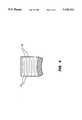
- FIG. 1illustrates a prior art probe.
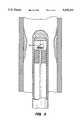
- FIG. 2illustrates a catheter imaging probe according to the present invention.
- FIGS. 3A-Billustrate the operation of the catheter tip 14 shown in FIG. 2.
- FIG. 4illustrates a cross-sectional view of the expanding plug as shown in FIG. 2.
- FIG. 5illustrates a catheter imaging probe where the rotating mirror is shifted along the axis of the flexible shaft.
- FIG. 6illustrates a catheter imaging probe having a radially deflected transducer.
- FIG. 1illustrates a probe of the prior art.
- the probehas a fixed radius of resolution.
- the best image resolutionis along the fixed radius on the intravascular wall.
- FIG. 2illustrates an elegant embodiment of a catheter imaging probe 10 according to the present invention.
- the probeis shown within an artery.
- the radius of resolutioncan be dynamically varied in the catheter imaging probe 10.
- Electrical wires(not shown) are embedded throughout the length of the catheter tube 12.
- a catheter tip 14is housed in the distal end of the catheter tube 12.
- a flexible shaft 16connects to the catheter tip 14, extending through the tube 12 to an external control source (not shown).
- a rotatable mirror 18connects to the flexible shaft 16.
- an expanding plug 20is attached to the distal end of the catheter tube 12 and is connected to the electrical wires (not shown).
- a transducer 22is attached to the expanding plug 20.
- a sleeve bearing 24secures the position of the end of the flexible shaft 16.
- the mirror 18has a fixed linear position with respect to the distal end of the catheter tube 12.
- the transducer 22moves linearly and parallel to the axis of the flexible shaft 16 with respect to the distal end of the catheter tube 12.
- the parallel movement of the transducertranslates the location of the focal point.
- the flexible shaft 16provides rotational movement for the mirror 18.
- suitable shaft rotating technologyhas been described in "Intravascular Ultrasound Imaging", edited by Jonathan Tobis and Paul Yock (1993), and “the Basics of Actuator Technology” by James West in Lasers & Optronics, September 1993. It will be apparent to those versed in the art that the mirror, alternatively, may be translated.
- FIGS. 3A-Billustrates the operation of the catheter tip 14.
- an acoustic beam 26, generated by applying an electrical signal to the transducer 22is brought to a focus at point A.
- the back of the transducer 22is initially a distance c from the mirror. The best resolution is within the adventitia of a lesion.
- FIG. 4illustrates a cross-sectional view of the expanding plug as shown in FIG. 2.
- the expanding plug 20consists of multiple layers of electrorestrictive material 28.
- the electrostrictive layers 28are separated by internal electrodes 30 which are alternately connected.
- the displacementsare additive.
- the displacementis proportional to the square of the number of layers.
- the expanding plugis composed of lead magnesium niobate (PMN) with an additive of lead titanate.
- PMNis a relaxor ferroelectric.
- the properties and applications of relaxor ferroelectrics as actuatorsare described by Uchino et al. in the Journal of Materials Science, volume 16 (1981), pp. 569-578.
- the plughas ten layers of PMN where each layer has a thickness of 0.25 mm is described in that Journal. This provides a total compression of 25 microns when 200 volts are applied to the plug.
- the linear expansionmay also be accomplished by attaching the mirror to an expanding plug. In this case, the PMN plug is powered from the proximal end, through slip rings since the shaft is rotating.
- FIG. 5illustrates a catheter imaging probe where the rotating mirror is shifted along the axis of the flexible shaft.
- the linear expansionmay be accomplished by attaching the mirror to an expanding plug.
- the PMN plugis powered from the proximal end, through slip rings since the shaft is rotating.
- FIG. 6illustrates the catheter imaging probe where the expanding plug is radially deflected.
- the plugis positioned between the transducer and the flexible rotating shaft.
- the position of the transducerchanges with respect to the axis of the flexible rotating shaft.
- the focal lengthremains unchanged, the focal point can be translated from a first radius of resolution to a second radius of resolution.
Landscapes
- Health & Medical Sciences (AREA)
- Physics & Mathematics (AREA)
- Life Sciences & Earth Sciences (AREA)
- Engineering & Computer Science (AREA)
- Acoustics & Sound (AREA)
- General Health & Medical Sciences (AREA)
- Pathology (AREA)
- Public Health (AREA)
- Surgery (AREA)
- Veterinary Medicine (AREA)
- Biophysics (AREA)
- Nuclear Medicine, Radiotherapy & Molecular Imaging (AREA)
- Radar, Positioning & Navigation (AREA)
- Radiology & Medical Imaging (AREA)
- Biomedical Technology (AREA)
- Heart & Thoracic Surgery (AREA)
- Medical Informatics (AREA)
- Molecular Biology (AREA)
- Remote Sensing (AREA)
- Animal Behavior & Ethology (AREA)
- Multimedia (AREA)
- General Physics & Mathematics (AREA)
- Computer Networks & Wireless Communication (AREA)
- Chemical & Material Sciences (AREA)
- Analytical Chemistry (AREA)
- Biochemistry (AREA)
- Immunology (AREA)
- Ultra Sonic Daignosis Equipment (AREA)
Abstract
Description
This invention is directed toward intravascular imaging, particularly towards improving resolution by dynamically varying the effective radius of resolution of a transducer.
Cross-sectional scanning of arteries is performed by sweeping an acoustical beam repeatedly though a series of radial positions within a well-defined cross-sectional plane. The acoustic beam is swept by either a mechanically rotated acoustic element or electronically switched elements. For each radial position, the echoes, which contain physical information about the surrounding area, are sampled with the resulting values stored as lines in a scan converter memory. Each line corresponds to the radial position of the acoustic beam at the moment the echoes were created. Within the scan converter, the sampled echoes will be integrated to form a cross-sectional image of the artery. Using continual imaging techniques, the cross-section of the blood vessel and the lesion is displayed on a TV monitor. This image on the monitor, correctly displays the intima, media, adventitia, plaque, and in some cases the structure of the lesion.
Sweeping the acoustic beam is accomplished by either rotating a transducer or rotating a mirror. If the transducer is rotated, the shaft must be very flexible as it contains all of the electrical wires for the transducer. When the mirror is rotated, the non-moving transducer avoids the necessity of rotating electrical wires. However in each of these methods, the focal length of the acoustic beam is set, which leaves the best resolution at a fixed radius. This fixed radius may not correspond to the region of interest in the blood vessel.
Finer resolution is needed at different radii to better characterize the nature of a lesion. Unfortunately, as the transducer and the mirror are fixed in space, the focal length is also fixed. There are no provisions for dynamically changing the effective radius along the arterial wall. Vital information, which could lead to better treatment, is lost or degraded.
A catheter imaging probe varies the effective radius of resolution of an acoustic beam by translating the focal point. Varying the effective radius improves the resolution at any point of interest along the arterial walls. The focal point can be moved by dynamically translating either the transducer or the mirror in a conventional imaging probe.
FIG. 1 illustrates a prior art probe.
FIG. 2 illustrates a catheter imaging probe according to the present invention.
FIGS. 3A-B illustrate the operation of thecatheter tip 14 shown in FIG. 2.
FIG. 4 illustrates a cross-sectional view of the expanding plug as shown in FIG. 2.
FIG. 5 illustrates a catheter imaging probe where the rotating mirror is shifted along the axis of the flexible shaft.
FIG. 6 illustrates a catheter imaging probe having a radially deflected transducer.
FIG. 1 illustrates a probe of the prior art. The probe has a fixed radius of resolution. The best image resolution is along the fixed radius on the intravascular wall.
FIG. 2 illustrates an elegant embodiment of acatheter imaging probe 10 according to the present invention. The probe is shown within an artery. The radius of resolution can be dynamically varied in thecatheter imaging probe 10. Electrical wires (not shown) are embedded throughout the length of thecatheter tube 12. Acatheter tip 14 is housed in the distal end of thecatheter tube 12. Aflexible shaft 16, connects to thecatheter tip 14, extending through thetube 12 to an external control source (not shown).
At one end of thecatheter tip 14, a rotatable mirror 18 connects to theflexible shaft 16. At the other end, an expandingplug 20 is attached to the distal end of thecatheter tube 12 and is connected to the electrical wires (not shown). Atransducer 22 is attached to the expandingplug 20. A sleeve bearing 24 secures the position of the end of theflexible shaft 16.
Thus, the mirror 18 has a fixed linear position with respect to the distal end of thecatheter tube 12. When an electrical signal is applied to the expandingplug 20, thetransducer 22 moves linearly and parallel to the axis of theflexible shaft 16 with respect to the distal end of thecatheter tube 12. The parallel movement of the transducer translates the location of the focal point. Theflexible shaft 16 provides rotational movement for the mirror 18. An example of suitable shaft rotating technology has been described in "Intravascular Ultrasound Imaging", edited by Jonathan Tobis and Paul Yock (1993), and "the Basics of Actuator Technology" by James West in Lasers & Optronics, September 1993. It will be apparent to those versed in the art that the mirror, alternatively, may be translated.
FIGS. 3A-B illustrates the operation of thecatheter tip 14. In FIG. 3A, anacoustic beam 26, generated by applying an electrical signal to thetransducer 22, is brought to a focus at point A. The back of thetransducer 22 is initially a distance c from the mirror. The best resolution is within the adventitia of a lesion.
In FIG. 3B, the back oftransducer 22 has been translated by an additional distance d. This translation results in a shifted acoustic beam 26'. When the focal point is moved from point A to point B, the best resolution is in the media of the lesion.
FIG. 4 illustrates a cross-sectional view of the expanding plug as shown in FIG. 2. The expandingplug 20 consists of multiple layers ofelectrorestrictive material 28. Theelectrostrictive layers 28 are separated byinternal electrodes 30 which are alternately connected. When an electric field is applied acrosselectrostrictive layers 28, the displacements are additive. The displacement is proportional to the square of the number of layers.
In one embodiment, the expanding plug is composed of lead magnesium niobate (PMN) with an additive of lead titanate. PMN is a relaxor ferroelectric. The properties and applications of relaxor ferroelectrics as actuators are described by Uchino et al. in the Journal of Materials Science, volume 16 (1981), pp. 569-578. The plug has ten layers of PMN where each layer has a thickness of 0.25 mm is described in that Journal. This provides a total compression of 25 microns when 200 volts are applied to the plug. The linear expansion may also be accomplished by attaching the mirror to an expanding plug. In this case, the PMN plug is powered from the proximal end, through slip rings since the shaft is rotating.
Other ways to shift the linear position of the transducer will become apparent to those having ordinary skill in the art. The movement could be provided by alternate means such as a tiny air bellow, a porous plug, an electromechanical activator, or a layered ceramic activator.
FIG. 5 illustrates a catheter imaging probe where the rotating mirror is shifted along the axis of the flexible shaft. The linear expansion may be accomplished by attaching the mirror to an expanding plug. In this case, the PMN plug is powered from the proximal end, through slip rings since the shaft is rotating.
FIG. 6 illustrates the catheter imaging probe where the expanding plug is radially deflected. The plug is positioned between the transducer and the flexible rotating shaft. When a voltage is applied to the plug, the position of the transducer changes with respect to the axis of the flexible rotating shaft. Although the focal length remains unchanged, the focal point can be translated from a first radius of resolution to a second radius of resolution.
Claims (13)
1. An intravascular imaging catheter tip comprising:
catheter housing having a distal end;
a transducer having a focal point that is positioned at a first radius of resolution, the transducer being attached to the distal end of the catheter housing, the transducer emitting a first acoustical wave in response to receiving a first electrical signal and sending a second electrical signal in response to receiving a second acoustical wave;
transmission means for carrying the first and second electrical signals;
a mirror receiving and deflecting the first and second acoustical waves;
rotating shaft that rotates the first and second acoustical waves along a selected radius of resolution; and
translating means, positioned within the distal end of the catheter housing, for shifting the focal point to a second radius of resolution by expanding and contracting.
2. An intravascular imaging catheter tip as defined in claim 1, further comprising:
the translating means being positioned between the transducer and distal end, the translating means shifts the focal point from the first radius of resolution to the second radius of resolution by moving the transducer; and
the rotating shaft being attached to the mirror.
3. An intravascular imaging catheter tip as defined in claim 2, wherein the translating means is a ferroelectric multilayer plug comprising:
a back electrode attached to the distal end of the catheter housing;
a series of ferroelectric layers extending from the back electrode to the transducer;
a plurality of interleaving electrodes, each one interposing two adjacent ferroelectric layers; and
a front electrode connecting between the series and the transducer;
wherein the ferroelectric multilayer plug dynamically shifts the focal point by moving the transducer when an electric field is applied across the back, front and plurality of electrodes.
4. An intravascular imaging catheter tip as defined in claim 2, the translating means comprising a tiny air bellow.
5. An intravascular imaging catheter tip as defined in claim 2, the translating means comprising a porous plug.
6. An intravascular imaging catheter tips defined in claim 2, the translating means comprising an electromechanical actuator.
7. An intravascular imaging catheter tip as defined in claim 2, the translating means comprising a layered ceramic plug.
8. An intravascular imaging catheter tip as defined in claim 1, further comprising the translating means being positioned between the mirror and the rotating shaft, wherein the translating means shifts the focal point from the first radius of resolution to the second radius of resolution by moving the mirror along an axis parallel to the rotating shaft.
9. An intravascular imaging catheter tip as defined in claim 8, wherein the translating means is a ferroelectric multilayer plug comprising:
a back electrode attached to the rotating shaft;
a series of ferroelectric layers extending from the back electrode to the mirror;
a plurality of interleaving electrodes, each one interposing two adjacent ferroelectric layers; and
a front electrode connecting between the series and the mirror;
wherein the ferroelectric multilayer plug dynamically shifts the focal point by moving the mirror when an electric field is applied across the back, front and plurality of electrodes.
10. A method of improving resolution of an intravascular imaging catheter tip having a transducer and a mechanical spring, the method comprising the steps of:
projecting from the transducer an acoustic beam having a focal point at a first radius of resolution along an intravascular wall;
changing the length of the mechanical spring;
translating the focal point to a second radius of resolution along the intravascular wall; and
receiving an image beam.
11. A method of improving resolution as defined in claim 10, wherein the step of translating the focal point comprises moving the transducer.
12. A method of improving resolution as defined in claim 10, wherein:
the step of projecting further comprises projecting the beam onto a mirror; and
the step of translating the focal point comprises moving the mirror linearly.
13. A method of improving resolution as defined in claim 10, wherein the receiving imaging beam is dynamically translated in time.
Priority Applications (1)
| Application Number | Priority Date | Filing Date | Title |
|---|---|---|---|
| US08/218,005US5435314A (en) | 1994-03-25 | 1994-03-25 | Intravascular imaging catheter tip having a dynamic radius |
Applications Claiming Priority (1)
| Application Number | Priority Date | Filing Date | Title |
|---|---|---|---|
| US08/218,005US5435314A (en) | 1994-03-25 | 1994-03-25 | Intravascular imaging catheter tip having a dynamic radius |
Publications (1)
| Publication Number | Publication Date |
|---|---|
| US5435314Atrue US5435314A (en) | 1995-07-25 |
Family
ID=22813382
Family Applications (1)
| Application Number | Title | Priority Date | Filing Date |
|---|---|---|---|
| US08/218,005Expired - Fee RelatedUS5435314A (en) | 1994-03-25 | 1994-03-25 | Intravascular imaging catheter tip having a dynamic radius |
Country Status (1)
| Country | Link |
|---|---|
| US (1) | US5435314A (en) |
Cited By (35)
| Publication number | Priority date | Publication date | Assignee | Title |
|---|---|---|---|---|
| US5596989A (en)* | 1993-12-28 | 1997-01-28 | Olympus Optical Co., Ltd. | Ultrasonic probe |
| WO1997009614A1 (en)* | 1995-09-08 | 1997-03-13 | Framatome | Non destructive control device for the ultrasound controlling of an elongate part |
| US5651772A (en)* | 1996-02-28 | 1997-07-29 | Aeroquip Corporation | Needle guard assembly |
| US5657295A (en)* | 1995-11-29 | 1997-08-12 | Acuson Corporation | Ultrasonic transducer with adjustable elevational aperture and methods for using same |
| US5725503A (en)* | 1996-08-07 | 1998-03-10 | Aeroquip Corporation | Ratcheting needle protector assembly |
| US5807260A (en)* | 1996-07-18 | 1998-09-15 | Ge Yokogawa Medical Systems, Limited | Ultrasound imaging methods and apparatus |
| US5817069A (en)* | 1996-02-28 | 1998-10-06 | Vadus, Inc. | Valve assembly |
| US5842994A (en)* | 1997-07-02 | 1998-12-01 | Boston Scientific Technology, Inc. | Multifunction intraluminal ultrasound catheter having a removable core with maximized transducer aperture |
| US5851196A (en) | 1996-08-07 | 1998-12-22 | Vadus, Inc. | Needle protector |
| US5954698A (en) | 1997-01-08 | 1999-09-21 | Vadus, Inc. | Catheter apparatus having valved catheter hub and needle protector |
| US6080137A (en) | 1997-01-08 | 2000-06-27 | Vadus, Inc. | Needle protector |
| US20020042565A1 (en)* | 1999-08-05 | 2002-04-11 | Cooper Joel D. | Conduits for maintaining openings in tissue |
| US20020111620A1 (en)* | 2001-02-14 | 2002-08-15 | Broncus Technologies, Inc. | Devices and methods for maintaining collateral channels in tissue |
| US20020138074A1 (en)* | 1999-08-05 | 2002-09-26 | Thomas Keast | Devices for applying energy to tissue |
| US20020147412A1 (en)* | 2001-04-05 | 2002-10-10 | Biotronik Mess-Und Therapiegeraete Gmbh & Co. | Electrode line |
| RU2204113C1 (en)* | 2002-03-28 | 2003-05-10 | ЗАО "Нефтегазкомплектсервис" | Carrier of sensors for intrapipe inspection dredger (modifications) |
| US6712812B2 (en) | 1999-08-05 | 2004-03-30 | Broncus Technologies, Inc. | Devices for creating collateral channels |
| US6749606B2 (en) | 1999-08-05 | 2004-06-15 | Thomas Keast | Devices for creating collateral channels |
| US20040151431A1 (en)* | 2003-01-23 | 2004-08-05 | Ljerka Ukrainczyk | Lensed fiber having small form factor and method of making the same |
| US20060229563A1 (en)* | 2005-04-12 | 2006-10-12 | Span-America Medical Systems, Inc. | Passive needle-stick protector |
| US20060276711A1 (en)* | 2005-06-03 | 2006-12-07 | Scimed Life Systems, Inc. | Systems and methods for imaging with deployable imaging devices |
| US7422563B2 (en) | 1999-08-05 | 2008-09-09 | Broncus Technologies, Inc. | Multifunctional tip catheter for applying energy to tissue and detecting the presence of blood flow |
| US7462162B2 (en) | 2001-09-04 | 2008-12-09 | Broncus Technologies, Inc. | Antiproliferative devices for maintaining patency of surgically created channels in a body organ |
| US7708712B2 (en) | 2001-09-04 | 2010-05-04 | Broncus Technologies, Inc. | Methods and devices for maintaining patency of surgically created channels in a body organ |
| US20100168570A1 (en)* | 2008-12-31 | 2010-07-01 | Sliwa John W | Methods and Apparatus for Utilizing Impeller-Based Rotationally-Scanning Catheters |
| US7815590B2 (en) | 1999-08-05 | 2010-10-19 | Broncus Technologies, Inc. | Devices for maintaining patency of surgically created channels in tissue |
| US8002740B2 (en) | 2003-07-18 | 2011-08-23 | Broncus Technologies, Inc. | Devices for maintaining patency of surgically created channels in tissue |
| US8308682B2 (en) | 2003-07-18 | 2012-11-13 | Broncus Medical Inc. | Devices for maintaining patency of surgically created channels in tissue |
| US8409167B2 (en) | 2004-07-19 | 2013-04-02 | Broncus Medical Inc | Devices for delivering substances through an extra-anatomic opening created in an airway |
| US8709034B2 (en) | 2011-05-13 | 2014-04-29 | Broncus Medical Inc. | Methods and devices for diagnosing, monitoring, or treating medical conditions through an opening through an airway wall |
| WO2015158197A1 (en)* | 2014-04-17 | 2015-10-22 | 深圳大学 | Mechanical rotating intravascular ultrasonic probe |
| US9345532B2 (en) | 2011-05-13 | 2016-05-24 | Broncus Medical Inc. | Methods and devices for ablation of tissue |
| JP2019045317A (en)* | 2017-09-01 | 2019-03-22 | 日立Geニュークリア・エナジー株式会社 | Ultrasonic probe, ultrasonic flaw detection apparatus and method |
| US10272260B2 (en) | 2011-11-23 | 2019-04-30 | Broncus Medical Inc. | Methods and devices for diagnosing, monitoring, or treating medical conditions through an opening through an airway wall |
| US11832877B2 (en) | 2017-04-03 | 2023-12-05 | Broncus Medical Inc. | Electrosurgical access sheath |
Citations (3)
| Publication number | Priority date | Publication date | Assignee | Title |
|---|---|---|---|---|
| US5005185A (en)* | 1989-01-19 | 1991-04-02 | Nec Corporation | Parallel mode adaptive transversal equalizer for high-speed digital communications system |
| US5107844A (en)* | 1989-04-06 | 1992-04-28 | Olympus Optical Co., Ltd. | Ultrasonic observing apparatus |
| US5320106A (en)* | 1992-02-20 | 1994-06-14 | Fuji Photo Optical Co., Ltd. | Intracavitary diagnosing apparatus employing ultrasound |
- 1994
- 1994-03-25USUS08/218,005patent/US5435314A/ennot_activeExpired - Fee Related
Patent Citations (3)
| Publication number | Priority date | Publication date | Assignee | Title |
|---|---|---|---|---|
| US5005185A (en)* | 1989-01-19 | 1991-04-02 | Nec Corporation | Parallel mode adaptive transversal equalizer for high-speed digital communications system |
| US5107844A (en)* | 1989-04-06 | 1992-04-28 | Olympus Optical Co., Ltd. | Ultrasonic observing apparatus |
| US5320106A (en)* | 1992-02-20 | 1994-06-14 | Fuji Photo Optical Co., Ltd. | Intracavitary diagnosing apparatus employing ultrasound |
Cited By (58)
| Publication number | Priority date | Publication date | Assignee | Title |
|---|---|---|---|---|
| US5596989A (en)* | 1993-12-28 | 1997-01-28 | Olympus Optical Co., Ltd. | Ultrasonic probe |
| WO1997009614A1 (en)* | 1995-09-08 | 1997-03-13 | Framatome | Non destructive control device for the ultrasound controlling of an elongate part |
| US5657295A (en)* | 1995-11-29 | 1997-08-12 | Acuson Corporation | Ultrasonic transducer with adjustable elevational aperture and methods for using same |
| US5651772A (en)* | 1996-02-28 | 1997-07-29 | Aeroquip Corporation | Needle guard assembly |
| US5817069A (en)* | 1996-02-28 | 1998-10-06 | Vadus, Inc. | Valve assembly |
| US5807260A (en)* | 1996-07-18 | 1998-09-15 | Ge Yokogawa Medical Systems, Limited | Ultrasound imaging methods and apparatus |
| US5725503A (en)* | 1996-08-07 | 1998-03-10 | Aeroquip Corporation | Ratcheting needle protector assembly |
| US5851196A (en) | 1996-08-07 | 1998-12-22 | Vadus, Inc. | Needle protector |
| US5954698A (en) | 1997-01-08 | 1999-09-21 | Vadus, Inc. | Catheter apparatus having valved catheter hub and needle protector |
| US6080137A (en) | 1997-01-08 | 2000-06-27 | Vadus, Inc. | Needle protector |
| US5842994A (en)* | 1997-07-02 | 1998-12-01 | Boston Scientific Technology, Inc. | Multifunction intraluminal ultrasound catheter having a removable core with maximized transducer aperture |
| US6712812B2 (en) | 1999-08-05 | 2004-03-30 | Broncus Technologies, Inc. | Devices for creating collateral channels |
| US20020138074A1 (en)* | 1999-08-05 | 2002-09-26 | Thomas Keast | Devices for applying energy to tissue |
| US20020042565A1 (en)* | 1999-08-05 | 2002-04-11 | Cooper Joel D. | Conduits for maintaining openings in tissue |
| US7815590B2 (en) | 1999-08-05 | 2010-10-19 | Broncus Technologies, Inc. | Devices for maintaining patency of surgically created channels in tissue |
| US6629951B2 (en) | 1999-08-05 | 2003-10-07 | Broncus Technologies, Inc. | Devices for creating collateral in the lungs |
| US6692494B1 (en) | 1999-08-05 | 2004-02-17 | Broncus Technologies, Inc. | Methods and devices for creating collateral channels in the lungs |
| US6749606B2 (en) | 1999-08-05 | 2004-06-15 | Thomas Keast | Devices for creating collateral channels |
| US7422563B2 (en) | 1999-08-05 | 2008-09-09 | Broncus Technologies, Inc. | Multifunctional tip catheter for applying energy to tissue and detecting the presence of blood flow |
| US7022088B2 (en) | 1999-08-05 | 2006-04-04 | Broncus Technologies, Inc. | Devices for applying energy to tissue |
| US7393330B2 (en) | 1999-08-05 | 2008-07-01 | Broncus Technologies, Inc. | Electrosurgical device having hollow tissue cutting member and transducer assembly |
| US20020111620A1 (en)* | 2001-02-14 | 2002-08-15 | Broncus Technologies, Inc. | Devices and methods for maintaining collateral channels in tissue |
| US7175644B2 (en) | 2001-02-14 | 2007-02-13 | Broncus Technologies, Inc. | Devices and methods for maintaining collateral channels in tissue |
| US20070123922A1 (en)* | 2001-02-14 | 2007-05-31 | Broncus Technologies, Inc. | Devices and methods for maintaining collateral channels in tissue |
| US20020147412A1 (en)* | 2001-04-05 | 2002-10-10 | Biotronik Mess-Und Therapiegeraete Gmbh & Co. | Electrode line |
| US7167759B2 (en)* | 2001-04-05 | 2007-01-23 | Biotronik Mess- Und Therapiegeraete Gmbh & Co. Ingenieurbuero Berlin | Electrode line |
| US7462162B2 (en) | 2001-09-04 | 2008-12-09 | Broncus Technologies, Inc. | Antiproliferative devices for maintaining patency of surgically created channels in a body organ |
| US7708712B2 (en) | 2001-09-04 | 2010-05-04 | Broncus Technologies, Inc. | Methods and devices for maintaining patency of surgically created channels in a body organ |
| RU2204113C1 (en)* | 2002-03-28 | 2003-05-10 | ЗАО "Нефтегазкомплектсервис" | Carrier of sensors for intrapipe inspection dredger (modifications) |
| US20040151431A1 (en)* | 2003-01-23 | 2004-08-05 | Ljerka Ukrainczyk | Lensed fiber having small form factor and method of making the same |
| US8002740B2 (en) | 2003-07-18 | 2011-08-23 | Broncus Technologies, Inc. | Devices for maintaining patency of surgically created channels in tissue |
| US9533128B2 (en) | 2003-07-18 | 2017-01-03 | Broncus Medical Inc. | Devices for maintaining patency of surgically created channels in tissue |
| US8308682B2 (en) | 2003-07-18 | 2012-11-13 | Broncus Medical Inc. | Devices for maintaining patency of surgically created channels in tissue |
| US8784400B2 (en) | 2004-07-19 | 2014-07-22 | Broncus Medical Inc. | Devices for delivering substances through an extra-anatomic opening created in an airway |
| US8409167B2 (en) | 2004-07-19 | 2013-04-02 | Broncus Medical Inc | Devices for delivering substances through an extra-anatomic opening created in an airway |
| US8608724B2 (en) | 2004-07-19 | 2013-12-17 | Broncus Medical Inc. | Devices for delivering substances through an extra-anatomic opening created in an airway |
| US11357960B2 (en) | 2004-07-19 | 2022-06-14 | Broncus Medical Inc. | Devices for delivering substances through an extra-anatomic opening created in an airway |
| US10369339B2 (en) | 2004-07-19 | 2019-08-06 | Broncus Medical Inc. | Devices for delivering substances through an extra-anatomic opening created in an airway |
| US7314462B2 (en) | 2005-04-12 | 2008-01-01 | Span-America Medical Systems, Inc. | Passive needle-stick protector |
| US20060229563A1 (en)* | 2005-04-12 | 2006-10-12 | Span-America Medical Systems, Inc. | Passive needle-stick protector |
| US7544166B2 (en) | 2005-06-03 | 2009-06-09 | Scimed Life Systems, Inc. | Systems and methods for imaging with deployable imaging devices |
| US20060276711A1 (en)* | 2005-06-03 | 2006-12-07 | Scimed Life Systems, Inc. | Systems and methods for imaging with deployable imaging devices |
| US9913969B2 (en) | 2006-10-05 | 2018-03-13 | Broncus Medical Inc. | Devices for delivering substances through an extra-anatomic opening created in an airway |
| US20100168570A1 (en)* | 2008-12-31 | 2010-07-01 | Sliwa John W | Methods and Apparatus for Utilizing Impeller-Based Rotationally-Scanning Catheters |
| US9833217B2 (en)* | 2008-12-31 | 2017-12-05 | St. Jude Medical, Atrial Fibrillation Division, Inc. | Methods and apparatus for utilizing impeller-based rotationally-scanning catheters |
| US8932316B2 (en) | 2011-05-13 | 2015-01-13 | Broncus Medical Inc. | Methods and devices for diagnosing, monitoring, or treating medical conditions through an opening through an airway wall |
| US9486229B2 (en) | 2011-05-13 | 2016-11-08 | Broncus Medical Inc. | Methods and devices for excision of tissue |
| US9421070B2 (en) | 2011-05-13 | 2016-08-23 | Broncus Medical Inc. | Methods and devices for diagnosing, monitoring, or treating medical conditions through an opening through an airway wall |
| US9345532B2 (en) | 2011-05-13 | 2016-05-24 | Broncus Medical Inc. | Methods and devices for ablation of tissue |
| US9993306B2 (en) | 2011-05-13 | 2018-06-12 | Broncus Medical Inc. | Methods and devices for diagnosing, monitoring, or treating medical conditions through an opening through an airway wall |
| US10631938B2 (en) | 2011-05-13 | 2020-04-28 | Broncus Medical Inc. | Methods and devices for diagnosing, monitoring, or treating medical conditions through an opening through an airway wall |
| US8709034B2 (en) | 2011-05-13 | 2014-04-29 | Broncus Medical Inc. | Methods and devices for diagnosing, monitoring, or treating medical conditions through an opening through an airway wall |
| US12016640B2 (en) | 2011-05-13 | 2024-06-25 | Broncus Medical Inc. | Methods and devices for diagnosing, monitoring, or treating medical conditions through an opening through an airway wall |
| US10272260B2 (en) | 2011-11-23 | 2019-04-30 | Broncus Medical Inc. | Methods and devices for diagnosing, monitoring, or treating medical conditions through an opening through an airway wall |
| WO2015158197A1 (en)* | 2014-04-17 | 2015-10-22 | 深圳大学 | Mechanical rotating intravascular ultrasonic probe |
| US11832877B2 (en) | 2017-04-03 | 2023-12-05 | Broncus Medical Inc. | Electrosurgical access sheath |
| JP2019045317A (en)* | 2017-09-01 | 2019-03-22 | 日立Geニュークリア・エナジー株式会社 | Ultrasonic probe, ultrasonic flaw detection apparatus and method |
| US11041831B2 (en) | 2017-09-01 | 2021-06-22 | Hitachi-Ge Nuclear Energy, Ltd. | Ultrasonic probe, ultrasonic flaw detection apparatus and method |
Similar Documents
| Publication | Publication Date | Title |
|---|---|---|
| US5435314A (en) | Intravascular imaging catheter tip having a dynamic radius | |
| JP5073276B2 (en) | A rotatable transducer array for volumetric ultrasound | |
| US7892175B2 (en) | Capacitive ultrasonic probe device | |
| US5135001A (en) | Ultrasound sheath for medical diagnostic instruments | |
| US7077808B2 (en) | Ultrasonic imaging catheter | |
| US5505088A (en) | Ultrasound microscope for imaging living tissues | |
| EP1810619B1 (en) | Capacitive ultrasonic transducer and endo cavity ultrasonic diagnosis system using the same | |
| US5429136A (en) | Imaging atherectomy apparatus | |
| CA1304493C (en) | Endoscopically deliverable ultrasound imaging system | |
| US8043222B2 (en) | Transducer with multiple resonant frequencies for an imaging catheter | |
| JP4294376B2 (en) | Ultrasonic diagnostic probe device | |
| US20060173350A1 (en) | Systems and methods for three dimensional imaging with an orientation adjustable array | |
| WO1995002362A9 (en) | Imaging atherectomy apparatus | |
| JPH09522A (en) | Ultrasonic probe and ultrasonic diagnostic equipment | |
| EP0926989A1 (en) | Flexible directive ultrasonically marked catheter | |
| JPH023608B2 (en) | ||
| EP1627603B1 (en) | Ultrasonic endoscope and ultrasonic endoscopic apparatus | |
| JPH0367690B2 (en) | ||
| JPH08173434A (en) | Piezoelectric actuator and ultrasonic probe | |
| JPH0542146A (en) | Ultrasonic probe | |
| Ledworuski et al. | A new ultrasonic catheter system with LIGA geared micromotor | |
| JPH10234736A (en) | Ultrasonic diagnosing device | |
| JP2006204617A (en) | Ultrasonic probe | |
| JPH03106351A (en) | Ultrasonic probe | |
| WO2020183731A1 (en) | Ultrasonic probe |
Legal Events
| Date | Code | Title | Description |
|---|---|---|---|
| AS | Assignment | Owner name:HEWLETT-PACKARD COMPANY, CALIFORNIA Free format text:ASSIGNMENT OF ASSIGNORS INTEREST;ASSIGNOR:DIAS, J. FLEMING;REEL/FRAME:006986/0977 Effective date:19940325 | |
| FEPP | Fee payment procedure | Free format text:PAYOR NUMBER ASSIGNED (ORIGINAL EVENT CODE: ASPN); ENTITY STATUS OF PATENT OWNER: LARGE ENTITY | |
| REMI | Maintenance fee reminder mailed | ||
| LAPS | Lapse for failure to pay maintenance fees | ||
| FP | Lapsed due to failure to pay maintenance fee | Effective date:19990725 | |
| STCH | Information on status: patent discontinuation | Free format text:PATENT EXPIRED DUE TO NONPAYMENT OF MAINTENANCE FEES UNDER 37 CFR 1.362 |