US5434572A - System and method for initiating communications between a controller and a selected subset of multiple transponders in a common RF field - Google Patents
System and method for initiating communications between a controller and a selected subset of multiple transponders in a common RF fieldDownload PDFInfo
- Publication number
- US5434572A US5434572AUS08/255,088US25508894AUS5434572AUS 5434572 AUS5434572 AUS 5434572AUS 25508894 AUS25508894 AUS 25508894AUS 5434572 AUS5434572 AUS 5434572A
- Authority
- US
- United States
- Prior art keywords
- transponders
- bit
- controller
- digital
- transmitting
- Prior art date
- Legal status (The legal status is an assumption and is not a legal conclusion. Google has not performed a legal analysis and makes no representation as to the accuracy of the status listed.)
- Expired - Lifetime
Links
Images


Classifications
- G—PHYSICS
- G06—COMPUTING OR CALCULATING; COUNTING
- G06K—GRAPHICAL DATA READING; PRESENTATION OF DATA; RECORD CARRIERS; HANDLING RECORD CARRIERS
- G06K7/00—Methods or arrangements for sensing record carriers, e.g. for reading patterns
- G06K7/10—Methods or arrangements for sensing record carriers, e.g. for reading patterns by electromagnetic radiation, e.g. optical sensing; by corpuscular radiation
- G06K7/10009—Methods or arrangements for sensing record carriers, e.g. for reading patterns by electromagnetic radiation, e.g. optical sensing; by corpuscular radiation sensing by radiation using wavelengths larger than 0.1 mm, e.g. radio-waves or microwaves
- G06K7/10019—Methods or arrangements for sensing record carriers, e.g. for reading patterns by electromagnetic radiation, e.g. optical sensing; by corpuscular radiation sensing by radiation using wavelengths larger than 0.1 mm, e.g. radio-waves or microwaves resolving collision on the communication channels between simultaneously or concurrently interrogated record carriers.
- G06K7/10029—Methods or arrangements for sensing record carriers, e.g. for reading patterns by electromagnetic radiation, e.g. optical sensing; by corpuscular radiation sensing by radiation using wavelengths larger than 0.1 mm, e.g. radio-waves or microwaves resolving collision on the communication channels between simultaneously or concurrently interrogated record carriers. the collision being resolved in the time domain, e.g. using binary tree search or RFID responses allocated to a random time slot
- G06K7/10039—Methods or arrangements for sensing record carriers, e.g. for reading patterns by electromagnetic radiation, e.g. optical sensing; by corpuscular radiation sensing by radiation using wavelengths larger than 0.1 mm, e.g. radio-waves or microwaves resolving collision on the communication channels between simultaneously or concurrently interrogated record carriers. the collision being resolved in the time domain, e.g. using binary tree search or RFID responses allocated to a random time slot interrogator driven, i.e. synchronous
- G—PHYSICS
- G01—MEASURING; TESTING
- G01S—RADIO DIRECTION-FINDING; RADIO NAVIGATION; DETERMINING DISTANCE OR VELOCITY BY USE OF RADIO WAVES; LOCATING OR PRESENCE-DETECTING BY USE OF THE REFLECTION OR RERADIATION OF RADIO WAVES; ANALOGOUS ARRANGEMENTS USING OTHER WAVES
- G01S13/00—Systems using the reflection or reradiation of radio waves, e.g. radar systems; Analogous systems using reflection or reradiation of waves whose nature or wavelength is irrelevant or unspecified
- G01S13/74—Systems using reradiation of radio waves, e.g. secondary radar systems; Analogous systems
- G01S13/82—Systems using reradiation of radio waves, e.g. secondary radar systems; Analogous systems wherein continuous-type signals are transmitted
- G—PHYSICS
- G06—COMPUTING OR CALCULATING; COUNTING
- G06K—GRAPHICAL DATA READING; PRESENTATION OF DATA; RECORD CARRIERS; HANDLING RECORD CARRIERS
- G06K7/00—Methods or arrangements for sensing record carriers, e.g. for reading patterns
- G06K7/0008—General problems related to the reading of electronic memory record carriers, independent of its reading method, e.g. power transfer
- G—PHYSICS
- G01—MEASURING; TESTING
- G01S—RADIO DIRECTION-FINDING; RADIO NAVIGATION; DETERMINING DISTANCE OR VELOCITY BY USE OF RADIO WAVES; LOCATING OR PRESENCE-DETECTING BY USE OF THE REFLECTION OR RERADIATION OF RADIO WAVES; ANALOGOUS ARRANGEMENTS USING OTHER WAVES
- G01S13/00—Systems using the reflection or reradiation of radio waves, e.g. radar systems; Analogous systems using reflection or reradiation of waves whose nature or wavelength is irrelevant or unspecified
- G01S13/02—Systems using reflection of radio waves, e.g. primary radar systems; Analogous systems
- G01S13/06—Systems determining position data of a target
- G01S13/08—Systems for measuring distance only
- G01S13/32—Systems for measuring distance only using transmission of continuous waves, whether amplitude-, frequency-, or phase-modulated, or unmodulated
- G01S13/325—Systems for measuring distance only using transmission of continuous waves, whether amplitude-, frequency-, or phase-modulated, or unmodulated using transmission of coded signals, e.g. P.S.K. signals
- G—PHYSICS
- G01—MEASURING; TESTING
- G01S—RADIO DIRECTION-FINDING; RADIO NAVIGATION; DETERMINING DISTANCE OR VELOCITY BY USE OF RADIO WAVES; LOCATING OR PRESENCE-DETECTING BY USE OF THE REFLECTION OR RERADIATION OF RADIO WAVES; ANALOGOUS ARRANGEMENTS USING OTHER WAVES
- G01S13/00—Systems using the reflection or reradiation of radio waves, e.g. radar systems; Analogous systems using reflection or reradiation of waves whose nature or wavelength is irrelevant or unspecified
- G01S13/74—Systems using reradiation of radio waves, e.g. secondary radar systems; Analogous systems
- G01S13/82—Systems using reradiation of radio waves, e.g. secondary radar systems; Analogous systems wherein continuous-type signals are transmitted
- G01S13/825—Systems using reradiation of radio waves, e.g. secondary radar systems; Analogous systems wherein continuous-type signals are transmitted with exchange of information between interrogator and responder
Definitions
- the present inventionis related to that described in U.S. patent application Ser. Nos. 08/194,706 entitled “INTEGRATION OF HIGH VALUE CAPACITOR WITH FERROELECTRIC MEMORY” filed on Feb. 10, 1994; and 08/210,699 entitled “SYSTEM AND METHOD FOR WRITE-PROTECTING PREDETERMINED PORTIONS OF A MEMORY ARRAY", filed on Mar. 18, 1994 both assigned to the assignee of the present invention, the disclosures of which are hereby specifically incorporated by this reference.
- the present inventionrelates, in general, to the field of radio frequency (“RF") identification (“ID”) systems. More particularly, the present invention relates to a system and method for initiating communications between a controller and a selected one or other subset of multiple transponders in a common RF field.
- RFradio frequency
- the system and method of the present inventionis of particular utility in conjunction with the Racom RFM256 passive, proximity RF read/write card transponder ("RF/ID Tag”) and an associated RFC100 CORE reader/writer electronics module controller available from Racom Systems, Inc., 6080 Greenwood Plaza Boulevard, Englewood, Colo., 80111 or other similar devices.
- the Racom RFM256is a passive RF transponder incorporating a non-volatile memory element which is powered by inductive coupling to a proximately located RF controller.
- the Racom communication systemutilizes the controller to frequency shift key (“FSK”) the powering RF signal to cause the transponder to either read data from, or write data to, the non-volatile memory and transmit the same back to the controller utilizing phase shift keying (“PSK”) modulation in response to specific commands from the controller.
- FSKfrequency shift key
- PSKphase shift keying
- the Racom communications systemmay operate in either full duplex or half duplex modes with the controller causing the transponder to simultaneously write data to its non-volatile memory array as the contents are read out and transmitted to the controller by complementing selected bits thereof.
- the Racom RFM256 transponderutilizes a ferroelectric random access memory (“FRAM®”) non-volatile integrated circuit memory array manufactured using a proprietary lead-zirconate-titanate (“PZT”) ceramic thin film process and is available from Ramtron International Corporation, Colorado Springs, Colo., the assignee of the present invention.
- FRAM®ferroelectric random access memory
- PZTlead-zirconate-titanate
- the Racom communication systemutilizes FSK modulated RF signals transmitted from the controller to the transponder from which the latter derives it power.
- FSK modulationallows the average signal power to remain at a maximum as opposed to other modulation techniques such as amplitude shift keying ("ASK") or pulse modulation techniques and the transponder is able to demodulate the FSK encoded signal without the incorporation of an on-chip oscillator frequency reference.
- ASKamplitude shift keying
- pulse modulation techniquesthe transponder is able to demodulate the FSK encoded signal without the incorporation of an on-chip oscillator frequency reference.
- a controllermodulates a data signal between 125 KHz and 116.3 KHz to send a four bit time synchronization block, a start bit, memory address and command bits which are operative to cause the transponder to read: a) only the word at such address or b) the entire contents of the memory beginning at such address.
- the RFM256 transponderupon power up by entering the electromagnetic field of the associated controller, continuously transmits a configuration word to the controller utilizing a coherent PSK modulated signal of 62.5 KHz derived from the 125 KHz FSK RF input.
- Each RFM256 transponder configuration wordincludes a sync block and start bit corresponding with those portions of the controller command word as well as the number of bits designating the memory words which have been previously "locked” from further writes by the controller.
- a number of "hard-wired" mask bits and type bitsare utilized to identify a particular transponder, or other subset of multiple transponders, to the controller and distinguish it from others.
- These or other memory locations within the ferroelectric memory arraymay be utilized to establish a unique ID number for a given transponder or a uniquely common ID number for a selected subset of multiple transponders with which the controller may desire to communicate.
- the Racom transponder and communications systemmay be operated in either half duplex or full duplex mode.
- the transponderwill transmit the requested words from memory in response to a "read" command beginning at the words specified in the word address portion of the command word.
- the controllermust first know the contents of the transponder memory before initiating a "write” which operation is effectuated by sending a burst of 116.3 KHz RF power in synchronization with each bit read out of the transponder memory that is desired to complement.
- the controllerwill then initiate another "read” of the relevant portions of the transponder memory to verify that the write operation has been properly effectuated.
- the communication systemmay be operated in full duplex mode whereby the read/write/verify operations are effectuated in a single pass operation.
- the controllerwill complement the selected bits of the memory words as they are read out by the transponder and verify that the data was written properly during each of the single bit times.
- the controlleror "reader” be able to single out a particular transponder, or selected subset of transponders, from among the plurality which may be within the powering RF field of the controller at any time.
- communications between the controller and the particular transponder(s)are rendered more secure by eliminating the possibility that two or more transponders might attempt to communicate with the controller at the same time thereby interfering with each other resulting in the possible corruption of data read or written between the controller and transponder.
- system and method herein disclosedmay be utilized to communicate with a selected subset of multiple transponders each having a uniquely common ID number or ID number portion in those applications in which, for example, it is desired to write data to a selected group of transponders simultaneously.
- This latter embodimenthas particular utility in baggage tag applications wherein all transponders associated with luggage to be directed to a given destination may be written with the same destination information concurrently.
- each transponderhas a unique (or uniquely common) ID number programmed into it in the form of any combination of "mask" bits, "type” bits and/or other selected bits within the non-volatile memory.
- the transponderreceives from the controller a series of commands/questions and either responds or does not respond based on this ID number.
- the transponderresponds to the controller in such a way that, if multiple transponders respond, the controller can recognize that at least one transponder has responded. For individual responses, the controller is not required to determine how many transponders have responded.
- the controllersends a sequence of commands that single out an individual transponder or group of transponders based upon the ID number sought.
- each of the transpondersincludes an n-bit digital address.
- a first subset of the plurality of the transponders having a possible first bit as the first bit of its n-bit digital addresstransmits a signal to the controller in response to a signal from the controller inquiring as to whether or not the transponders have the possible first bit in the first bit position.
- the non-responsively transmitting transpondersalternatively enter a reset state if the first bit of their n-bit digital address is not the possible first bit.
- the controllernext transmits a next digital signal to the responding plurality of transponders representative of a possible next bit of the n-bit digital address of the first subset of the plurality of transponders.
- a second subset of the first subset of transponders having the possible next bit as the next bit of its n-bit digital addressresponsively transmits a signal to the controller and the non-responsively transmitting transponders alternatively enter a reset state.
- the controlleralternatively transmits additional next digital signals to the plurality of transponders representative of possible additional next bits of the n-bit digital address of the responsively transmitting transponders until the digital signals transmitted from the controller to the plurality of transponders representative of the possible first, next and additional next bits of the n-bit address correspond with the first, next and additional next bits of the n-bit address of the selected subset of the plurality of transponders.
- a last digital signalis transmitted from the controller to the plurality of transponders when the selected subset of the plurality of transponders has responsively transmitted a signal to the controller indicative of a predetermined n-bit address of the selected subset of the plurality of transponders.
- a method for initiating communications with a selected subset of a plurality of transponders in a common RF field of a controllerwherein each of the plurality of transponders has an n-bit address.
- the methodcomprises the steps of transmitting a first signal to the plurality of transponders to establish a given logic level of a first bit of the various n-bit addresses, wherein the transponders having the given logic level as the first bit of their n-bit address respond to said controller and the non-responding transponders enter a reset state.
- a next signalis transmitted to the plurality of transponders to establish an opposite logic level of the first bit of their n-bit addresses if none of the transponders respond to the first signal, wherein transponders having the opposite logic level as the first bit of their n-bit address respond to the controller and the non-responding transponders enter a reset state.
- Logic level inquiry signalsare selectively transmitted to the plurality of transponders to establish a logic level of each remaining bit of their n-bit addresses, wherein the transponders having logic levels of the remaining bits of their n-bit address corresponding to the logic level inquiry signals respond to the controller and the non-responding transponders enter a reset state.
- the methodcomprises the steps of transmitting a series of digital signals from the controller to the transponders corresponding to the n-bit address of the selected subset of the plurality of transponders.
- a responseis transmitted to the series of digital signals from the selected subset of the plurality of transponders and the plurality of transponders other than the selected subset of the plurality of transponders enter a reset state.
- a communications systemfor initiating communication between a controller and a selected subset of a plurality of transponders in a common RF field, wherein each of the transponders has a unique, or commonly unique, n-bit address.
- the systemcomprises transmitter means associated with the controller for transmitting a series of digital signals from the controller to the transponders corresponding to the n-bit address of the selected subset of the plurality of transponders.
- Response means associated with each of the plurality of transponderstransmit a response to the series of digital signals if the series of digital signals corresponds to the transponder's n-bit address and reset means associated with each of the plurality of transponders cause the transponder to enter a reset state if the series of digital signals does not correspond to the transponder's n-bit address.
- the principles of the present inventionare applicable to the initiation of communications with a particular individual transponder having a single, unique ID number as well as with a greater selected subset of a plurality of transponders wherein each of the selected subset have a uniquely common ID number or ID number segment. In this manner, identical data may be written to the selected subset of multiple transponders simultaneously.
- FIG. 1is a simplified representational view of a number of passive RF/ID transponders (or “tags”) which have been introduced within the powering electromagnetic field of an associated RF controller (or “reader”) by means of which commands may be directed to a particular one of the transponders based upon its unique address via a 125 KHz FSK modulated signal and the appropriate transponder will respond via a PSK modulated 62.5 KHz signal while the remaining transponders enter a reset state;
- FIG. 2Ais a logic flow diagram of, for example, the firmware of a controller microprocessor for sending predefined commands in a predefined sequence and monitoring responses thereto from a number of transponders in a common RF field which may be utilized for initiating communications with a particular target transponder based upon its unique ID number or address;
- FIG. 2Bis an additional logic flow diagram of, for example, the firmware of a controller microprocessor for sending predefined commands in a specific sequence and monitoring responses thereto from a number of transponders in a common RF field which may be utilized for initiating communications with a specific target transponder or other selected subset of transponders;
- FIG. 3Ais a logic flow diagram for the control logic or finite state machine of a transponder useful in conjunction with the controller logic flow of FIG. 2A or 2B for identifying a particular one of a plurality of transponders based on its unique ID number while simultaneously causing any other transponders within the RF field of the controller to enter a reset state;
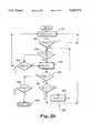
- FIG. 3Bis an additional logic flow diagram for the control logic or finite state machine of a transponder useful for more rapidly identifying a particular one of a plurality of transponders utilizing a single command for each bit in the unique ID number of the transponder.
- transponders 10or “tags” are shown in conjunction with a controller 12, or “reader” comprising a communications system for reading data from and writing data to a selected one of the transponders 10.
- the controller 12comprises a microprocessor 14 for controllably operating an FSK transmit section 16 coupled to an antenna 20.
- the controller 12broadcasts, for example, an FSK modulated 125 KHz signal to the transponders 10 to provide commands to a selected one of the transponders 10 to either read data from, or write data to, the on-board non-volatile memory array.
- the FSK modulated 125 KHz signalmay also be utilized to derive on-board power for the non-volatile memory array and other associated logic blocks of the transponders 10.
- transponder 10In response to a command directed to a specific one of the transponders 10, that particular transponder 10 will respond with configuration data or data stored within the non-volatile memory array by means of, for example, a 62.5 KHz PSK modulated signal.
- This 62.5 KHz signalis received by the antenna 20 and is coupled to the microprocessor 14 by means of a PSK receive section 18.
- controller 12may be coupled to a host computer 22 by means of an RS-232 or Wiegand interface.
- transponder 10If only a single transponder 10 is within the effective range of the FSK modulated signal transmitted from the controller 12, there can be no confusion about which transponder 10 is responding to commands from the controller 12 or attempting to communicate therewith. However, if multiple transponders 10 are in a common RF field of the controller 12, the controller 12 must, in certain applications, be able to single out each transponder 10 individually in order to eliminate the possibility of two transponders 10 attempting to communicate with the controller 12 at the same time thereby interfering with each other's transmissions leading to the possibility of data corruption.
- the transponders 10will each have a unique binary ID number programmed into them. For example, “tag X” has the unique ID number of "010;” “tag Y” has the unique ID number of "011;” and “tag Z” has the unique ID number of "110.” It should also be noted that the unique n-bit address may comprise any number of bits including 8, 16, 32 and the like. In accordance with a process more fully described hereinafter, the transponders 10 receive from the controller 12 a series of commands/questions to which they either respond, or do not respond and then reset themselves.
- the transponders 10respond to the controller 12 in such a way that if multiple transponders 10 happen to respond, the controller 12 can recognize that at least one transponder 10 has responded. For individual responses, the controller 12 is not required to determine how many transponders 10 have responded. Fundamentally, the controller 12 sends a sequence of commands that single out an individual one of the transponders 10 based upon its unique ID number.
- the four commands that the controller 12 may sendare:
- BIT0--thisinquires of all transponders 10 within the RF field as to whether they have a "zero" in the current bit of its unique ID number;
- BIT1--thisinquires of the transponders 10 as to whether they have a "one" as the current bit of its unique ID number;
- FOUND--is a command from the controller 12 to the transponders 10 within the common RF field that the proper one of the transponders 10 has been found.
- the RESET0 commandcorresponds to a "00"; the BIT0 command corresponds to a "01”; the BIT1 command corresponds to a "10” and the FOUND command corresponds to a "11".
- Table 4illustrates the sequence of commands for identifying "tag Y” while Table 7 illustrates the corresponding "RESET0,” “BIT0,” “BIT1,” and “FOUND” commands necessary to identify "tag Z" with all other transponders 10 entering a reset state until the RESET0 command is again transmitted by the controller 12.
- the command from the controller 12may, instead, comprise a three bit command if the response(s) from one or more transponders 10 does not carry with it the possibility of interfering with the command transmitted from the controller 12.
- communications from the controller 12 to the transponders 10is made using an FSK modulation technique while responses from the transponders 10 to the controller 12 are made via a PSK modulated signal.
- the communications from the transponders 10 to the controller 12will not interfere with the commands transmitted from the controller 12.
- a logic flow 100 for effectuating the initiation of communications with a selected one of multiple transponders 10 within a common electric field of a controller 12is shown which identifies a particular one of the transponders 10 in order.
- the logic flow 100begins with a reset step 102 at which a reset count is set equal to zero.
- the controller 12sends a "00" to all transponders 10 within the common RF field.
- the controller 12determines whether or not one or more of the transponders 10 have responded to the RESET0 command. If a response from one or more of the transponders 10 is detected, the logic flow 100 proceeds to increment count step 112 as will be more fully described hereinafter.
- the controller 12 firmwarewould then direct that a "10" be transmitted at send BIT1 step 108. Thereafter, at decision step 110, the controller 12 would determine whether or not a response was detected to the BIT1 command. If a response is not detected, the logic flow 100 returns to reset step 102. Alternatively, if a response is detected to the BIT1 command, then the count is incremented at increment count step 112 by one.
- the controller 12will send a "01" at send BIT0 step 114. Thereafter, the controller 12 will monitor the transponders 10 within the RF field to see whether or not there was a response at decision step 116. If a response is not detected at decision step 116, then the controller 12 will send a "10" at send BIT1 step 118. If a response is detected from a transponder 10 at decision step 116 or decision step 120, then, at terminal count decision step 122 it is determined whether or not the count has equalled a value of "31", or 2 5 -1, which is equal to the number of unique ID bits-1.
- the logic flow 100returns to increment count step 112. If the count value is now equal to "31”, then at send step 124 the command "FOUND” or "11”, will be transmitted to all of the transponders 10 within the RF field and the Found Tag step 126 is reached. If, at decision step 120, a response is not detected from a transponder 10, the logic flow 100 would also return to reset step 102 as shown.
- FIG. 2Ba an additional controller 12 logic flow 101 is illustrated for finding a specific transponder 10 by purposefully seeking out a transponder 10 with a particular n-bit address.
- like steps to those previously described with respect to steps 102 through 110 of FIG. 2Aare like numbered and the foregoing description thereof shall suffice herefor.
- a decision step 113is reached where, if the desired bit is a "1", the process proceeds to step 115 to send a "01". Alternatively, if the desired bit is a "0", then at step 117 a "01" is also transmitted and a decision step 125 is reached. At decision step 125, if no response is received the process returns to step 102 to reset the count to "0". Alternatively, if a response is received, the process proceeds to an additional decision step 127 as will be more fully described hereinafter.
- step 115regardless of the response received from the transponders 10, the controller 12 ignores it and sends a "10" at step 121. Then, at decision step 123, if a response is not received, the process returns to step 102 to reset the count to "0". Alternatively, the process proceeds to decision step 127 where, if the count is not equal to "31", the process returns to step 112 to increment the count by "1". If the count is now equal to "31” then, at step 129 a "11" is transmitted to the transponders 10 and the process concludes at Found Tag step 131.
- Transponder logic flow 130begins with a reset step 132 at which the count value is reset to zero. Thereafter, at decision step 134 a determination is made as to whether a RESET0 command ("00") was received. If the RESET0 command was received, the transponder logic flow 130 proceeds to decision step 136. However, if RESET0 was not received, and one of BIT0 ("01"), BIT1 ("10") or FOUND ("11") was detected instead, then the process returns to reset step 132. At decision step 136, if the value of Bit[count] equals zero, then the transponder logic flow 130 proceeds to respond step 138.
- bit[count]the value of Bit[count] is not equal to zero. If the value of Bit[count] is not equal to zero, then at decision step 146 it is determined whether or not the BIT1 command was received. If the BIT1 command has been received, the transponder logic flow 130 proceeds to responder step 138. Alternatively, if any other command has been received, the transponder logic flow 130 returns to the reset step 132.
- terminal count decision step 140it is determined whether a terminal count of "31" has been reached on the internal counter. If the terminal count has been reached, then the transponder logic flow 130 proceeds to decision step 148 to indicate that the appropriate transponder 10 has been determined at Found Tap step 150, if a "11" has been received If a "00", "01” or “10” has been received instead, decision step 148 is followed by reset step 131. If the terminal count has not been reached at terminal count decision step 140 then at decision step 142, the transponder 10 determines whether the "BIT0" command has been received and, if so, the transponder logic flow 130 then proceeds to increment count step 144 where the count value is increased by one. Alternatively, if a command other than BIT0 command has been received, the transponder logic flow 130 returns to the reset step 132.
- the controller 12initially sends the RESET0 ("00") command resetting all of the transponders 10 within the effective RF field of the controller 12. All of the transponders 10 that have a "0" in the first bit position of their unique ID number respond to the controller 12. The controller 12 will then proceed to undertake two alternative courses of action, based upon whether or not it has received a response to the RESET0 command. If the controller 12 detects a response, it increments an internal counter and sends the BIT0 ("01") command. If, on the other hand, the controller 12 does not detect a response, it sends the BIT1 ("10") command.
- each individual transponder 10Upon reception of the second command, each individual transponder 10 reacts in a manner dependent upon which command is received. If the transponder 10 has a "1" in the first bit position and it receives the BIT0 command, it resets itself. Alternatively, if the transponder 10 has a "1" in the first bit position and it receives the BIT1 command, it responds and increments its internal counter. If the transponder 10 has a "0" in the first bit position and it receives the BIT0 command, it responds if it has a "0" in the second bit of its unique ID number.
- Each transponder 10therefore, responds based on the digital value of its unique ID number and the sequence of commands received from the controller 12. All transponders 10 not receiving the correct sequence of commands will reset themselves during the communication sequence and refrain from responding to further commands from the controller 12 until the command RESET0 is sent. In this manner, only a single transponder 10 will not reset itself during this initial communication. This transponder 10 may then be communicated to without interference from other transponders 10 which may also be in the common RF field. Additionally, if the controller 12 wants to single out a particular transponder 10 with a specific unique ID number, it only need send a specific sequence of commands based on the unique ID number desired and verify that it receives responses at the appropriate times. All other transponders 10 will reset themselves as a result of the commands sent.
- FIG. 3ban alternative logic flow 131 for a transponder 10 is shown which allows for the rapid identification of a given transponder 10.
- the commands previously describedhave been modified to reflect the following: "00” is a reset command; "01” is a command inquiring as to whether or not the current bit is a "0"; “10” is a command inquiring as to whether or not the current bit is a "1”; and "11” is a Found Tag command as before described.
- like steps to those previously described with respect to steps 132 and 134 of the logic flow of FIG. 3Aare like numbered and the foregoing description thereof shall suffice herefor.
- a decision step 135is reached where, if the transponder 10 has received a "01" or "10" command the process proceeds to decision steps 137 or 139 respectively.
- decision steps 137 and 139if the result is not true, the process returns to step 132 and the count is reset to "0".
- step 141if the count is not equal to "31”, the process proceeds to step 143 where the count is incremented by "1" and decision step 135 is repeated. If the count is equal to "31" at decision step 141 then, at decision step 145, if a "00", "01” or “10" has been received the process returns to step 132 to reset the count to "0". On the other hand, if the command received by the transponder 10 is a "11", then the process ends with Found Tag step 147.
Landscapes
- Engineering & Computer Science (AREA)
- Physics & Mathematics (AREA)
- General Physics & Mathematics (AREA)
- Radar, Positioning & Navigation (AREA)
- Remote Sensing (AREA)
- Artificial Intelligence (AREA)
- Computer Networks & Wireless Communication (AREA)
- Computer Vision & Pattern Recognition (AREA)
- Theoretical Computer Science (AREA)
- Health & Medical Sciences (AREA)
- Toxicology (AREA)
- Electromagnetism (AREA)
- General Health & Medical Sciences (AREA)
- Radar Systems Or Details Thereof (AREA)
- Mobile Radio Communication Systems (AREA)
Abstract
Description
TABLE 1 ______________________________________ Command ##STR1## ##STR2## ##STR3## ##STR4## ##STR5## ______________________________________ 0 0 0 Y Y Y * 0 0 1 Y Y N R → → 0 1 0 Y N R → → → 0 1 1 Y N R → → → 1 0 0 N R → → → → 1 0 1 N R → → → → 1 1 0 N R → → → → 1 1 1 N R → → → → ______________________________________
TABLE 2 __________________________________________________________________________Command ##STR6## ##STR7## ##STR8## ##STR9## ##STR10## ##STR11## __________________________________________________________________________0 0 0 Y Y Y R → → 0 0 1 Y Y N Y * 0 1 0 Y N R → → → 0 1 1 Y N R → → → 1 0 0 N R → → → → 1 0 1 N R → → → → 1 1 0 N R → → → → 1 1 1 N R → → → → __________________________________________________________________________
TABLE 3 __________________________________________________________________________Command ##STR12## ##STR13## ##STR14## ##STR15## ##STR16## ##STR17## __________________________________________________________________________0 0 0 Y Y R → → → 0 0 1 Y Y R → → → 0 1 0 Y N Y Y * 0 1 1 Y N Y N R → 1 0 0 N R → → → → 1 0 1 N R → → → → 1 1 0 N R → → → → 1 1 1 N R → → → → __________________________________________________________________________
TABLE 4 __________________________________________________________________________Command ##STR18## ##STR19## ##STR20## ##STR21## ##STR22## ##STR23## ##STR24## __________________________________________________________________________0 0 0 Y Y R → → → 0 0 1 Y Y R → → → 0 1 0 Y N Y Y R → 0 1 1 Y N Y N Y * 1 0 0 N R → → → → 1 0 1 N R → → → → 1 1 0 N R → → → → 1 1 1 N R → → → → __________________________________________________________________________
TABLE 5 __________________________________________________________________________Command ##STR25## ##STR26## ##STR27## ##STR28## ##STR29## ##STR30## __________________________________________________________________________0 0 0 Y R → → → → 0 0 1 Y R → → → → 0 1 0 Y R → → → → 0 1 1 Y R → → → → 1 0 0 N Y Y Y * 1 0 1 N Y Y N R → 1 1 0 N Y N R → → 1 1 1 N Y N R → → __________________________________________________________________________
TABLE 6 __________________________________________________________________________Command ##STR31## ##STR32## ##STR33## ##STR34## ##STR35## ##STR36## ##STR37## __________________________________________________________________________0 0 0 Y R → → → → 0 0 1 Y R → → → → 0 1 0 Y R → → → → 0 1 1 Y R → → → → 1 0 0 N Y Y Y R → 1 0 1 N Y Y N Y * 1 1 0 N Y N R → → 1 1 1 N Y N R → → __________________________________________________________________________
TABLE 7 __________________________________________________________________________Command ##STR38## ##STR39## ##STR40## ##STR41## ##STR42## ##STR43## ##STR44## __________________________________________________________________________0 0 0 Y R → → → → 0 0 1 Y R → → → → 0 1 0 Y R → → → → 0 1 1 Y R → → → → 1 0 0 N Y Y R → → 1 0 1 N Y Y R → → 1 1 0 N Y N Y Y * 1 1 1 N Y N Y N R __________________________________________________________________________
TABLE 8 __________________________________________________________________________Command ##STR45## ##STR46## ##STR47## ##STR48## ##STR49## ##STR50## ##STR51## ##STR52## __________________________________________________________________________0 0 0 Y R → → → → → 0 0 1 Y R → → → → → 0 1 0 Y R → → → → → 0 1 1 Y R → → → → → 1 0 0 N Y Y R → → → 1 0 1 N Y Y R → → → 1 1 0 N Y N Y Y R → 1 1 1 N Y N Y N Y * __________________________________________________________________________
TABLE 9 ______________________________________ ##STR53## ______________________________________
TABLE 10 ______________________________________ ##STR54## ______________________________________
Claims (29)
Priority Applications (3)
| Application Number | Priority Date | Filing Date | Title |
|---|---|---|---|
| US08/255,088US5434572A (en) | 1994-06-07 | 1994-06-07 | System and method for initiating communications between a controller and a selected subset of multiple transponders in a common RF field |
| EP95303844AEP0686928A3 (en) | 1994-06-07 | 1995-06-06 | System and method for initiating communications between a controller and a selected subset of multiple transponders in a common RF field |
| JP14015095AJP3659600B2 (en) | 1994-06-07 | 1995-06-07 | System and method for initiating communication between a controller and a selected subset of a plurality of transponders within a common RF field |
Applications Claiming Priority (1)
| Application Number | Priority Date | Filing Date | Title |
|---|---|---|---|
| US08/255,088US5434572A (en) | 1994-06-07 | 1994-06-07 | System and method for initiating communications between a controller and a selected subset of multiple transponders in a common RF field |
Publications (1)
| Publication Number | Publication Date |
|---|---|
| US5434572Atrue US5434572A (en) | 1995-07-18 |
Family
ID=22966784
Family Applications (1)
| Application Number | Title | Priority Date | Filing Date |
|---|---|---|---|
| US08/255,088Expired - LifetimeUS5434572A (en) | 1994-06-07 | 1994-06-07 | System and method for initiating communications between a controller and a selected subset of multiple transponders in a common RF field |
Country Status (3)
| Country | Link |
|---|---|
| US (1) | US5434572A (en) |
| EP (1) | EP0686928A3 (en) |
| JP (1) | JP3659600B2 (en) |
Cited By (75)
| Publication number | Priority date | Publication date | Assignee | Title |
|---|---|---|---|---|
| US5550547A (en)* | 1994-09-12 | 1996-08-27 | International Business Machines Corporation | Multiple item radio frequency tag identification protocol |
| US5640002A (en)* | 1995-08-15 | 1997-06-17 | Ruppert; Jonathan Paul | Portable RF ID tag and barcode reader |
| US5648765A (en)* | 1995-03-08 | 1997-07-15 | Cresap; Michael S. | Tag tansponder system and method to identify items for purposes such as locating, identifying, counting, inventorying, or the like |
| US5673037A (en)* | 1994-09-09 | 1997-09-30 | International Business Machines Corporation | System and method for radio frequency tag group select |
| US5793324A (en)* | 1996-01-19 | 1998-08-11 | Texas Instruments Incorporated | Transponder signal collision avoidance system |
| US5828318A (en)* | 1996-05-08 | 1998-10-27 | International Business Machines Corporation | System and method for selecting a subset of autonomous and independent slave entities |
| FR2772164A1 (en)* | 1997-12-10 | 1999-06-11 | Frederic Pagnol | METHOD OF IDENTIFYING A PLURALITY OF TRANSPONDERS, ANALYSIS DEVICE AND TRANSPONDERS FOR THE IMPLEMENTATION OF SUCH A PROCESS |
| US5929801A (en)* | 1997-07-11 | 1999-07-27 | Texas Instruments Incorporated | Method for repeating interrogations until failing to receive unintelligible responses to identify plurality of transponders by an interrogator |
| WO1999049335A1 (en)* | 1998-03-23 | 1999-09-30 | Atmel Corporation | Method of communication between a plurality of remote units and a control unit |
| FR2776794A1 (en)* | 1998-03-27 | 1999-10-01 | Gemplus Card Int | METHOD OF SIMULTANEOUSLY WRITING A COMMON MESSAGE IN NON-CONTACT ELECTRONIC LABELS |
| US6002344A (en)* | 1997-11-21 | 1999-12-14 | Bandy; William R. | System and method for electronic inventory |
| US6010074A (en)* | 1996-04-01 | 2000-01-04 | Cubic Corporation | Contactless proximity automated data collection system and method with collision resolution |
| US6046683A (en)* | 1996-12-31 | 2000-04-04 | Lucent Technologies Inc. | Modulated backscatter location system |
| US6056199A (en)* | 1995-09-25 | 2000-05-02 | Intermec Ip Corporation | Method and apparatus for storing and reading data |
| US6084530A (en)* | 1996-12-30 | 2000-07-04 | Lucent Technologies Inc. | Modulated backscatter sensor system |
| US6097292A (en)* | 1997-04-01 | 2000-08-01 | Cubic Corporation | Contactless proximity automated data collection system and method |
| US6130623A (en)* | 1996-12-31 | 2000-10-10 | Lucent Technologies Inc. | Encryption for modulated backscatter systems |
| US6184841B1 (en) | 1996-12-31 | 2001-02-06 | Lucent Technologies Inc. | Antenna array in an RFID system |
| US6247857B1 (en)* | 1999-08-11 | 2001-06-19 | Eastman Kodak Company | Multistage system for processing photographic film |
| WO2001084861A1 (en)* | 2000-04-28 | 2001-11-08 | Hi-G-Tek Ltd. | Apparatus and methods for cellular communication |
| US6321986B1 (en) | 1993-11-05 | 2001-11-27 | Intermec Ip Corporation | Robust machine-readable symbology and method and apparatus for printing and reading same |
| US6362737B1 (en) | 1998-06-02 | 2002-03-26 | Rf Code, Inc. | Object Identification system with adaptive transceivers and methods of operation |
| US6369710B1 (en) | 2000-03-27 | 2002-04-09 | Lucent Technologies Inc. | Wireless security system |
| US6371375B1 (en) | 1995-09-25 | 2002-04-16 | Intermec Ip Corp. | Method and apparatus for associating data with a wireless memory device |
| US6422476B1 (en) | 1993-11-05 | 2002-07-23 | Intermec Ip Corp. | Method, apparatus and character set for encoding and decoding data characters in data carriers, such as RFID tags |
| US6456668B1 (en) | 1996-12-31 | 2002-09-24 | Lucent Technologies Inc. | QPSK modulated backscatter system |
| US20020149481A1 (en)* | 2001-02-12 | 2002-10-17 | Matrics, Inc. | Method, system, and apparatus for binary traversal of a tag population |
| US20020159422A1 (en)* | 2001-03-09 | 2002-10-31 | Xiaodong Li | Communication system using OFDM for one direction and DSSS for another direction |
| US6486769B1 (en) | 1999-12-22 | 2002-11-26 | Intermec Ip Corp. | Method and system for automatic adjustment and diagnosis of radio frequency identification systems using programmable checktags |
| WO2002075938A3 (en)* | 2001-03-16 | 2002-12-05 | Aura Communications Inc | Techniques for inductive communication systems |
| US6520270B2 (en)* | 2000-06-14 | 2003-02-18 | Hilti Aktiengesellschaft | Depth stop assembly for a hand-held power tool |
| US6566997B1 (en) | 1999-12-03 | 2003-05-20 | Hid Corporation | Interference control method for RFID systems |
| US20030142983A1 (en)* | 2002-01-30 | 2003-07-31 | Brian James | Method and apparatus for browsing objects in a user's surroundings |
| US6611673B1 (en)* | 1999-07-12 | 2003-08-26 | Oliver T. Bayley | Radio frequency-controlled telecommunication device |
| US20030214389A1 (en)* | 2002-04-01 | 2003-11-20 | Matrics, Inc. | Method and system for optimizing an interrogation of a tag population |
| US6717507B1 (en) | 1999-07-12 | 2004-04-06 | Interval Research Corporation | Radio frequency tags for media access and control |
| US20040104809A1 (en)* | 2002-11-13 | 2004-06-03 | Stmicroelectronics S.A. | Communication between electromagnetic transponders |
| US20040111338A1 (en)* | 1997-11-21 | 2004-06-10 | Matrics, Inc. | System and method for electronic inventory |
| US20040134984A1 (en)* | 2002-10-25 | 2004-07-15 | Powell Kevin J. | Optimization of a binary tree traversal with secure communications |
| US6812852B1 (en)* | 1994-09-09 | 2004-11-02 | Intermac Ip Corp. | System and method for selecting a subset of autonomous and independent slave entities |
| WO2004066188A3 (en)* | 2003-01-24 | 2004-11-11 | Comtrack Ab | System and transmitter for controlling anti-theft transponders |
| US20050088286A1 (en)* | 1994-09-09 | 2005-04-28 | Heinrich Harley K. | Radio frequency identification system with write broadcast capability |
| US20050114326A1 (en)* | 2003-11-07 | 2005-05-26 | Smith John S. | Methods and apparatuses to identify devices |
| US6919793B2 (en) | 1994-09-09 | 2005-07-19 | Intermec Ip Corp. | Radio frequency identification system write broadcast capability |
| US20050224313A1 (en)* | 2004-01-26 | 2005-10-13 | Cubic Corporation | Robust noncontact media processor |
| US20050263591A1 (en)* | 2003-08-09 | 2005-12-01 | Smith John S | Methods and apparatuses to identify devices |
| US20050269394A1 (en)* | 2004-06-07 | 2005-12-08 | Nissim Ozer | Middleware appliance for scalable and reliable automated identification |
| US20060071757A1 (en)* | 2004-09-24 | 2006-04-06 | Burghard Brion J | Communication methods, systems, apparatus, and devices involving RF tag registration |
| US20060261950A1 (en)* | 2005-03-29 | 2006-11-23 | Symbol Technologies, Inc. | Smart radio frequency identification (RFID) items |
| US20070013484A1 (en)* | 2001-10-09 | 2007-01-18 | Curt Carrender | Methods and apparatuses for identification |
| US20070194926A1 (en)* | 1999-05-06 | 2007-08-23 | Bayley Oliver T | Interactive radio frequency tags |
| US20070262851A1 (en)* | 2001-05-31 | 2007-11-15 | Stewart Roger G | Methods and apparatuses to identify devices |
| US20080011822A1 (en)* | 2006-07-11 | 2008-01-17 | Intermec Ip Corp. | Automatic data collection device, method and article |
| US20080079601A1 (en)* | 2006-09-29 | 2008-04-03 | Osamu Ishihara | Electronic device having identifier |
| US20080223935A1 (en)* | 2007-03-16 | 2008-09-18 | Intermec Ip Corp. | Systems, devices, and methods for reading machine-readable characters and human-readable characters |
| US20080292389A1 (en)* | 2005-05-18 | 2008-11-27 | Telezygology, Inc. | Fixing and Release Through Location Sensing |
| US7571139B1 (en) | 1999-02-19 | 2009-08-04 | Giordano Joseph A | System and method for processing financial transactions |
| US20100062851A1 (en)* | 2008-09-10 | 2010-03-11 | Aruze Gaming America, Inc. | Gaming machine that displays instruction image of game input operation on display |
| US20100059933A1 (en)* | 2008-09-10 | 2010-03-11 | Aruze Gaming America, Inc. | Gaming machine that randomly determines oscillation mode of table for rolling dice |
| US20100062832A1 (en)* | 2008-09-10 | 2010-03-11 | Aruze Gaming America, Inc. | Gaming machine that prevents game from continuing without dice position and dots changing |
| US20100102933A1 (en)* | 2008-10-29 | 2010-04-29 | Mitac Technology Corp. | Radio frequency identification system using multiple band transmission |
| US7844505B1 (en) | 1997-11-21 | 2010-11-30 | Symbol Technologies, Inc. | Automated real-time distributed tag reader network |
| US7883420B2 (en) | 2005-09-12 | 2011-02-08 | Mattel, Inc. | Video game systems |
| US8068027B2 (en) | 2004-03-30 | 2011-11-29 | Hi-G-Tek Ltd. | Monitorable locking assemblies |
| US8120461B2 (en) | 2006-04-03 | 2012-02-21 | Intermec Ip Corp. | Automatic data collection device, method and article |
| US8199689B2 (en) | 2005-09-21 | 2012-06-12 | Intermec Ip Corp. | Stochastic communication protocol method and system for radio frequency identification (RFID) tags based on coalition formation, such as for tag-to-tag communication |
| US20130038442A1 (en)* | 2011-08-09 | 2013-02-14 | Continental Automotive Systems Us, Inc. | Apparatus And Method For Activating A Localization Process For A Tire Pressure Monitor |
| US8538801B2 (en) | 1999-02-19 | 2013-09-17 | Exxonmobile Research & Engineering Company | System and method for processing financial transactions |
| US8692661B2 (en) | 2007-07-03 | 2014-04-08 | Continental Automotive Systems, Inc. | Universal tire pressure monitoring sensor |
| US8742914B2 (en) | 2011-08-09 | 2014-06-03 | Continental Automotive Systems, Inc. | Tire pressure monitoring apparatus and method |
| US9325430B2 (en) | 2010-07-14 | 2016-04-26 | Sony Corporation | Communication system and communication apparatus |
| US9446636B2 (en) | 2014-02-26 | 2016-09-20 | Continental Automotive Systems, Inc. | Pressure check tool and method of operating the same |
| US9517664B2 (en) | 2015-02-20 | 2016-12-13 | Continental Automotive Systems, Inc. | RF transmission method and apparatus in a tire pressure monitoring system |
| US9676238B2 (en) | 2011-08-09 | 2017-06-13 | Continental Automotive Systems, Inc. | Tire pressure monitor system apparatus and method |
| US10220660B2 (en) | 2015-08-03 | 2019-03-05 | Continental Automotive Systems, Inc. | Apparatus, system and method for configuring a tire information sensor with a transmission protocol based on vehicle trigger characteristics |
Families Citing this family (7)
| Publication number | Priority date | Publication date | Assignee | Title |
|---|---|---|---|---|
| JP4091200B2 (en)* | 1999-03-01 | 2008-05-28 | 横浜ゴム株式会社 | Transponder access method and transponder system |
| JP3766024B2 (en)* | 1999-08-25 | 2006-04-12 | インフィネオン テクノロジーズ アクチエンゲゼルシャフト | Electronic circuit for a method of storing information, including a ferroelectric flip-flop |
| JP2004229752A (en) | 2003-01-28 | 2004-08-19 | Aruze Corp | GAME DEVICE, TRADING CARD, AND GAME SYSTEM |
| KR100612699B1 (en)* | 2005-03-10 | 2006-08-16 | 에스케이 텔레콤주식회사 | Tag recognition collision prevention RFID system and tag identification method |
| JP5117198B2 (en)* | 2008-01-10 | 2013-01-09 | オリンパスメディカルシステムズ株式会社 | Endoscope cleaning disinfection device |
| USRE46738E1 (en) | 2008-09-10 | 2018-02-27 | Aruze Gaming America, Inc. | Gaming machine with dice shaking unit performing dice shaking motions with varying amplitudes |
| CN111224836B (en)* | 2019-11-22 | 2022-06-07 | 北京铁路信号有限公司 | Transponder message code sending system with controllable code sending time and BTM testing system |
Citations (8)
| Publication number | Priority date | Publication date | Assignee | Title |
|---|---|---|---|---|
| US4381562A (en)* | 1980-05-01 | 1983-04-26 | Bell Telephone Laboratories, Incorporated | Broadcast type satellite communication systems |
| US4388690A (en)* | 1979-10-11 | 1983-06-14 | Ael Microtel Limited | Automatic meter reading transponder |
| US4963887A (en)* | 1988-08-31 | 1990-10-16 | Yamatake-Honeywell Co., Ltd. | Full duplex transponder system |
| US5144314A (en)* | 1987-10-23 | 1992-09-01 | Allen-Bradley Company, Inc. | Programmable object identification transponder system |
| US5245332A (en)* | 1988-06-22 | 1993-09-14 | Iedsco Oy | Programmable memory for an encoding system |
| US5287112A (en)* | 1993-04-14 | 1994-02-15 | Texas Instruments Incorporated | High speed read/write AVI system |
| US5311185A (en)* | 1992-08-31 | 1994-05-10 | Hochstein Peter A | Supervised personnel monitoring system |
| US5347280A (en)* | 1993-07-02 | 1994-09-13 | Texas Instruments Deutschland Gmbh | Frequency diversity transponder arrangement |
Family Cites Families (3)
| Publication number | Priority date | Publication date | Assignee | Title |
|---|---|---|---|---|
| GB2164825B (en)* | 1984-09-19 | 1988-05-11 | Satellite Video Systems Ltd | Coded transponder for indentification system |
| EP0285419B1 (en)* | 1987-03-31 | 1994-08-24 | Identec Limited | Access control equipment |
| NL8802718A (en)* | 1988-11-04 | 1990-06-01 | Nedap Nv | Consecutive read=out system for multiple RF detection labels - uses transceiver, with group of labels switched on or off vby algorithmic selection procedure |
- 1994
- 1994-06-07USUS08/255,088patent/US5434572A/ennot_activeExpired - Lifetime
- 1995
- 1995-06-06EPEP95303844Apatent/EP0686928A3/ennot_activeWithdrawn
- 1995-06-07JPJP14015095Apatent/JP3659600B2/ennot_activeExpired - Fee Related
Patent Citations (9)
| Publication number | Priority date | Publication date | Assignee | Title |
|---|---|---|---|---|
| US4388690A (en)* | 1979-10-11 | 1983-06-14 | Ael Microtel Limited | Automatic meter reading transponder |
| US4381562A (en)* | 1980-05-01 | 1983-04-26 | Bell Telephone Laboratories, Incorporated | Broadcast type satellite communication systems |
| US5144314A (en)* | 1987-10-23 | 1992-09-01 | Allen-Bradley Company, Inc. | Programmable object identification transponder system |
| US5245332A (en)* | 1988-06-22 | 1993-09-14 | Iedsco Oy | Programmable memory for an encoding system |
| US4963887A (en)* | 1988-08-31 | 1990-10-16 | Yamatake-Honeywell Co., Ltd. | Full duplex transponder system |
| US5311185A (en)* | 1992-08-31 | 1994-05-10 | Hochstein Peter A | Supervised personnel monitoring system |
| US5287112A (en)* | 1993-04-14 | 1994-02-15 | Texas Instruments Incorporated | High speed read/write AVI system |
| US5374930A (en)* | 1993-04-14 | 1994-12-20 | Texas Instruments Deutschland Gmbh | High speed read/write AVI system |
| US5347280A (en)* | 1993-07-02 | 1994-09-13 | Texas Instruments Deutschland Gmbh | Frequency diversity transponder arrangement |
Cited By (162)
| Publication number | Priority date | Publication date | Assignee | Title |
|---|---|---|---|---|
| US6422476B1 (en) | 1993-11-05 | 2002-07-23 | Intermec Ip Corp. | Method, apparatus and character set for encoding and decoding data characters in data carriers, such as RFID tags |
| US6321986B1 (en) | 1993-11-05 | 2001-11-27 | Intermec Ip Corporation | Robust machine-readable symbology and method and apparatus for printing and reading same |
| US20050088286A1 (en)* | 1994-09-09 | 2005-04-28 | Heinrich Harley K. | Radio frequency identification system with write broadcast capability |
| US6812852B1 (en)* | 1994-09-09 | 2004-11-02 | Intermac Ip Corp. | System and method for selecting a subset of autonomous and independent slave entities |
| US7616094B2 (en)* | 1994-09-09 | 2009-11-10 | Intermec Ip Corp. | Radio frequency identification system with write broadcast capability |
| US5673037A (en)* | 1994-09-09 | 1997-09-30 | International Business Machines Corporation | System and method for radio frequency tag group select |
| US6919793B2 (en) | 1994-09-09 | 2005-07-19 | Intermec Ip Corp. | Radio frequency identification system write broadcast capability |
| US20050168348A1 (en)* | 1994-09-09 | 2005-08-04 | Cesar Christian L. | System and method for radio frequency tag group select |
| US20070159305A1 (en)* | 1994-09-09 | 2007-07-12 | Cesar Christian L | System and Method for Radio Frequency Tag Group Select |
| US7158046B2 (en)* | 1994-09-09 | 2007-01-02 | Intermec Ip Corp. | System and method for radio frequency tag group select |
| US5550547A (en)* | 1994-09-12 | 1996-08-27 | International Business Machines Corporation | Multiple item radio frequency tag identification protocol |
| US5648765A (en)* | 1995-03-08 | 1997-07-15 | Cresap; Michael S. | Tag tansponder system and method to identify items for purposes such as locating, identifying, counting, inventorying, or the like |
| US5640002A (en)* | 1995-08-15 | 1997-06-17 | Ruppert; Jonathan Paul | Portable RF ID tag and barcode reader |
| US6371375B1 (en) | 1995-09-25 | 2002-04-16 | Intermec Ip Corp. | Method and apparatus for associating data with a wireless memory device |
| US6056199A (en)* | 1995-09-25 | 2000-05-02 | Intermec Ip Corporation | Method and apparatus for storing and reading data |
| US5793324A (en)* | 1996-01-19 | 1998-08-11 | Texas Instruments Incorporated | Transponder signal collision avoidance system |
| US20060261927A1 (en)* | 1996-04-01 | 2006-11-23 | Cubic Corporation | Smart card receiver and system for pulsed RF fields |
| US6010074A (en)* | 1996-04-01 | 2000-01-04 | Cubic Corporation | Contactless proximity automated data collection system and method with collision resolution |
| US7705712B2 (en) | 1996-04-01 | 2010-04-27 | Cubic Corporation | Smart card receiver and system for pulsed RF fields |
| US5828318A (en)* | 1996-05-08 | 1998-10-27 | International Business Machines Corporation | System and method for selecting a subset of autonomous and independent slave entities |
| US6084530A (en)* | 1996-12-30 | 2000-07-04 | Lucent Technologies Inc. | Modulated backscatter sensor system |
| US6184841B1 (en) | 1996-12-31 | 2001-02-06 | Lucent Technologies Inc. | Antenna array in an RFID system |
| US6130623A (en)* | 1996-12-31 | 2000-10-10 | Lucent Technologies Inc. | Encryption for modulated backscatter systems |
| US6046683A (en)* | 1996-12-31 | 2000-04-04 | Lucent Technologies Inc. | Modulated backscatter location system |
| US6456668B1 (en) | 1996-12-31 | 2002-09-24 | Lucent Technologies Inc. | QPSK modulated backscatter system |
| US6097292A (en)* | 1997-04-01 | 2000-08-01 | Cubic Corporation | Contactless proximity automated data collection system and method |
| US5929801A (en)* | 1997-07-11 | 1999-07-27 | Texas Instruments Incorporated | Method for repeating interrogations until failing to receive unintelligible responses to identify plurality of transponders by an interrogator |
| US20040111338A1 (en)* | 1997-11-21 | 2004-06-10 | Matrics, Inc. | System and method for electronic inventory |
| US7035818B1 (en) | 1997-11-21 | 2006-04-25 | Symbol Technologies, Inc. | System and method for electronic inventory |
| US6002344A (en)* | 1997-11-21 | 1999-12-14 | Bandy; William R. | System and method for electronic inventory |
| US7844505B1 (en) | 1997-11-21 | 2010-11-30 | Symbol Technologies, Inc. | Automated real-time distributed tag reader network |
| RU2210109C2 (en)* | 1997-12-10 | 2003-08-10 | Фредерик ПАНЬОЛЬ | Method for identifying plurality of transponders, analyzing device, and transponder |
| US6483426B1 (en) | 1997-12-10 | 2002-11-19 | Pagnol Frederic | Method of identifying a plurality of transponders, analysis apparatus and a transponder for implementing such a method |
| FR2772164A1 (en)* | 1997-12-10 | 1999-06-11 | Frederic Pagnol | METHOD OF IDENTIFYING A PLURALITY OF TRANSPONDERS, ANALYSIS DEVICE AND TRANSPONDERS FOR THE IMPLEMENTATION OF SUCH A PROCESS |
| WO1999030286A1 (en)* | 1997-12-10 | 1999-06-17 | Pagnol Frederic | Method for identifying a plurality of transponders, analysing device and transponders for implementing said method |
| WO1999049335A1 (en)* | 1998-03-23 | 1999-09-30 | Atmel Corporation | Method of communication between a plurality of remote units and a control unit |
| US6104279A (en)* | 1998-03-23 | 2000-08-15 | Atmel Corporation | Method of communication between a plurality of remote units and a control unit |
| FR2776794A1 (en)* | 1998-03-27 | 1999-10-01 | Gemplus Card Int | METHOD OF SIMULTANEOUSLY WRITING A COMMON MESSAGE IN NON-CONTACT ELECTRONIC LABELS |
| WO1999050781A1 (en)* | 1998-03-27 | 1999-10-07 | Gemplus | Method for writing a common message in contactless electronic labels |
| US20060103506A1 (en)* | 1998-06-02 | 2006-05-18 | Rodgers James L | Object identification system with adaptive transceivers and methods of operation |
| US6362737B1 (en) | 1998-06-02 | 2002-03-26 | Rf Code, Inc. | Object Identification system with adaptive transceivers and methods of operation |
| US7633378B2 (en) | 1998-06-02 | 2009-12-15 | Rf Code, Inc. | Object identification system with adaptive transceivers and methods of operation |
| US7571139B1 (en) | 1999-02-19 | 2009-08-04 | Giordano Joseph A | System and method for processing financial transactions |
| US8538801B2 (en) | 1999-02-19 | 2013-09-17 | Exxonmobile Research & Engineering Company | System and method for processing financial transactions |
| US8054163B2 (en) | 1999-05-06 | 2011-11-08 | Interval Licensing Llc | Interactive radio frequency tags |
| US20090284353A1 (en)* | 1999-05-06 | 2009-11-19 | Bayley Oliver T | Interactive radio frequency tags |
| US20070194926A1 (en)* | 1999-05-06 | 2007-08-23 | Bayley Oliver T | Interactive radio frequency tags |
| US7586397B2 (en) | 1999-05-06 | 2009-09-08 | Vulcan Patents Llc | Interactive radio frequency tags |
| US20110095890A1 (en)* | 1999-05-06 | 2011-04-28 | Bayley Oliver T | Interactive radio frequency tags |
| US6983124B1 (en) | 1999-07-12 | 2006-01-03 | Vulcan Patents Llc | Radio frequency-controlled telecommunication device |
| US7889059B2 (en) | 1999-07-12 | 2011-02-15 | Interval Licensing Llc | Radio frequency-controlled telecommunication device |
| US20060040704A1 (en)* | 1999-07-12 | 2006-02-23 | Vulcan Patents Llc | Radio frequency-controlled telecommunication device |
| US20090170484A1 (en)* | 1999-07-12 | 2009-07-02 | Bayley Oliver T | Radio frequency-controlled telecommunication device |
| US6611673B1 (en)* | 1999-07-12 | 2003-08-26 | Oliver T. Bayley | Radio frequency-controlled telecommunication device |
| US6717507B1 (en) | 1999-07-12 | 2004-04-06 | Interval Research Corporation | Radio frequency tags for media access and control |
| US6247857B1 (en)* | 1999-08-11 | 2001-06-19 | Eastman Kodak Company | Multistage system for processing photographic film |
| US6566997B1 (en) | 1999-12-03 | 2003-05-20 | Hid Corporation | Interference control method for RFID systems |
| US6486769B1 (en) | 1999-12-22 | 2002-11-26 | Intermec Ip Corp. | Method and system for automatic adjustment and diagnosis of radio frequency identification systems using programmable checktags |
| US6369710B1 (en) | 2000-03-27 | 2002-04-09 | Lucent Technologies Inc. | Wireless security system |
| US20030164752A1 (en)* | 2000-04-28 | 2003-09-04 | Yosef Haimovitch | Apparatus and methods for cellular communication |
| WO2001084861A1 (en)* | 2000-04-28 | 2001-11-08 | Hi-G-Tek Ltd. | Apparatus and methods for cellular communication |
| US6960999B2 (en) | 2000-04-28 | 2005-11-01 | Hi-C-Tek Ltd. | Apparatus and methods for cellular communication |
| US6520270B2 (en)* | 2000-06-14 | 2003-02-18 | Hilti Aktiengesellschaft | Depth stop assembly for a hand-held power tool |
| US7102523B2 (en) | 2001-02-12 | 2006-09-05 | Symbol Technologies, Inc. | Radio frequency identification tag antenna configurations |
| US20020167405A1 (en)* | 2001-02-12 | 2002-11-14 | Matrics, Inc. | Radio frequency identification architecture |
| US20050174239A1 (en)* | 2001-02-12 | 2005-08-11 | Symbol Technologies, Inc. | Radio frequency identification tag antenna configurations |
| US7212125B2 (en) | 2001-02-12 | 2007-05-01 | Symbol Technologies, Inc. | Radio frequency identification architecture |
| US20060061473A1 (en)* | 2001-02-12 | 2006-03-23 | Symbol Technologies, Inc. | Method, system, and apparatus for communicating with a RFID tag population |
| US20060061474A1 (en)* | 2001-02-12 | 2006-03-23 | Symbol Technologies, Inc. | Method, system, and apparatus for communications in a RFID system |
| US7199716B2 (en) | 2001-02-12 | 2007-04-03 | Symbol Technologies, Inc. | Method, system, and apparatus for communicating with a RFID tag population |
| US20070194933A1 (en)* | 2001-02-12 | 2007-08-23 | Symbol Technologies, Inc. | Radio frequency identification architecture |
| US7965189B2 (en) | 2001-02-12 | 2011-06-21 | Symbol Technologies, Inc. | Radio frequency identification architecture |
| US6784813B2 (en) | 2001-02-12 | 2004-08-31 | Matrics, Inc. | Method, system, and apparatus for remote data calibration of a RFID tag population |
| US6956509B2 (en) | 2001-02-12 | 2005-10-18 | Symbol Technologies, Inc. | Method, system, and apparatus for remote data calibration of a RFID tag population |
| US7928843B2 (en) | 2001-02-12 | 2011-04-19 | Symbol Technologies, Inc. | Method, system, and apparatus for communications in a RFID system |
| US7057511B2 (en) | 2001-02-12 | 2006-06-06 | Symbol Technologies, Inc. | Method, system, and apparatus for communicating with a RFID tag population |
| US20020149481A1 (en)* | 2001-02-12 | 2002-10-17 | Matrics, Inc. | Method, system, and apparatus for binary traversal of a tag population |
| US7075436B2 (en) | 2001-02-12 | 2006-07-11 | Symbol Technologies, Inc. | Method, system, and apparatus for binary traversal of a tag population |
| US20050040974A1 (en)* | 2001-02-12 | 2005-02-24 | Shanks Wayne E. | Method, system, and apparatus for remote data calibration of a RFID tag population |
| US7145482B2 (en) | 2001-02-12 | 2006-12-05 | Symbol Technologies, Inc. | Method, system, and apparatus for remote data calibration of a RFID tag population |
| US6989750B2 (en) | 2001-02-12 | 2006-01-24 | Symbol Technologies, Inc. | Radio frequency identification architecture |
| US8040855B2 (en) | 2001-03-09 | 2011-10-18 | Adaptix, Inc. | Communication system using OFDM for one direction and DSSS for another direction |
| US6940827B2 (en)* | 2001-03-09 | 2005-09-06 | Adaptix, Inc. | Communication system using OFDM for one direction and DSSS for another direction |
| US8873516B2 (en) | 2001-03-09 | 2014-10-28 | Adaptix, Inc. | Communication system using OFDM for one direction and DSSS for another direction |
| US7852812B2 (en) | 2001-03-09 | 2010-12-14 | Adaptix, Inc. | Communication system using OFDM for one direction and DSSS for another direction |
| US20060067278A1 (en)* | 2001-03-09 | 2006-03-30 | Adaptix, Inc. | Communication system using OFDM for one direction and DSSS for another direction |
| US20020159422A1 (en)* | 2001-03-09 | 2002-10-31 | Xiaodong Li | Communication system using OFDM for one direction and DSSS for another direction |
| US20070223406A1 (en)* | 2001-03-09 | 2007-09-27 | Adaptix, Inc. | Communication system using ofdm for one direction and dsss for another direction |
| WO2002075938A3 (en)* | 2001-03-16 | 2002-12-05 | Aura Communications Inc | Techniques for inductive communication systems |
| US20070262851A1 (en)* | 2001-05-31 | 2007-11-15 | Stewart Roger G | Methods and apparatuses to identify devices |
| US8284034B2 (en) | 2001-05-31 | 2012-10-09 | Alien Technology Corporation | Methods and apparatuses to identify devices |
| US20070013484A1 (en)* | 2001-10-09 | 2007-01-18 | Curt Carrender | Methods and apparatuses for identification |
| US20070279194A1 (en)* | 2001-10-09 | 2007-12-06 | Curt Carrender | Methods and apparatus for anti-collision for radio frequency communication |
| US8279047B2 (en) | 2001-10-09 | 2012-10-02 | Alien Technology Corporation | Methods and apparatus for anti-collision for radio frequency communication |
| US6934549B2 (en)* | 2002-01-30 | 2005-08-23 | Motorola, Inc. | Method and apparatus for browsing objects in a user's surroundings |
| US20030142983A1 (en)* | 2002-01-30 | 2003-07-31 | Brian James | Method and apparatus for browsing objects in a user's surroundings |
| US20060170534A1 (en)* | 2002-04-01 | 2006-08-03 | Symbol Technologies, Inc. | Optimizing an interrogation of a tag population |
| US7009496B2 (en) | 2002-04-01 | 2006-03-07 | Symbol Technologies, Inc. | Method and system for optimizing an interrogation of a tag population |
| US20030214389A1 (en)* | 2002-04-01 | 2003-11-20 | Matrics, Inc. | Method and system for optimizing an interrogation of a tag population |
| US7497384B2 (en) | 2002-10-25 | 2009-03-03 | Symbol Technologies, Inc. | Methods and systems for the negotiation of a population of RFID tags with improved security |
| US20040134984A1 (en)* | 2002-10-25 | 2004-07-15 | Powell Kevin J. | Optimization of a binary tree traversal with secure communications |
| US20060065731A1 (en)* | 2002-10-25 | 2006-03-30 | Symbol Technologies, Inc. | Methods and systems for the negotiation of a population of RFID tags with improved security |
| US7195173B2 (en) | 2002-10-25 | 2007-03-27 | Symbol Technologies, Inc. | Optimization of a binary tree traversal with secure communications |
| US7308249B2 (en) | 2002-11-13 | 2007-12-11 | Stmicroelectronics S.A. | Communication between electromagnetic transponders |
| US20040104809A1 (en)* | 2002-11-13 | 2004-06-03 | Stmicroelectronics S.A. | Communication between electromagnetic transponders |
| EP1445877A3 (en)* | 2002-11-13 | 2004-08-25 | STMicroelectronics S.A. | Communication between electromagnetic transponders |
| WO2004066188A3 (en)* | 2003-01-24 | 2004-11-11 | Comtrack Ab | System and transmitter for controlling anti-theft transponders |
| US20060255914A1 (en)* | 2003-01-24 | 2006-11-16 | Tony Westman | System and transmitter |
| US8742899B2 (en) | 2003-08-09 | 2014-06-03 | Alien Technology Corporation | Methods and apparatuses to identify devices |
| US20050263591A1 (en)* | 2003-08-09 | 2005-12-01 | Smith John S | Methods and apparatuses to identify devices |
| US8102244B2 (en) | 2003-08-09 | 2012-01-24 | Alien Technology Corporation | Methods and apparatuses to identify devices |
| US7716160B2 (en) | 2003-11-07 | 2010-05-11 | Alien Technology Corporation | Methods and apparatuses to identify devices |
| US20060143163A1 (en)* | 2003-11-07 | 2006-06-29 | Smith John S | RFID huffman encoded commands |
| US8768952B2 (en) | 2003-11-07 | 2014-07-01 | Alien Technology Corporation | Methods and apparatuses to identify devices |
| US9483671B2 (en) | 2003-11-07 | 2016-11-01 | Ruizhang Technology Limited Company | Methods and apparatuses to identify devices |
| US20060117066A1 (en)* | 2003-11-07 | 2006-06-01 | Smith John S | RFID handshaking |
| US7562083B2 (en) | 2003-11-07 | 2009-07-14 | Alien Technology Corporation | RFID Huffman encoded commands |
| US7716208B2 (en) | 2003-11-07 | 2010-05-11 | Alien Technology Corporation | RFID handshaking |
| US20050114326A1 (en)* | 2003-11-07 | 2005-05-26 | Smith John S. | Methods and apparatuses to identify devices |
| US20100207739A1 (en)* | 2003-11-07 | 2010-08-19 | John Stephen Smith | Methods and apparatuses to identify devices |
| US20050224313A1 (en)* | 2004-01-26 | 2005-10-13 | Cubic Corporation | Robust noncontact media processor |
| US8068027B2 (en) | 2004-03-30 | 2011-11-29 | Hi-G-Tek Ltd. | Monitorable locking assemblies |
| US20050269394A1 (en)* | 2004-06-07 | 2005-12-08 | Nissim Ozer | Middleware appliance for scalable and reliable automated identification |
| US7410096B2 (en)* | 2004-06-07 | 2008-08-12 | Rf Code, Inc. | Middleware appliance for scalable and reliable automated identification |
| US20060071757A1 (en)* | 2004-09-24 | 2006-04-06 | Burghard Brion J | Communication methods, systems, apparatus, and devices involving RF tag registration |
| US7362212B2 (en)* | 2004-09-24 | 2008-04-22 | Battelle Memorial Institute | Communication methods, systems, apparatus, and devices involving RF tag registration |
| US20060261950A1 (en)* | 2005-03-29 | 2006-11-23 | Symbol Technologies, Inc. | Smart radio frequency identification (RFID) items |
| US20080292389A1 (en)* | 2005-05-18 | 2008-11-27 | Telezygology, Inc. | Fixing and Release Through Location Sensing |
| US8535153B2 (en) | 2005-09-12 | 2013-09-17 | Jonathan Bradbury | Video game system and methods of operating a video game |
| US7883420B2 (en) | 2005-09-12 | 2011-02-08 | Mattel, Inc. | Video game systems |
| US9731208B2 (en) | 2005-09-12 | 2017-08-15 | Mattel, Inc. | Methods of playing video games |
| US8199689B2 (en) | 2005-09-21 | 2012-06-12 | Intermec Ip Corp. | Stochastic communication protocol method and system for radio frequency identification (RFID) tags based on coalition formation, such as for tag-to-tag communication |
| US8488510B2 (en) | 2005-09-21 | 2013-07-16 | Intermec Ip Corp. | Stochastic communication protocol method and system for radio frequency identification (RFID) tags based on coalition formation, such as for tag-to-tag communication |
| US8120461B2 (en) | 2006-04-03 | 2012-02-21 | Intermec Ip Corp. | Automatic data collection device, method and article |
| US8002173B2 (en) | 2006-07-11 | 2011-08-23 | Intermec Ip Corp. | Automatic data collection device, method and article |
| US20080011822A1 (en)* | 2006-07-11 | 2008-01-17 | Intermec Ip Corp. | Automatic data collection device, method and article |
| EP1906372A3 (en)* | 2006-09-29 | 2011-10-19 | Hitachi, Ltd. | Electronic device having identifier |
| US20080079601A1 (en)* | 2006-09-29 | 2008-04-03 | Osamu Ishihara | Electronic device having identifier |
| US20080223935A1 (en)* | 2007-03-16 | 2008-09-18 | Intermec Ip Corp. | Systems, devices, and methods for reading machine-readable characters and human-readable characters |
| US20090272812A1 (en)* | 2007-03-16 | 2009-11-05 | Marty William A | Systems, devices, and methods for reading machine-readable characters and human-readable characters |
| US7857220B2 (en) | 2007-03-16 | 2010-12-28 | Intermac Ip Corp. | Systems, devices, and methods for reading machine-readable characters and human-readable characters |
| US7546955B2 (en) | 2007-03-16 | 2009-06-16 | Intermec Ip Corp. | Systems, devices, and methods for reading machine-readable characters and human-readable characters |
| US8742913B2 (en) | 2007-07-03 | 2014-06-03 | Continental Automotive Systems, Inc. | Method of preparing a universal tire pressure monitoring sensor |
| US8692661B2 (en) | 2007-07-03 | 2014-04-08 | Continental Automotive Systems, Inc. | Universal tire pressure monitoring sensor |
| US20100062851A1 (en)* | 2008-09-10 | 2010-03-11 | Aruze Gaming America, Inc. | Gaming machine that displays instruction image of game input operation on display |
| US8215640B2 (en) | 2008-09-10 | 2012-07-10 | Aruze Gaming America, Inc. | Gaming machine that randomly determines oscillation mode of table for rolling dice |
| US8216057B2 (en) | 2008-09-10 | 2012-07-10 | Aruze Gaming America, Inc. | Gaming machine that prevents game from continuing without dice position and dots changing |
| US20100059933A1 (en)* | 2008-09-10 | 2010-03-11 | Aruze Gaming America, Inc. | Gaming machine that randomly determines oscillation mode of table for rolling dice |
| US8187091B2 (en) | 2008-09-10 | 2012-05-29 | Aruze Gaming America, Inc. | Gaming machine that displays instruction image of game input operation on display |
| US20100062832A1 (en)* | 2008-09-10 | 2010-03-11 | Aruze Gaming America, Inc. | Gaming machine that prevents game from continuing without dice position and dots changing |
| US20100102933A1 (en)* | 2008-10-29 | 2010-04-29 | Mitac Technology Corp. | Radio frequency identification system using multiple band transmission |
| US8947209B2 (en)* | 2008-10-29 | 2015-02-03 | Getac Technology Corporation | Radio frequency identification system using multiple band transmission |
| US9325430B2 (en) | 2010-07-14 | 2016-04-26 | Sony Corporation | Communication system and communication apparatus |
| US9259980B2 (en) | 2011-08-09 | 2016-02-16 | Continental Automotive Systems, Inc. | Apparatus and method for data transmissions in a tire pressure monitor |
| US20130038442A1 (en)* | 2011-08-09 | 2013-02-14 | Continental Automotive Systems Us, Inc. | Apparatus And Method For Activating A Localization Process For A Tire Pressure Monitor |
| US9024743B2 (en)* | 2011-08-09 | 2015-05-05 | Continental Automotive System, Inc. | Apparatus and method for activating a localization process for a tire pressure monitor |
| US9676238B2 (en) | 2011-08-09 | 2017-06-13 | Continental Automotive Systems, Inc. | Tire pressure monitor system apparatus and method |
| US8742914B2 (en) | 2011-08-09 | 2014-06-03 | Continental Automotive Systems, Inc. | Tire pressure monitoring apparatus and method |
| US9776463B2 (en) | 2011-08-09 | 2017-10-03 | Continental Automotive Systems, Inc. | Apparatus and method for data transmissions in a tire pressure monitor |
| US9446636B2 (en) | 2014-02-26 | 2016-09-20 | Continental Automotive Systems, Inc. | Pressure check tool and method of operating the same |
| US9517664B2 (en) | 2015-02-20 | 2016-12-13 | Continental Automotive Systems, Inc. | RF transmission method and apparatus in a tire pressure monitoring system |
| US10220660B2 (en) | 2015-08-03 | 2019-03-05 | Continental Automotive Systems, Inc. | Apparatus, system and method for configuring a tire information sensor with a transmission protocol based on vehicle trigger characteristics |
Also Published As
| Publication number | Publication date |
|---|---|
| JP3659600B2 (en) | 2005-06-15 |
| EP0686928A3 (en) | 1997-05-14 |
| EP0686928A2 (en) | 1995-12-13 |
| JPH0821875A (en) | 1996-01-23 |
Similar Documents
| Publication | Publication Date | Title |
|---|---|---|
| US5434572A (en) | System and method for initiating communications between a controller and a selected subset of multiple transponders in a common RF field | |
| EP1088284B1 (en) | Anti-collision tag apparatus and system | |
| EP1559278B1 (en) | System and method for minimizing unwanted re-negotiation of a passive rfid tag | |
| US6456191B1 (en) | Tag system with anti-collision features | |
| KR100281401B1 (en) | Multi-Memory Electronic Tags | |
| US5394367A (en) | System and method for write-protecting predetermined portions of a memory array | |
| US5966082A (en) | Method of flagging partial write in RF tags | |
| EP0898815B1 (en) | Transponder communications device | |
| KR100331665B1 (en) | Transponder Device | |
| US5521602A (en) | Communications system utilizing FSK/PSK modulation techniques | |
| US20040063435A1 (en) | Wireless information processing system with wireless information recording medium and wireless information processing apparatus, and communication method therefor | |
| EP0943171B1 (en) | Modulation compensated clamp circuit | |
| CA2153121A1 (en) | Apparatus and method for identifying multiple transponders | |
| US8754753B2 (en) | Resistive and capacitive modulation in an electromagnetic transponder | |
| CN101112008A (en) | Radio frequency identification communication control method and radio frequency identification system using the method | |
| TWI320909B (en) | A rfid system including a programmable rf tag | |
| JP3607585B2 (en) | Non-contact response device | |
| RU2190249C2 (en) | Method controlling and programming transponders and device for its realization | |
| WO2003061146A1 (en) | A communications unit | |
| EP2620895B1 (en) | System for managing RFID tags | |
| RU2388157C2 (en) | Method of preventing conflicts in radio frequency identification technology | |
| US20100013605A1 (en) | Data carrier and data carrier system | |
| JPH11306299A (en) | Data carrier system and its control method | |
| CA2266337C (en) | Tag system with anti-collision features | |
| JP3553763B2 (en) | IC card identification method |
Legal Events
| Date | Code | Title | Description |
|---|---|---|---|
| AS | Assignment | Owner name:RAMTRON INTERNATIONAL CORPORATION, COLORADO Free format text:ASSIGNMENT OF ASSIGNORS INTEREST;ASSIGNOR:SMITH, GREGORY M.;REEL/FRAME:007028/0219 Effective date:19940606 | |
| AS | Assignment | Owner name:NATIONAL ELECTRICAL BENEFIT FUND, DISTRICT OF COLU Free format text:SECURITY INTEREST;ASSIGNOR:RAMTRON INTERNATIONAL CORPORATION;REEL/FRAME:007374/0032 Effective date:19950302 | |
| STCF | Information on status: patent grant | Free format text:PATENTED CASE | |
| AS | Assignment | Owner name:NATIONAL ELECTRICAL BENEFIT FUND, DISTRICT OF COLU Free format text:SECURITY AGREEMENT;ASSIGNOR:RAMTRON INTERNATIONAL CORPORATION;REEL/FRAME:007662/0353 Effective date:19950831 | |
| FEPP | Fee payment procedure | Free format text:PAYOR NUMBER ASSIGNED (ORIGINAL EVENT CODE: ASPN); ENTITY STATUS OF PATENT OWNER: LARGE ENTITY | |
| FPAY | Fee payment | Year of fee payment:4 | |
| FEPP | Fee payment procedure | Free format text:PAYER NUMBER DE-ASSIGNED (ORIGINAL EVENT CODE: RMPN); ENTITY STATUS OF PATENT OWNER: LARGE ENTITY Free format text:PAYOR NUMBER ASSIGNED (ORIGINAL EVENT CODE: ASPN); ENTITY STATUS OF PATENT OWNER: LARGE ENTITY | |
| AS | Assignment | Owner name:INFINEON TECHNOLOGIES AG, GERMANY Free format text:SECURITY INTEREST;ASSIGNOR:RAMTRON INTERNATIONAL CORPORATION;REEL/FRAME:012653/0747 Effective date:20020328 | |
| FPAY | Fee payment | Year of fee payment:8 | |
| AS | Assignment | Owner name:RAMTRON INTERNATIONAL CORPORATION, COLORADO Free format text:RELEASE OF SECURITY AGREEMENT;ASSIGNOR:NATIONAL ELECTRICAL BENEFIT FUND;REEL/FRAME:014624/0077 Effective date:20040326 | |
| AS | Assignment | Owner name:POULSEN TRANSMITTER LLC, CALIFORNIA Free format text:ASSIGNMENT OF ASSIGNORS INTEREST;ASSIGNOR:RAMTRON INTERNATIONAL CORPORATION;REEL/FRAME:014871/0098 Effective date:20040616 | |
| FPAY | Fee payment | Year of fee payment:12 | |
| FEPP | Fee payment procedure | Free format text:PAYOR NUMBER ASSIGNED (ORIGINAL EVENT CODE: ASPN); ENTITY STATUS OF PATENT OWNER: LARGE ENTITY Free format text:PAYER NUMBER DE-ASSIGNED (ORIGINAL EVENT CODE: RMPN); ENTITY STATUS OF PATENT OWNER: LARGE ENTITY | |
| AS | Assignment | Owner name:MORGAN STANLEY SENIOR FUNDING, INC., NEW YORK Free format text:SECURITY INTEREST;ASSIGNORS:CYPRESS SEMICONDUCTOR CORPORATION;SPANSION LLC;REEL/FRAME:035240/0429 Effective date:20150312 | |
| AS | Assignment | Owner name:MORGAN STANLEY SENIOR FUNDING, INC., NEW YORK Free format text:CORRECTIVE ASSIGNMENT TO CORRECT THE 8647899 PREVIOUSLY RECORDED ON REEL 035240 FRAME 0429. ASSIGNOR(S) HEREBY CONFIRMS THE SECURITY INTERST;ASSIGNORS:CYPRESS SEMICONDUCTOR CORPORATION;SPANSION LLC;REEL/FRAME:058002/0470 Effective date:20150312 |