US5434511A - Electronic microwave calibration device - Google Patents
Electronic microwave calibration deviceDownload PDFInfo
- Publication number
- US5434511A US5434511AUS08/066,534US6653493AUS5434511AUS 5434511 AUS5434511 AUS 5434511AUS 6653493 AUS6653493 AUS 6653493AUS 5434511 AUS5434511 AUS 5434511A
- Authority
- US
- United States
- Prior art keywords
- port
- calibration
- calibration device
- network analyzer
- conditions
- Prior art date
- Legal status (The legal status is an assumption and is not a legal conclusion. Google has not performed a legal analysis and makes no representation as to the accuracy of the status listed.)
- Expired - Lifetime
Links
Images


Classifications
- G—PHYSICS
- G01—MEASURING; TESTING
- G01R—MEASURING ELECTRIC VARIABLES; MEASURING MAGNETIC VARIABLES
- G01R35/00—Testing or calibrating of apparatus covered by the other groups of this subclass
- G01R35/005—Calibrating; Standards or reference devices, e.g. voltage or resistance standards, "golden" references
Definitions
- This inventionrelates to a method and apparatus for automatically producing a plurality of complex reflection coefficients, a low-loss transmission coefficient, and a high isolation condition at the ports of a vector network analyzer.
- VNAvector network analyzer
- Measurement errors in network analysiscan be separated into two categories: random errors and systematic errors. Random errors are non-repeatable measurement variations due to physical change (e.g. noise and temperature changes) and, therefore, are usually unpredictable. Systematic errors are repeatable measurement variations in the test setup itself.
- the performance of the calibrationshould be checked for its accuracy. It is therefore also common in the prior art to check the calibration accuracy by connecting a device with a well-known characteristics (a verification standard), which is different than that of the calibration standard, to the VNA. If the calibration of the VNA is performed properly, the measurement of the verification standard closely matches values previously obtained. However, if the measurement of the verification standard does not comply with other previous VNA measurements of the standard, then the operator knows that the calibration was not performed properly or that the VNA is not functioning properly.
- a verification standarda well-known characteristics
- the operatorcan then connect the uncharacterized DUT to the VNA for measurement.
- the systematic error of the measurement systemcan then be removed mathematically from the measurement of the DUT.
- a two-port DUT to be measuredcan have any of three possible configurations of connectors at its two ports.
- An "insertable" devicehas two connectors which are from the same connector family and of opposite sex, one connector being male and the other connector being female.
- An insertable two-port DUTis configured such that the calibration may be performed by connecting the two ports of a VNA together with the aid of a cable to establish a through-connection, during calibration, and without having to change the configuration of the measurement setup for the actual measurement of the DUT.
- a reversible DUT to be measuredis characterized by two connectors of the same family but also of the same sex (either both male or both female).
- a reversible DUTis not "insertable" (e.g. "non-insertable") because the two ports of the VNA cannot be connected together to establish a through-connection during calibration without an adapter.
- the adapteris part of the calibration measurement. Therefore, it is common practice to calibrate with the adapter and to then perform the actual DUT measurement with another adapter of appropriate sex in order to try and reduce the measurement uncertainty.
- there is a second calibration techniquewhich provides a better calibration accuracy which is shown in FIGS. 2 and 3 and is described below.
- a second category of a "non-insertable" DUTcomprises a transitional device which has two connectors that are of different families (e.g. one connector being coaxial and the other being waveguide). Similar to the reversible DUT, the disadvantage to measurements made on a transitional DUT is that the DUT cannot be inserted into the measurement system using the identical configuration which was used to calibrate the measurement system. The characteristic variations between these adapters cause added uncertainty in the measurement of the DUT.
- a calibration kitincluding a set of three physical standards of an appropriate connector family and sex to determine the error coefficients of a predetermined error model of a VNA.
- These physical standardsusually consist of a short circuit connector, a shielded open circuit connector and both a fixed or sliding matched load termination.
- the standardsalso include several phase-matched adapters for use with the reversible DUT calibration as discussed above.
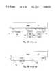
- FIGS. 1A and 1BThe calibration setup and required connections to physical standards for an insertable device are shown in FIGS. 1A and 1B.
- an insertable devicerequires a minimum of six one-port (short, open, load) calibration standards 100, 102, 104, 106, 108 and 110 to be connected in succession to the VNA 112 ports 114 and 116, respectively, (three for each port) and measured, and one through-connection (FIG. 1B) in order to determine the twelve terms of an error correction model.
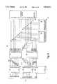
- a non-insertable devicerequires that a minimum of twelve one-port calibration standards 120, 122, 124, 126, 128 and 130 (FIG. 2A) and 132, 134, 136, 138, 140 and 142 (FIG. 3A) be connected to the VNA ports 114 and 116 and measured. Furthermore, two through-connections must be made (FIGS. 2B and 3B) in order to perform a full two-port calibration. This technique requires that an adapter 144 with the same sex and family of the DUT be alternatively connected to each port 114 and 116 of the VNA 112 and a full two-port calibration be performed with the appropriate calibration standards.
- a non-insertable full two-port calibrationrequires a minimum of twelve one-port and two through-connections.
- a sliding terminationis typically used instead of a matched load termination.
- a disadvantage of the sliding terminationis that a measurement should be performed for at least three slide positions in order to obtain reliable measurements. It is common in practice to use five slide positions for the matched load measurement at each port thereby resulting in a total of ten matched load position measurements.
- a minimum of eighteen measurements and seven connectionsis standard; and for a non-insertable calibration a minimum of thirty-six measurements and thirteen connections is standard.
- a disadvantage of the above-described calibration procedureis that each calibration standard must be connected and measured one at a time. This procedure involves connecting the standard to the VNA port using the appropriate hardware to ensure proper connection and once proper connection is ensured, pressing the appropriate hardware key on the VNA to make the appropriate measurement. In addition, once the measurement has been made, the standard must be disconnected and another standard must be connected using the same procedure. As discussed above, this procedure is repeated for a minimum of seven connections and eighteen measurements with a broadband insertable DUT and a minimum of thirteen connections and thirty-six measurements to measure a broadband non-insertable DUT.
- a non-trained operatormay confuse the standards (which are often confusingly similar in appearance) and operate the wrong hardware key on the VNA, measuring the wrong calibration standard. If the mistake is discovered at the end of the calibration, then the entire calibration must be repeated.
- the calibrationis not verified by the operator, via the use of a verification standard, after the full two-port calibration, the operator typically does not know that the calibration is flawed and that the DUT measurements are incorrect.
- Still another disadvantage of the prior art method of calibrationis that the manual calibration procedure tends to be cumbersome and slow. Thus, a significant portion of valuable testing time is spent each day calibrating the VNA. If the calibration is not done correctly, then the operator must start over. The VNA should be recalibrated, depending upon the application, at least once each day in order to ensure appropriate measurement accuracy.
- the calibration according to this method and apparatuscan be performed automatically.
- the present inventionis directed to a method and apparatus for providing a programmable broadband, highly stable and repeatable two-port network to be used in determining the systematic errors of a VNA.
- the two-port network of the present inventionis comprised of a number of semiconductor devices interconnected through transmission lines.
- Each semiconductor devicecan be forward or reverse biased by programmable digital control circuitry.
- a multitude of well-known reflection coefficientscan, therefore, be generated at each port of the two-port network by forward or reverse biasing selected semiconductor devices via the programmable digital circuitry.
- all of the semiconductorscan be reverse biased such that the two-port network provides a low-loss transmission through-connection between the two ports of the network.
- a high isolationcan be obtained between the two ports of the network by forward biasing several or all of the semiconductor devices simultaneously.
- the programmable two-port networkcan be connected to each port of the VNA in order to provide multiple complex reflection coefficients to each port of the VNA. These well-known multiple reflection coefficients can be used as calibration standards at each port of the VNA for a one-port calibration.
- a full two-port calibrationcan be performed by providing, with the two-port network, multiple well-known reflection coefficients to each port of the VNA, a low-loss transmission through-connection between the two VNA ports and a high isolation condition between the two ports.
- FIGS. 1A and 1Bare schematic diagrams showing the calibration of a vector network analyzer for insertable devices to be measured according to the prior art
- FIGS. 2A and 2B and 3A and 3Bare schematic diagrams illustrating the calibration of a vector network analyzer for non-insertable devices to be measured using an adapter on each of the two ports according to the prior art;
- FIG. 4is a schematic diagram of a calibration setup according to this invention.
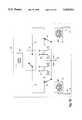
- FIG. 5is a more detailed schematic diagram of a two-port network circuit for use with the setup of FIG. 4 according to this invention.
- FIG. 6is a more detailed schematic diagram of a digital control circuit for operating the two-port network circuit of FIG. 5;
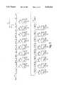
- FIG. 7is a flow-diagram of a two-port, twelve-term, error model for use with the two-port network according to this invention.
- FIG. 8is a flow diagram illustrating a computer control procedure for obtaining calibration coefficients using the two-port network according to this invention.
- FIG. 9is a schematic diagram of a self-calibration circuit using a pair of two-port networks according to this invention.
- FIG. 10is an alternative embodiment of a self-calibration circuit using two-port networks according to this invention.
- FIG. 4illustrates a measurement setup according to a preferred embodiment which can be used with the present invention to calibrate a VNA.
- the setupincludes the VNA 12, a two-port network 14 according to this invention to be connected to both ports of the VNA and a computer control 16.
- the computer control 16includes a data line 18 to the VNA 12 to receive the measured data from the VNA 12 and to control the VNA 12 with the aid of software stored in a local or permanent memory region 20 of the computer 16.
- the measurement setupalso includes a control line 22 between a two-port network interface 23 and the two-port network which allows the computer or the VNA to control the two-port network in accordance with the control software stored in the memory of the computer.
- the computer controlincludes a keyboard interface 24 for interaction with an operator. Note that while a computer 16 is illustrated in this embodiment, the computer functions can be incorporated into the VNA 12 or into a microprocessor or other hardware and software device directly provided to the network 14.
- FIG. 5is a schematic of the microwave circuitry 25 contained in the two-port network 14 of the present invention.
- This circuitryis of a type disclosed in Applicants' U.S. Pat. No. 5,034,708 relating to a Broadband Programmable Electronic Tuner. The teachings of this patent are expressly incorporated by reference hereinto.
- the microwave circuitry 25includes a number of pairs of PIN diodes D1-D16 and DC blocking capacitors C4-C19 in series which are separated according to this embodiment by various lengths of microstrip transmission line T1-T17.
- the series capacitor C4-C19 and PIN diode D1-D16 combinationsare shunted to ground 27.
- the DC blocking capacitors C4-C19establish the RF connection of the cathode side of each respective diode D1-D16 to ground.
- the transmission lines T1-T17are constructed from 10 mil thick, known dielectric substrates which are laminated with copper on both sides wherein one side is etched to the appropriate dimensions. While such transmission line is utilized, equivalent forms of transmission line that establish a given electrical length are contemplated according to this invention. Similarly, while PIN diodes are utilized, other forms of switching devices are contemplated.
- a DC bias currentis constantly established at connection J0.
- This currentis established by a +5 volt supply according to a preferred embodiment.
- This DC bias currentis supplied to the anode side of any of the PIN diodes D1-D16 through the RF bypass network consisting of RF coil inductor L1 and RF shunt capacitor C2.
- the RF bypass networkprevents the interaction of RF and DC signals.
- Any of the PIN diodes D1-D16can be forward biased by providing a DC current return path to the cathode sides of any of the diodes via any of the control lines connections J1-J16.
- Each control line connectionalso includes an RF bypass circuit consisting of a series RF coil L2-L17 and a shunt RF capacitor C20-C35 which prevents interaction between the RF signals and the DC bias signals.
- the DC blocking capacitors C1 and C3which are placed in series with the RF transmission lines at the input of PORT 1 and PORT 2, prevent the DC bias signals used to bias the PIN diodes from exiting the two-port network.
- the two-port networkallows for a multitude of conditions to be established over a broad frequency band at both of its PORTS 1 and 2. These conditions include presenting a multitude of complex impedances at each port, a low-loss through-connection between the ports and a high isolation condition.
- the length and width of the transmission lines T2-T16are chosen to ensure a unique phase relationship between each of the PIN diodes D1-D16.
- the selection of transmission line electrical lengthis based on the principle of prime numbers described in Applicants' U.S. Pat. No. 5,034,708 which is expressly incorporated hereinto by reference. This principle provides for minimizing the repetition of impedance values at either port of the two-port network.
- employing the prime number relationshipensures that the total line length from either input port of the two-port network to each diode is not evenly divisible by the line length from the input port to any other diode.
- other length relationshipscan be utilized according to this invention.
- the microwave circuitallows for a plurality of microwave impedances, spread across the complex reflection plane, to be presented at both ports of the two-port network by controlling the signal present at the control lines J1-J16.
- the microwave circuitcan be thought of as being a symmetrical circuit comprised of two equal circuits. Circuit one is comprised of transmission lines T2-T8 and the corresponding shunt PIN diode D1-D8 and series capacitor C4-C10 pairs between these transmission lines. Circuit two is comprised of transmission lines T10-T16 and the corresponding shunt PIN diode D9-D16 and series capacitor C12-C19 pairs. These two circuits are joined by transmission line T9 which is fed by the DC current supply connection J0 and the RF bypass network.
- transmission line length T2is equal to transmission line length T16
- T3equals T15
- T4equals T14
- T5equals T13
- T6equals T12
- T7equals T11
- T8equals T10.
- the length of the transmission line T9is chosen so that, at the lowest frequency of desired operation, the round trip electrical length between PORT 1 to PIN diode D1 and the round trip electrical length between PORT 1 and PIN diode is a minimum of 240 degrees of phase difference for the condition where each diode is alternatively forward biased and the electrical length is measured. Similarly, the same phase relationship will exist at the lowest frequency of operation when diodes D3 and D16 are forward biased one at a time and connection is made to PORT 2.
- the PIN diodescan be operated in one of two states. In a forward-biased state, the PIN diodes act as very small resistors (substantially short circuits). In a reverse-biased state, the PIN diodes can be modeled as a very small capacitor, at RF frequencies, and therefore a very high impedance (substantially open circuits). Establishing a DC ground connection to any of the control lines J1-J16 ensures that the appropriate diode is forward biased. Alternatively, any of the control lines J1-J16 can be set to a positive voltage substantially larger than that at port J0 so that the appropriate PIN diode will be reverse biased.
- the two-port networkacts as a large-value attenuator providing a substantial amount of isolation between PORTS 1 and 2.
- the two-port networkacts as a low-loss through-connection between PORTS 1 and 2.
- each capacitor C1-C3has a capacitance of 200 pF
- C4-C9has a capacitance of 100 pF
- C20-C35has a capacitance of 820 pF
- each inductorhas an inductance of 40 nH
- T90.627”
- each diodehas a periphery of 0.015" ⁇ 0.015" ⁇ 0.005" with a series resistance of 2 ohms and a junction capacitance of 0.1 pF.
- FIG. 6is a schematic of the digital circuit 29 included in the two-port network.
- the digital circuit 29provides the appropriate bias to the control ports J1-J16 in accordance with the control signal 22 received from the computer control line, as best shown in FIG. 4.
- the computer control signal 22is received by three commercially available Darlington transistor arrays U1, U2 and U7 (SN 75468).
- the Darlington transistor arrays U1, U2 and U7are configured to receive a 16-bit TTL signal output by the computer control line 22.
- the wordis transmitted on signal lines B0-B15 to U1 pins 1-7, U2 pins 1-7 and U7 pins 1-2 respectively.
- U1, U2 and U7 pins 8are connected to ground 27.
- a TTL logic high on any one input line B0-B15results in a corresponding output of the Darlington array U1, U2 or U7 providing a DC ground signal to the corresponding output control line B0 1 -B15 1 .
- Output control lines B0 1 -B6 1are connected to respective pins 16-10 of U1, B7 1 -B13 1 are connected to respective pins 16-10 of U2 and B14 1 and B15 1 are connected to respective pins 16 and 15 of U7.
- a TTL logic low input to any of the Darlington array input portsdoes not enable the corresponding Darlington array output and, thus, the corresponding control line B0 1 -B15 1 is pulled up to a +50 volt signal level which is presented to the corresponding PIN diode control line.
- a pair of 68 ohm resistor networks U3 and U4are placed between the output control lines B0 1 -B15 1 of the Darlington arrays U1, U2 and U7 and the corresponding output control lines B0 2 -B15 2 and are used to limit the current which can be drawn by each diode.
- a pair of one Mega-ohm resistor networks U5 and U6which are placed at the outputs B0 2 -B15 2 of the 68 ohm resistor networks which are in series with a +50 volt bias supply 33 according to this embodiment.
- the voltage supply 33 and resistor networks U5 and U6act as a pull-up network for each output control which is not selected by the input TTL, signal thereby ensuring that a strong reverse bias signal is maintained on each control line J1-J16 for a PIN diode which has not been selected.
- FIG. 7is a two-port, twelve-term error correction model 35 which may be used to model the systematic errors in a conventional VNA setup.
- Mstands for measurements made by the VNA which is being calibrated.
- Astands for actual measurements which were preformed by a VNA at a metrology laboratory;
- Fstands for measurement in the forward direction (looking into the two-port network from Port 1) and R indicates measurements in the reverse direction (looking into Port 2 of the two-port network).
- the error correction modelrequires the connection of a number of known calibration standards to the ports of the VNA in order to determine the error coefficients in the twelve-term error model.
- the accuracy of the calibrationis be increased where the number of impedances presented at both ports of the two-port can be greater than that required to compute the unknown error coefficients, and therefore the additional impedance measurements may be used to improve the accuracy for the unknown coefficients.
- the random error of the measurement calibrationis substantially reduced due to the fact that only one connection to the VNA ports is required. Thus, it is possible to reduce the random and systematic errors in the calibration and to improve the accuracy of the DUT measurement.
- the calibration speedwill be improved over that of the prior art where there is only one connection required to the VNA and because the computer control program automatically controls the calibration without the need for operator input.
- An additional benefitis that the connector configuration of the DUT to be characterized does not change the calibration so long as the connectors on the two-port network are compatible with the DUT.
- the two-port networkpresents a verification standard to the VNA, post calibration in order to check that the calibration was performed correctly and to insure the accuracy of the calibration without the requirement of additional connections and/or disconnections to the VNA.
- the use of the computer control and elimination of multiple connections and disconnections to the VNAsubstantially eliminates possibility of human error in the calibration.
- the calibration deviceaccording to the invention can also be used as a verification or accreditation with other instruments in addition to a VNA because of its known characteristics. For example, this device can be used to verify the accuracy of a power meter.
- Equation 1is derived from a flow graph analysis on the two-port, twelve-term error correction model 35 of FIG. 7 to solve for the measured reflection coefficient at PORT 1 S 11M .
- S 11A , S 22A , S 21A , and S 12Aare the actual scattering parameters of the impedances presented by the two port network measured by the metrology laboratory VNA.
- Equation 2This condition is achieved practically, as described above, by forward biasing diodes D15 and D16 such that PORT 2 is isolated from PORT 1.
- the coefficient S 11Ais representative of the predetermined reflection coefficients measured by a VNA at a metrology laboratory (when diodes D15 and D16 and at least one other diode D1-D14 is "on") for various impedances presented at PORT 1. Therefore, by measuring at least three known impedances at PORT 1, the three error terms forward directivity EDF, forward reflection tracking ERF and forward source match ESF in Equation 2 can be solved for mathematically. Additionally, improved accuracy in the calibration measurements may be achieved, by measuring more than three impedances at PORT 1 and performing a least sum squares fitting algorithm on the computed error terms.
- Equation 3is the measured reflection coefficient S 22M equation derived using a flow graph analysis at PORT 2 based on the error model of FIG. 7. ##EQU3##
- a number of predetermined impedancescan be presented at PORT 2 by forward biasing diodes D1 and D2 and at least one of diodes D3-D16.
- the scattering coefficients S 11A , S 21A , S 22A , and S 12Aare the known scattering parameters measured at the metrology laboratory in the original characterization of the two-port network. The values are measured during the initial characterization of the two-port network for the conditions where all of the PIN diodes D1-D16 are reverse biased.
- the one-port error terms for PORT 1 and PORT 2were determined previously by the method described above. Therefore, by measuring the impedances at PORT 1 and PORT 2 where all of the PIN diodes are reverse biased, the error terms forward load match ELF and reverse load match ELR can be computed from Equations 9 and 10.
- the two-port networkcan then simulate known transmission and reflection coefficients which have not been presented during the calibration procedure described above and can be used as a verification standard for the purpose of checking the accuracy of the calibration. This can be done immediately after the calibration, with the aid of the software and without any need for connections or disconnections of the two-port network or any human intervention.
- the two-port networkmay be used as a calibration standard by other VNAs. Accordingly, it is desirable that the two-port network continue to reproduce the same conditions at its two ports that were measured by the VNA of the metrology laboratory.
- a heateris provided to insure the long term temperature stability of the electronic circuitry of the present invention.
- the temperatureis fixed at a temperature of 41° C. using a heating element located within a box or other enclosure for the circuitry (not shown).
- a flow diagram 41 of a method of controlling and calibrating the VNAis shown.
- the userinputs the frequencies to the computer (Step 28) at which a measurement of the DUT is to be performed.
- the frequenciesare then correlated (Step 30) with the frequencies of the premeasured two-port device to determine at which frequencies the calibration should be performed.
- the VNAis set up (Step 32) by loading the frequencies into the VNA in order to perform the calibration.
- the measurement of the two-port networkis performed (Step 34), according to the method described above.
- the error terms of the error modelare computed (Step 36). These error terms are then used to interpolate to the appropriate frequencies for the DUT to be measured (Step 38).
- the VNAis then restored to its initial condition (Step 40) so that the two-port network can be disconnected and the DUT can be connected for measurement.
- control routine 41is provided by a computer 16 (FIG. 4) having interconnections with the two-port network 14 and VNA 12.
- the computeris interconnected via line 18 to a standard port using a IEEE-488 standard connector.
- the functions of computer 16can be incorporated directly into the two-port network 14 or can be provided to the VNA 12.
- Another application of the two-port network of the present inventionis that it can be placed inside the VNA test set in order to derive a self-calibrating circuit 48 for a VNA.
- the two essentially identical two-port microwave networks 50 and 52are placed after the couplers 54, 55, 56 and 57 and present reflections at PORT 1 and PORT 2 of the VNA test set. With this embodiment, it is possible to calibrate the two networks once and thereafter to use the two networks as a self-calibrating VNA.
- the initial calibration procedure to characterize the self-calibrating VNAis accomplished by performing a calibration at the device reference plane 58. This is accomplished by reverse biasing all of the PIN diodes in each two-port network in order to establish a low loss through each network.
- the signal from signal source 68may then be presented to PORT 1 by selecting the appropriate position of switch 62.
- the PIN diodes of the output two-port microwave networkare forward biased in order to step through different impedances.
- the reflection coefficients resulting from the various impedances presented by the output two-port microwave network 52are measured at the device reference plane 58 thereby characterizing the output two-port microwave network 52.
- the input two-port microwave network 50is characterized by reverse biasing all of the PIN diodes of the output two-port microwave network switching the position of switch 62 to send the RF signal to PORT 2 and stepping the PIN diodes of the input two-port microwave network 50 through various impedances and measuring the reflection coefficients at the device reference plane 58.
- the two-port networkscan then be stepped through various impedances according to the steps described below to self-calibrate the VNA, without the need for making numerous connections or disconnections to PORTS 1 or 2 of the VNA or the need for human intervention.
- the steps of the self-calibration procedure of a self-calibrating VNA as initially characterized aboveare as follows according to one embodiment:
- Equations 9 and 10determine forward ELF and reverse ELR load match error terms by reverse biasing all of the PIN diodes of both the input and output microwave network and utilizing Equations 9 and 10 as discussed above.
- Equations 11 and 12are known, with the exception of forward isolation EXF and reverse isolation EXR, by disconnecting the through-connection between PORTS 1 and 2 and reverse biasing, all of the PIN diodes of the input and output two-port networks, the error terms EXF and EXR can be calculated utilizing Equations 7 and 8 as discussed previously. With the error terms EXF and EXR known, forward transmission tracking ETF and reverse transmission tracking ETR can be calculated utilizing Equations 11 and 12. Thus, all of the error terms can be calculated with the embodiment as shown in FIG. 9. Since the cable between PORTS 1 and 2 should be disconnected in order to make the DUT measurements, no extra steps are needed with the technique described above.
- FIG. 10is an alternate embodiment of a self-calibrating circuit 60 for a VNA which can be utilized in the same manner as described above with respect to the embodiment in FIG. 9, except that the initial calibration utilizing the conventional calibration technique is performed with single-pole-double-throw switches 62 and 64 configured such that PORT 1 and PORT 2 are connected to the throws 63 and 65 which are connected to the cabling 67 from the signal source 68.
- Each of the input and output two-port microwave networks 72 and 70respectively are connected to ground via resistor R having a value of 50 ohms.
- the self-calibration routinecan be performed using the steps described above where the single pole double throw switches will be connected to the two-port microwave network which is being utilized to establish the known impedances.
- single-pole-double-throw switch 62is connected to the signal source 68, while single-pole-double-throw switch 64 is connected to the output two-port microwave network 70 to characterize the output two-port microwave network 70.
- single-pole-double-throw switch 65is connected to the signal source 68 while single-pole-double-throw switch 62 is connected to the input two-port microwave network 72 to characterize the input two-port microwave network 72.
Landscapes
- Physics & Mathematics (AREA)
- General Physics & Mathematics (AREA)
- Measurement Of Resistance Or Impedance (AREA)
Abstract
Description
Det [SA]=S.sub.11A S.sub.22A -S.sub.21 A S.sub.12A
S.sub.21M =EXF (7)
S.sub.12M =EXR (8)
Claims (14)
Priority Applications (8)
| Application Number | Priority Date | Filing Date | Title |
|---|---|---|---|
| US08/066,534US5434511A (en) | 1993-05-24 | 1993-05-24 | Electronic microwave calibration device |
| US08/156,277US5467021A (en) | 1993-05-24 | 1993-11-22 | Calibration method and apparatus |
| JP6110015AJPH07198767A (en) | 1993-05-24 | 1994-05-24 | Method and device for electronic constitution |
| EP94303697AEP0626588A1 (en) | 1993-05-24 | 1994-05-24 | Electronic calibration method and apparatus |
| US08/477,995US5537046A (en) | 1993-05-24 | 1995-06-07 | Electronic calibration method and apparatus |
| US08/473,724US5548221A (en) | 1993-05-24 | 1995-06-07 | Electronic calibration method and apparatus |
| US08/474,748US5552714A (en) | 1993-05-24 | 1995-06-07 | Electronic calibration method and apparatus |
| US08/484,528US5578932A (en) | 1993-05-24 | 1995-06-07 | Method and apparatus for providing and calibrating a multiport network analyzer |
Applications Claiming Priority (1)
| Application Number | Priority Date | Filing Date | Title |
|---|---|---|---|
| US08/066,534US5434511A (en) | 1993-05-24 | 1993-05-24 | Electronic microwave calibration device |
Related Child Applications (1)
| Application Number | Title | Priority Date | Filing Date |
|---|---|---|---|
| US08/156,277Continuation-In-PartUS5467021A (en) | 1993-05-24 | 1993-11-22 | Calibration method and apparatus |
Publications (1)
| Publication Number | Publication Date |
|---|---|
| US5434511Atrue US5434511A (en) | 1995-07-18 |
Family
ID=22070126
Family Applications (1)
| Application Number | Title | Priority Date | Filing Date |
|---|---|---|---|
| US08/066,534Expired - LifetimeUS5434511A (en) | 1993-05-24 | 1993-05-24 | Electronic microwave calibration device |
Country Status (1)
| Country | Link |
|---|---|
| US (1) | US5434511A (en) |
Cited By (38)
| Publication number | Priority date | Publication date | Assignee | Title |
|---|---|---|---|---|
| US5572160A (en)* | 1994-12-01 | 1996-11-05 | Teradyne, Inc. | Architecture for RF signal automatic test equipment |
| US5587934A (en)* | 1993-10-21 | 1996-12-24 | Wiltron Company | Automatic VNA calibration apparatus |
| US5661404A (en)* | 1994-07-27 | 1997-08-26 | Hewlett-Packard Company | Circuit network measurement device and calibration method |
| US5715183A (en)* | 1994-12-07 | 1998-02-03 | Wiltron Company | Internal automatic calibrator for vector network analyzers |
| US5773985A (en)* | 1996-06-05 | 1998-06-30 | Wiltron Company | One port complex transmission and group delay measurements |
| US5825669A (en)* | 1996-12-17 | 1998-10-20 | Wiltron Company | Method of updating automatic calibration to provide a perceived perfect through connection |
| US6230106B1 (en) | 1999-10-13 | 2001-05-08 | Modulation Instruments | Method of characterizing a device under test |
| US6249128B1 (en) | 1997-10-22 | 2001-06-19 | Teradyne, Inc. | Automated microwave test system with improved accuracy |
| US6300775B1 (en) | 1999-02-02 | 2001-10-09 | Com Dev Limited | Scattering parameter calibration system and method |
| GB2382662A (en)* | 2001-11-29 | 2003-06-04 | Univ Cardiff | High frequency analyser |
| US6614237B2 (en) | 2000-09-18 | 2003-09-02 | Agilent Technologies, Inc. | Multiport automatic calibration device for a multiport test system |
| US20040051538A1 (en)* | 2002-09-16 | 2004-03-18 | Adamian Vahe?Apos; A. | Method and system for calibrating a measurement device path and for measuring a device under test in the calibrated measurement device path |
| US20040095145A1 (en)* | 2002-11-14 | 2004-05-20 | Ali Boudiaf | Method and apparatus for performing multiport through-reflect-line calibration and measurement |
| US6744262B2 (en) | 2002-03-14 | 2004-06-01 | Agilent Technologies, Inc. | Method, apparatus, and article of manufacture for characterizing a device and predicting electrical behavior of the device in a circuit |
| US6757625B2 (en) | 2002-04-22 | 2004-06-29 | Agilent Technologies, Inc. | Method, apparatus, and article of manufacture for predicting electrical behavior of a multiport device having balanced device ports |
| US20040150411A1 (en)* | 2003-01-30 | 2004-08-05 | Liu James C. | Electronic calibration circuit for calibrating a network analyzer |
| US20040193382A1 (en)* | 2000-09-18 | 2004-09-30 | Adamian Vahe' A. | Method and apparatus for calibrating a multiport test system for measurement of a DUT |
| US20050030047A1 (en)* | 2003-08-05 | 2005-02-10 | Vahe Adamian | Method and apparatus for measuring a device under test using an improved through-reflect-line measurement calibration |
| US20050107972A1 (en)* | 2003-11-13 | 2005-05-19 | Wong Kenneth H. | Obtaining calibration parameters for a three-port device under test |
| US20050138577A1 (en)* | 2003-12-18 | 2005-06-23 | Vahe Adamian | Method, apparatus, and article of manufacture for manufacturing high frequency balanced circuits |
| US6965241B1 (en) | 2003-10-07 | 2005-11-15 | Agilent Technologies, Inc. | Automated electronic calibration apparatus |
| US7030625B1 (en) | 2005-01-18 | 2006-04-18 | Agilent Technologies, Inc. | Method and apparatus for performing a minimum connection multiport through-reflect-line calibration and measurement |
| GB2424714A (en)* | 2005-03-30 | 2006-10-04 | Agilent Technologies Inc | Vector network analyser |
| DE19828682B4 (en)* | 1997-08-26 | 2007-02-08 | Agilent Technologies, Inc. (n.d.Ges.d.Staates Delaware), Palo Alto | Automatic calibration of a network analyzer |
| US20090184721A1 (en)* | 2008-01-17 | 2009-07-23 | Albert-Lebrun Xavier M H | Method and system for tracking scattering parameter test system calibration |
| US20090322347A1 (en)* | 2008-06-26 | 2009-12-31 | Dune Medical Devices Ltd. | Rf calibration device and method |
| EP2244096A1 (en)* | 2009-04-23 | 2010-10-27 | EADS Deutschland GmbH | Calibration method for testing HF modules |
| US20110199107A1 (en)* | 2010-02-12 | 2011-08-18 | Ate Systems, Inc. | Method and apparatus for calibrating a test system for measuring a device under test |
| CN101258412B (en)* | 2005-09-01 | 2013-02-20 | 株式会社村田制作所 | Measuring method and measuring device of scattering coefficient of object to be tested |
| RU2524049C1 (en)* | 2013-02-14 | 2014-07-27 | Федеральное государственное бюджетное образовательное учреждение высшего профессионального образования "Кубанский государственный университет" (ФГБОУ ВПО "КубГУ") | Device for measuring absolute complex transmission and reflection coefficients of microwave devices with frequency conversion |
| CN104198788A (en)* | 2014-09-09 | 2014-12-10 | 南京捷希科技有限公司 | VNA (Vector Network Analyzer) multiplexing instrument and method |
| DE102013226065A1 (en)* | 2013-12-16 | 2015-06-18 | Rohde & Schwarz Gmbh & Co. Kg | Method for the controlled connection of a calibration standard in a calibration module and an associated calibration module |
| RU2564861C1 (en)* | 2014-07-17 | 2015-10-10 | Федеральное государственное бюджетное образовательное учреждение высшего профессионального образования "Кубанский государственный университет" (ФГБОУ ВПО "КубГУ") | Device to measure group time of delay of frequency converters |
| US10073074B1 (en)* | 2014-04-25 | 2018-09-11 | Iowa State University Research Foundation, Inc. | Low RF-band impedance spectroscopy based sensor for in-situ, wireless soil sensing |
| RU2673781C1 (en)* | 2017-12-13 | 2018-11-29 | Федеральное государственное бюджетное образовательное учреждение высшего образования "Кубанский государственный университет" (ФГБОУ ВО "КубГУ") | Method for calibrating two-channel superheterodyne receiver in meter of complex transmission and reflection coefficients of microwave devices with frequency conversion |
| US10938490B1 (en)* | 2018-10-31 | 2021-03-02 | Christos Tsironis | Calibration method for coupler-tuner assembly |
| US10962587B2 (en) | 2018-11-28 | 2021-03-30 | Fermi Research Alliance, Llc | Method and system for microwave mixer phase response measurement |
| US11431379B1 (en)* | 2021-03-31 | 2022-08-30 | Teradyne, Inc. | Front-end module |
Citations (16)
| Publication number | Priority date | Publication date | Assignee | Title |
|---|---|---|---|---|
| US3454906A (en)* | 1967-05-02 | 1969-07-08 | Texas Instruments Inc | Bisected diode loaded line phase shifter |
| US3559108A (en)* | 1969-08-21 | 1971-01-26 | Bell Telephone Labor Inc | Coupler switches |
| US4450419A (en)* | 1982-09-29 | 1984-05-22 | Rca Corporation | Monolithic reflection phase shifter |
| EP0150410A1 (en)* | 1984-01-09 | 1985-08-07 | Hewlett-Packard Company | Vector network analyzer |
| US4680538A (en)* | 1985-01-15 | 1987-07-14 | Cornell Research Foundation, Inc. | Millimeter wave vector network analyzer |
| SU1345140A1 (en)* | 1986-01-27 | 1987-10-15 | Горьковский политехнический институт им.А.А.Жданова | Method of calibrating contact device |
| US4764740A (en)* | 1987-08-10 | 1988-08-16 | Micronav Ltd. | Phase shifter |
| US4816767A (en)* | 1984-01-09 | 1989-03-28 | Hewlett-Packard Company | Vector network analyzer with integral processor |
| WO1989004001A1 (en)* | 1987-10-27 | 1989-05-05 | Martin Marietta Corporation | Calibrating method for apparatus evaluating microwave/millimeter wave circuits |
| US4839578A (en)* | 1987-06-04 | 1989-06-13 | Eip Microwave, Inc. | Method for removing phase instabilities caused by flexure of cables in microwave network analyzer measurements |
| US4939485A (en)* | 1988-12-09 | 1990-07-03 | Varian Associates, Inc. | Microwave field effect switch |
| US4982164A (en)* | 1988-04-22 | 1991-01-01 | Rhode & Schwarz Gmbh & Co. K.G. | Method of calibrating a network analyzer |
| US5034708A (en)* | 1989-05-16 | 1991-07-23 | Automatic Testing And Networking, Inc. | Programmable broadband electronic tuner |
| US5047725A (en)* | 1989-11-28 | 1991-09-10 | Cascade Microtech, Inc. | Verification and correction method for an error model for a measurement network |
| US5097215A (en)* | 1989-04-07 | 1992-03-17 | Laboratorium Prof. Dr. Rudolf Berthold Gmbh & Co. | Methods for establishing the complex measuring capacity of homodyne network analyzers |
| US5109204A (en)* | 1990-12-03 | 1992-04-28 | Honeywell Inc. | High power RF precision attenuator |
- 1993
- 1993-05-24USUS08/066,534patent/US5434511A/ennot_activeExpired - Lifetime
Patent Citations (16)
| Publication number | Priority date | Publication date | Assignee | Title |
|---|---|---|---|---|
| US3454906A (en)* | 1967-05-02 | 1969-07-08 | Texas Instruments Inc | Bisected diode loaded line phase shifter |
| US3559108A (en)* | 1969-08-21 | 1971-01-26 | Bell Telephone Labor Inc | Coupler switches |
| US4450419A (en)* | 1982-09-29 | 1984-05-22 | Rca Corporation | Monolithic reflection phase shifter |
| EP0150410A1 (en)* | 1984-01-09 | 1985-08-07 | Hewlett-Packard Company | Vector network analyzer |
| US4816767A (en)* | 1984-01-09 | 1989-03-28 | Hewlett-Packard Company | Vector network analyzer with integral processor |
| US4680538A (en)* | 1985-01-15 | 1987-07-14 | Cornell Research Foundation, Inc. | Millimeter wave vector network analyzer |
| SU1345140A1 (en)* | 1986-01-27 | 1987-10-15 | Горьковский политехнический институт им.А.А.Жданова | Method of calibrating contact device |
| US4839578A (en)* | 1987-06-04 | 1989-06-13 | Eip Microwave, Inc. | Method for removing phase instabilities caused by flexure of cables in microwave network analyzer measurements |
| US4764740A (en)* | 1987-08-10 | 1988-08-16 | Micronav Ltd. | Phase shifter |
| WO1989004001A1 (en)* | 1987-10-27 | 1989-05-05 | Martin Marietta Corporation | Calibrating method for apparatus evaluating microwave/millimeter wave circuits |
| US4982164A (en)* | 1988-04-22 | 1991-01-01 | Rhode & Schwarz Gmbh & Co. K.G. | Method of calibrating a network analyzer |
| US4939485A (en)* | 1988-12-09 | 1990-07-03 | Varian Associates, Inc. | Microwave field effect switch |
| US5097215A (en)* | 1989-04-07 | 1992-03-17 | Laboratorium Prof. Dr. Rudolf Berthold Gmbh & Co. | Methods for establishing the complex measuring capacity of homodyne network analyzers |
| US5034708A (en)* | 1989-05-16 | 1991-07-23 | Automatic Testing And Networking, Inc. | Programmable broadband electronic tuner |
| US5047725A (en)* | 1989-11-28 | 1991-09-10 | Cascade Microtech, Inc. | Verification and correction method for an error model for a measurement network |
| US5109204A (en)* | 1990-12-03 | 1992-04-28 | Honeywell Inc. | High power RF precision attenuator |
Non-Patent Citations (17)
| Title |
|---|
| Adamian, V., "Stable Source Aids Automated Noise-Parameter Measurements", The Time and Measurement Notebook, Feb., 1988, pp. 51-58. |
| Adamian, V., Stable Source Aids Automated Noise Parameter Measurements , The Time and Measurement Notebook, Feb., 1988, pp. 51 58.* |
| Cronson: "A Six-Port Automatic Network Analyzer" IEEE Trans. on Microwave Theory-Dec. 1977-pp. 1086-1091. |
| Cronson: A Six Port Automatic Network Analyzer IEEE Trans. on Microwave Theory Dec. 1977 pp. 1086 1091.* |
| Curran, J., "TRL Calibration for Non-Coaxial Measurements", Hewlett-Packard, (1987). |
| Curran, J., TRL Calibration for Non Coaxial Measurements , Hewlett Packard, (1987).* |
| Ferrero, A. and Pisani, U., "Two-Port Network Analyzer Calibration Using an Unknown Thru", IEEE Microwave and Guided Wave Letters, vol. 2, No. 12, Dec. 1992, pp. 505-507. |
| Ferrero, A. and Pisani, U., Two Port Network Analyzer Calibration Using an Unknown Thru , IEEE Microwave and Guided Wave Letters, vol. 2, No. 12, Dec. 1992, pp. 505 507.* |
| Froelich, R., "Automated Tuning for Noise Parameter Measurements Using a Microwave Probe", Watkins-Johnson Co., Mar. 1989, pp. 83-96. |
| Froelich, R., "Measurement of GaAs FET Noise Parameters", Watkins-Johnson Co., vol. 13, No. 6, Nov./Dec. 1986, pp. 2-11. |
| Froelich, R., Automated Tuning for Noise Parameter Measurements Using a Microwave Probe , Watkins Johnson Co., Mar. 1989, pp. 83 96.* |
| Froelich, R., Measurement of GaAs FET Noise Parameters , Watkins Johnson Co., vol. 13, No. 6, Nov./Dec. 1986, pp. 2 11.* |
| Hewlett Packard Network Analyzers, Test & Measurement Catalog, Oct. 1991, USA.* |
| Hewlett Packard Product Note 8510 5A, Specifying Calibration Standards for the HP 8510 Network Analyzer , Feb. 1, 1988.* |
| Hewlett-Packard Product Note 8510-5A, "Specifying Calibration Standards for the HP 8510 Network Analyzer", Feb. 1, 1988. |
| Rytting, D., "Advances in Microwave Error Correction Techniques", Hewlett-Packard, Jun. 1, 1987, pp. 1-39. |
| Rytting, D., Advances in Microwave Error Correction Techniques , Hewlett Packard, Jun. 1, 1987, pp. 1 39.* |
Cited By (60)
| Publication number | Priority date | Publication date | Assignee | Title |
|---|---|---|---|---|
| US5587934A (en)* | 1993-10-21 | 1996-12-24 | Wiltron Company | Automatic VNA calibration apparatus |
| US5661404A (en)* | 1994-07-27 | 1997-08-26 | Hewlett-Packard Company | Circuit network measurement device and calibration method |
| US6066953A (en)* | 1994-12-01 | 2000-05-23 | Teradyne, Inc. | Architecture for RF signal automatic test equipment |
| US5572160A (en)* | 1994-12-01 | 1996-11-05 | Teradyne, Inc. | Architecture for RF signal automatic test equipment |
| US5715183A (en)* | 1994-12-07 | 1998-02-03 | Wiltron Company | Internal automatic calibrator for vector network analyzers |
| US5773985A (en)* | 1996-06-05 | 1998-06-30 | Wiltron Company | One port complex transmission and group delay measurements |
| US5825669A (en)* | 1996-12-17 | 1998-10-20 | Wiltron Company | Method of updating automatic calibration to provide a perceived perfect through connection |
| DE19828682B4 (en)* | 1997-08-26 | 2007-02-08 | Agilent Technologies, Inc. (n.d.Ges.d.Staates Delaware), Palo Alto | Automatic calibration of a network analyzer |
| US6249128B1 (en) | 1997-10-22 | 2001-06-19 | Teradyne, Inc. | Automated microwave test system with improved accuracy |
| US6300775B1 (en) | 1999-02-02 | 2001-10-09 | Com Dev Limited | Scattering parameter calibration system and method |
| US6230106B1 (en) | 1999-10-13 | 2001-05-08 | Modulation Instruments | Method of characterizing a device under test |
| US6826506B2 (en) | 2000-09-18 | 2004-11-30 | Agilent Technologies, Inc. | Method and apparatus for calibrating a multiport test system for measurement of a DUT |
| US20040193382A1 (en)* | 2000-09-18 | 2004-09-30 | Adamian Vahe' A. | Method and apparatus for calibrating a multiport test system for measurement of a DUT |
| US6920407B2 (en) | 2000-09-18 | 2005-07-19 | Agilent Technologies, Inc. | Method and apparatus for calibrating a multiport test system for measurement of a DUT |
| US6653848B2 (en)* | 2000-09-18 | 2003-11-25 | Agilent Technologies, Inc. | Method and apparatus for linear characterization of multi-terminal single-ended or balanced devices |
| US6614237B2 (en) | 2000-09-18 | 2003-09-02 | Agilent Technologies, Inc. | Multiport automatic calibration device for a multiport test system |
| GB2382662B (en)* | 2001-11-29 | 2003-12-10 | Univ Cardiff | High frequency circuit analyzer |
| GB2382662A (en)* | 2001-11-29 | 2003-06-04 | Univ Cardiff | High frequency analyser |
| US6744262B2 (en) | 2002-03-14 | 2004-06-01 | Agilent Technologies, Inc. | Method, apparatus, and article of manufacture for characterizing a device and predicting electrical behavior of the device in a circuit |
| US20040160230A1 (en)* | 2002-03-14 | 2004-08-19 | Adamian Vahe A. | Method, apparatus, and article of manufacture for characterizing a device and predicting electrical behavior of the device in a circuit |
| US6937032B2 (en) | 2002-03-14 | 2005-08-30 | Agilent Technologies, Inc. | Method, apparatus, and article of manufacture for characterizing a device and predicting electrical behavior of the device in a circuit |
| US6757625B2 (en) | 2002-04-22 | 2004-06-29 | Agilent Technologies, Inc. | Method, apparatus, and article of manufacture for predicting electrical behavior of a multiport device having balanced device ports |
| US7019535B2 (en) | 2002-09-16 | 2006-03-28 | Agilent Technologies, Inc. | Method and system for calibrating a measurement device path and for measuring a device under test in the calibrated measurement device path |
| DE10338072B4 (en)* | 2002-09-16 | 2007-02-08 | Agilent Technologies, Inc. (n.d.Ges.d.Staates Delaware), Palo Alto | A method and apparatus for calibrating a gauge path and measuring the S-parameters of a test fixture in the calibrated gauge path |
| US20040051538A1 (en)* | 2002-09-16 | 2004-03-18 | Adamian Vahe?Apos; A. | Method and system for calibrating a measurement device path and for measuring a device under test in the calibrated measurement device path |
| US6853198B2 (en) | 2002-11-14 | 2005-02-08 | Agilent Technologies, Inc. | Method and apparatus for performing multiport through-reflect-line calibration and measurement |
| US20040095145A1 (en)* | 2002-11-14 | 2004-05-20 | Ali Boudiaf | Method and apparatus for performing multiport through-reflect-line calibration and measurement |
| US20040150411A1 (en)* | 2003-01-30 | 2004-08-05 | Liu James C. | Electronic calibration circuit for calibrating a network analyzer |
| US6914436B2 (en) | 2003-01-30 | 2005-07-05 | Agilent Technologies, Inc. | Electronic calibration circuit for calibrating a network analyzer |
| US20050030047A1 (en)* | 2003-08-05 | 2005-02-10 | Vahe Adamian | Method and apparatus for measuring a device under test using an improved through-reflect-line measurement calibration |
| US7068049B2 (en) | 2003-08-05 | 2006-06-27 | Agilent Technologies, Inc. | Method and apparatus for measuring a device under test using an improved through-reflect-line measurement calibration |
| US6965241B1 (en) | 2003-10-07 | 2005-11-15 | Agilent Technologies, Inc. | Automated electronic calibration apparatus |
| US7013229B2 (en) | 2003-11-13 | 2006-03-14 | Agilent Technologies, Inc. | Obtaining calibration parameters for a three-port device under test |
| US20050107972A1 (en)* | 2003-11-13 | 2005-05-19 | Wong Kenneth H. | Obtaining calibration parameters for a three-port device under test |
| US7126346B2 (en) | 2003-12-18 | 2006-10-24 | Agilent Technologies, Inc. | Method, apparatus, and article of manufacture for manufacturing high frequency balanced circuits |
| US20050138577A1 (en)* | 2003-12-18 | 2005-06-23 | Vahe Adamian | Method, apparatus, and article of manufacture for manufacturing high frequency balanced circuits |
| US7030625B1 (en) | 2005-01-18 | 2006-04-18 | Agilent Technologies, Inc. | Method and apparatus for performing a minimum connection multiport through-reflect-line calibration and measurement |
| GB2424714A (en)* | 2005-03-30 | 2006-10-04 | Agilent Technologies Inc | Vector network analyser |
| US20060226856A1 (en)* | 2005-03-30 | 2006-10-12 | Wong Kenneth H | VNA and method for addressing transmission line effects in VNA measurement data |
| US7148702B2 (en) | 2005-03-30 | 2006-12-12 | Agilent Technologies, Inc. | VNA and method for addressing transmission line effects in VNA measurement data |
| CN101258412B (en)* | 2005-09-01 | 2013-02-20 | 株式会社村田制作所 | Measuring method and measuring device of scattering coefficient of object to be tested |
| US7777497B2 (en) | 2008-01-17 | 2010-08-17 | Com Dev International Ltd. | Method and system for tracking scattering parameter test system calibration |
| US20090184721A1 (en)* | 2008-01-17 | 2009-07-23 | Albert-Lebrun Xavier M H | Method and system for tracking scattering parameter test system calibration |
| US8319502B2 (en)* | 2008-06-26 | 2012-11-27 | Dune Medical Devices Ltd. | RF calibration device and method |
| CN102077109B (en)* | 2008-06-26 | 2015-04-15 | 沙丘医疗设备有限公司 | RF calibration device and method |
| WO2009156982A3 (en)* | 2008-06-26 | 2010-05-06 | Dune Medical Devices Ltd. | Rf calibration device and method |
| US20090322347A1 (en)* | 2008-06-26 | 2009-12-31 | Dune Medical Devices Ltd. | Rf calibration device and method |
| EP2244096A1 (en)* | 2009-04-23 | 2010-10-27 | EADS Deutschland GmbH | Calibration method for testing HF modules |
| US20110199107A1 (en)* | 2010-02-12 | 2011-08-18 | Ate Systems, Inc. | Method and apparatus for calibrating a test system for measuring a device under test |
| RU2524049C1 (en)* | 2013-02-14 | 2014-07-27 | Федеральное государственное бюджетное образовательное учреждение высшего профессионального образования "Кубанский государственный университет" (ФГБОУ ВПО "КубГУ") | Device for measuring absolute complex transmission and reflection coefficients of microwave devices with frequency conversion |
| DE102013226065B4 (en) | 2013-12-16 | 2020-06-18 | Rohde & Schwarz GmbH & Co. Kommanditgesellschaft | Method for the controlled connection of a calibration standard in a calibration module and an associated calibration module |
| DE102013226065A1 (en)* | 2013-12-16 | 2015-06-18 | Rohde & Schwarz Gmbh & Co. Kg | Method for the controlled connection of a calibration standard in a calibration module and an associated calibration module |
| US10132908B2 (en) | 2013-12-16 | 2018-11-20 | Rohde & Schwarz Gmbh & Co. Kg | Method for the controlled connection of a calibration standard in a calibration module and an associated calibration module |
| US10073074B1 (en)* | 2014-04-25 | 2018-09-11 | Iowa State University Research Foundation, Inc. | Low RF-band impedance spectroscopy based sensor for in-situ, wireless soil sensing |
| RU2564861C1 (en)* | 2014-07-17 | 2015-10-10 | Федеральное государственное бюджетное образовательное учреждение высшего профессионального образования "Кубанский государственный университет" (ФГБОУ ВПО "КубГУ") | Device to measure group time of delay of frequency converters |
| CN104198788A (en)* | 2014-09-09 | 2014-12-10 | 南京捷希科技有限公司 | VNA (Vector Network Analyzer) multiplexing instrument and method |
| RU2673781C1 (en)* | 2017-12-13 | 2018-11-29 | Федеральное государственное бюджетное образовательное учреждение высшего образования "Кубанский государственный университет" (ФГБОУ ВО "КубГУ") | Method for calibrating two-channel superheterodyne receiver in meter of complex transmission and reflection coefficients of microwave devices with frequency conversion |
| US10938490B1 (en)* | 2018-10-31 | 2021-03-02 | Christos Tsironis | Calibration method for coupler-tuner assembly |
| US10962587B2 (en) | 2018-11-28 | 2021-03-30 | Fermi Research Alliance, Llc | Method and system for microwave mixer phase response measurement |
| US11431379B1 (en)* | 2021-03-31 | 2022-08-30 | Teradyne, Inc. | Front-end module |
Similar Documents
| Publication | Publication Date | Title |
|---|---|---|
| US5434511A (en) | Electronic microwave calibration device | |
| US5537046A (en) | Electronic calibration method and apparatus | |
| US6060888A (en) | Error correction method for reflection measurements of reciprocal devices in vector network analyzers | |
| Rumiantsev et al. | VNA calibration | |
| Tippet et al. | A rigorous technique for measuring the scattering matrix of a multiport device with a 2-port network analyzer | |
| US6960920B2 (en) | Method for correcting measurement error and electronic component characteristic measurement apparatus | |
| US7107170B2 (en) | Multiport network analyzer calibration employing reciprocity of a device | |
| US7068046B2 (en) | Calibration techniques for simplified high-frequency multiport differential measurements | |
| US6147501A (en) | Automatic calibration of a network analyzer | |
| Rolfes et al. | Multiport method for the measurement of the scattering parameters of N-ports | |
| US5047725A (en) | Verification and correction method for an error model for a measurement network | |
| US6650123B2 (en) | Methods for determining characteristics of interface devices used with vector network analyzers | |
| US5608330A (en) | Method for calibrating a network analyzer according to the seven-term principle | |
| CN104237829B (en) | Overall calibration method for high-accuracy noise factor measuring system | |
| US6417674B1 (en) | Two port self-calibration for an N-port network analyzer | |
| US7064555B2 (en) | Network analyzer calibration employing reciprocity of a device | |
| Lu et al. | Port reduction methods for scattering matrix measurement of an n-port network | |
| JPH0843463A (en) | Circuit network measuring instrument and calibration method | |
| JP3668136B2 (en) | Multiport device analysis apparatus and analysis method and calibration method for multiport device analysis apparatus | |
| US6965241B1 (en) | Automated electronic calibration apparatus | |
| US7113891B2 (en) | Multi-port scattering parameter calibration system and method | |
| US6571187B1 (en) | Method for calibrating two port high frequency measurements | |
| JPH11211766A (en) | Automatic calibration device | |
| EP1455197A2 (en) | Calibration method and apparatus | |
| Bockelman et al. | Calibration and verification of the pure-mode vector network analyzer |
Legal Events
| Date | Code | Title | Description |
|---|---|---|---|
| AS | Assignment | Owner name:ATN MICROWAVE INC., MASSACHUSETTS Free format text:ASSIGNMENT OF ASSIGNORS INTEREST;ASSIGNORS:ADAMIAN, VAHE A.;FALCINELLI, MICHAEL T.;PHILLIPS, PETER V.;REEL/FRAME:006571/0695;SIGNING DATES FROM | |
| STPP | Information on status: patent application and granting procedure in general | Free format text:APPLICATION UNDERGOING PREEXAM PROCESSING | |
| FEPP | Fee payment procedure | Free format text:PAYOR NUMBER ASSIGNED (ORIGINAL EVENT CODE: ASPN); ENTITY STATUS OF PATENT OWNER: LARGE ENTITY | |
| CC | Certificate of correction | ||
| FPAY | Fee payment | Year of fee payment:4 | |
| SULP | Surcharge for late payment | ||
| FEPP | Fee payment procedure | Free format text:PAYER NUMBER DE-ASSIGNED (ORIGINAL EVENT CODE: RMPN); ENTITY STATUS OF PATENT OWNER: LARGE ENTITY Free format text:PAYOR NUMBER ASSIGNED (ORIGINAL EVENT CODE: ASPN); ENTITY STATUS OF PATENT OWNER: LARGE ENTITY | |
| FEPP | Fee payment procedure | Free format text:PAYER NUMBER DE-ASSIGNED (ORIGINAL EVENT CODE: RMPN); ENTITY STATUS OF PATENT OWNER: LARGE ENTITY Free format text:PAYOR NUMBER ASSIGNED (ORIGINAL EVENT CODE: ASPN); ENTITY STATUS OF PATENT OWNER: LARGE ENTITY | |
| AS | Assignment | Owner name:AGILENT TECHNOLOGIES, INC., CALIFORNIA Free format text:ASSIGNMENT OF ASSIGNORS INTEREST;ASSIGNOR:ATN MICROWAVE, INC.;REEL/FRAME:011679/0542 Effective date:20010613 | |
| FEPP | Fee payment procedure | Free format text:PAT HOLDER NO LONGER CLAIMS SMALL ENTITY STATUS, ENTITY STATUS SET TO UNDISCOUNTED (ORIGINAL EVENT CODE: STOL); ENTITY STATUS OF PATENT OWNER: LARGE ENTITY | |
| FEPP | Fee payment procedure | Free format text:PAYER NUMBER DE-ASSIGNED (ORIGINAL EVENT CODE: RMPN); ENTITY STATUS OF PATENT OWNER: LARGE ENTITY Free format text:PAYOR NUMBER ASSIGNED (ORIGINAL EVENT CODE: ASPN); ENTITY STATUS OF PATENT OWNER: LARGE ENTITY | |
| FPAY | Fee payment | Year of fee payment:8 | |
| FPAY | Fee payment | Year of fee payment:12 |