US5433711A - Syringe with cannula-protecting sheath and sealing center rod - Google Patents
Syringe with cannula-protecting sheath and sealing center rodDownload PDFInfo
- Publication number
- US5433711A US5433711AUS08/283,324US28332494AUS5433711AUS 5433711 AUS5433711 AUS 5433711AUS 28332494 AUS28332494 AUS 28332494AUS 5433711 AUS5433711 AUS 5433711A
- Authority
- US
- United States
- Prior art keywords
- bore
- syringe
- rod
- cannula
- interior
- Prior art date
- Legal status (The legal status is an assumption and is not a legal conclusion. Google has not performed a legal analysis and makes no representation as to the accuracy of the status listed.)
- Expired - Lifetime
Links
Images
Classifications
- A—HUMAN NECESSITIES
- A61—MEDICAL OR VETERINARY SCIENCE; HYGIENE
- A61M—DEVICES FOR INTRODUCING MEDIA INTO, OR ONTO, THE BODY; DEVICES FOR TRANSDUCING BODY MEDIA OR FOR TAKING MEDIA FROM THE BODY; DEVICES FOR PRODUCING OR ENDING SLEEP OR STUPOR
- A61M5/00—Devices for bringing media into the body in a subcutaneous, intra-vascular or intramuscular way; Accessories therefor, e.g. filling or cleaning devices, arm-rests
- A61M5/178—Syringes
- A61M5/31—Details
- A61M5/32—Needles; Details of needles pertaining to their connection with syringe or hub; Accessories for bringing the needle into, or holding the needle on, the body; Devices for protection of needles
- A61M5/3202—Devices for protection of the needle before use, e.g. caps
- A—HUMAN NECESSITIES
- A61—MEDICAL OR VETERINARY SCIENCE; HYGIENE
- A61M—DEVICES FOR INTRODUCING MEDIA INTO, OR ONTO, THE BODY; DEVICES FOR TRANSDUCING BODY MEDIA OR FOR TAKING MEDIA FROM THE BODY; DEVICES FOR PRODUCING OR ENDING SLEEP OR STUPOR
- A61M5/00—Devices for bringing media into the body in a subcutaneous, intra-vascular or intramuscular way; Accessories therefor, e.g. filling or cleaning devices, arm-rests
- A61M5/178—Syringes
- A61M5/31—Details
- A61M2005/3103—Leak prevention means for distal end of syringes, i.e. syringe end for mounting a needle
- A61M2005/3104—Caps for syringes without needle
- A—HUMAN NECESSITIES
- A61—MEDICAL OR VETERINARY SCIENCE; HYGIENE
- A61M—DEVICES FOR INTRODUCING MEDIA INTO, OR ONTO, THE BODY; DEVICES FOR TRANSDUCING BODY MEDIA OR FOR TAKING MEDIA FROM THE BODY; DEVICES FOR PRODUCING OR ENDING SLEEP OR STUPOR
- A61M5/00—Devices for bringing media into the body in a subcutaneous, intra-vascular or intramuscular way; Accessories therefor, e.g. filling or cleaning devices, arm-rests
- A61M5/178—Syringes
- A61M5/31—Details
- A61M2005/3103—Leak prevention means for distal end of syringes, i.e. syringe end for mounting a needle
- A61M2005/3107—Leak prevention means for distal end of syringes, i.e. syringe end for mounting a needle for needles
- A61M2005/311—Plugs, i.e. sealing rods or stylets closing the bore of needles
Definitions
- the present inventionpertains to a syringe of the type that is prefilled with a substance for both storing the substance within the syringe and later ejecting the substance from the syringe, e.g., to inject the substance into the body of an animal.
- the syringeis comprised of a plunger, a syringe barrel, a cannula projecting from one end of the barrel or a cannula collar affixed thereto, and a removable sheath attached to the syringe barrel and covering the cannula to shield it from contamination and/or unwanted contacts prior to desired ejection of the substance from the syringe.
- a center boreextends through the cannula to the interior chamber of the syringe barrel. At least a segment of the bore changes (e.g., tapers) to a smaller diameter in the direction extending from the cannula distal end to the interior chamber of the syringe barrel.
- the sheathhas a center rod affixed thereto that extends axially from the sheath through the cannula and seats in a sealing engagement with at least said segment of the interior bore, sealing the substance within the syringe barrel interior chamber until such time as ejection is desired.
- the syringe of this inventionhas various advantages in addition to the cannula-shielding feature mentioned above. These advantages include greater ease of use, compared to commonly used techniques such as (1) affixing a cannula to a pre-filled syringe barrel before injecting the substance through the cannula and (2) draw-up of the injectable substance through a pre-attached cannula into the syringe barrel from which it is expelled during a subsequent injection.
- prefilled syringesthere are various kinds of known prefilled syringes, e.g., those having interior chambers that store a substance prior to its ejection from the syringe. Prefilled syringes are often used where a large number of injections are to be made in as short a time period as possible and with as little difficulty as possible. Syringes of this type have found uses in injecting prophylactic, therapeutic and stimulative substances.
- prefilled syringesare beneficial use in injecting herds of livestock. For example, in a dairy herd containing many animals, use of prefilled syringes where each is used to inject a measured dose of a substance into one animal of the herd enables the injections of the herd to take place with a considerable savings of time and effort.
- syringestypically have a simple construction and are comprised of a syringe barrel with an interior chamber, a plunger inserted into the chamber at one end of the barrel, a cannula extending from the opposite end of the barrel, and in some instances a cannula cap or sheath.
- the solidsmay settle out or precipitate in the form of particles that can collect in the interior bore of the cannula and clog the bore, thus preventing or restricting delivery of the substance through the cannula when that is desired, e.g., when the syringe plunger is pushed through the syringe barrel interior chamber to eject the substance from the syringe.
- the syringe of this inventionis constructed with a syringe barrel having a hollow interior chamber.
- a cannula collaris provided at one end of the barrel and a plunger extends into the interior chamber at the opposite end of the barrel.
- the cannulais secured to the syringe barrel collar, and in a preferred embodiment is seated on a shoulder (e.g., circular) of the collar which prevents the cannula from being pushed into the syringe barrel, e.g., when a force is exerted on the distal end of the cannula when an injection is initiated.
- a hollow interior boreextends axially through the center of the cannula and through the syringe barrel collar as it extends from the cannula tip to the syringe barrel interior chamber.
- a first segment of the interior borehas a substantially constant interior diameter as it extends through the length of the cannula.
- a second segment of the interior boretapers to a smaller diameter, e.g., as it extends through the syringe barrel collar, although the decrease in diameter can be abrupt, if desired, rather than gradual.
- the second segmenttapers from a first interior diameter that is substantially equal to the interior diameter of the bore within the cannula, to a second, smaller interior diameter of the bore segment at the exit of the bore into the syringe barrel interior chamber.
- a sheathis attached removably (e.g., by force fit of a sheath made of a resilient material) to the syringe barrel and essentially completely covers the cannula.
- the sheathhas a center rod affixed to the sheath in the sheath interior.
- the center rodis removably inserted into the bore at the cannula distal end and preferably, but not necessarily, extends through the complete length of the bore while the sheath is attached to the syringe barrel.
- the center rodhas a substantially constant exterior diameter along its length.
- the rod diameteris smaller than the interior diameter of the first segment of the bore, and is larger than the interior diameter of the second segment of the bore.
- both the syringe barrel collar and the sheath center rodare constructed of resilient plastic material(s) that compress(es) slightly as the rod is wedged into the smaller-diameter segment of the bore, thereby providing a sealed engagement of the rod with that segment of the bore.
- This sealed engagement between the rod and the second segment of the boreis most desirably situated at the opening of the bore to the syringe barrel interior chamber, preventing any of the substance contained in the chamber from entering the bore until the rod is removed from the cannula.
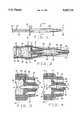
- FIG. 1is a side elevation view of the sheath and syringe of the present invention
- FIG. 2is a partial view, in section, taken in a plane along the line 2--2 in FIG. 1, showing detail of the sheath and syringe of the invention;
- FIG. 3is a partial view, in section, taken in a plane along the line 3--3 of FIG. 2;
- FIG. 4is a partial view, in section, similar to that of FIG. 3 showing the sheath center rod withdrawn from the tapered portion of the syringe bore.
- the syringe 10 of the present inventionis shown assembled in FIG. 1.
- the syringe 10is comprised of a syringe plunger 12, a syringe barrel 14 and a protective sheath 16.
- these basic component partsare all constructed of a resilient, plastic material, for example polyethylene or polypropylene.
- Plunger 12is slidably received within the barrel 14, and sheath 16 is removably attached to the end of barrel 14.
- Plunger 12includes an elongated rod 22 with a finger push tab 24 at one end and a sealing piston 26 at its opposite end (shown in FIG. 2).
- the syringe barrel 14has a cylindrical, tubular configuration with finger flanges 32 at one end and a cannula collar 34 at the axially opposite end of the elongated barrel 14.
- the interior chamber 36 of the barrelhas a cylindrical interior surface dimensioned to receive the plunger piston 26 in sliding, sealing engagement therein.
- the cannula 38is supported in the cannula collar 34 of the syringe.
- the cannula 38has an axial length with opposite proximal 42 and distal 44 ends.
- the proximal end 42is secured within the collar 34 of the syringe barrel 14 by an adhesive 46 or in some other suitable manner.
- the cannula distal end 44 outside the collar 34tapers to a sharpened end, e.g., a point.
- the cannulais constructed of a metal (e.g., stainless steel) and is from about 10 to about 18 (preferably about 16) gauge.
- the cannulahas a cylindrical interior surface 48 that surrounds an interior bore 52 of the syringe, the interior bore 52 extending from the cannula distal end 44 through the cannula 38 and the collar 34 to the syringe barrel interior chamber 36.
- the segment of the interior bore 52 that extends through the cannula between its distal 44 and proximal 42 endshas a constant interior diameter.
- the segment of the interior bore 52 that extends from the cannula proximal end 42 through the syringe collar 34 to the barrel interior chamber 36tapers as it extends toward the interior chamber.
- This segment of the interior bore 52is surrounded by an interior surface 54 of the syringe barrel collar 34 having a frustoconical configuration. As in FIGS.
- the segment of the interior bore 52 surrounded by the collar interior surface 54begins with an interior diameter substantially equal to that of the cannula interior surface 48 and tapers to an interior diameter less than that of the cannula interior surface as it extends toward the interior chamber 36 of the syringe barrel from the cannula proximal end 42.
- the sheath 16has an axial length with a hollow interior 62.
- a collar 64surrounds an opening to the interior at one end of the sheath and the opposite end 66 of the sheath is closed.
- the collar 64is configured to be releasably attached around the exterior of the syringe barrel 14 adjacent the collar 34, as in FIG. 2.
- the sheath interior 62is sufficiently large to receive the syringe barrel collar 34 and the cannula 38 therein with the collar 64 removably attached over the exterior of the syringe barrel 14 as shown in FIG. 2.
- a center rod 68is affixed to the sheath 16 within its interior 62.
- the center rod 68has an elongated configuration with a distal end 72 secured to the closed end 66 of the sheath and a proximal end 74 positioned outside the sheath interior 62. As seen in FIG. 2, the length of the rod is sufficient to project the rod proximal end 74 completely through the tapered segment of the interior bore 52 within the syringe barrel collar 34 with the sheath 16 attached to the exterior of the syringe barrel.
- the center rod 68has a cylindrical configuration with a constant diameter along its entire length.
- the diameter of the center rod 68is less than the interior diameter of the segment of the interior bore 52 surrounded by the cannula interior surface 48, but is larger than the interior diameter of at least a portion of the segment of the interior bore 52 surrounded by the interior surface 54 of the syringe barrel collar 34.
- a portion of the rod adjacent its proxmial end 74may be tapered slightly as shown in phantom lines in FIG. 3.
- the taperis provided to assist in insertion of the rod proximal end 74 through the interior bore 52 at the cannula distal end 44 when attaching the sheath to the syringe barrel exterior.
- Such a taper of the end of rod 68is especially advantageous if the diameter of the first segment of the bore decreases abruptly, rather than tapering, to the smaller diameter of the second bore segment.
- the entire center rod 68may be constructed of a material that is not resilient, for example a metal.
- the tapered segment of the collar interior surfaceis replaced by a necked down portion of the interior bore where the bore diameter changes abruptly from the first diameter to the second diameter at an annular wall that is perpendicular to the bore center axis.
- This embodimentis illustrated in dashed lines in FIG. 4.
- the tapered rod end 74engages against the inner peripheral edge of the annular wall, thus producing a seal within the bore.
- the boreis sealed from the barrel interior chamber 36 preventing any substance 76 contained within the chamber from potentially blocking the interior bore 52.
Landscapes
- Health & Medical Sciences (AREA)
- Hematology (AREA)
- Engineering & Computer Science (AREA)
- Anesthesiology (AREA)
- Biomedical Technology (AREA)
- Heart & Thoracic Surgery (AREA)
- Vascular Medicine (AREA)
- Life Sciences & Earth Sciences (AREA)
- Animal Behavior & Ethology (AREA)
- General Health & Medical Sciences (AREA)
- Public Health (AREA)
- Veterinary Medicine (AREA)
- Infusion, Injection, And Reservoir Apparatuses (AREA)
- Materials For Medical Uses (AREA)
Abstract
Description
Claims (21)
Priority Applications (13)
| Application Number | Priority Date | Filing Date | Title |
|---|---|---|---|
| US08/283,324US5433711A (en) | 1994-08-01 | 1994-08-01 | Syringe with cannula-protecting sheath and sealing center rod |
| JP8506515AJPH10504740A (en) | 1994-08-01 | 1995-07-14 | Syringe including a sheath protecting the cannula and a sealed center rod |
| EP95927141AEP1024849B1 (en) | 1994-08-01 | 1995-07-14 | Syringe with cannula-protecting sheath and sealing center rod |
| CN95195370ACN1105583C (en) | 1994-08-01 | 1995-07-14 | Syringe with cannula-protecting sheath and sealing center rod |
| BR9508484ABR9508484A (en) | 1994-08-01 | 1995-07-14 | Syringe with cannula protective coating and central sealing rod |
| PCT/US1995/008719WO1996004031A1 (en) | 1994-08-01 | 1995-07-14 | Syringe with cannula-protecting sheath and sealing center rod |
| AT95927141TATE250950T1 (en) | 1994-08-01 | 1995-07-14 | SYRINGE WITH A CANNULA PROTECTIVE COVER AND SEALED CENTRAL ROD |
| MX9700836AMX9700836A (en) | 1994-08-01 | 1995-07-14 | Syringe with cannula-protecting sheath and sealing center rod. |
| AU31261/95AAU3126195A (en) | 1994-08-01 | 1995-07-14 | Syringe with cannula-protecting sheath and sealing center rod |
| HK98102647.6AHK1003504B (en) | 1994-08-01 | 1995-07-14 | Syringe with cannula-protecting sheath and sealing center rod |
| DE69531879TDE69531879D1 (en) | 1994-08-01 | 1995-07-14 | SYRINGE WITH A CANNULA PROTECTIVE COVER AND SEALED CENTRAL ROD |
| KR1019970700659AKR100378716B1 (en) | 1994-08-01 | 1995-07-14 | Syringe with cannula protective cover and center of seal |
| CA002196316ACA2196316C (en) | 1994-08-01 | 1995-07-14 | Syringe with cannula-protecting sheath and sealing center rod |
Applications Claiming Priority (1)
| Application Number | Priority Date | Filing Date | Title |
|---|---|---|---|
| US08/283,324US5433711A (en) | 1994-08-01 | 1994-08-01 | Syringe with cannula-protecting sheath and sealing center rod |
Publications (1)
| Publication Number | Publication Date |
|---|---|
| US5433711Atrue US5433711A (en) | 1995-07-18 |
Family
ID=23085480
Family Applications (1)
| Application Number | Title | Priority Date | Filing Date |
|---|---|---|---|
| US08/283,324Expired - LifetimeUS5433711A (en) | 1994-08-01 | 1994-08-01 | Syringe with cannula-protecting sheath and sealing center rod |
Country Status (11)
| Country | Link |
|---|---|
| US (1) | US5433711A (en) |
| EP (1) | EP1024849B1 (en) |
| JP (1) | JPH10504740A (en) |
| KR (1) | KR100378716B1 (en) |
| CN (1) | CN1105583C (en) |
| AT (1) | ATE250950T1 (en) |
| AU (1) | AU3126195A (en) |
| BR (1) | BR9508484A (en) |
| DE (1) | DE69531879D1 (en) |
| MX (1) | MX9700836A (en) |
| WO (1) | WO1996004031A1 (en) |
Cited By (21)
| Publication number | Priority date | Publication date | Assignee | Title |
|---|---|---|---|---|
| US5695463A (en)* | 1994-09-27 | 1997-12-09 | Societe De Conseils De Recherches Et D'applications | Safety injection device |
| US5776107A (en)* | 1996-12-31 | 1998-07-07 | Delab | Injection device |
| US5919169A (en)* | 1997-06-23 | 1999-07-06 | Grams; Guenter | Cannula lock and seal mechanism |
| US5951520A (en)* | 1996-12-19 | 1999-09-14 | Bio-Plexus, Inc. | Self-blunting needle medical devices and methods of manufacture thereof |
| US6599276B1 (en)* | 2000-02-09 | 2003-07-29 | Process Detectable Needles, Inc. | Detectable stainless steel needles for meat packing |
| US7445612B2 (en) | 1996-12-31 | 2008-11-04 | Société de Conseils de Recherches et d'Applications Scientifiques, S.A.S. | Safety injection device for a liquid or semi-solid composition |
| US20090216201A1 (en)* | 2007-11-21 | 2009-08-27 | Becton, Dickinson And Company | Safety Needle Guard |
| USD641078S1 (en) | 2008-12-29 | 2011-07-05 | Ucb Pharma, S.A. | Medical syringe with needle tip cap |
| US8057431B2 (en) | 2006-12-21 | 2011-11-15 | B. Braun Melsungen Ag | Hinged cap for needle device |
| USD660958S1 (en) | 2009-07-20 | 2012-05-29 | Ucb Pharma, S.A. | Device for administering medication |
| US8579866B2 (en) | 2008-01-11 | 2013-11-12 | Ucb Pharma, S.A. | Systems and methods for administering medication |
| US8945067B2 (en) | 2008-07-18 | 2015-02-03 | Ucb Pharma, S.A. | Systems for administering medication |
| GB2516899A (en)* | 2013-08-05 | 2015-02-11 | Mohamed Salim Dean | Safety hypodermic syringe |
| US9278180B2 (en) | 2007-11-21 | 2016-03-08 | Becton, Dickinson And Company | Needle safety device |
| US20160151089A1 (en)* | 2014-12-02 | 2016-06-02 | Merit Medical Systems, Inc. | Distally oriented needle obturator |
| WO2018112308A1 (en)* | 2016-12-16 | 2018-06-21 | Ventana Medical Systems, Inc. | Dispenser nozzle residue mitigation |
| US10029049B2 (en) | 2015-03-19 | 2018-07-24 | B. Braun Melsungen Ag | Hinged shield assemblies and related methods |
| US10639430B2 (en) | 2010-11-22 | 2020-05-05 | B. Braun Melsungen Ag | Hinged shield assemblies and related methods |
| US11191888B1 (en)* | 2020-05-18 | 2021-12-07 | Agitated Solutions Inc. | Syringe-based microbubble generator |
| EP4284462A4 (en)* | 2021-01-26 | 2025-02-19 | Agitated Solutions Inc. | SYRINGE-BASED MICRO BUBBLE GENERATOR WITH AERATOR |
| US12357761B2 (en) | 2016-12-28 | 2025-07-15 | Sanbio, Inc. | Cell delivery system and methods of operation thereof |
Families Citing this family (1)
| Publication number | Priority date | Publication date | Assignee | Title |
|---|---|---|---|---|
| CA3149489A1 (en)* | 2019-08-06 | 2021-02-11 | Microvention, Inc. | Syringe |
Citations (26)
| Publication number | Priority date | Publication date | Assignee | Title |
|---|---|---|---|---|
| GB109041A (en)* | 1916-08-19 | 1917-10-30 | Auxiliaire De Brevets Soc | Improvements in Hypodermic Syringes. |
| GB109040A (en)* | 1915-11-23 | 1917-10-30 | Medica S A Fabrique D Instr De | Improvements in Hypodermic Syringes. |
| US1279530A (en)* | 1916-10-18 | 1918-09-24 | William Fitting | Hypodermic syringe and the like. |
| GB129650A (en)* | 1918-07-12 | 1920-10-11 | Hoffmann La Roche | Contrivance for Fastening a Protecting Hood on Injection Syringes. |
| US1711352A (en)* | 1928-01-12 | 1929-04-30 | George A Jeffreys | Tracheal-swab syringe |
| FR776968A (en)* | 1933-10-26 | 1935-02-08 | Hypodermic injection device | |
| DE639855C (en)* | 1934-04-13 | 1936-12-14 | Erich Buddeberg | Injection ampoule |
| US2219301A (en)* | 1939-04-15 | 1940-10-29 | Squibb & Sons Inc | Hypodermic unit |
| US2578813A (en)* | 1947-12-20 | 1951-12-18 | Kollsman Paul | Device for hypodermic injections |
| FR1003347A (en)* | 1949-12-15 | 1952-03-17 | Advanced ampoule for hypodermic injections | |
| DE869411C (en)* | 1951-12-21 | 1953-06-25 | Eugen Dr Gaessler | Squeezable ampoule |
| US2668534A (en)* | 1952-06-03 | 1954-02-09 | Pm Ind Inc | Plastic injection device |
| GB727348A (en)* | 1952-01-24 | 1955-03-30 | A M Bickford And Sons Ltd | An improved container syringe and method of filling same |
| FR63246E (en)* | 1952-08-11 | 1955-09-12 | Advanced ampoule for hypodermic injections | |
| US2742041A (en)* | 1953-03-19 | 1956-04-17 | Giaocchino Lipari | Combination pre-sterilized syringe and container |
| US2757671A (en)* | 1952-02-05 | 1956-08-07 | Unicura N V | Container-dispensers |
| GB979124A (en)* | 1960-06-10 | 1965-01-01 | Int Treuhand A G | An injection or hypodermic syringe |
| CH412204A (en)* | 1963-03-15 | 1966-04-30 | Byk Gulden Lomberg Chem Fab | Piping pack |
| GB1150196A (en)* | 1966-10-24 | 1969-04-30 | Ida Solowey | Combination Hypodermic Needle Blocker and Needle Sheath. |
| US3559645A (en)* | 1968-07-01 | 1971-02-02 | Kathryn C Schaller | Disposable syringe |
| FR2082127A5 (en)* | 1970-03-04 | 1971-12-10 | Idees | Needle-carrying stopper - for syringes |
| GB1575551A (en)* | 1976-04-21 | 1980-09-24 | Leer Koninklijke Emballage | Container with a sealed outflow channel |
| GB2195537A (en)* | 1984-11-21 | 1988-04-13 | Ewald Pickhard | Injection syringe |
| WO1991010423A1 (en)* | 1990-01-10 | 1991-07-25 | Alza Corporation | Long-term delivery device including loading dose |
| EP0510575A1 (en)* | 1991-04-22 | 1992-10-28 | Schering Corporation | Mastitis infusion system and frangible mastitis cannula closure therefor |
| US5199952A (en)* | 1991-04-09 | 1993-04-06 | Morf, Inc. | Bird injection system |
Family Cites Families (2)
| Publication number | Priority date | Publication date | Assignee | Title |
|---|---|---|---|---|
| BE509197A (en)* | 1951-07-09 | |||
| CH301964A (en)* | 1952-07-18 | 1954-09-30 | Unitubo S A | Hypodermic syringe. |
- 1994
- 1994-08-01USUS08/283,324patent/US5433711A/ennot_activeExpired - Lifetime
- 1995
- 1995-07-14KRKR1019970700659Apatent/KR100378716B1/ennot_activeExpired - Lifetime
- 1995-07-14JPJP8506515Apatent/JPH10504740A/ennot_activeCeased
- 1995-07-14CNCN95195370Apatent/CN1105583C/ennot_activeExpired - Lifetime
- 1995-07-14WOPCT/US1995/008719patent/WO1996004031A1/enactiveIP Right Grant
- 1995-07-14MXMX9700836Apatent/MX9700836A/enunknown
- 1995-07-14AUAU31261/95Apatent/AU3126195A/ennot_activeAbandoned
- 1995-07-14DEDE69531879Tpatent/DE69531879D1/ennot_activeExpired - Lifetime
- 1995-07-14EPEP95927141Apatent/EP1024849B1/ennot_activeExpired - Lifetime
- 1995-07-14ATAT95927141Tpatent/ATE250950T1/enactive
- 1995-07-14BRBR9508484Apatent/BR9508484A/ennot_activeIP Right Cessation
Patent Citations (26)
| Publication number | Priority date | Publication date | Assignee | Title |
|---|---|---|---|---|
| GB109040A (en)* | 1915-11-23 | 1917-10-30 | Medica S A Fabrique D Instr De | Improvements in Hypodermic Syringes. |
| GB109041A (en)* | 1916-08-19 | 1917-10-30 | Auxiliaire De Brevets Soc | Improvements in Hypodermic Syringes. |
| US1279530A (en)* | 1916-10-18 | 1918-09-24 | William Fitting | Hypodermic syringe and the like. |
| GB129650A (en)* | 1918-07-12 | 1920-10-11 | Hoffmann La Roche | Contrivance for Fastening a Protecting Hood on Injection Syringes. |
| US1711352A (en)* | 1928-01-12 | 1929-04-30 | George A Jeffreys | Tracheal-swab syringe |
| FR776968A (en)* | 1933-10-26 | 1935-02-08 | Hypodermic injection device | |
| DE639855C (en)* | 1934-04-13 | 1936-12-14 | Erich Buddeberg | Injection ampoule |
| US2219301A (en)* | 1939-04-15 | 1940-10-29 | Squibb & Sons Inc | Hypodermic unit |
| US2578813A (en)* | 1947-12-20 | 1951-12-18 | Kollsman Paul | Device for hypodermic injections |
| FR1003347A (en)* | 1949-12-15 | 1952-03-17 | Advanced ampoule for hypodermic injections | |
| DE869411C (en)* | 1951-12-21 | 1953-06-25 | Eugen Dr Gaessler | Squeezable ampoule |
| GB727348A (en)* | 1952-01-24 | 1955-03-30 | A M Bickford And Sons Ltd | An improved container syringe and method of filling same |
| US2757671A (en)* | 1952-02-05 | 1956-08-07 | Unicura N V | Container-dispensers |
| US2668534A (en)* | 1952-06-03 | 1954-02-09 | Pm Ind Inc | Plastic injection device |
| FR63246E (en)* | 1952-08-11 | 1955-09-12 | Advanced ampoule for hypodermic injections | |
| US2742041A (en)* | 1953-03-19 | 1956-04-17 | Giaocchino Lipari | Combination pre-sterilized syringe and container |
| GB979124A (en)* | 1960-06-10 | 1965-01-01 | Int Treuhand A G | An injection or hypodermic syringe |
| CH412204A (en)* | 1963-03-15 | 1966-04-30 | Byk Gulden Lomberg Chem Fab | Piping pack |
| GB1150196A (en)* | 1966-10-24 | 1969-04-30 | Ida Solowey | Combination Hypodermic Needle Blocker and Needle Sheath. |
| US3559645A (en)* | 1968-07-01 | 1971-02-02 | Kathryn C Schaller | Disposable syringe |
| FR2082127A5 (en)* | 1970-03-04 | 1971-12-10 | Idees | Needle-carrying stopper - for syringes |
| GB1575551A (en)* | 1976-04-21 | 1980-09-24 | Leer Koninklijke Emballage | Container with a sealed outflow channel |
| GB2195537A (en)* | 1984-11-21 | 1988-04-13 | Ewald Pickhard | Injection syringe |
| WO1991010423A1 (en)* | 1990-01-10 | 1991-07-25 | Alza Corporation | Long-term delivery device including loading dose |
| US5199952A (en)* | 1991-04-09 | 1993-04-06 | Morf, Inc. | Bird injection system |
| EP0510575A1 (en)* | 1991-04-22 | 1992-10-28 | Schering Corporation | Mastitis infusion system and frangible mastitis cannula closure therefor |
Cited By (40)
| Publication number | Priority date | Publication date | Assignee | Title |
|---|---|---|---|---|
| US5695463A (en)* | 1994-09-27 | 1997-12-09 | Societe De Conseils De Recherches Et D'applications | Safety injection device |
| US6896670B2 (en) | 1994-09-27 | 2005-05-24 | Societe De Conseils De Recherches Et D'applications Scientifiques, S.A.S. | Safety injection device |
| US20030114799A1 (en)* | 1994-09-27 | 2003-06-19 | Cheikh Roland Cherif | Safety injection device |
| US6254574B1 (en) | 1996-12-19 | 2001-07-03 | Bio-Plexus, Inc. | Self-blunting needle medical devices and methods of manufacture thereof |
| US5951520A (en)* | 1996-12-19 | 1999-09-14 | Bio-Plexus, Inc. | Self-blunting needle medical devices and methods of manufacture thereof |
| US6213983B1 (en) | 1996-12-31 | 2001-04-10 | Delab | Injection device |
| US7445612B2 (en) | 1996-12-31 | 2008-11-04 | Société de Conseils de Recherches et d'Applications Scientifiques, S.A.S. | Safety injection device for a liquid or semi-solid composition |
| US5776107A (en)* | 1996-12-31 | 1998-07-07 | Delab | Injection device |
| US5919169A (en)* | 1997-06-23 | 1999-07-06 | Grams; Guenter | Cannula lock and seal mechanism |
| USRE43453E1 (en)* | 2000-02-09 | 2012-06-05 | Neogen Corporation | Detectable stainless steel needles for meat packing |
| US6599276B1 (en)* | 2000-02-09 | 2003-07-29 | Process Detectable Needles, Inc. | Detectable stainless steel needles for meat packing |
| US8057431B2 (en) | 2006-12-21 | 2011-11-15 | B. Braun Melsungen Ag | Hinged cap for needle device |
| US8715231B2 (en) | 2006-12-21 | 2014-05-06 | B. Braun Melsungen Ag | Hinged cap for needle device |
| US20090216201A1 (en)* | 2007-11-21 | 2009-08-27 | Becton, Dickinson And Company | Safety Needle Guard |
| US9278180B2 (en) | 2007-11-21 | 2016-03-08 | Becton, Dickinson And Company | Needle safety device |
| US8298180B2 (en) | 2007-11-21 | 2012-10-30 | Becton, Dickinson And Company | Safety needle guard |
| US8579866B2 (en) | 2008-01-11 | 2013-11-12 | Ucb Pharma, S.A. | Systems and methods for administering medication |
| US10661023B2 (en) | 2008-01-11 | 2020-05-26 | Ucb Bioparma Sprl | Systems and methods for administering medication |
| US9901686B2 (en) | 2008-01-11 | 2018-02-27 | Ucb Biopharma Sprl | Systems and methods for administering medication |
| US8945067B2 (en) | 2008-07-18 | 2015-02-03 | Ucb Pharma, S.A. | Systems for administering medication |
| US9333305B2 (en) | 2008-07-18 | 2016-05-10 | Ucb Biopharma Sprl | Systems for automatically administering medication |
| USD653336S1 (en) | 2008-12-29 | 2012-01-31 | Ucb Pharma, S.A. | Needle tip cap connector |
| USD649632S1 (en) | 2008-12-29 | 2011-11-29 | Ucb Pharma, S.A. | Handle for a medication administration device |
| USD641078S1 (en) | 2008-12-29 | 2011-07-05 | Ucb Pharma, S.A. | Medical syringe with needle tip cap |
| USD661389S1 (en) | 2008-12-29 | 2012-06-05 | Ucb Pharma, S.A. | Syringe handle for a medication administration device |
| USD660958S1 (en) | 2009-07-20 | 2012-05-29 | Ucb Pharma, S.A. | Device for administering medication |
| USD676552S1 (en) | 2009-07-20 | 2013-02-19 | Ucb Pharma, S.A. | Needle cap for a medication administration device |
| US10639430B2 (en) | 2010-11-22 | 2020-05-05 | B. Braun Melsungen Ag | Hinged shield assemblies and related methods |
| GB2516899A (en)* | 2013-08-05 | 2015-02-11 | Mohamed Salim Dean | Safety hypodermic syringe |
| US20160151089A1 (en)* | 2014-12-02 | 2016-06-02 | Merit Medical Systems, Inc. | Distally oriented needle obturator |
| US10029049B2 (en) | 2015-03-19 | 2018-07-24 | B. Braun Melsungen Ag | Hinged shield assemblies and related methods |
| US10617830B2 (en) | 2015-03-19 | 2020-04-14 | B. Braun Melsungen Ag | Hinged shield assemblies and related methods |
| WO2018112308A1 (en)* | 2016-12-16 | 2018-06-21 | Ventana Medical Systems, Inc. | Dispenser nozzle residue mitigation |
| US11561234B2 (en) | 2016-12-16 | 2023-01-24 | Ventana Medical Systems, Inc. | Dispenser nozzle residue mitigation |
| US11906535B2 (en) | 2016-12-16 | 2024-02-20 | Ventana Medic Systems, Inc. | Dispenser nozzle residue mitigation |
| US12357761B2 (en) | 2016-12-28 | 2025-07-15 | Sanbio, Inc. | Cell delivery system and methods of operation thereof |
| US11191888B1 (en)* | 2020-05-18 | 2021-12-07 | Agitated Solutions Inc. | Syringe-based microbubble generator |
| US20220233760A1 (en)* | 2020-05-18 | 2022-07-28 | Agitated Solutions Inc. | Syringe-based microbubble generator |
| US11951277B2 (en)* | 2020-05-18 | 2024-04-09 | Agitated Solutions Inc. | Syringe-based microbubble generator |
| EP4284462A4 (en)* | 2021-01-26 | 2025-02-19 | Agitated Solutions Inc. | SYRINGE-BASED MICRO BUBBLE GENERATOR WITH AERATOR |
Also Published As
| Publication number | Publication date |
|---|---|
| DE69531879D1 (en) | 2003-11-06 |
| KR100378716B1 (en) | 2003-07-18 |
| ATE250950T1 (en) | 2003-10-15 |
| CN1105583C (en) | 2003-04-16 |
| MX9700836A (en) | 1997-05-31 |
| AU3126195A (en) | 1996-03-04 |
| JPH10504740A (en) | 1998-05-12 |
| EP1024849B1 (en) | 2003-10-01 |
| CN1161003A (en) | 1997-10-01 |
| WO1996004031A1 (en) | 1996-02-15 |
| BR9508484A (en) | 1997-11-25 |
| HK1003504A1 (en) | 1998-10-30 |
| EP1024849A1 (en) | 2000-08-09 |
Similar Documents
| Publication | Publication Date | Title |
|---|---|---|
| US5433711A (en) | Syringe with cannula-protecting sheath and sealing center rod | |
| US5782803A (en) | Low dead space, interchangeable needle syringe | |
| CA1183420A (en) | Automatic injection syringe | |
| JP3083134B2 (en) | Cannula sealed shield assembly | |
| US5713857A (en) | Sequential stopper | |
| EP0588148B1 (en) | Syringe having needle isolation features | |
| US4668223A (en) | Syringe | |
| US5453093A (en) | Disposable dental syringe | |
| EP1225937B1 (en) | Multiple-dose syringe | |
| US5411489A (en) | Pre-filled syringe and pre-filled cartridge having actuating cylinder/plunger rod combination for reducing syringing force | |
| EP1225933B1 (en) | Retractable dental syringe | |
| US2888923A (en) | New ampoule-syringe | |
| HU182036B (en) | Injection syringe as well as needle holder and recipient belonging same | |
| US4990141A (en) | Single-use syringe | |
| CA2206065A1 (en) | Stopper assembly having bypass features for use in a multi-chamber syringe barrel | |
| JP2002515268A (en) | Syringe assembly | |
| US20160144117A1 (en) | Hypodermic syringe that automatically ejects medicament from a needle | |
| US5484413A (en) | Disposable medical syringe with safety protection | |
| US5413564A (en) | Predetermined dosage hypodermic syringe system | |
| US2735430A (en) | huber | |
| WO2021058480A1 (en) | Needle assembly with retractable biostatic plug | |
| CA2196316C (en) | Syringe with cannula-protecting sheath and sealing center rod | |
| HK1003504B (en) | Syringe with cannula-protecting sheath and sealing center rod | |
| MXPA00003873A (en) | Preloadable syringe for automated dispensing device | |
| MXPA97004884A (en) | A reten secuenc |
Legal Events
| Date | Code | Title | Description |
|---|---|---|---|
| AS | Assignment | Owner name:MONSANTO COMPANY, MISSOURI Free format text:ASSIGNMENT OF ASSIGNORS INTEREST;ASSIGNORS:BALABAN, STEPHEN M.;SMITH, JONATHAN PAUL;REEL/FRAME:007116/0396 Effective date:19940729 | |
| STCF | Information on status: patent grant | Free format text:PATENTED CASE | |
| FEPP | Fee payment procedure | Free format text:PAYOR NUMBER ASSIGNED (ORIGINAL EVENT CODE: ASPN); ENTITY STATUS OF PATENT OWNER: LARGE ENTITY | |
| FPAY | Fee payment | Year of fee payment:4 | |
| AS | Assignment | Owner name:MONSANTO TECHNOLOGY LLC, MISSOURI Free format text:ASSIGNMENT OF ASSIGNORS INTEREST;ASSIGNOR:PHARMACIA CORPORATION, FORMERLY KNOWN AS MONSATO COMPANY;REEL/FRAME:012350/0224 Effective date:20010611 Owner name:MONSANTO TECHNOLOGY LLC,MISSOURI Free format text:ASSIGNMENT OF ASSIGNORS INTEREST;ASSIGNOR:PHARMACIA CORPORATION, FORMERLY KNOWN AS MONSATO COMPANY;REEL/FRAME:012350/0224 Effective date:20010611 | |
| FPAY | Fee payment | Year of fee payment:8 | |
| FPAY | Fee payment | Year of fee payment:12 | |
| FEPP | Fee payment procedure | Free format text:PAYOR NUMBER ASSIGNED (ORIGINAL EVENT CODE: ASPN); ENTITY STATUS OF PATENT OWNER: LARGE ENTITY Free format text:PAYER NUMBER DE-ASSIGNED (ORIGINAL EVENT CODE: RMPN); ENTITY STATUS OF PATENT OWNER: LARGE ENTITY | |
| AS | Assignment | Owner name:ELI LILLY AND COMPANY, INDIANA Free format text:ASSIGNMENT OF ASSIGNORS INTEREST;ASSIGNOR:MONSANTO TECHNOLOGY, LLC;REEL/FRAME:021985/0459 Effective date:20080929 |