US5433588A - Peristaltic pump with one piece tubing insert and one piece cover - Google Patents
Peristaltic pump with one piece tubing insert and one piece coverDownload PDFInfo
- Publication number
- US5433588A US5433588AUS08/167,776US16777693AUS5433588AUS 5433588 AUS5433588 AUS 5433588AUS 16777693 AUS16777693 AUS 16777693AUS 5433588 AUS5433588 AUS 5433588A
- Authority
- US
- United States
- Prior art keywords
- cover
- tube
- rotor
- slots
- insert
- Prior art date
- Legal status (The legal status is an assumption and is not a legal conclusion. Google has not performed a legal analysis and makes no representation as to the accuracy of the status listed.)
- Expired - Fee Related
Links
Images


Classifications
- F—MECHANICAL ENGINEERING; LIGHTING; HEATING; WEAPONS; BLASTING
- F04—POSITIVE - DISPLACEMENT MACHINES FOR LIQUIDS; PUMPS FOR LIQUIDS OR ELASTIC FLUIDS
- F04B—POSITIVE-DISPLACEMENT MACHINES FOR LIQUIDS; PUMPS
- F04B43/00—Machines, pumps, or pumping installations having flexible working members
- F04B43/12—Machines, pumps, or pumping installations having flexible working members having peristaltic action
- F04B43/1253—Machines, pumps, or pumping installations having flexible working members having peristaltic action by using two or more rollers as squeezing elements, the rollers moving on an arc of a circle during squeezing
Definitions
- the present inventionrelates to a peristaltic pump and, more particularly, to a peristaltic pump in which the fluid-conveying tube can be easily and rapidly replaced.
- a common type of known peristaltic pumphas a rotatable rotor with a plurality of roller elements, a curved surface approximately concentric to the axis of rotation of the rotor, and a flexible tube which is compressed between the surface and rollers so that fluid is moved through the tube in response to movement of the roller elements relative to the surface.
- a removable coveris usually provided to enclose the tube and rotors in order to avoid insertion of a finger where it might be pinched or otherwise injured, and may have on it the curved surface.
- any peristaltic pump of this typethe tube must be frequently removed from the pump for purposes of sterlization.
- wear and tear on the tube due to continual operational flexing thereofresults in a need to occasionally replace the tube.
- it is relatively time consuming to manually remove or detach all of the screws and clamps and then later insert or reattach themand usually requires a screwdriver or other tools which may not be readily available.
- inserting the new tubecan be relatively tedious and time consuming.
- there is a risk that small parts such as screws or clampsmay be lost or misplaced, making it difficult or impossible to fully and properly reassemble the pump to its original condition.
- one object of the present inventionis to provide a peristaltic pump in which the flexible tube can be easily and rapidly replaced, without any need for tools.
- a peristaltic pumpwhich includes: a first member, an arrangement defining a surface at a predetermined location with respect to the first member, an arrangement supporting a plurality of elements on the first member for movement in succession along a path having a portion which passes near the surface, a second member removably supported on the first member and having an arrangement defining first and second passageways, and a flexible tube having first and second ends secured to the second member so that the first and second passageways respectively communicate with the first and second ends of the tube, the tube extending adjacent the surface and being resiliently compressed between the surface and each of the elements moving along the portion of the path of movement.
- an insert for a peristaltic pumpwhich includes: a member having an arrangement defining first and second passageways, and a flexible tube having first and second ends secured to the member so that the first and second passageways respectively communicate with the first and second ends of the tube.
- Still another form of the present inventioninvolves the provision of a peristaltic pump which includes: a first member and a second member, the first and second members having structure thereon which facilitates a removable support of the second member on the first member, the second member having thereon a surface which is at a predetermined location with respect to the first member when the second member is removably supported on the first member, an arrangement supporting a plurality of elements on the first member for movement in succession along a path having a portion which passes near the surface when the second member is removably supported on the first member, and a flexible tube supported on the first member, the tube extending adjacent the surface and being resiliently compressed between the surface and each of the elements moving along the portion of the path of movement when the second member is removably supported on the first member.
- FIG. 1is an exploded perspective view of a peristaltic pump which is part of a dental apparatus and which embodies the present invention
- FIG. 2is a perspective view of a cover which is an element of the pump of FIG. 1;
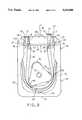
- FIG. 3is an elevational front view of the peristaltic pump of FIG. 1 with a portion of the cover cut away for clarity.
- FIG. 1shows part of a dental apparatus 10, which includes a peristaltic pump mechanism 11 depicted in an exploded condition for clarity.
- the peristaltic pumpis used to produce a flow of water or other irrigating fluid for purposes of rinsing the teeth of a patient.
- the peristaltic pump according to the present inventionis suitable for use in a wide range of other applications.
- the dental apparatus 10includes a front panel member 13 having a front surface 14, the panel member 13 including structure which is a part of the peristaltic pump. More specifically, panel member 13 has near an upper edge thereof two spaced and horizontally forwardly extending projections 16 and 17. Respective horizontal slots 18 and 19 are provided in the projections 16 and 17, each slot opening into the associated projection 16 or 17 from a surface 21 or 22 thereon which faces the other projection, and extending the full length of the projection from the outer end surface 23 or 24 thereof to the front surface 14 on the panel member 13.
- Each projectionhas a recess 26 or 27 in the upper outer end, thereby defining upwardly facing locking surfaces 28 and 29 at the upper ends of the end surfaces 23 and 24.
- the front panel member 13also has intermediate the projections 16 and 17 a horizontally outwardly projecting orientation tab 31, the tab being vertically aligned with the slots 18 and 19 and having a trapezoidal shape so that it tapers progressively in horizontal width in a direction toward its outer end.
- the front panel member 13also has two slots 36 and 37 which each extend vertically downwardly from a location adjacent a respective projection 16 or 17, and has two flanges 38 and 39 which each project into the upper portion of a respective one of the slots 36 and 37 from an outer edge of a side wall of the slot.
- Each of the flanges 38 and 39has a width which is approximately half the width of the associated slot 36 or 37, a thickness which is substantially less than the depth of the slot, and a length which extends approximately half the length of the associated slot from the upper end of the slot.
- a conventional and not-illustrated electric drive motoris mounted on the rear side of the front panel member 13 and has a rotatable drive shaft 43 which extends horizontally through an opening in the front panel member 13.
- the motorcan be selectively actuated in a conventional and not-illustrated manner, for example using a conventional foot switch.
- a rotor 42is non-rotatably mounted on the motor drive shaft 43 and has an approximately triangular shape with apexes which are rounded.
- Three roller elements 46-48(FIGS. 1 and 3) are each supported at a respective apex of the rotor for rotation about a respective horizontal axis extending parallel to the drive shaft 43. As evident from FIG. 3, a peripheral edge portion of each roller element projects outwardly beyond the corresponding rounded apex of the rotor.
- a disposable insert 61includes a plastic plate 63 having an approximately rectangular shape and having in the middle of a longer side thereof an orientation recess 64 of trapezoidal shape.
- the opposite ends of the platecan be respectively slidably inserted into the slots 18 and 19 in the projections 16 and 17, the orientation tab 31 engaging the orientation recess 64 to ensure that plate 63 is not inserted with an inverted orientation, and the trapezoidal shape of tab 31 and recess 64 ensuring that there is no friction or interference between them as the plate 63 is inserted or removed.
- the plastic plate 63has two spaced integral cylindrical projections 67 and 68 extending downwardly from an underside thereof.
- a further projection 71 with circumferential ribsprojects upwardly from an upper side thereof and is coaxial with the projection 67, and a further cylindrical projection 72 extends upwardly from the upper side of plate 63 coaxial with projection 68, the projection 72 having at its upper end a connection flange 73.
- a passageway 76extends centrally through projections 71 and 67 and plate 63, and a passageway 77 extends centrally through projections 68 and 72 and plate 63.
- the plate 63 and projections 67, 68, 71 and 72are all respective portions of a single integral plastic part made by injection molding techniques.
- the disposable insert 61also includes a flexible plastic tube 81, the cylindrical projections 67 and 68 on the underside of plate 63 each extending into the central opening through the tube at a respective end 82 or 83 of the tube, so that the passageways 76 and 77 are each in fluid communication with the central opening through the tube.
- the ends of the tubeare preferably secured to the projections 67 and 68 by a suitable conventional adhesive, which prevents the ends 82 and 83 of the tube from sliding off the projections 67 and 68 as a result of fluid pressure, and which creates a seal that effectively prevents fluid leakage at either end 82 or 83 of the tube.
- the projections 67 and 68 in FIG. 3are cylindrical, it will be recognized that they could alternatively have circumferential ribs or hose barbs similar to those on the projection 71, that a clamp could be used instead of an adhesive, and that the use of an adhesive or clamp is not necessarily essential.
- the pump 11also includes a cover member 91, which in the preferred embodiment is a single integral part made of injection-molded plastic.
- the cover member 91includes a vertically extending front wall 92 of approximately rectangular shape, a bottom wall 93 extending horizontally rearwardly from the lower end of the front wall 92 and two vertical sidewalls 96 and 97 which each extend rearwardly from a respective side of the front wall 92.
- the upper ends 98 and 99 of the sidewalls 96 and 97are vertically lower than the upper end 100 of front wall 92.
- Each of the sidewalls 96 and 97has near its upper rear end an L-shaped flange 101 or 102, each of which includes a leg 103 or 104 projecting rearwardly from tire upper end of a respective sidewall 96 or 97, and a further leg 106 or 107 projecting sidewardly from the outer end of leg 103 or 104.
- a locking rib 111 and a reinforcing rib 112which extends downwardly from the center of the locking rib 111, the ribs 111 and 112 together forming approximately a T-shape.
- the locking rib 111has on a rear side thereof an upwardly and forwardly inclined surface 115, and has on opposite sides of the reinforcing rib 112 respective downwardly facing locking surfaces 113 and 114.
- a U-shaped wall 116projects forwardly from the front wall 92 between the sidewalls 96 and 97, and has upper ends 117 and 118 which are each secured to a respective sidewall 96 or 97.
- a short connecting wall 119extends vertically between the bottom wall 93 and the lowermost portion of the U-shaped wall 116.
- the U-shaped wall 116has on its upper side an upwardly facing curved surface 121 of generally arcuate shape.
- the L-shaped flanges 101 and 102 on the cover member 91are inserted into the lower ends of the slots 36 and 37 at a point below the flanges 38 and 39, and then the cover member 91 is moved upwardly so that the sidewardly projecting legs 106 and 107 slide behind the flanges 38 and 39, until the upper ends 98 and 99 of the sidewalls 96 and 97 are adjacent the underside of the projections 16 and 17.
- the inclined surface 115 on locking rib 111engages the lower forward corners of the projections 16 and 17 and causes the upper portion of the front wall 92 of cover member 91 to flex forwardly, so that the locking rib 111 slides over the end surfaces 23 and 24 of the projections 16 and 17.
- the locking rob 111clears the ends of the projections 16 and 17 so that the resilience of the front wall 92 moves the locking rib 111 rearwardly to a position over the locking surfaces 28 and 29 on the projections 16 and 17. Consequently, the locking surfaces 113 and 114 on the cover engage the locking surfaces 28 and 29 on the projections in order to prevent downward movement of the cover.
- the upper end portion of the front wall 92 of cover member 91is manually flexed forwardly in order to disengage the locking surfaces 113 and 114 on the locking rib 111 from the locking surfaces 28 and 29 on the projections 16 and 17, and then the cover member 91 is moved downwardly until the L-shaped flanges 101 and 102 reach the bottoms of slots 36 and 37, after which the cover member 92 is moved forwardly to withdraw the flanges 101 and 102 from the slots.
- FIG. 3shows the cover member 91 in its mounted condition.
- the upwardly facing curved surface 121is spaced from and faces the drive shaft 43 of the motor substantially concentric thereto.
- the flexible tube 81has its central portion extending adjacent the surface 121.
- the tubeis pinched between the surface 121 and the roller elements 46-48 on the rotor 42 as the rotor 42 rotates, so that fluid is conveyed through the tube 81.
- the resilience of the tube acting on the surface 121tends to urge the cover member 91 downwardly, but downward movement is limited by engagement of the locking surfaces 28 and 29 with locking surfaces 113 and 114. In other words, cooperation between the locking surfaces 28 and 29 and locking surfaces 113 and 114 determines the position of the curved surface 121 relative to the motor shaft 43 and rotor 42.
- a dentistpresses a not illustrated foot switch to selectively energize the motor and effect rotation of shaft 43 and rotor 42, which causes the roller elements 46-48 to successively move along a path of movement which includes an arcuate portion extending adjacent the curved surface 121, the compression of the tube 81 between the surface 121 and the moving roller elements 46-48 causing fluid to be conveyed through the tube 81.
- an operatorfirst removes the cover member 91 in the manner described above, by manually flexing the upper end of front wall 92 forwardly and then moving the cover member 91 downwardly and then forwardly.
- the insert member 61can then be removed by sliding the plate member 63 forwardly out of the slots 18 and 19, the tube 81 being removed with plate 63.
- an identical replacement insert 61is slid into the slots 18 and 19 with the recess 64 facing the tab 31 so that tab 31 moves into recess 64.
- the tab 31would engage the side of the plate 63 opposite from the recess 64, thereby preventing the plate 63 from sliding fully into the slots 18 and 19. A portion of the plate 63 would then project outwardly beyond the end surfaces 23 and 24 on the projections 16 and 17.
- the tube 81is manually positioned so that it extends around the rotor 42. Then, the cover member 91 is reattached the manner already described above.
Landscapes
- Engineering & Computer Science (AREA)
- Mechanical Engineering (AREA)
- General Engineering & Computer Science (AREA)
- Reciprocating Pumps (AREA)
Abstract
Description
Claims (23)
Priority Applications (1)
| Application Number | Priority Date | Filing Date | Title |
|---|---|---|---|
| US08/167,776US5433588A (en) | 1993-12-15 | 1993-12-15 | Peristaltic pump with one piece tubing insert and one piece cover |
Applications Claiming Priority (1)
| Application Number | Priority Date | Filing Date | Title |
|---|---|---|---|
| US08/167,776US5433588A (en) | 1993-12-15 | 1993-12-15 | Peristaltic pump with one piece tubing insert and one piece cover |
Publications (1)
| Publication Number | Publication Date |
|---|---|
| US5433588Atrue US5433588A (en) | 1995-07-18 |
Family
ID=22608781
Family Applications (1)
| Application Number | Title | Priority Date | Filing Date |
|---|---|---|---|
| US08/167,776Expired - Fee RelatedUS5433588A (en) | 1993-12-15 | 1993-12-15 | Peristaltic pump with one piece tubing insert and one piece cover |
Country Status (1)
| Country | Link |
|---|---|
| US (1) | US5433588A (en) |
Cited By (76)
| Publication number | Priority date | Publication date | Assignee | Title |
|---|---|---|---|---|
| US5533877A (en)* | 1994-02-16 | 1996-07-09 | Stockert Instrumente Gmbh | Hose fastening arrangement for roller pumps |
| WO1997005386A1 (en)* | 1995-07-27 | 1997-02-13 | Ognier Jean Francois | Peristaltic pump |
| US5792167A (en)* | 1996-09-13 | 1998-08-11 | Stryker Corporation | Surgical irrigation pump and tool system |
| US5927956A (en)* | 1998-09-01 | 1999-07-27 | Linvatec Corporation | Peristaltic pump tubing system with latching cassette |
| US6106494A (en)* | 1999-03-19 | 2000-08-22 | Stryker Corporation | Self-contained fluid management pump system for surgical procedures |
| US6322330B1 (en)* | 1999-07-28 | 2001-11-27 | Carlisle A. Thomas | Compact peristaltic metering pump |
| US6342061B1 (en) | 1996-09-13 | 2002-01-29 | Barry J. Kauker | Surgical tool with integrated channel for irrigation |
| US6382937B1 (en)* | 1999-10-07 | 2002-05-07 | Phil-chan Rha | Tube pump |
| GB2327901B (en)* | 1997-07-31 | 2002-07-10 | Edward John Crooks | A water cap |
| US6468059B2 (en)* | 1999-12-15 | 2002-10-22 | W.O.M. World Of Medicine Gmbh | Hose cassette for a peristaltic pump |
| US6695803B1 (en) | 1998-10-16 | 2004-02-24 | Mission Medical, Inc. | Blood processing system |
| US20040037724A1 (en)* | 2000-12-12 | 2004-02-26 | Christian Haser | Peristaltic hose pump |
| US6722865B2 (en) | 2001-09-07 | 2004-04-20 | Terumorcardiovascular Systems Corporation | Universal tube clamp assembly |
| US20040179964A1 (en)* | 2003-03-13 | 2004-09-16 | O'mahony John J. | Self-loading peristaltic pump for extracorporeal blood circuit |
| US20040202561A1 (en)* | 2003-04-14 | 2004-10-14 | Stryker Instruments | Surgical irrigation pump and tool system |
| US20050084402A1 (en)* | 2002-02-25 | 2005-04-21 | Jiri Vanek | Peristaltic rotation pump with exact, especially mechanically linear dosage |
| US20050196307A1 (en)* | 2004-03-04 | 2005-09-08 | Cole-Parmer Instrument Company | Peristaltic pump |
| US20050254879A1 (en)* | 2002-06-13 | 2005-11-17 | Gundersen Robert J | Adjustable flow texture sprayer with peristaltic pump |
| US20070140880A1 (en)* | 2005-12-20 | 2007-06-21 | G.H. Stenner & Co., Inc. | Peristaltic pumping mechanism having a removable cover and replaceable tubing, rollers and pumping mechanism |
| US7238164B2 (en) | 2002-07-19 | 2007-07-03 | Baxter International Inc. | Systems, methods and apparatuses for pumping cassette-based therapies |
| US20070183913A1 (en)* | 2006-01-11 | 2007-08-09 | Claude Voyeux | Peristaltic pump including an elastically displaceable locking plate |
| US20070208306A1 (en)* | 2006-03-02 | 2007-09-06 | Sherwood Services Ag | Pumping apparatus with secure loading features |
| US20070208305A1 (en)* | 2006-03-02 | 2007-09-06 | Sherwood Services Ag | Pump set with secure loading features |
| US20070208307A1 (en)* | 2006-03-02 | 2007-09-06 | Sherwood Services Ag | Method for using a pump set having secure loading features |
| US20070212240A1 (en)* | 2004-06-22 | 2007-09-13 | Claude Voyeux | Peristaltic pump with a removable cassette |
| US20070217933A1 (en)* | 2006-02-20 | 2007-09-20 | C/O W.O.M. World Of Medicine Ag | Tubing cassette for a peristaltic pump |
| US20070253833A1 (en)* | 2006-03-02 | 2007-11-01 | Tyco Healthcare Group Lp | Pump Set with Safety Interlock |
| US20070258838A1 (en)* | 2006-05-03 | 2007-11-08 | Sherwood Services Ag | Peristaltic cooling pump system |
| US20080135725A1 (en)* | 2006-12-11 | 2008-06-12 | Tyco Healthcare Group Lp | Pump set and pump with electromagnetic radiation operated interlock |
| US20080167617A1 (en)* | 2007-01-05 | 2008-07-10 | Tyco Heathcare Group Lp | Pump set for administering fluid with secure loading features and manufacture of component therefor |
| US20080175734A1 (en)* | 2007-01-19 | 2008-07-24 | Cole-Parmer Instrument Company | Tube retainer system |
| US20090053085A1 (en)* | 2007-08-24 | 2009-02-26 | Thompson Loren M | Peristalitic pump assembly and method for attaching a cassette thereto |
| US20090129944A1 (en)* | 2007-10-18 | 2009-05-21 | Cole-Palmer Instrument Company | Peristaltic pump |
| US20090214365A1 (en)* | 2008-02-22 | 2009-08-27 | Norman Gerould W | Method and system for loading of tubing into a pumping device |
| EP2116725A2 (en) | 2008-05-09 | 2009-11-11 | Brightwell Dispensers Limited | Peristaltic pump with removable tube |
| USD605286S1 (en) | 2007-01-19 | 2009-12-01 | Cole-Parmer Instrument Company | Tube retainer |
| US7731689B2 (en) | 2007-02-15 | 2010-06-08 | Baxter International Inc. | Dialysis system having inductive heating |
| US20100301071A1 (en)* | 2007-12-05 | 2010-12-02 | Bunn-O-Matic Corporation | Peristaltic pump |
| US7846131B2 (en) | 2005-09-30 | 2010-12-07 | Covidien Ag | Administration feeding set and flow control apparatus with secure loading features |
| US20110021979A1 (en)* | 2006-03-02 | 2011-01-27 | Hudson Joseph A | Enteral Feeding Set and Interlock Device Therefor |
| US20110033318A1 (en)* | 2009-08-05 | 2011-02-10 | Ramirez Jr Emilio A | Single Motor Multiple Pumps |
| US7934912B2 (en) | 2007-09-27 | 2011-05-03 | Curlin Medical Inc | Peristaltic pump assembly with cassette and mounting pin arrangement |
| US20110106004A1 (en)* | 2009-08-12 | 2011-05-05 | Pathway Medical Technologies, Inc. | Systems and methods for operating interventional catheters using a common operating console and adaptive interface components |
| US20110165005A1 (en)* | 2008-07-03 | 2011-07-07 | Bien-Air Holding S.A. | Peristaltic pump and irrigation line |
| US7998115B2 (en)* | 2007-02-15 | 2011-08-16 | Baxter International Inc. | Dialysis system having optical flowrate detection |
| US8062008B2 (en) | 2007-09-27 | 2011-11-22 | Curlin Medical Inc. | Peristaltic pump and removable cassette therefor |
| US8083503B2 (en) | 2007-09-27 | 2011-12-27 | Curlin Medical Inc. | Peristaltic pump assembly and regulator therefor |
| US8154274B2 (en) | 2010-05-11 | 2012-04-10 | Tyco Healthcare Group Lp | Safety interlock |
| US8323231B2 (en) | 2000-02-10 | 2012-12-04 | Baxter International, Inc. | Method and apparatus for monitoring and controlling peritoneal dialysis therapy |
| US8361023B2 (en) | 2007-02-15 | 2013-01-29 | Baxter International Inc. | Dialysis system with efficient battery back-up |
| US20130045121A1 (en)* | 2010-03-01 | 2013-02-21 | Ulrich Gmbh & Co. Kg | Peristaltic Pump |
| US8545435B2 (en) | 2002-01-03 | 2013-10-01 | Baxter International, Inc. | Method and apparatus for providing medical treatment therapy based on calculated demand |
| US8558964B2 (en) | 2007-02-15 | 2013-10-15 | Baxter International Inc. | Dialysis system having display with electromagnetic compliance (“EMC”) seal |
| EP2679255A1 (en)* | 2012-06-26 | 2014-01-01 | Karl Storz GmbH & Co. KG | Pumping system, hose pump and hose cartridge and method for configuring a pumping system |
| US8870812B2 (en) | 2007-02-15 | 2014-10-28 | Baxter International Inc. | Dialysis system having video display with ambient light adjustment |
| US9072540B2 (en) | 2009-08-12 | 2015-07-07 | Boston Scientific Limited | Adaptive tubing cassettes for use in connection with interventional catheter assemblies |
| US10022265B2 (en) | 2015-04-01 | 2018-07-17 | Zoll Circulation, Inc. | Working fluid cassette with hinged plenum or enclosure for interfacing heat exchanger with intravascular temperature management catheter |
| US10077767B2 (en) | 2015-12-24 | 2018-09-18 | Hologic, Inc. | Uterine distension fluid management system with peristaltic pumps |
| US20180305092A1 (en)* | 2017-04-24 | 2018-10-25 | Csp Technologies, Inc. | Slidably openable child resistant container |
| US20190015766A1 (en)* | 2017-07-14 | 2019-01-17 | Vermeer Manufacturing Company | Cyclonic Separation Systems And Hydro Excavation Vacuum Apparatus Incorporating Same |
| US10500088B2 (en) | 2014-02-14 | 2019-12-10 | Zoll Circulation, Inc. | Patient heat exchange system with two and only two fluid loops |
| US10502200B2 (en) | 2014-11-06 | 2019-12-10 | Zoll Circulation, Inc. | Heat exchanges system for patient temperature control with easy loading high performance peristaltic pump |
| US10537465B2 (en) | 2015-03-31 | 2020-01-21 | Zoll Circulation, Inc. | Cold plate design in heat exchanger for intravascular temperature management catheter and/or heat exchange pad |
| US10670006B2 (en)* | 2016-01-22 | 2020-06-02 | Graco Minnesota Inc. | Hose bracket for texture sprayer |
| US10792185B2 (en) | 2014-02-14 | 2020-10-06 | Zoll Circulation, Inc. | Fluid cassette with polymeric membranes and integral inlet and outlet tubes for patient heat exchange system |
| US10828189B2 (en) | 2014-02-07 | 2020-11-10 | Zoll Circulation Inc. | Heat exchange system for patient temperature control with multiple coolant chambers for multiple heat exchange modalities |
| US11035354B2 (en)* | 2016-01-22 | 2021-06-15 | Graco Minnesota Inc. | Hose bracket for texture sprayer |
| US11033424B2 (en) | 2014-02-14 | 2021-06-15 | Zoll Circulation, Inc. | Fluid cassette with tensioned polymeric membranes for patient heat exchange system |
| US20210332617A1 (en)* | 2020-04-22 | 2021-10-28 | Channell Commercial Corporation | Shielded self-latching locking assembly for a utility vault |
| US20210332616A1 (en)* | 2020-04-22 | 2021-10-28 | Channell Commercial Corporation | Shielded self-latching locking assembly for a utility vault |
| US11179516B2 (en) | 2017-06-22 | 2021-11-23 | Baxter International Inc. | Systems and methods for incorporating patient pressure into medical fluid delivery |
| US11185440B2 (en) | 2017-02-02 | 2021-11-30 | Zoll Circulation, Inc. | Devices, systems and methods for endovascular temperature control |
| US20220105005A1 (en)* | 2017-03-24 | 2022-04-07 | Carefusion 303, Inc. | Waste container for automatic drug compounder |
| US11359620B2 (en) | 2015-04-01 | 2022-06-14 | Zoll Circulation, Inc. | Heat exchange system for patient temperature control with easy loading high performance peristaltic pump |
| US11951035B2 (en) | 2017-02-02 | 2024-04-09 | Zoll Circulation, Inc. | Devices, systems and methods for endovascular temperature control |
| US20240328409A1 (en)* | 2023-03-30 | 2024-10-03 | Surpass Industry Co., Ltd. | Tube holding device, tube pump system, and tube installation method |
Citations (15)
| Publication number | Priority date | Publication date | Assignee | Title |
|---|---|---|---|---|
| US4239464A (en)* | 1977-10-14 | 1980-12-16 | Polystan A/S | Blood pump |
| GB2076068A (en)* | 1980-05-16 | 1981-11-25 | Smith & Nephew Ass | Peristaltic fluid-machines |
| US4548553A (en)* | 1984-09-24 | 1985-10-22 | Ferster Reuben I | Peristaltic pump structure |
| US4559040A (en)* | 1984-10-30 | 1985-12-17 | Pancretec, Inc. | Segmented peristaltic pump chamber |
| US4599055A (en)* | 1985-06-25 | 1986-07-08 | Cobe Laboratories, Inc. | Peristaltic pump |
| GB2190145A (en)* | 1986-05-07 | 1987-11-11 | Cobe Lab | Peristaltic pumps |
| US4735558A (en)* | 1986-04-08 | 1988-04-05 | Staar Surgical Company | Peristaltic pump latching mechanism |
| US4824339A (en)* | 1987-08-19 | 1989-04-25 | Cobe Laboratories, Inc. | Peristaltic pump cartridge |
| US4904168A (en)* | 1988-12-28 | 1990-02-27 | United Sonics, Inc. | Cassette assembly for ophthalmic surgery system |
| JPH0326887A (en)* | 1989-06-26 | 1991-02-05 | Sumiyoshi Heavy Ind Co Ltd | Concrete sending pump having tubular rotary device |
| US5017059A (en)* | 1988-05-17 | 1991-05-21 | Patient Solutions, Inc. | Infusion device with disposable elements |
| US5230614A (en)* | 1992-06-03 | 1993-07-27 | Allergan, Inc. | Reduced pulsation tapered ramp pump head |
| US5256041A (en)* | 1993-02-05 | 1993-10-26 | Auto-Chlor System, Incorporated | Peristaltic pump arrangement |
| WO1993022560A1 (en)* | 1992-04-30 | 1993-11-11 | Debiotech S.A. | Cassette-type peristaltique pump provided with an undeceitful assembly |
| EP0569875A1 (en)* | 1992-05-11 | 1993-11-18 | Allweiler AG | Hose pump |
- 1993
- 1993-12-15USUS08/167,776patent/US5433588A/ennot_activeExpired - Fee Related
Patent Citations (16)
| Publication number | Priority date | Publication date | Assignee | Title |
|---|---|---|---|---|
| US4239464A (en)* | 1977-10-14 | 1980-12-16 | Polystan A/S | Blood pump |
| GB2076068A (en)* | 1980-05-16 | 1981-11-25 | Smith & Nephew Ass | Peristaltic fluid-machines |
| US4548553A (en)* | 1984-09-24 | 1985-10-22 | Ferster Reuben I | Peristaltic pump structure |
| US4559040A (en)* | 1984-10-30 | 1985-12-17 | Pancretec, Inc. | Segmented peristaltic pump chamber |
| US4599055A (en)* | 1985-06-25 | 1986-07-08 | Cobe Laboratories, Inc. | Peristaltic pump |
| US4735558A (en)* | 1986-04-08 | 1988-04-05 | Staar Surgical Company | Peristaltic pump latching mechanism |
| GB2190145A (en)* | 1986-05-07 | 1987-11-11 | Cobe Lab | Peristaltic pumps |
| US4909713A (en)* | 1986-05-07 | 1990-03-20 | Cobe Laboratories, Inc. | Peristaltic pump |
| US4824339A (en)* | 1987-08-19 | 1989-04-25 | Cobe Laboratories, Inc. | Peristaltic pump cartridge |
| US5017059A (en)* | 1988-05-17 | 1991-05-21 | Patient Solutions, Inc. | Infusion device with disposable elements |
| US4904168A (en)* | 1988-12-28 | 1990-02-27 | United Sonics, Inc. | Cassette assembly for ophthalmic surgery system |
| JPH0326887A (en)* | 1989-06-26 | 1991-02-05 | Sumiyoshi Heavy Ind Co Ltd | Concrete sending pump having tubular rotary device |
| WO1993022560A1 (en)* | 1992-04-30 | 1993-11-11 | Debiotech S.A. | Cassette-type peristaltique pump provided with an undeceitful assembly |
| EP0569875A1 (en)* | 1992-05-11 | 1993-11-18 | Allweiler AG | Hose pump |
| US5230614A (en)* | 1992-06-03 | 1993-07-27 | Allergan, Inc. | Reduced pulsation tapered ramp pump head |
| US5256041A (en)* | 1993-02-05 | 1993-10-26 | Auto-Chlor System, Incorporated | Peristaltic pump arrangement |
Cited By (143)
| Publication number | Priority date | Publication date | Assignee | Title |
|---|---|---|---|---|
| US5533877A (en)* | 1994-02-16 | 1996-07-09 | Stockert Instrumente Gmbh | Hose fastening arrangement for roller pumps |
| WO1997005386A1 (en)* | 1995-07-27 | 1997-02-13 | Ognier Jean Francois | Peristaltic pump |
| US6062829A (en)* | 1995-07-27 | 2000-05-16 | Ognier; Jean-Francois | Peristaltic pump |
| US6342061B1 (en) | 1996-09-13 | 2002-01-29 | Barry J. Kauker | Surgical tool with integrated channel for irrigation |
| US5792167A (en)* | 1996-09-13 | 1998-08-11 | Stryker Corporation | Surgical irrigation pump and tool system |
| US5928257A (en)* | 1996-09-13 | 1999-07-27 | Stryker Corporation | Surgical irrigation pump and tool system |
| GB2327901B (en)* | 1997-07-31 | 2002-07-10 | Edward John Crooks | A water cap |
| US5927956A (en)* | 1998-09-01 | 1999-07-27 | Linvatec Corporation | Peristaltic pump tubing system with latching cassette |
| US6695803B1 (en) | 1998-10-16 | 2004-02-24 | Mission Medical, Inc. | Blood processing system |
| US6106494A (en)* | 1999-03-19 | 2000-08-22 | Stryker Corporation | Self-contained fluid management pump system for surgical procedures |
| US6602221B1 (en) | 1999-03-19 | 2003-08-05 | Stryker Corporation | Self-contained fluid management pump system for surgical procedures |
| US6322330B1 (en)* | 1999-07-28 | 2001-11-27 | Carlisle A. Thomas | Compact peristaltic metering pump |
| US6382937B1 (en)* | 1999-10-07 | 2002-05-07 | Phil-chan Rha | Tube pump |
| US6468059B2 (en)* | 1999-12-15 | 2002-10-22 | W.O.M. World Of Medicine Gmbh | Hose cassette for a peristaltic pump |
| US9474842B2 (en) | 2000-02-10 | 2016-10-25 | Baxter International Inc. | Method and apparatus for monitoring and controlling peritoneal dialysis therapy |
| US10322224B2 (en) | 2000-02-10 | 2019-06-18 | Baxter International Inc. | Apparatus and method for monitoring and controlling a peritoneal dialysis therapy |
| US8323231B2 (en) | 2000-02-10 | 2012-12-04 | Baxter International, Inc. | Method and apparatus for monitoring and controlling peritoneal dialysis therapy |
| US7287968B2 (en)* | 2000-12-12 | 2007-10-30 | W.O.M. World Of Medicine Ag | Peristalic pump having hinged backing plate |
| US20040037724A1 (en)* | 2000-12-12 | 2004-02-26 | Christian Haser | Peristaltic hose pump |
| US6722865B2 (en) | 2001-09-07 | 2004-04-20 | Terumorcardiovascular Systems Corporation | Universal tube clamp assembly |
| US8545435B2 (en) | 2002-01-03 | 2013-10-01 | Baxter International, Inc. | Method and apparatus for providing medical treatment therapy based on calculated demand |
| US20050084402A1 (en)* | 2002-02-25 | 2005-04-21 | Jiri Vanek | Peristaltic rotation pump with exact, especially mechanically linear dosage |
| US20050254879A1 (en)* | 2002-06-13 | 2005-11-17 | Gundersen Robert J | Adjustable flow texture sprayer with peristaltic pump |
| US7238164B2 (en) | 2002-07-19 | 2007-07-03 | Baxter International Inc. | Systems, methods and apparatuses for pumping cassette-based therapies |
| US7744554B2 (en) | 2002-12-31 | 2010-06-29 | Baxter International Inc. | Cassette alignment and integrity testing for dialysis systems |
| US8206338B2 (en) | 2002-12-31 | 2012-06-26 | Baxter International Inc. | Pumping systems for cassette-based dialysis |
| US20060140799A1 (en)* | 2003-03-13 | 2006-06-29 | Chf Solutions Inc. | Self-loading peristaltic pump for extracorporeal blood circuit |
| US7018182B2 (en)* | 2003-03-13 | 2006-03-28 | Chf Solutions, Inc. | Self-loading peristaltic pump for extracorporeal blood circuit |
| US20040179964A1 (en)* | 2003-03-13 | 2004-09-16 | O'mahony John J. | Self-loading peristaltic pump for extracorporeal blood circuit |
| EP1457677A3 (en)* | 2003-03-13 | 2011-05-25 | CHF Solutions, Inc. | Self-loading peristaltic pump for extracorporeal blood circuit |
| US7547200B2 (en) | 2003-03-13 | 2009-06-16 | Chf Solutions Inc. | Self-loading peristaltic pump for extracorporeal blood circuit |
| US20080015490A1 (en)* | 2003-04-14 | 2008-01-17 | Stryker Corporation | Tube set for use with a surgical irrigation pump and tool system |
| US7238010B2 (en)* | 2003-04-14 | 2007-07-03 | Stryker Corporation | Surgical irrigation pump and tool system |
| US7632079B2 (en)* | 2003-04-14 | 2009-12-15 | Stryker Corporation | Tube set for use with a surgical irrigation pump and tool system |
| US20040202561A1 (en)* | 2003-04-14 | 2004-10-14 | Stryker Instruments | Surgical irrigation pump and tool system |
| US7478999B2 (en) | 2004-03-04 | 2009-01-20 | Cole-Parmer Instrument Company | Peristaltic pump |
| WO2005088130A1 (en)* | 2004-03-04 | 2005-09-22 | Cole-Parmer Instrument Company | Peristaltic pump |
| US20050196307A1 (en)* | 2004-03-04 | 2005-09-08 | Cole-Parmer Instrument Company | Peristaltic pump |
| US20070212240A1 (en)* | 2004-06-22 | 2007-09-13 | Claude Voyeux | Peristaltic pump with a removable cassette |
| US7846131B2 (en) | 2005-09-30 | 2010-12-07 | Covidien Ag | Administration feeding set and flow control apparatus with secure loading features |
| US20070140880A1 (en)* | 2005-12-20 | 2007-06-21 | G.H. Stenner & Co., Inc. | Peristaltic pumping mechanism having a removable cover and replaceable tubing, rollers and pumping mechanism |
| US8182241B2 (en)* | 2005-12-20 | 2012-05-22 | G.H. Stenner & Co., Inc. | Peristaltic pumping mechanism having a removable cover and replaceable tubing, rollers and pumping mechanism |
| US20070183913A1 (en)* | 2006-01-11 | 2007-08-09 | Claude Voyeux | Peristaltic pump including an elastically displaceable locking plate |
| US20070217933A1 (en)* | 2006-02-20 | 2007-09-20 | C/O W.O.M. World Of Medicine Ag | Tubing cassette for a peristaltic pump |
| US8491285B2 (en)* | 2006-02-20 | 2013-07-23 | W.O.M. World Of Medicine Ag | Tubing cassette for a peristaltic pump |
| US20070253833A1 (en)* | 2006-03-02 | 2007-11-01 | Tyco Healthcare Group Lp | Pump Set with Safety Interlock |
| US20100198145A1 (en)* | 2006-03-02 | 2010-08-05 | Tyco Healthcare Group Lp | Pump set with safety interlock |
| US8052643B2 (en) | 2006-03-02 | 2011-11-08 | Tyco Healthcare Group Lp | Enteral feeding set and interlock device therefor |
| US20070208306A1 (en)* | 2006-03-02 | 2007-09-06 | Sherwood Services Ag | Pumping apparatus with secure loading features |
| US9402789B2 (en) | 2006-03-02 | 2016-08-02 | Covidien Ag | Pump set having secure loading features |
| US20100056994A1 (en)* | 2006-03-02 | 2010-03-04 | Covidien Ag | Pumping apparatus with secure loading features |
| US7722573B2 (en) | 2006-03-02 | 2010-05-25 | Covidien Ag | Pumping apparatus with secure loading features |
| US7722562B2 (en) | 2006-03-02 | 2010-05-25 | Tyco Healthcare Group Lp | Pump set with safety interlock |
| US8052642B2 (en) | 2006-03-02 | 2011-11-08 | Covidien Ag | Pumping apparatus with secure loading features |
| US20070208305A1 (en)* | 2006-03-02 | 2007-09-06 | Sherwood Services Ag | Pump set with secure loading features |
| US7758551B2 (en) | 2006-03-02 | 2010-07-20 | Covidien Ag | Pump set with secure loading features |
| US7763005B2 (en) | 2006-03-02 | 2010-07-27 | Covidien Ag | Method for using a pump set having secure loading features |
| US20100198144A1 (en)* | 2006-03-02 | 2010-08-05 | Covidien Ag | Method for using a pump set having secure loading features |
| US8142399B2 (en) | 2006-03-02 | 2012-03-27 | Tyco Healthcare Group Lp | Pump set with safety interlock |
| US7927304B2 (en) | 2006-03-02 | 2011-04-19 | Tyco Healthcare Group Lp | Enteral feeding pump and feeding set therefor |
| US8142404B2 (en) | 2006-03-02 | 2012-03-27 | Covidien Ag | Controller for pumping apparatus |
| US20070208307A1 (en)* | 2006-03-02 | 2007-09-06 | Sherwood Services Ag | Method for using a pump set having secure loading features |
| US20110021979A1 (en)* | 2006-03-02 | 2011-01-27 | Hudson Joseph A | Enteral Feeding Set and Interlock Device Therefor |
| US20070258838A1 (en)* | 2006-05-03 | 2007-11-08 | Sherwood Services Ag | Peristaltic cooling pump system |
| US20090264824A1 (en)* | 2006-12-11 | 2009-10-22 | Tyco Healthcare Group Lp | Pump set and pump with electromagnetic radiation operated interlock |
| US8053721B2 (en) | 2006-12-11 | 2011-11-08 | Tyco Healthcare Group Lp | Pump set and pump with electromagnetic radiation operated interlock |
| US20080135725A1 (en)* | 2006-12-11 | 2008-06-12 | Tyco Healthcare Group Lp | Pump set and pump with electromagnetic radiation operated interlock |
| US7560686B2 (en) | 2006-12-11 | 2009-07-14 | Tyco Healthcare Group Lp | Pump set and pump with electromagnetic radiation operated interlock |
| US8021336B2 (en) | 2007-01-05 | 2011-09-20 | Tyco Healthcare Group Lp | Pump set for administering fluid with secure loading features and manufacture of component therefor |
| US20080167617A1 (en)* | 2007-01-05 | 2008-07-10 | Tyco Heathcare Group Lp | Pump set for administering fluid with secure loading features and manufacture of component therefor |
| US8529511B2 (en) | 2007-01-05 | 2013-09-10 | Covidien Lp | Pump set with secure loading features and related methods therefor |
| US7980835B2 (en) | 2007-01-19 | 2011-07-19 | Cole-Parmer Instrument Company | Tube retainer system for a peristaltic pump |
| USD605286S1 (en) | 2007-01-19 | 2009-12-01 | Cole-Parmer Instrument Company | Tube retainer |
| US20080175734A1 (en)* | 2007-01-19 | 2008-07-24 | Cole-Parmer Instrument Company | Tube retainer system |
| US7998115B2 (en)* | 2007-02-15 | 2011-08-16 | Baxter International Inc. | Dialysis system having optical flowrate detection |
| US7731689B2 (en) | 2007-02-15 | 2010-06-08 | Baxter International Inc. | Dialysis system having inductive heating |
| US9799274B2 (en) | 2007-02-15 | 2017-10-24 | Baxter International Inc. | Method of controlling medical fluid therapy machine brightness |
| US8361023B2 (en) | 2007-02-15 | 2013-01-29 | Baxter International Inc. | Dialysis system with efficient battery back-up |
| US8870812B2 (en) | 2007-02-15 | 2014-10-28 | Baxter International Inc. | Dialysis system having video display with ambient light adjustment |
| US8558964B2 (en) | 2007-02-15 | 2013-10-15 | Baxter International Inc. | Dialysis system having display with electromagnetic compliance (“EMC”) seal |
| US20090053085A1 (en)* | 2007-08-24 | 2009-02-26 | Thompson Loren M | Peristalitic pump assembly and method for attaching a cassette thereto |
| US8062008B2 (en) | 2007-09-27 | 2011-11-22 | Curlin Medical Inc. | Peristaltic pump and removable cassette therefor |
| US8083503B2 (en) | 2007-09-27 | 2011-12-27 | Curlin Medical Inc. | Peristaltic pump assembly and regulator therefor |
| US7934912B2 (en) | 2007-09-27 | 2011-05-03 | Curlin Medical Inc | Peristaltic pump assembly with cassette and mounting pin arrangement |
| US8052399B2 (en) | 2007-10-18 | 2011-11-08 | Cole-Parmer Instrument Company | Peristaltic pump |
| US20090129944A1 (en)* | 2007-10-18 | 2009-05-21 | Cole-Palmer Instrument Company | Peristaltic pump |
| US20100301071A1 (en)* | 2007-12-05 | 2010-12-02 | Bunn-O-Matic Corporation | Peristaltic pump |
| CN101918714A (en)* | 2007-12-05 | 2010-12-15 | 班奥麦迪克公司 | Peristaltic pump |
| US8550310B2 (en)* | 2007-12-05 | 2013-10-08 | Bunn-O-Matic Corporation | Peristaltic pump |
| US10443592B2 (en) | 2008-02-22 | 2019-10-15 | Medtronic Xomed, Inc. | Roller positioning system |
| US20090214365A1 (en)* | 2008-02-22 | 2009-08-27 | Norman Gerould W | Method and system for loading of tubing into a pumping device |
| US8272857B2 (en) | 2008-02-22 | 2012-09-25 | Medtronic Xomed, Inc. | Method and system for loading of tubing into a pumping device |
| US8939740B2 (en) | 2008-02-22 | 2015-01-27 | Medtronic-Xomed, Inc. | Tube positioner |
| EP2116725A3 (en)* | 2008-05-09 | 2012-07-25 | Brightwell Dispensers Limited | Peristaltic pump with removable tube |
| EP2116725A2 (en) | 2008-05-09 | 2009-11-11 | Brightwell Dispensers Limited | Peristaltic pump with removable tube |
| JP2012500653A (en)* | 2008-07-03 | 2012-01-12 | ビエン−エアー ホールディング エスアー | Peristaltic pump and irrigation line |
| US20110165005A1 (en)* | 2008-07-03 | 2011-07-07 | Bien-Air Holding S.A. | Peristaltic pump and irrigation line |
| US8757991B2 (en)* | 2008-07-03 | 2014-06-24 | Bien-Air Holding S.A. | Peristaltic pump and insertable irrigation line with a tube portion having a determined profile |
| US20110033318A1 (en)* | 2009-08-05 | 2011-02-10 | Ramirez Jr Emilio A | Single Motor Multiple Pumps |
| US9072540B2 (en) | 2009-08-12 | 2015-07-07 | Boston Scientific Limited | Adaptive tubing cassettes for use in connection with interventional catheter assemblies |
| US9775964B2 (en) | 2009-08-12 | 2017-10-03 | Boston Scientific Limited | Interventional catheter assemblies, control consoles and adaptive tubing cassettes |
| US8388582B2 (en) | 2009-08-12 | 2013-03-05 | Medrad, Inc. | Systems and methods for operating interventional catheters using a common operating console and adaptive interface components |
| US9925315B2 (en) | 2009-08-12 | 2018-03-27 | Boston Scientific Limited | Adaptive tubing cassettes for use in connection with interventional catheter assemblies |
| US20110106004A1 (en)* | 2009-08-12 | 2011-05-05 | Pathway Medical Technologies, Inc. | Systems and methods for operating interventional catheters using a common operating console and adaptive interface components |
| US10632245B2 (en) | 2009-08-12 | 2020-04-28 | Boston Scientific Limited | Interventional catheter assemblies, control consoles and adaptive tubing cassettes |
| US20130045121A1 (en)* | 2010-03-01 | 2013-02-21 | Ulrich Gmbh & Co. Kg | Peristaltic Pump |
| US8760146B2 (en) | 2010-05-11 | 2014-06-24 | Covidien Lp | Safety interlock |
| US8154274B2 (en) | 2010-05-11 | 2012-04-10 | Tyco Healthcare Group Lp | Safety interlock |
| EP2679255A1 (en)* | 2012-06-26 | 2014-01-01 | Karl Storz GmbH & Co. KG | Pumping system, hose pump and hose cartridge and method for configuring a pumping system |
| US10828189B2 (en) | 2014-02-07 | 2020-11-10 | Zoll Circulation Inc. | Heat exchange system for patient temperature control with multiple coolant chambers for multiple heat exchange modalities |
| US10792185B2 (en) | 2014-02-14 | 2020-10-06 | Zoll Circulation, Inc. | Fluid cassette with polymeric membranes and integral inlet and outlet tubes for patient heat exchange system |
| US10500088B2 (en) | 2014-02-14 | 2019-12-10 | Zoll Circulation, Inc. | Patient heat exchange system with two and only two fluid loops |
| US11033424B2 (en) | 2014-02-14 | 2021-06-15 | Zoll Circulation, Inc. | Fluid cassette with tensioned polymeric membranes for patient heat exchange system |
| US12427055B2 (en) | 2014-02-14 | 2025-09-30 | Zoll Circulation, Inc. | Patient heat exchange system with two and only two fluid loops |
| US11353016B2 (en) | 2014-11-06 | 2022-06-07 | Zoll Circulation, Inc. | Heat exchange system for patient temperature control with easy loading high performance peristaltic pump |
| US10502200B2 (en) | 2014-11-06 | 2019-12-10 | Zoll Circulation, Inc. | Heat exchanges system for patient temperature control with easy loading high performance peristaltic pump |
| US10537465B2 (en) | 2015-03-31 | 2020-01-21 | Zoll Circulation, Inc. | Cold plate design in heat exchanger for intravascular temperature management catheter and/or heat exchange pad |
| US11992434B2 (en) | 2015-03-31 | 2024-05-28 | Zoll Circulation, Inc. | Cold plate design in heat exchanger for intravascular temperature management catheter and/or heat exchange pad |
| US10022265B2 (en) | 2015-04-01 | 2018-07-17 | Zoll Circulation, Inc. | Working fluid cassette with hinged plenum or enclosure for interfacing heat exchanger with intravascular temperature management catheter |
| US11359620B2 (en) | 2015-04-01 | 2022-06-14 | Zoll Circulation, Inc. | Heat exchange system for patient temperature control with easy loading high performance peristaltic pump |
| US12305631B2 (en) | 2015-04-01 | 2025-05-20 | Zoll Circulation, Inc. | Heat exchange system for patient temperature control with easy loading high performance peristaltic pump |
| US11759354B2 (en) | 2015-04-01 | 2023-09-19 | Zoll Circulation, Inc. | Working fluid cassette with hinged plenum or enclosure for interfacing heat exchanger with intravascular temperature management catheter |
| US10077767B2 (en) | 2015-12-24 | 2018-09-18 | Hologic, Inc. | Uterine distension fluid management system with peristaltic pumps |
| US11009021B2 (en) | 2015-12-24 | 2021-05-18 | Hologic, Inc. | Uterine distension fluid management system with peristaltic pumps |
| US12049886B2 (en) | 2015-12-24 | 2024-07-30 | Hologic, Inc. | Uterine distension fluid management system with peristaltic pumps |
| US11525440B2 (en) | 2015-12-24 | 2022-12-13 | Hologic, MA | Uterine distension fluid management system with peristaltic pumps |
| US11035354B2 (en)* | 2016-01-22 | 2021-06-15 | Graco Minnesota Inc. | Hose bracket for texture sprayer |
| US10670006B2 (en)* | 2016-01-22 | 2020-06-02 | Graco Minnesota Inc. | Hose bracket for texture sprayer |
| US11951035B2 (en) | 2017-02-02 | 2024-04-09 | Zoll Circulation, Inc. | Devices, systems and methods for endovascular temperature control |
| US11883323B2 (en) | 2017-02-02 | 2024-01-30 | Zoll Circulation, Inc. | Devices, systems and methods for endovascular temperature control |
| US11185440B2 (en) | 2017-02-02 | 2021-11-30 | Zoll Circulation, Inc. | Devices, systems and methods for endovascular temperature control |
| US20220105005A1 (en)* | 2017-03-24 | 2022-04-07 | Carefusion 303, Inc. | Waste container for automatic drug compounder |
| US11633330B2 (en)* | 2017-03-24 | 2023-04-25 | Carefusion 303, Inc. | Waste container for automatic drug compounder |
| US20180305092A1 (en)* | 2017-04-24 | 2018-10-25 | Csp Technologies, Inc. | Slidably openable child resistant container |
| US10961030B2 (en)* | 2017-04-24 | 2021-03-30 | Csp Technologies, Inc. | Slidably openable child resistant container |
| US11179516B2 (en) | 2017-06-22 | 2021-11-23 | Baxter International Inc. | Systems and methods for incorporating patient pressure into medical fluid delivery |
| US20190015766A1 (en)* | 2017-07-14 | 2019-01-17 | Vermeer Manufacturing Company | Cyclonic Separation Systems And Hydro Excavation Vacuum Apparatus Incorporating Same |
| US10655300B2 (en)* | 2017-07-14 | 2020-05-19 | Vermeer Manufacturing Company | Cyclonic separation systems and hydro excavation vacuum apparatus incorporating same |
| US11898375B2 (en)* | 2020-04-22 | 2024-02-13 | Channell Commercial Corporation | Shielded self-latching locking assembly for a utility vault |
| US11920381B2 (en)* | 2020-04-22 | 2024-03-05 | Channell Commercial Corporation | Shielded self-latching locking assembly for a utility vault |
| US20210332616A1 (en)* | 2020-04-22 | 2021-10-28 | Channell Commercial Corporation | Shielded self-latching locking assembly for a utility vault |
| US20210332617A1 (en)* | 2020-04-22 | 2021-10-28 | Channell Commercial Corporation | Shielded self-latching locking assembly for a utility vault |
| US20240328409A1 (en)* | 2023-03-30 | 2024-10-03 | Surpass Industry Co., Ltd. | Tube holding device, tube pump system, and tube installation method |
Similar Documents
| Publication | Publication Date | Title |
|---|---|---|
| US5433588A (en) | Peristaltic pump with one piece tubing insert and one piece cover | |
| EP0179747B1 (en) | Vacuum cleaner assembly | |
| JP6683657B2 (en) | Pump cassette | |
| US5927956A (en) | Peristaltic pump tubing system with latching cassette | |
| AU2008305585B2 (en) | Peristaltic pump and removable cassette therefor | |
| US7632079B2 (en) | Tube set for use with a surgical irrigation pump and tool system | |
| EP1485149B1 (en) | Tube set for a pump | |
| US8377001B2 (en) | Feeding set for a peristaltic pump system | |
| EP1091680B1 (en) | Vacuum cleaner bag docking assembly | |
| CN107427175B (en) | Suction hose coupling and device having the same | |
| CN108289576B (en) | Suction nozzle for a hard-surface cleaning appliance and hard-surface cleaning appliance having such a suction nozzle | |
| JP6234459B2 (en) | Peristaltic pump and tube unit using it | |
| US20120083735A1 (en) | Enteral feeding apparatus having a feeding set | |
| US4685171A (en) | Guide for a driven endless belt | |
| CN116292214B (en) | Cassette for flow control device | |
| CA2502495C (en) | Peristaltic pump | |
| EP4074234A1 (en) | Devices of a vacuum cleaner dust container | |
| US5283939A (en) | Method of assembling a vacuum cleaner | |
| US5964738A (en) | Infusion set including a closure means | |
| CA1223754A (en) | Guide for a driven endless belt | |
| KR200157819Y1 (en) | Cleaner tube | |
| KR930007023Y1 (en) | Extension pipe detachment device of vacuum cleaner | |
| KR20230157897A (en) | Suction foot assembly for a floor cleaning machine | |
| KR100213496B1 (en) | Upright type vacuum cleaner | |
| JPH0518363A (en) | Infusion pump |
Legal Events
| Date | Code | Title | Description |
|---|---|---|---|
| AS | Assignment | Owner name:STRYKER CORPORATION, MICHIGAN Free format text:ASSIGNMENT OF ASSIGNORS INTEREST;ASSIGNORS:MONK, DAVID E.;EAGER. KRIS D.;CULP, JERRY A.;AND OTHERS;REEL/FRAME:006828/0009 Effective date:19931209 | |
| CC | Certificate of correction | ||
| FEPP | Fee payment procedure | Free format text:PAYOR NUMBER ASSIGNED (ORIGINAL EVENT CODE: ASPN); ENTITY STATUS OF PATENT OWNER: LARGE ENTITY | |
| FPAY | Fee payment | Year of fee payment:4 | |
| AS | Assignment | Owner name:BANK OF AMERICA NATIONAL TRUST AND SAVINGS ASSOCIA Free format text:SECURITY AGREEMENT;ASSIGNORS:STRYKER CORPORATION;STRYKER FAR EAST, INC.;REEL/FRAME:014137/0212 Effective date:19981204 Owner name:BANK OF AMERICA NATIONAL TRUST AND SAVINGS ASSOCIA Free format text:SECURITY INTEREST;ASSIGNORS:STRYKER CORPORATION;STRYKER FAR EAST, INC.;STRYKER INTERNATIONAL INC.;AND OTHERS;REEL/FRAME:009817/0001 Effective date:19981204 | |
| AS | Assignment | Owner name:STRYKER CORPORATION, MICHIGAN Free format text:RELEASE OF SECURITY INTEREST;ASSIGNOR:BANK OF AMERICA, N.A. (F/K/A BANK OF AMERICA NATIONAL TRUST AND SAVINGS ASSOCIATION);REEL/FRAME:012539/0557 Effective date:20020124 Owner name:STRYKER FAR EAST, INC., MICHIGAN Free format text:RELEASE OF SECURITY INTEREST;ASSIGNOR:BANK OF AMERICA, N.A. (F/K/A BANK OF AMERICA NATIONAL TRUST AND SAVINGS ASSOCIATION);REEL/FRAME:012539/0557 Effective date:20020124 Owner name:STRYKER INTERNATIONAL, INC., MICHIGAN Free format text:RELEASE OF SECURITY INTEREST;ASSIGNOR:BANK OF AMERICA, N.A. (F/K/A BANK OF AMERICA NATIONAL TRUST AND SAVINGS ASSOCIATION);REEL/FRAME:012539/0557 Effective date:20020124 Owner name:HOWMEDICA OSTEONICS CORPORATION, MICHIGAN Free format text:RELEASE OF SECURITY INTEREST;ASSIGNOR:BANK OF AMERICA, N.A. (F/K/A BANK OF AMERICA NATIONAL TRUST AND SAVINGS ASSOCIATION);REEL/FRAME:012539/0557 Effective date:20020124 Owner name:PHYSIOTHERAPY ASSOCIATES, INC., MICHIGAN Free format text:RELEASE OF SECURITY INTEREST;ASSIGNOR:BANK OF AMERICA, N.A. (F/K/A BANK OF AMERICA NATIONAL TRUST AND SAVINGS ASSOCIATION);REEL/FRAME:012539/0557 Effective date:20020124 Owner name:STRYKER PUERTO RICO INC., MICHIGAN Free format text:RELEASE OF SECURITY INTEREST;ASSIGNOR:BANK OF AMERICA, N.A. (F/K/A BANK OF AMERICA NATIONAL TRUST AND SAVINGS ASSOCIATION);REEL/FRAME:012539/0557 Effective date:20020124 Owner name:STRYKER SALES CORPORATION, MICHIGAN Free format text:RELEASE OF SECURITY INTEREST;ASSIGNOR:BANK OF AMERICA, N.A. (F/K/A BANK OF AMERICA NATIONAL TRUST AND SAVINGS ASSOCIATION);REEL/FRAME:012539/0557 Effective date:20020124 Owner name:STRYKER TECHNOLOGIES CORPORATION, MICHIGAN Free format text:RELEASE OF SECURITY INTEREST;ASSIGNOR:BANK OF AMERICA, N.A. (F/K/A BANK OF AMERICA NATIONAL TRUST AND SAVINGS ASSOCIATION);REEL/FRAME:012539/0557 Effective date:20020124 Owner name:STRYKER FOREIGN HOLDCO, INC., MICHIGAN Free format text:RELEASE OF SECURITY INTEREST;ASSIGNOR:BANK OF AMERICA, N.A. (F/K/A BANK OF AMERICA NATIONAL TRUST AND SAVINGS ASSOCIATION);REEL/FRAME:012539/0557 Effective date:20020124 Owner name:SMD CORPORATION, MICHIGAN Free format text:RELEASE OF SECURITY INTEREST;ASSIGNOR:BANK OF AMERICA, N.A. (F/K/A BANK OF AMERICA NATIONAL TRUST AND SAVINGS ASSOCIATION);REEL/FRAME:012539/0557 Effective date:20020124 Owner name:HOWMEDICAL LEIBINGER, INC., MICHIGAN Free format text:RELEASE OF SECURITY INTEREST;ASSIGNOR:BANK OF AMERICA, N.A. (F/K/A BANK OF AMERICA NATIONAL TRUST AND SAVINGS ASSOCIATION);REEL/FRAME:012539/0557 Effective date:20020124 | |
| FPAY | Fee payment | Year of fee payment:8 | |
| REMI | Maintenance fee reminder mailed | ||
| LAPS | Lapse for failure to pay maintenance fees | ||
| LAPS | Lapse for failure to pay maintenance fees | Free format text:PATENT EXPIRED FOR FAILURE TO PAY MAINTENANCE FEES (ORIGINAL EVENT CODE: EXP.); ENTITY STATUS OF PATENT OWNER: LARGE ENTITY | |
| STCH | Information on status: patent discontinuation | Free format text:PATENT EXPIRED DUE TO NONPAYMENT OF MAINTENANCE FEES UNDER 37 CFR 1.362 | |
| FP | Lapsed due to failure to pay maintenance fee | Effective date:20070718 |