US5433480A - Notebook binder system - Google Patents
Notebook binder systemDownload PDFInfo
- Publication number
- US5433480A US5433480AUS08/066,490US6649093AUS5433480AUS 5433480 AUS5433480 AUS 5433480AUS 6649093 AUS6649093 AUS 6649093AUS 5433480 AUS5433480 AUS 5433480A
- Authority
- US
- United States
- Prior art keywords
- unitary
- fastening means
- binder
- spines
- booklet
- Prior art date
- Legal status (The legal status is an assumption and is not a legal conclusion. Google has not performed a legal analysis and makes no representation as to the accuracy of the status listed.)
- Expired - Lifetime
Links
Images


Classifications
- B—PERFORMING OPERATIONS; TRANSPORTING
- B42—BOOKBINDING; ALBUMS; FILES; SPECIAL PRINTED MATTER
- B42F—SHEETS TEMPORARILY ATTACHED TOGETHER; FILING APPLIANCES; FILE CARDS; INDEXING
- B42F11/00—Filing appliances with separate intermediate holding means
- B—PERFORMING OPERATIONS; TRANSPORTING
- B42—BOOKBINDING; ALBUMS; FILES; SPECIAL PRINTED MATTER
- B42F—SHEETS TEMPORARILY ATTACHED TOGETHER; FILING APPLIANCES; FILE CARDS; INDEXING
- B42F11/00—Filing appliances with separate intermediate holding means
- B42F11/04—Filing appliances with separate intermediate holding means magnetic
Definitions
- This inventionrelates to notebook binders. More particularly, this invention relates to notebook binder systems in which multiple-page documents can be conveniently mounted and removed.
- bindersare three-ring notebook binders.
- three-ring notebook bindersprovide a means for storing such documents, there are certain disadvantages associated with their use. For example, three-ring binders require constant opening and closing of the binder rings and shifting of the binder contents over the binder rings whenever old materials are to be replaced. Another problem with three-ring notebook binders is that the binder rings are often difficult to open and close, oftentimes pinching the user's fingers.
- three-ring notebook bindersYet another problem with three-ring notebook binders is that booklets or other multiple-paged documents are often difficult to turn within the binders or are prone to snagging or catching on the binder rings. Furthermore, three-ring notebook binders often cause multiple-paged documents to become skewed on the binder rings which interferes with the opening of the document. Additionally, three-ring notebook binders prevent multiple-paged documents from lying flat because the binder rings interfere with the holes in the document. Finally, the binder rings often create loud noises when opened and closed.
- an object of the present inventionis to provide a notebook binder system for releasably and laterally mounting a plurality of multiple-page documents, referred to generally below as "booklets”, that is easy to use and that eliminates the necessity of opening and closing the binder to remove and insert material.
- Another object of the present inventionis to provide a notebook binder system for releasably and laterally mounting a plurality of bound booklets.
- Another object of the present inventionis to provide a compact and efficient notebook binder system for releasably mounting a plurality of booklets.
- Another object of the present inventionis to provide a notebook binder system for releasably mounting a plurality of booklets in such a manner that they resemble a large, unitary book.
- a further object of the present inventionis to provide a notebook binder system for releasably mounting a plurality of booklets that do not skew in the binder and lie flat when opened.
- Yet another object of the present inventionis to provide a notebook binder system for releasably and laterally mounting a plurality of booklets that is practical to use and relatively inexpensive to manufacture.
- the present inventionin a preferred embodiment, accomplishes the foregoing objects by providing a notebook binder system for releasably retaining a plurality of laterally inserted booklets comprising a plurality of unitary spines each for removably retaining the booklets therein and a notebook binder having means for releasably mounting the unitary spines.
- a front and back coverare attached to the binder for covering and protecting the booklets in the binder.
- the unitary spineseach include a bottom member and a top member that are flexibly connected to one another by a living hinge.
- Booklet fastening meansare preferably upstanding projections located on the bottom member for removably retaining the booklets to the unitary spines.
- booklet fastening means that correspond to and coact with one anotherare located on both the bottom and top members for removably fastening the members to each other and to the booklets.
- the booklet fastening meansextend through a plurality of perforations along an upper edge of the booklets.
- the bottom and top membersalso each include at least one first fastening means on an outer surface thereof.
- the first fastening meansare upstanding tabs which are centrally located on the top member and adjacent each of the ends on the bottom member.
- the first fastening meansmay comprise other fasteners such as magnets or Velcro®.
- the first fastening meansare used to removably mount the unitary spines in the notebook binder, as explained in greater detail below.
- the corners of the bottom and top members adjacent the living hingemay be rounded for easing the insertion of the unitary spines into the binder during the mounting process.
- the binderin the preferred embodiment, includes a plurality of longitudinally extending channels that are evenly spaced apart and parallel to one another.
- the channelsare individually defined by a first and a second parallel wall extending the length thereof and include a second fastening means on an inner surface thereof.
- the second fastening means in the preferred embodimentare integrally formed ridges that longitudinally extend along the inner surfaces of the first and second parallel walls.
- the wallseach include at least one integrally formed boss which projects outwardly from the inner surface thereof.
- the first parallel wallpreferably includes at least one boss adjacent each of its ends, while the second parallel wall preferably includes a centrally located boss.
- the first and second fastening meansinclude Velcro® hook and loop tapes or magnetic fastening means.
- the bindermay include only a single channel or other means for releasably mounting the unitary spines. However, in a preferred embodiment, there are at least ten channels in the binder.
- first fastening meanslaterally and forcibly engage second fastening means.
- the first fastening means on the unitary spinesengage the second fastening means as the spines are laterally inserted into the binder with respect to the binder channels.
- the unitary spinesexperience two simultaneous flexures which allow for their lateral insertion.
- the bottom and top members of the unitary spinesmove inwardly towards one another which closes the unitary spines more tightly and causes the spines to function as spring clips when inserted into the binder channels.
- the pressure exerted on the first fastening meansresults in flexing of the spines along their lengths.
- the notebook binderincludes a front and a back cover which may be rotatably mounted.
- the inside surface of each covermay include a pocket for holding additional materials.
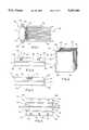
- FIG. 1is an end view of the preferred embodiment of the inventive notebook binder assembly.
- FIG. 2is a perspective view of the notebook binder assembly of FIG. 1.
- FIG. 3is a side view of the bottom member of the unitary spine of FIG. 2.
- FIG. 4is a side view of the top member of the unitary spine of FIG. 3.
- FIG. 5is a plan view of the outer surface of the bottom and top members of the unitary spine of FIG. 2.
- FIG. 6is a plan view of the inner surface of the bottom and top members of the unitary spine of FIG. 5.
- FIG. 7is a side view of the outer edge of the unitary spine of FIGS. 3-6, illustrating its appearance subsequent to folding along the living hinge.
- FIG. 8is a side view of another embodiment of the unitary spine.
- FIG. 9is a side view of the inner edge of the unitary spine of FIGS. 3-6, illustrating its appearance subsequent to folding along the living hinge.
- FIG. 10is a bottom view of the unitary spine with a mounted booklet.
- FIG. 11is a plan view of the surface of the binder of FIGS. 1 and 2.
- FIG. 12is a cross-sectional view of the binder, taken along lines 12--12 of FIG. 11.
- FIG. 13is a plan view of the first and second parallel walls of the channel of the binder of FIG. 11.
- FIG. 14is a side view of another embodiment of the first parallel wall.
- FIG. 15is a side view of the second parallel wall of the embodiment of FIG. 14.
- FIG. 16is a cross-sectional view of the embodiment of FIGS. 14 and 15, illustrating the appearance of the walls in a binder.
- FIG. 17is a partial perspective view of the binder of FIG. 16, illustrating the insertion of the unitary spine and booklet into the binder channels.
- FIG. 18is a partial cross-sectional view of the binder of FIG. 11, illustrating the insertion in an alternate embodiment of the unitary spine and booklet into the binder channel.
- FIG. 19is a partial cross-section of the binder of FIG. 11, illustrating the appearance in an alternate embodiment of the unitary spine and the booklet subsequent to insertion into the binder channel.
- FIG. 20is a partial cross-section of the binder of FIG. 11, illustrating the appearance in an alternate embodiment of the binder subsequent to the insertion of the unitary spines.
- FIG. 21is a partial cross-section of the binder of FIG. 20, illustrating the appearance of the booklets in an open position.
- FIG. 22is a perspective view of the unitary spine and booklet of FIG. 10, illustrating the insertion of the booklet into the spine.
- FIG. 23is a perspective view of the unitary spine and booklet of FIG. 22, illustrating the positioning of the booklet onto the booklet fastening means.
- FIG. 24is a plan view of the unitary spine and booklet of FIG. 23.
- FIG. 25is a plan view of the binder and front and back covers of the assembly of FIG. 2, illustrating the covers in an open position.
- FIG. 26is a partial cross-sectional view of yet another embodiment of two unitary spines and the binder.
- FIG. 27is a partial cross-sectional view of the binder of FIG. 11, illustrating the preferred insertion of the unitary spine and booklet into a binder channel.
- FIG. 28is a partial cross-sectional view of the binder of FIG. 11, illustrating the preferred appearance of the unitary spine and the booklet subsequent to insertion into a binder channel.
- FIG. 29is an exaggerated plan view of the unitary spine and booklet of FIG. 28, illustrating the flexure of the spine during insertion into a binder channel.
- FIG. 30is a partial cross-sectional view of another embodiment of the invention illustrating two unitary spines mounted to the notebook binder.
- the inventionprovides an assembly, denoted by the numeral 30, for releasably and laterally mounting a plurality of booklets 32 into a notebook binder having, in part, a plurality of unitary spines 34 for removably retaining booklets 32 and a binder 36 for releasably mounting unitary spines 34 into the notebook.
- a front cover 38 and a back cover 40are pivotally attached to binder 36 for covering and protecting the booklets.
- the bookletsare bound along one edge.
- unitary spines 34are generally elongated with a bottom member 42 and a top member 44, each of which includes an inner surface 46, an outer surface 48, an inner edge 50, and an outer edge 52.
- Bottom member 42 and top member 44are integrally and pivotally connected to one another along their inner edges by a living hinge 54.
- Bottom member 42 and top member 44are each inwardly stepped (as indicated by numeral 55) towards living hinge 54.
- Both the bottom and top memberpreferably include rounded corners 56 adjacent inner edge 50 to facilitate insertion of the unitary spines into the binder. Additionally, the members may include rounded corners 58 adjacent outer edge 52.
- a plurality of booklet fastening means 60are preferably located on inner surface 46 of bottom member 42 adjacent outer edge 52 for removably fastening the booklets to the unitary spines (see FIGS. 5, 7).
- Booklet fastening means 60are preferably upstanding projections.
- Booklet fastening means 60may alternatively be located on inner surface 46 of both bottom member 42 and top member 44 for removably fastening the members to each other and to the booklets (FIG. 8).
- Such booklet fastening meansinclude a plurality of larger projections 62 on the bottom member that lockingly engages a plurality of corresponding smaller projections 64 on the top member.
- the booklet fastening means in either of the above-described embodimentsextend through a plurality of perforations 66 adjacent an top edge 68 of booklets 32 (see FIG. 22).
- the bottom and top memberseach include at least one first fastening means 70 on outer surface 48 for forcibly engaging binder 36 during the mounting and removal of unitary spines 34 (see FIGS. 3-4, 6, and 9-10).
- top member 44includes a centrally located upstanding tab 71 (FIGS. 4 and 6).
- bottom member 42includes at least one upstanding tab 71 adjacent each of its ends 72 (FIGS. 3 and 6).
- first fastening means 70is a magnetic or metallic strip 73 and/or a strip of Velcro® hook and loop tape 75 (See FIG. 26).
- Binder 36 of assembly 30is elongated and generally rectangular in shape and includes a top surface 73, a bottom surface 75, a first and second side 77, 79, and a top and bottom portion 81, 83, respectively (see FIGS. 1 and 11).
- a plurality of channels 74longitudinally extend over top surface 73 from top portion 81 to bottom portion 83 of binder 36.
- Channels 74are evenly spaced apart and parallel to one another and are individually defined by first and second parallel walls, 76 and 78, respectively, which extend the length of the channels (FIG. 12).
- Walls 76 and 78each include at least one second fastening means go on an inner surface 82 thereof (FIGS. 12-13 and 26).
- second fastening means 80is an integrally formed ridge 81 that longitudinally extends along inner surface 82 (See FIGS. 12-13).
- walls 76 and 78each include at least one integrally formed and boss 84 that projects outwardly from inner surface 82 of the walls (FIGS. 14-17).
- first wall 76includes a boss adjacent each of its ends 84 which corresponds to the location of upstanding tabs 70 on the bottom member.
- second wall 78includes a centrally located boss which also corresponds to the location of the upstanding tab 70 on the top member.
- the bossesmay be positioned at other various locations along the walls as long as they correspond to the location of the upstanding tabs on the top and bottom members (FIG. 17).
- second fastening means 80include a magnetic or metallic strip 85 and/or a strip of Velcro® hook or loop tape 87 (See FIG. 26).
- the location of these fastening meansmust correspond to the location of the first fastening means on the unitary spines and cooperate therewith (magnet to metal or hook to loop). Indeed, while shown along the most lateral edge of the unitary spines and the bottom of the channels, when magnetic/metallic strips or Velcro® hook and loop tapes are used, they may also be located on the outer walls of the unitary spines and the corresponding walls of the channels.
- Both resilient ridge 81 (FIGS. 18-20) and resilient boss 84 (FIG. 17) of the various embodimentsare forcibly engaged by upstanding tabs 70 on top and bottom members, 42 and 44, respectively, during the mounting and removal of the unitary spines in the binder, which is discussed in greater detail below.
- top edge 68 of booklet 32is inserted into and between bottom member 42 and top member 44 of unitary spines 34, as specifically indicated by arrows A in FIG. 22.
- Perforations 66 of booklet 32are aligned with and engaged by booklet fastening means 60 of bottom member 42 of the unitary spines.
- Booklets 32are then removably secured within unitary spines 34 by folding together bottom member 42 and top member 44 along living hinge 50, in the direction indicated by arrows B in FIG. 23.
- folding the members togethercauses booklet fastening means 60 of bottom member 42 to press firmly against inner surface 46 of top member 44 (FIGS. 7, 23).
- folding the members togethercauses the larger projections on the bottom member to lockingly engage the smaller projections on the top member for removably fastening the members to each another and to the booklets (FIG. 8).
- the folded spines and inserted booklets 32are laterally mounted into the binder with respect to the binder channels by individually inserting unitary spines 34 into channels 74, as indicated by arrow C in FIGS. 18 and 27.
- first fastening means 70 on outer surfaces 48 of unitary spines 34forcibly and laterally engage second fastening means 80 on first and second parallel walls, 76 and 78, respectively.
- the fastening means engage one anotherthe unitary spines experience two simultaneous flexures which allow for their lateral insertion (FIGS. 27-29).
- the first flexureoccurs when bottom and top members, 42 and 44, respectively, of unitary spines 34 pivot on living hinge 50 and move inwardly toward one another (FIG. 27), causing unitary spines 34 to close more tightly around booklet 32 (FIG. 28), as indicated by arrows D and E in the figures.
- This first flexurecauses the unitary spines to function as spring clips when inserted into the binder channels.
- the second flexureoccurs when unitary spines 34 become distorted into a "S-like" configuration as pressure is exerted on first fastening means 70, as indicated by arrows F and exaggerated in FIG. 29.
- This second flexureresults in dual flexing: one, the center of the spines are flexed in one direction while, two, the ends of the spines are flexed in an opposite direction. This distortion primarily occurs as a result of the slight rocking may produce a wiggling motion during the lateral insertion of the spines into the binder channels.
- first and second parallel walls, 76 and 78may flex during insertion of the spines, as shown in FIG. 18.
- first fastening means 70laterally engage second fastening means 80
- the parallel wallsare outwardly deflected, as indicated by arrows G in FIG. 18.
- first fastening means 70pass under and are held in place by second fastening means 80, whereupon the parallel walls spring back to their original upright position, as shown in FIGS. 19 and 20.
- second fastening means 80 on the parallel wallscreates pressure on outer surfaces 48 of unitary spines 34 to additionally secure the booklets within the unitary spines, as indicated by arrows H in FIG. 19.
- the first fastening means 70are upstanding tabs 70
- the second fastening meansare ridges 81
- the mounting processif identical to that as described above.
- unitary spines 34are mounted in a manner similar to that described above except that upstanding tabs 71 on outer surfaces 48 of unitary spines 34 forcibly engage bosses 84 by downwardly deflecting and passing under the bosses where they are securely held in place. As shown by arrows I in FIG. 17, the bosses on parallel walls 76 and 78 of channels 74 are aligned with upstanding tabs 71 on the bottom and top members of the unitary spines.
- unitary spines 34are completely flexible within channels 74 to enable full exposure of the surface area of each booklet during viewing. Moreover, the insertion of unitary spines 34 into channels 74 infringes only slightly upon the margin of booklet 32 that is bound and adjacent its upper edge 68. Therefore, the positioning of unitary spines 34 on booklets 32 does not interfere with or obstruct the pages in the booklets.
- unitary spines 34from binder 36 in the previous embodiments involves reversing the above-described mounting process. Specifically, and in the preferred embodiment, as unitary spines 34 are pulled out and away from channels 74, the bottom and top members of the spines spring apart while the spines flex at different points along their lengths. Likewise, in the alternate embodiment, as the unitary spines are pulled out and away from the channels, the first means to upwardly deflect and pass the second fastening means 80.
- FIGS. 1-2 and 25show assembly 30, including front cover 38, back cover 40, and binder 36.
- the front and back coversare pivotally mounted to binder 36 by a pin 86 which extends through cylindrical channels 88 which are integrally formed with the front and back covers and the binder.
- FIG. 25further shows that the inside 90 of the front and back covers includes a pocket 92 for holding supplemental booklets or other materials.
- the outside 94 of the front and back coversinclude a semi-cylindrical depression 96 adjacent the binder 36 (FIG. 2).
- Binder 36, front cover 38, and back cover 40 of assembly 30are made by injection molding.
- Unitary spines 34may be made by injection molding or any other molding process.
- binder 36, front cover 38, and back cover 40 of assembly 30are constructed is preferably polyethylene but may alternatively be any lightweight material.
- unitary spines 34are preferably made from any appropriate resilient material.
- assembly 30has not been described in terms of approximate measurements, as it should be understood that the dimensions of the assembly may vary according to the nature and size of the booklets or other materials that are releasably mounted therein.
- unitary spine 34'may include channels 100 defined by walls 102 and 104 having at least one fastening means on an inner surface thereof in the form, for example, of ridges 106 and 108.
- upstanding members 110 having beads 112are provided in the binder to engage channels 100.
Landscapes
- Sheet Holders (AREA)
Abstract
Description
Claims (21)
Priority Applications (4)
| Application Number | Priority Date | Filing Date | Title |
|---|---|---|---|
| US08/066,490US5433480A (en) | 1993-05-24 | 1993-05-24 | Notebook binder system |
| CA002124060ACA2124060C (en) | 1993-05-24 | 1994-05-20 | Notebook binder system |
| GB9410138AGB2279038B (en) | 1993-05-24 | 1994-05-20 | Notebook binder system |
| JP6110088AJPH07149090A (en) | 1993-05-24 | 1994-05-24 | Note binder |
Applications Claiming Priority (1)
| Application Number | Priority Date | Filing Date | Title |
|---|---|---|---|
| US08/066,490US5433480A (en) | 1993-05-24 | 1993-05-24 | Notebook binder system |
Publications (1)
| Publication Number | Publication Date |
|---|---|
| US5433480Atrue US5433480A (en) | 1995-07-18 |
Family
ID=22069826
Family Applications (1)
| Application Number | Title | Priority Date | Filing Date |
|---|---|---|---|
| US08/066,490Expired - LifetimeUS5433480A (en) | 1993-05-24 | 1993-05-24 | Notebook binder system |
Country Status (4)
| Country | Link |
|---|---|
| US (1) | US5433480A (en) |
| JP (1) | JPH07149090A (en) |
| CA (1) | CA2124060C (en) |
| GB (1) | GB2279038B (en) |
Cited By (23)
| Publication number | Priority date | Publication date | Assignee | Title |
|---|---|---|---|---|
| USD416938S (en)* | 1997-10-08 | 1999-11-23 | International Service Group, Llc | Sample binder |
| US6082770A (en)* | 1998-12-11 | 2000-07-04 | Lin; Jack K. L. | Fastening device for schedule folder covers |
| US6390713B1 (en) | 2000-11-13 | 2002-05-21 | The Mead Corporation | Adapter for a coil bound notebook |
| US6672785B1 (en) | 2000-11-13 | 2004-01-06 | Meadwestvaco Corporation | Insert for a coil bound notebook |
| US20050232690A1 (en)* | 2002-06-06 | 2005-10-20 | Alessandro Ledda | Binder for sheets or cards |
| GB2422134A (en)* | 2005-01-18 | 2006-07-19 | Acco Uk Ltd | Portable modular filing system |
| US20070252377A1 (en)* | 2006-04-28 | 2007-11-01 | Rania Nabil El-Sorroge | Devices for supporting printed matter |
| US20080111367A1 (en)* | 2006-06-06 | 2008-05-15 | David J. McCabe | Removable binding for book pages |
| US20080113321A1 (en)* | 2004-03-02 | 2008-05-15 | Mattel, Inc. | Interactive Electronic Learning System With Tactile Objects |
| US20080308434A1 (en)* | 2004-01-22 | 2008-12-18 | Ludvigsen A/S | Protective Sleeve For A Disc-Shaped Recording Medium, Such As A Compact Disc, A Holder For A Sleeve And An Assembly Of A Holder And A Sleeve |
| US20090080966A1 (en)* | 2007-09-25 | 2009-03-26 | Esselte Corporation | Modular filing system |
| US20090179068A1 (en)* | 2008-01-14 | 2009-07-16 | Chi-Cheng Gong | File folder with individual holding units |
| US20090245923A1 (en)* | 2008-03-26 | 2009-10-01 | Shang-Chiai Kung | Inner-page structure of a document file |
| WO2011041564A3 (en)* | 2009-09-30 | 2011-07-28 | Striding Trees, Llc | Devices and methods for supporting printed matter |
| US20110278832A1 (en)* | 2010-05-14 | 2011-11-17 | Hans Johann Horn | Albums having variable width spines and the components thereof |
| US8083429B2 (en) | 2009-03-25 | 2011-12-27 | Esselte Corporation | Modular locking binder system |
| US8257325B2 (en) | 2007-06-20 | 2012-09-04 | Medical Components, Inc. | Venous access port with molded and/or radiopaque indicia |
| US20120261460A1 (en)* | 2011-04-13 | 2012-10-18 | Smart Fortune International Limited | File folder |
| US20160353849A1 (en)* | 2015-06-08 | 2016-12-08 | This Is Ground | Modularly customizeable personal electronics carrying case with magnetized accessory system |
| US9517329B2 (en) | 2007-07-19 | 2016-12-13 | Medical Components, Inc. | Venous access port assembly with X-ray discernable indicia |
| US9610432B2 (en) | 2007-07-19 | 2017-04-04 | Innovative Medical Devices, Llc | Venous access port assembly with X-ray discernable indicia |
| US20200086671A1 (en)* | 2018-09-17 | 2020-03-19 | Victor L. MARKS | Notebook With Replaceable Paper Sections |
| WO2020257624A1 (en) | 2019-06-19 | 2020-12-24 | Rocket Innovations, Inc. | Modular notebook system |
Families Citing this family (5)
| Publication number | Priority date | Publication date | Assignee | Title |
|---|---|---|---|---|
| US8702128B2 (en) | 2008-03-24 | 2014-04-22 | ACCO Brands Corporation | Notebook cover with extending hole-punched tabs for facilitating attachment to ringed binder |
| US9796206B2 (en) | 2008-03-24 | 2017-10-24 | ACCO Brands Corporation | Bound component with selectively deployable tabs |
| KR101250756B1 (en)* | 2009-09-21 | 2013-04-04 | 강성모 | GooChul(Hooked Filing) System And Tools For Its Management |
| US10596845B2 (en) | 2010-05-28 | 2020-03-24 | ACCO Brands Corporation | Bound edge tabs for notebook |
| GB2494205A (en)* | 2011-09-05 | 2013-03-06 | Ardle Mcdonough | Magnetic device to hold loose sheets of paper |
Citations (15)
| Publication number | Priority date | Publication date | Assignee | Title |
|---|---|---|---|---|
| US642244A (en)* | 1899-04-15 | 1900-01-30 | Cyrus E Morehouse | Temporary binder. |
| GB948166A (en)* | 1960-11-30 | 1964-01-29 | W & J Jarvis Ltd | Improved attachment means for sheets of paper and the like |
| US3353844A (en)* | 1967-03-07 | 1967-11-21 | Henry N Staats | Book binding |
| US3752503A (en)* | 1971-06-10 | 1973-08-14 | W Holes | Means for releasably binding an album cover and album pages together |
| US3768838A (en)* | 1972-10-10 | 1973-10-30 | R Shibata | Binder |
| US3909141A (en)* | 1974-06-11 | 1975-09-30 | Gen Binding Corp | Clamp binding |
| US4113394A (en)* | 1975-10-23 | 1978-09-12 | Minnesota Mining And Manufacturing Company | Removable binding device |
| US4307972A (en)* | 1979-08-06 | 1981-12-29 | Errichiello D | Looseleaf books with plastic posts |
| US4420086A (en)* | 1980-12-16 | 1983-12-13 | Bardes Products, Inc. | Filing hanger |
| US4445710A (en)* | 1982-09-28 | 1984-05-01 | Jowa | Multisheet binder and assembly |
| US4682792A (en)* | 1985-04-11 | 1987-07-28 | Graham Simmons | Binder for articles such as books and cassettes |
| WO1990004523A1 (en)* | 1988-10-22 | 1990-05-03 | Geevax Limited | Filing devices |
| US4934738A (en)* | 1989-03-31 | 1990-06-19 | Ralph Colonna | Combined document binder and cover holder |
| US5018895A (en)* | 1989-10-12 | 1991-05-28 | Meier Jr Joseph A | Film stacker clip |
| US5104147A (en)* | 1990-11-08 | 1992-04-14 | U.S. Sample Company | Binder system for display book and the like |
Family Cites Families (1)
| Publication number | Priority date | Publication date | Assignee | Title |
|---|---|---|---|---|
| JPS6017375B2 (en)* | 1979-06-20 | 1985-05-02 | 三菱電機株式会社 | Manufacturing method of polyamide resin |
- 1993
- 1993-05-24USUS08/066,490patent/US5433480A/ennot_activeExpired - Lifetime
- 1994
- 1994-05-20CACA002124060Apatent/CA2124060C/ennot_activeExpired - Fee Related
- 1994-05-20GBGB9410138Apatent/GB2279038B/ennot_activeExpired - Fee Related
- 1994-05-24JPJP6110088Apatent/JPH07149090A/enactivePending
Patent Citations (15)
| Publication number | Priority date | Publication date | Assignee | Title |
|---|---|---|---|---|
| US642244A (en)* | 1899-04-15 | 1900-01-30 | Cyrus E Morehouse | Temporary binder. |
| GB948166A (en)* | 1960-11-30 | 1964-01-29 | W & J Jarvis Ltd | Improved attachment means for sheets of paper and the like |
| US3353844A (en)* | 1967-03-07 | 1967-11-21 | Henry N Staats | Book binding |
| US3752503A (en)* | 1971-06-10 | 1973-08-14 | W Holes | Means for releasably binding an album cover and album pages together |
| US3768838A (en)* | 1972-10-10 | 1973-10-30 | R Shibata | Binder |
| US3909141A (en)* | 1974-06-11 | 1975-09-30 | Gen Binding Corp | Clamp binding |
| US4113394A (en)* | 1975-10-23 | 1978-09-12 | Minnesota Mining And Manufacturing Company | Removable binding device |
| US4307972A (en)* | 1979-08-06 | 1981-12-29 | Errichiello D | Looseleaf books with plastic posts |
| US4420086A (en)* | 1980-12-16 | 1983-12-13 | Bardes Products, Inc. | Filing hanger |
| US4445710A (en)* | 1982-09-28 | 1984-05-01 | Jowa | Multisheet binder and assembly |
| US4682792A (en)* | 1985-04-11 | 1987-07-28 | Graham Simmons | Binder for articles such as books and cassettes |
| WO1990004523A1 (en)* | 1988-10-22 | 1990-05-03 | Geevax Limited | Filing devices |
| US4934738A (en)* | 1989-03-31 | 1990-06-19 | Ralph Colonna | Combined document binder and cover holder |
| US5018895A (en)* | 1989-10-12 | 1991-05-28 | Meier Jr Joseph A | Film stacker clip |
| US5104147A (en)* | 1990-11-08 | 1992-04-14 | U.S. Sample Company | Binder system for display book and the like |
Cited By (39)
| Publication number | Priority date | Publication date | Assignee | Title |
|---|---|---|---|---|
| USD416938S (en)* | 1997-10-08 | 1999-11-23 | International Service Group, Llc | Sample binder |
| US6082770A (en)* | 1998-12-11 | 2000-07-04 | Lin; Jack K. L. | Fastening device for schedule folder covers |
| US6390713B1 (en) | 2000-11-13 | 2002-05-21 | The Mead Corporation | Adapter for a coil bound notebook |
| US6672785B1 (en) | 2000-11-13 | 2004-01-06 | Meadwestvaco Corporation | Insert for a coil bound notebook |
| US20050232690A1 (en)* | 2002-06-06 | 2005-10-20 | Alessandro Ledda | Binder for sheets or cards |
| US20080308434A1 (en)* | 2004-01-22 | 2008-12-18 | Ludvigsen A/S | Protective Sleeve For A Disc-Shaped Recording Medium, Such As A Compact Disc, A Holder For A Sleeve And An Assembly Of A Holder And A Sleeve |
| US20080113321A1 (en)* | 2004-03-02 | 2008-05-15 | Mattel, Inc. | Interactive Electronic Learning System With Tactile Objects |
| GB2422134A (en)* | 2005-01-18 | 2006-07-19 | Acco Uk Ltd | Portable modular filing system |
| US7744128B2 (en)* | 2006-04-28 | 2010-06-29 | Striding Trees, Llc | Devices and methods for supporting printed matter |
| US20070252377A1 (en)* | 2006-04-28 | 2007-11-01 | Rania Nabil El-Sorroge | Devices for supporting printed matter |
| US20080111367A1 (en)* | 2006-06-06 | 2008-05-15 | David J. McCabe | Removable binding for book pages |
| US11878137B2 (en) | 2006-10-18 | 2024-01-23 | Medical Components, Inc. | Venous access port assembly with X-ray discernable indicia |
| US8257325B2 (en) | 2007-06-20 | 2012-09-04 | Medical Components, Inc. | Venous access port with molded and/or radiopaque indicia |
| US8852160B2 (en) | 2007-06-20 | 2014-10-07 | Medical Components, Inc. | Venous access port with molded and/or radiopaque indicia |
| US11478622B2 (en) | 2007-06-20 | 2022-10-25 | Medical Components, Inc. | Venous access port with molded and/or radiopaque indicia |
| US11938296B2 (en) | 2007-06-20 | 2024-03-26 | Medical Components, Inc. | Venous access port with molded and/or radiopaque indicia |
| US9533133B2 (en) | 2007-06-20 | 2017-01-03 | Medical Components, Inc. | Venous access port with molded and/or radiopaque indicia |
| US11406808B2 (en) | 2007-06-20 | 2022-08-09 | Medical Components, Inc. | Venous access port with molded and/or radiopaque indicia |
| US12274850B2 (en) | 2007-07-19 | 2025-04-15 | Medical Components, Inc. | Venous access port assembly with X-ray discernable indicia |
| US9517329B2 (en) | 2007-07-19 | 2016-12-13 | Medical Components, Inc. | Venous access port assembly with X-ray discernable indicia |
| US9610432B2 (en) | 2007-07-19 | 2017-04-04 | Innovative Medical Devices, Llc | Venous access port assembly with X-ray discernable indicia |
| US10639465B2 (en) | 2007-07-19 | 2020-05-05 | Innovative Medical Devices, Llc | Venous access port assembly with X-ray discernable indicia |
| US10874842B2 (en) | 2007-07-19 | 2020-12-29 | Medical Components, Inc. | Venous access port assembly with X-ray discernable indicia |
| US11547843B2 (en) | 2007-07-19 | 2023-01-10 | Innovative Medical Devices, Llc | Venous access port assembly with x-ray discernable indicia |
| US20090080966A1 (en)* | 2007-09-25 | 2009-03-26 | Esselte Corporation | Modular filing system |
| US7802938B2 (en)* | 2007-09-25 | 2010-09-28 | Esselte Corporation | Resilient rod feature in hanging file folder |
| US20090179068A1 (en)* | 2008-01-14 | 2009-07-16 | Chi-Cheng Gong | File folder with individual holding units |
| US20090245923A1 (en)* | 2008-03-26 | 2009-10-01 | Shang-Chiai Kung | Inner-page structure of a document file |
| US8083429B2 (en) | 2009-03-25 | 2011-12-27 | Esselte Corporation | Modular locking binder system |
| WO2011041564A3 (en)* | 2009-09-30 | 2011-07-28 | Striding Trees, Llc | Devices and methods for supporting printed matter |
| US20110278832A1 (en)* | 2010-05-14 | 2011-11-17 | Hans Johann Horn | Albums having variable width spines and the components thereof |
| US20120261460A1 (en)* | 2011-04-13 | 2012-10-18 | Smart Fortune International Limited | File folder |
| US20160353849A1 (en)* | 2015-06-08 | 2016-12-08 | This Is Ground | Modularly customizeable personal electronics carrying case with magnetized accessory system |
| US20200086671A1 (en)* | 2018-09-17 | 2020-03-19 | Victor L. MARKS | Notebook With Replaceable Paper Sections |
| CN113853307A (en)* | 2019-06-19 | 2021-12-28 | 火箭创新公司 | Modular Notebook System |
| US11148455B2 (en) | 2019-06-19 | 2021-10-19 | Rocket Innovations, Inc. | Modular notebook system |
| US11787219B2 (en) | 2019-06-19 | 2023-10-17 | Rocket Innovations, Inc. | Modular notebook system |
| WO2020257624A1 (en) | 2019-06-19 | 2020-12-24 | Rocket Innovations, Inc. | Modular notebook system |
| CN113853307B (en)* | 2019-06-19 | 2024-11-19 | 火箭创新公司 | Modular Notebook System |
Also Published As
| Publication number | Publication date |
|---|---|
| GB2279038A (en) | 1994-12-21 |
| GB2279038B (en) | 1996-06-05 |
| GB9410138D0 (en) | 1994-07-06 |
| CA2124060C (en) | 1999-09-28 |
| JPH07149090A (en) | 1995-06-13 |
| CA2124060A1 (en) | 1994-11-25 |
Similar Documents
| Publication | Publication Date | Title |
|---|---|---|
| US5433480A (en) | Notebook binder system | |
| US4521035A (en) | Paper sheet holders | |
| EP0480532B1 (en) | Device for storing documents | |
| US5380043A (en) | Hypertext book attachment | |
| US4941804A (en) | Plastic multi-ring paper binding system using one piece cover | |
| US4573821A (en) | Window index system for ring binders | |
| US4681474A (en) | Arrangement for holding and filing documents, papers and the like | |
| EP0688268A4 (en) | One hole folder | |
| US5725251A (en) | Modular binder system | |
| US5048869A (en) | Hypertext book attachment | |
| CA1271205A (en) | Magazine and directory cover and holder assembly | |
| US7052045B2 (en) | Labeling device for bound materials | |
| US6200056B1 (en) | Attachment apparatus for securing an electronic device to a loose-leaf support assembly, assemblies including same, and methods | |
| US3221751A (en) | Record keeping apparatus | |
| US4055008A (en) | Account and file book | |
| US5713604A (en) | Paper binding structure and method of forming same | |
| GB2247433A (en) | Ring file insert | |
| US6923590B2 (en) | Paper binding structure and method of forming same | |
| US5364199A (en) | Sheet fastener hinge device | |
| US5180246A (en) | Binding system | |
| US6971815B1 (en) | Binder ring clamp assembly | |
| JP3034440U (en) | Binder type file paper and binder type system notebook | |
| EP1209003A1 (en) | Binding device | |
| US20040100086A1 (en) | Spine-indexing device | |
| US20140232099A1 (en) | Binding system using two binding pieces |
Legal Events
| Date | Code | Title | Description |
|---|---|---|---|
| STPP | Information on status: patent application and granting procedure in general | Free format text:APPLICATION UNDERGOING PREEXAM PROCESSING | |
| AS | Assignment | Owner name:MORNINGSTAR, INC., ILLINOIS Free format text:ASSIGNMENT OF ASSIGNORS INTEREST;ASSIGNORS:GRESHAM, DAVID M.;DAVISON, JOHN W.;SOTO, ROBERT D.;AND OTHERS;REEL/FRAME:006778/0035;SIGNING DATES FROM 19930709 TO 19930719 | |
| AS | Assignment | Owner name:SIGNET BANK/MARYKLAND, MARYLAND Free format text:SECURITY INTEREST;ASSIGNOR:MORNINGSTAR, INC.;REEL/FRAME:007107/0714 Effective date:19940819 | |
| AS | Assignment | Owner name:MCG FINANCE CORPORATION, VIRGINIA Free format text:ASSIGNMENT OF SECURITY AGREEMENT;ASSIGNOR:FIRST UNION NATIONAL BANK (SUCCESSOR IN INTERST TO SIGNET BANK);REEL/FRAME:009367/0711 Effective date:19980624 | |
| FPAY | Fee payment | Year of fee payment:4 | |
| REFU | Refund | Free format text:REFUND - PAYMENT OF MAINTENANCE FEE, 8TH YR, SMALL ENTITY (ORIGINAL EVENT CODE: R2552); ENTITY STATUS OF PATENT OWNER: SMALL ENTITY | |
| FPAY | Fee payment | Year of fee payment:8 | |
| SULP | Surcharge for late payment | Year of fee payment:7 | |
| FPAY | Fee payment | Year of fee payment:12 |