US5433279A - Portable top drive assembly - Google Patents
Portable top drive assemblyDownload PDFInfo
- Publication number
- US5433279A US5433279AUS08/093,721US9372193AUS5433279AUS 5433279 AUS5433279 AUS 5433279AUS 9372193 AUS9372193 AUS 9372193AUS 5433279 AUS5433279 AUS 5433279A
- Authority
- US
- United States
- Prior art keywords
- track
- derrick
- housing
- top drive
- torque
- Prior art date
- Legal status (The legal status is an assumption and is not a legal conclusion. Google has not performed a legal analysis and makes no representation as to the accuracy of the status listed.)
- Expired - Lifetime
Links
- 238000005553drillingMethods0.000claimsdescription26
- 239000012530fluidSubstances0.000claimsdescription6
- 230000000452restraining effectEffects0.000claimsdescription3
- 239000000725suspensionSubstances0.000claimsdescription3
- 238000009434installationMethods0.000description7
- 230000004048modificationEffects0.000description7
- 238000012986modificationMethods0.000description7
- 238000006243chemical reactionMethods0.000description3
- 238000010586diagramMethods0.000description3
- 230000007246mechanismEffects0.000description3
- 238000012546transferMethods0.000description3
- 230000036961partial effectEffects0.000description2
- 230000000717retained effectEffects0.000description2
- 230000000087stabilizing effectEffects0.000description2
- 238000003466weldingMethods0.000description2
- 230000009471actionEffects0.000description1
- 230000003466anti-cipated effectEffects0.000description1
- 230000000712assemblyEffects0.000description1
- 238000000429assemblyMethods0.000description1
- 230000015556catabolic processEffects0.000description1
- 230000002860competitive effectEffects0.000description1
- 230000008878couplingEffects0.000description1
- 238000010168coupling processMethods0.000description1
- 238000005859coupling reactionMethods0.000description1
- 238000013461designMethods0.000description1
- 238000006073displacement reactionMethods0.000description1
- 238000012423maintenanceMethods0.000description1
- 230000001739rebound effectEffects0.000description1
- 230000002829reductive effectEffects0.000description1
- 238000012360testing methodMethods0.000description1
Images


Classifications
- E—FIXED CONSTRUCTIONS
- E21—EARTH OR ROCK DRILLING; MINING
- E21B—EARTH OR ROCK DRILLING; OBTAINING OIL, GAS, WATER, SOLUBLE OR MELTABLE MATERIALS OR A SLURRY OF MINERALS FROM WELLS
- E21B19/00—Handling rods, casings, tubes or the like outside the borehole, e.g. in the derrick; Apparatus for feeding the rods or cables
- E21B19/16—Connecting or disconnecting pipe couplings or joints
- E—FIXED CONSTRUCTIONS
- E21—EARTH OR ROCK DRILLING; MINING
- E21B—EARTH OR ROCK DRILLING; OBTAINING OIL, GAS, WATER, SOLUBLE OR MELTABLE MATERIALS OR A SLURRY OF MINERALS FROM WELLS
- E21B3/00—Rotary drilling
- E21B3/02—Surface drives for rotary drilling
- E21B3/022—Top drives
Definitions
- This inventionrelates to a top drive assembly for use in rotating the drill string of an oilfield drilling rig.
- top drive unitmounted to a guide track extending upwardly within a rig derrick.
- top drive unitsuse either electric or hydraulic power.
- the unitsare generally large and are designed primarily for offshore rigs, although they have been installed in land rigs.
- the rig derrickhas had to be modified to some degree, usually through welding, to be able to accept the size of the machine, the track on which the top drive unit travels, and to be able to accept the torque imparted to the derrick from the top drive unit through the track.
- the derrickhas had to be extended to accommodate the top drive unit.
- the rig's travelling blocks and/or rotary drilling swivelhave had to be replaced or modified in order to work with the top drive unit.
- Top drive implementationrequires a reactive torque absorbing means. This is provided by a vertical guide track or a tensioned cable secured to the derrick. The tensioned cable puts high vertical loads on the derrick, forcing a deration of the hook load capacity. Guide tracks have generally been secured to the derrick in a manner such that significant reactive torque is transmitted to the derrick structure along its length, which has generally been designed for heavy vertical and only nominal torque loads; this has required structural modifications to compensate.
- top drive drilling systemhas not been available on an economical and temporary basis for the vast majority of land drilling rigs and a substantially lesser number of offshore drilling rigs.
- top drivesrequire substantial modifications to the rig. Generally, modifications to a derrick will require structural re-certification. Modifications are time consuming and expensive, and are not usually undertaken for a temporary installation. With all the top drives described in the prior art, the purchase cost of a top drive for a permanent installation in most rigs is not economically justifiable when compared to conventional rotary drilling equipment used in the same drilling application on a competitive basis.
- top drive unitneeded to be compact in order to fit within the wide range of derrick types
- top drivea top drive unit
- the assemblycomprises a linearly extending, unitary, substantially rigid, segmented torque track.
- the trackis mounted so as to extend vertically in the derrick along the major part of the latter's length.
- the trackis parallel with and laterally offset from the wellbore, to allow the top drive and hoisting means to travel vertically in the derrick.
- the trackis formed of a plurality of sections which are disengagably and rigidly joined end to end by suitable means.
- the sectionscan thus be assembled section by section in the derrick to create the unitary track.
- the trackcan be disassembled when desired into easily transportable sections.
- the trackis rigidly and disengagably secured by connection means, located at its base, with the rig. More particularly, a torque beam and clamps can be used to secure the track rigidly to the lower, robust end of the derrick.
- the connection meansserve to hold the track vertically in the derrick and transmit reactive loads from the track to the rig.
- the trackis otherwise free of rigid connection with the derrick. Therefore it can twist axially or deflect laterally if sufficiently loaded.
- a tubular torque bushingrigidly engages the track.
- This bushingis adapted to slide longitudinally along the track but it cannot rotate thereon.
- the trackis preferably of box section and so is the bushing. The latter is slid over the latter to lock them together and prevent relative rotational movement. This rigid lock up of the bushing and track ensures that reactive loads applied to the bushing are transmitted to the track.
- Linking meansare provided which connect the top drive housing and the bushing.
- the linking meansfunction to rigidly restrain the housing against rotation by tying it to the bushing and track.
- the linking meansis a rigid, elongate torque frame, pivotally connected at its ends with the housing and bushing, so that it can pivot about horizontal axes (but not vertical axes).
- the linking meanscan be said to be “rotationally rigid”.
- the linking meansis angularly disposed between bushing and housing, so that it will accommodate lateral displacement of the latter away from the track, for a purpose to be described.
- the assembly as describedembodies certain essential features that are novel in combination. More particularly:
- the linking assemblyconsisting of torque frame and torque bushing, is adapted to transmit both the torque and side reactive loads or forces generated in the top drive housing, to the track;
- the trackis rigidly tied to the rig only at the base of the track.
- reactive loadsare not transmitted to the upper reaches of the derrick.
- the side loadsare small and they are converted into torque loads in the track.
- the free-to-twist track columntransmits all of these torque loads downwardly to the bottom connection, for transmittal into the rig structure.
- This structural arrangementhas enabled use of a relatively slender and light track, which lends itself to portability.
- a plurality of hydraulic motorsare coupled through gear means to rotate a vertical drive shaft assembly that connects the drill string with the swivel and hoisting means.
- a separate portable hydraulic power unitis used to power the top drive and its components, rather than utilizing the rig's power means.
- the power unitsupplies hydraulic fluid to the top drive motors through a clad bundle of hoses suspended from the derrick.
- the bales and elevator of the top driveare pivotally suspended from a collar carried by the lower end of the drive shaft assembly.
- Linearly extendable meanse.g. cylinders
- the top driveis pivotally connected at their rear ends to the rear portion of the top drive housing and at their front ends to the bales, for rotating the bales and elevator forwardly into a horizontal plane. This enables the top drive to be set down on the rig floor, which assists in disassembly.
- the pivotally connected torque frameis coupled with pivotally mounted cylinders connected between the bushing and the housing. This arrangement enables the top drive to be laterally displaced. In this way, the top drive can make connections in the"mousehole" of the rig.
- the inventionrelates to a portable top drive assembly for use with a drilling rig having a base (comprising the rig sub-structure and the robust lower end of the derrick), said rig further having an upstanding derrick operatively aligned over a wellbore, said derrick supporting hoisting means, a swivel and a drill string extending into the wellbore, said top drive assembly comprising: a top drive unit comprising a housing, a drive assembly supported by the housing, and a tubular drive shaft assembly extending vertically through the housing and being connected with the drive assembly for rotation thereby, said drive shaft assembly having upper and lower ends and being connected at its lower end with the drill string and at its upper end with the swivel for suspension from the derrick by the hoisting means; the top drive unit housing being subjected to reactive side and torque loads when the drive shaft rotates the drill string; and apparatus for transmitting the reactive loads from the housing to the rig comprising a linearly extending, substantially rigid torque track extending vertical
- FIG. 1provides a simplified side view of a conventional land drilling rig having the portable top drive system installed
- FIG. 2is a front view showing the top drive unit (some detail omitted) suspended from a rig hoisting assembly;
- FIG. 3is a side view of the top drive unit shown in FIG. 2;
- FIG. 4is a front sectional view of the top drive unit as sectioned through its drive shaft axis
- FIG. 6is a partial front view of the top drive unit, detailing the pipe handling assembly in an unloaded state
- FIG. 7is a front view of the pipe handling assembly of FIG. 6 in the loaded state
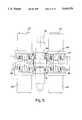
- FIG. 8is an enlarged front view of the load collar and load collar sub of FIGS. 6 and 7;
- FIG. 9is a side view of the top drive system with the pipe handling assembly in a tilted orientation
- FIG. 10is a top view of the top drive system, including the tilted bales and elevators;
- FIG. 11is a side view of a three section torque track assembly in a loosely articulated arrangement
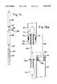
- FIG. 12ais a front sectional view of a disassembled track section joint
- FIG. 12bis a front sectional view of the assembled track section joint of FIG. 12a, showing the joint in a disengaged condition, with a phantom view of an articulated positioning;
- FIG. 13is a front sectional view of the track section joint of FIG. 12b in its final rigidified, engaged form
- FIG. 14is a side view of the top drive unit, torque bushing, torque track upper and lower connection means and torque beam;
- FIG. 15is a top view of the torque track connection means and torque beam according to FIG. 14;
- FIG. 16is a partial side view of the top drive unit, detailing the backup wrench means sectioned through the drill string axis;
- FIG. 17is a top sectional view of the backup wrench, according to FIG. 16, shown in a gripping state of a drill joint;
- FIG. 18is a side view of the top drive system in an extended orientation (pipe handling assembly omitted);
- FIG. 19is a top view of the pivot link frame of FIG. 18;
- FIG. 20is an alternate installation of the torque track on a portable drilling rig
- FIG. 21is a 90° rotated top view of an alternate torque beam used in the installation according to FIG. 20;
- FIG. 22is a free body force diagram of the top drive housing, pivoting link, and torque bushing demonstrating pure side loading forces to the torque bushing assuming an infinitely stiff drill string.
- FIG. 23is a free body force diagram according to FIG. 22 in a substantially torque loaded condition having recognised the flexible nature of the drill string.
- the present inventionprovides an improved portable top drive system for converting conventional kelly and rotary table drilling rigs to top drive.
- a conventional rig 1has a rig sub-structure 2 positioned over a wellbore 3.
- the sub-structure 2has an opening 4 through which a drill string 5 may extend downwards into the wellbore 3.
- the sub-structure 2also usually has a mousehole opening 100 for use in making connections.
- a derrick 6stands above the rig sub-structure 2, operatively aligned relative to the wellbore 3, to support the drill string 5 from hoisting means 7 shown in FIGS. 2 and 3.
- the hoisting means 7comprises a crown block 8, cables 9, travelling block 10 and hook 11 and suspends a swivel 12. Access to the rig is provided through a V-door opening 101 in one side of the derrick 6.
- a top drive unit 13replaces a conventional elevator and is suspended from the swivel 12.
- the swivel 12is in turn suspended from the travelling block 10 and hook 11, which may lift and lower the top drive unit 13 in the derrick 6.
- the drill string 5is suspended from the top drive unit 13. Drilling rotation is imparted to the drill string 5 by the top drive unit 13.
- the top drive unit 13is hydraulically powered and is supplied with actuating fluid via hoses contained within a clad hose bundle 15 extending from a portable power unit 16. Control air and hydraulic lines 17, extending from a control panel 18, and power hydraulic lines 19 are both provided within the hose bundle 15.
- the hose bundle 15is suspended from the derrick 6 to permit free travel of the bundle throughout the range of top drive motion.
- the control panel 18is located on the rig floor 2 and provides a combination of hydraulic, air and electric control of top drive rotational speed (rpm), direction of rotation, pipe handling and other features disclosed later in the description.
- the control panel 18also provides rpm limit and torque limit controls for avoiding situations such as over-speed in case of drill string failure and over-torquing of joints.
- the control panelmay be disconnected from the air, electric and hydraulic lines 17 with quick connectors for shipping.
- the top drive unit 13comprises a structural housing 21, within which is positioned a tubular drive shaft 22, hydraulic drive motors 23, and an oil bath gearbox 24.
- the centrally located drive shaft 22is vertically oriented and is adapted at its upper end 26 to thread into the swivel 12, typically by threaded means directly or by an adapter shaft (not shown).
- the hollow drive shaft 22can transport drilling fluids introduced through a fluid coupling 27 forming part of the swivel 12. Better viewed in FIG. 5, the drive shaft 22 projects through the gearbox 24 and is fitted with an external main gear 28.
- bi-directional rotary hydraulic vane motors 23are mounted to the gearbox 24, parallel to and offset from the drive shaft 22, to rotationally drive pinion gears 29 which mesh with the main gear 28, imparting the required rotational torque.
- Low speed vane motors 23are used to produce high torque at low speed without the need for large, speed reducing gearboxes and their associated bulk weight; this results in a more compact, lighter top drive unit.
- the housing 21employs upper and lower thrust bearings 30, 31 on the drive shaft 22 to transmit the weight of the top drive unit 13, and it's associated, attached components, to the drive shaft 22 and thus to the hoisting means 7.
- the drive shaft 22supports the drill string 5 through intermediary shafts comprising a load collar sub 32 and a kelly saver sub 33. Together they make up a drive shaft assembly.
- a kelly cockmay be optionally included in combination with the saver sub 33.
- the lower end connection 38 of the saver sub 33is adapted to thread into the upper end connection 39 of the drill string 5 in use.
- the saver sub lower end connection 38is regularly connected and disconnected from the upper end connection 39 of the drill string 5 during rig operation.
- the hoisting loads of the drill string 5are transferred through the saver sub 33, the load collar sub 32 and the drive shaft 22 to the hoisting means 7, avoiding loading of the top drive housing 21. This enables use of a compact housing 21.
- locking clamps 40are used.
- the present assemblyis therefore designed to suspend the pipe handling assembly 25 from the housing 21 when its weight is below a predetermined amount and to transfer the load to the drive shaft assembly 205 when the load is increased by picking up drill string.
- the pipe handling assembly 25comprises a load collar 41, elevator bales 42 and an elevator 43.
- the bales 42are pivotally suspended at their upper ends from the load collar 41 and the elevator 43 is pivotally suspended from the lower ends. All three components are conventional in their structure.
- the housing 21has a hollow, cylindrical lower section 21a.
- a pair of parallel bars 46are attached to the sidewall of lower section 21a and extend horizontally on each side of the load collar sub 32.
- a cylindrical spring 45is supported at its lower end by the bars 46 and encircles the load collar sub 32 and extends vertically along part of its length. At its upper end, the spring 45 is received by a ring 45a which supports the load collar 41.
- the load collar 41is annular and forms an internal bore 47. It is mounted around the load collar sub 32.
- the load collar sub 32has an enlarged diameter or upset portion 48 adjacent its lower end.
- the horizontal bars 46are located at the base of this upset portion 48.
- the load collar 41has a recessed load face 49 at its lower end.
- the spring 45If the spring 45 is fully expanded, it supports the load collar 41 in an upraised position, as shown in FIG. 6. In this position, the load face 49 is spaced above the upper end face 206 of the upset portion 48. However, the load collar 41 can slide downwardly along the sub 32 if the resistance of spring 45 is overcome. This downward travel by the load collar 41 is terminated when its load face 49 contacts the end face 206 of the upset portion 48. When the spring 45 is compressed in this manner and the faces 49, 206 are in contact, the load collar 41 is in an engaged position with the drive shaft assembly 205. This is shown in FIG. 7.
- the weight of the empty pipe handling assembly 25is transmitted through the ring 45a, spring 45 and bars 46 to the housing 21.
- the weight of the loaded pipe handling assembly 25is transmitted from the load collar 41 directly to the drive shaft assembly 205.
- the pipe handling assembly 25is shown to be angularly rotatable or tiltable from a normally vertically downward orientation to a near horizontal position by the tilting sub-assembly 44.
- This tilting sub-assembly 44comprises a pair of lift arms 50 pivotally connected at their upper ends with the housing 2 by hole and pin means 52.
- the lift arms 50are also connected at their lower ends with the bales 42 by chains 53.
- Hydraulic cylinders 51are pivotally connected at their inner ends by hole and pin means 55 with the housing 21 and at their outer ends by hole and pin means 56 with the lift arms 50. Extension of the hydraulic cylinders 51 can pivot the bales 42 upwardly and forwardly. This facilitates positioning the elevator 43 as required for pipe handling and enables setting the top drive unit 13 down on the rig floor 2.
- the elevator 43is conventional and has air powered actuators 57 to automate opening and closing functions. For safety reasons, the force developed by the air actuators 57 is insufficient to open the elevators 43 when loaded with a drill pipe.
- the pipe handling assembly 25provides improved pipe handling, being capable of tilting the elevator 43 closer to the derrickman, allowing him to avoid the dangerous reach-out over space to pull back, capture or deliver pipe stands thereto during racking-back and tripping operations.
- a tilt stop means 58is provided to prevent over-rotation of the elevator 43 and accidental contact with the derrick structure 6.
- the tilt stop means 58may be in the form of a limited length chain stop and may be temporarily disabled to allow full rotation when setting the top drive down.
- the portable top drive unit 13may be set aside and the rig 1 may revert to conventional operation in typically less than half an hour. With the tilt stop 58 disabled and the pipe handling assembly 25 fully tilted to nearly horizontal, the top drive unit 13 may be set down on any strong surface, such as the rig floor 2. The swivel 12 can be quickly unscrewed from the top drive 13, and the standard kelly may be reinstalled for re-implementation of the conventional rotary table and kelly operation.
- a torque track 20is mounted in the derrick 6 and extends vertically along the major part of the derrick's length.
- the track 20is of box-section and is substantially rigid. It is spaced rearwardly from the wellbore 3. It is rigidly connected at its lower end to the base of the derrick 6 and is suspended from the top of the derrick by a twistable, flexible cable 79.
- the track 20is therefore rigidly connected to the rig only at its lower end and is free to twist axially and deflect laterally.
- the torque track 20is connected with the housing 21 of the top drive unit 13 by an assembly comprising a torque bushing 59 and a linking means, specifically a torque frame 102.
- the bushing 59is tubular and box-like in section. It fits around and is slidable on the stationary track 20. Because of their box-like configurations, the bushing 59 rigidly engages the track 20 so that it cannot rotate thereon but will transmit reactive loads to it. Stated otherwise, the bushing 59 is rotationally rigid relative to the track 20.
- the bushing 59is internally faced with ultra high molecular weight plastic having a low coefficient of friction, so that it slides easily on the track 20. It has a longitudinal slot 61 on one side to permit it to move past the connection means with the derrick 6.
- the torque frame 102is a rigid, flat, elongate member, angularly disposed and pivotally connected at its ends by horizontal pin and hole means 201, 202 with the housing 21 and bushing 59.
- the frame 102thus can pivot about horizontal axes, relative to the housing 21 and bushing 59, but it is restrained by the bushing from rotating relative to the track 20. Stated otherwise, the torque frame is rotationally rigid relative to the housing 21 and bushing 59.
- the top drive unit 13generates reactive side and torque loads when drilling. These loads are transmitted from the housing 21, through the frame 102 and bushing 59, to the track 20.
- the track 20transmits the loads to the rig 1 through its rigid connection therewith.
- the track 20, bushing 59 and frame 102further cooperate to guide the top drive unit 13 as it travels in the derrick 6.
- the elongate form, angular positioning and pivoting capability of the frame 102enables the top drive unit 13 to be displaced forwardly, so that it may be positioned over the mousehole or laid down on the rig floor.
- the torque track 20is assembled from a plurality of sections of rectangular cross-section tubing, typically sized to standard oilfield drill pipe shipping lengths. In the particular embodiment shown in FIG. 11, three sections are depicted: a bottom section 63; a middle section 64; and a top section 65.
- the bottom section 63is fitted with a plurality of frequently spaced mounting bolt holes 104 along its length to permit adapting to the particular derrick 6 being fitted with the track 20.
- the middle and top sections 64, 65may be identical and have articulated assembly joints 66 mounted at each end, as seen in assembly FIGS. 12a, 12b and 13.
- the lower joint end of the top section 65cooperates with the matching upper joint end of the middle section 64 to permit angular articulation during installation, yet when the sections 64, 65 are placed in collinear alignment they may be fitted together to form the linearly contiguous, unitary structural torque track 20.
- the upper end of a cable 69is fitted loosely through a first closing plate 70 and is retained from slipping through with a button stop 71 at the cable end.
- the lower end of the cable 69is similarly loosely fitted through a J-lock fitting 72a and is retained with a button stop 73.
- the 1/8 turn J-lock 72aadapts to disengagably connect the cable to a matching J-lock receiving fitting 72b on a second closing plate 74.
- the cableis of a suitable length that the track sections may articulate freely with a flexing of the cable, yet is short enough to retract within the track when the sections are drawn together.
- a protuberance 75a extending from the first closing plate 70is adapted to fit into a matching opening 75b in the second closing plate 74. The protuberance engages the opening 75b until a bolting flange 75c contacts the second closing plate 74 thereby aligning and stabilizing the sections together.
- Locking means 76such as bolts are employed to rigidly join the track sections 64, 65.
- the bottom section 63is similarly joined to the middle section 64 to complete the torque track 20 assembly.
- the torque track 20is secured to the derrick 6 with an upper and a lower connection means 77, 78.
- the upper connection means 77comprises a cable 79 attaching the upper joint end of the top track section 65 to a suitable cross-brace 80 at the crown of the derrick. 6 with a clamping means 81.
- the upper connection means 77includes a vertical adjusting means 77b, such as a turnbuckle, to provide limited vertical adjustment.
- the torque track 20is suspended by this upper connection means 77 which is capable of stabilizing horizontal movement of the torque track and yet freely rotates when subjected to torque loading.
- the lower connection means 78comprises a torque arm 82a connected to and projecting laterally from the torque track 20.
- the torque arm 82amay be connected using any of a plurality of bolting holes (not shown) formed along the track, to adapt to variable geometry of different derricks 6.
- a torque beam 82bis connected to the torque arm to connect to suitable bracing 83 on the derrick 6 near its robust base where reactive drilling torques may safely be absorbed.
- the torque track 20is designed with sufficient torsional rigidity to transmit the full reactive drilling torque to the rigid lower connection means 78 and into the substructure of the drilling rig 1.
- the torque beam 82bis rigidly attached to the bracing 83 on the derrick 6 with a clamping means 84a which permits connections to be made without need for welding or other structural modifications to be made to the derrick 6.
- the torque armis similarly rigidly attached to the torque beam with a clamping means 84b.
- the clamping means 84a, 84bpermit adjustments to re-align the torque track 20 to the wellbore as required.
- the mechanism that permits the torque track to absorb the reactive loads as substantially torque and to prevent side loading of the upper structure of the derrickis not immediately apparent.
- FIG. 22a free body force diagram of the top drive housing 21, pivoting frame 102, and torque bushing 59 is shown.
- the top drive housing 21is depicted as imparting a CW torque T1 to the drill string 5.
- the drill stringresists the rotation and results in a CCW couple C1 into the frame.
- the frameacts as a moment arm which attempts to rotate around the drill string.
- the moment armwill impose purely side loading S2 into the torque bushing 59 and in turn into the torque track 20.
- An equal and opposite balancing load S1then exists in the moment arm.
- a reactive side load R1must exist on the drill string.
- a reactive side load R2must exist at the track. Should the assumption of the stiff drill string be true, high side loading of the torque track would result. High side loads could deflect the track significantly and impose loading to the top of the derrick which is contrary to the objective.
- the drill stringis found to be, not infinitely stiff, but is actually weak in side loading. If R1 is then essentially zero, the moment arm rotates essentially freely and deflects an amount d1, typically a couple of inches. The track is strong in side loading and deflects only a very small amount d2 to balance the small load R1.
- the trackmust rotate with the moment arm or frame, being rigidly fixed thereto.
- the trackhas significant torsional rigidity and resists this rotation. This resistance manifests as a couple C2 and permits a small twist or rotation of the track.
- the reactive side load R2 on the trackdiminishes as the drill string deflects, the load being absorbed in the couple C2.
- the side loading S1has thus been substantially converted to a reactive torque loading C2 into the track.
- the drill string 5is weak and permitting the conversion of side loads to torque loading.
- the drill stringis normally long in length, has a relatively small moment of inertia and it extends down through a large rig-floor opening into the wellbore which offers little support.
- the drill string 5is connected at its upper end to the top drive unit 13 which is connected to the travelling block 10.
- the travelling blockis hung from the crown with cables 9 which are not normally capable of sustaining side loads.
- a steadying meanssuch as turnbuckles 105, connected between the derrick and torque track at vertically spaced points. Bars 106 having a plurality of connecting sites are attached to the torque track 20. Connection of the turnbuckle 105 to each bar 106 is loose enough to permit reactive load movement but is sufficiently rigid to prevent contact of the torque bushing 59 with the derrick 6. Stated otherwise, the connection prevents the track from moving toward or away from the back of the derrick but the connection is loose enough to allow the track to move sideways and most importantly is loose enough that the connection cannot transmit any torque.
- a backup wrench assembly 85comprising opposing rotation drill string tongs 86 having standard oilfield tong jaw dies 87. Individual hydraulic actuating means 88 are provided to cause the tong jaws to hold the drill pipe 5 stationary while the drive shaft 22 is appropriately rotated to connect or disconnect the saver sub joint 38, 39 thereto.
- the wrench assembly 85makes it possible to make or break the tool joint at any position in the derrick.
- the wrench assembly 85is secured to the lower portion of the top drive housing 21 with a spring mount means 89. When disengaging a drill pipe 5 from the saver sub 33, the wrench assembly is positioned to engage the top of the pipe. As the saver sub is screwed out of the drill pipe 5, the springs 89 deflect, permitting both the pipe 5 and the wrench assembly 85 to be moved down by the pitch action of the threads.
- a hydraulic cylinder 95is pivotally connected at its ends by horizontal pin and hole means 203, 204 with the torque bushing 59 and top drive housing 21. Extension of the cylinder 90 will shift the top drive unit 13 forwardly; the pivoting frame 102 accommodates this movement. The top drive unit 13 can thus be biased to an alternate position, such as over the mousehole 100.
- the torque track 20may not be feasible to locate the torque track 20 at the back of the derrick 6. This can occur in the case of a portable rig 103 having a leaning derrick 6, where an obstacle free path is not available from the rig floor 2 to the crown of the derrick (FIGS. 20 and 21). In this case, the torque track 20 may be installed at right angles from the wellbore 3 and mousehole 100 alignment.
- the torque track 20is suspended from the crown brace 80 with the upper connection means 77 as previously described, but the lower connection means 78 is provided by a telescoping torque beam assembly 96, whereby the first end of the beam 97 is secured to the robust base of the derrick 6 with the clamping means 84 and the second end 98 is moveable with respect to the first and is pivotally connected to the torque track 20.
- An extending and retracting means 99is provided to extend the second end 98 with respect to the first end, resulting in a pivoting of the entire track 20, from the crown bracing 80, thereby extending the top drive unit 13 from a position over the wellbore 3 to an alternate position such as over the mousehole 100.
- the extend featurepermits the mousehole, offset from the wellbore, to be drilled by the top drive. It is possible to make up drill pipe connections at the mousehole with the joint connection at the rig floor, at eye level. Stands of drill pipe can be made up over the mousehole, improving drilling efficiency.
- the top drivemay drill to the floor and, using a combination of extend and the tilt elevator, one can simultaneously pick up a new length of pipe from the V-door.
- the extend featuremay also be used to further assist the derrickman in handling drill collars, as the bales and elevator can then bring the particularly heavy collars closer.
Landscapes
- Engineering & Computer Science (AREA)
- Life Sciences & Earth Sciences (AREA)
- Geology (AREA)
- Mining & Mineral Resources (AREA)
- Mechanical Engineering (AREA)
- Physics & Mathematics (AREA)
- Environmental & Geological Engineering (AREA)
- Fluid Mechanics (AREA)
- General Life Sciences & Earth Sciences (AREA)
- Geochemistry & Mineralogy (AREA)
- Earth Drilling (AREA)
Abstract
Description
Claims (9)
Priority Applications (2)
| Application Number | Priority Date | Filing Date | Title |
|---|---|---|---|
| US08/093,721US5433279A (en) | 1993-07-20 | 1993-07-20 | Portable top drive assembly |
| CA002118608ACA2118608C (en) | 1993-07-20 | 1994-03-09 | Portable top drive assembly |
Applications Claiming Priority (1)
| Application Number | Priority Date | Filing Date | Title |
|---|---|---|---|
| US08/093,721US5433279A (en) | 1993-07-20 | 1993-07-20 | Portable top drive assembly |
Publications (1)
| Publication Number | Publication Date |
|---|---|
| US5433279Atrue US5433279A (en) | 1995-07-18 |
Family
ID=22240373
Family Applications (1)
| Application Number | Title | Priority Date | Filing Date |
|---|---|---|---|
| US08/093,721Expired - LifetimeUS5433279A (en) | 1993-07-20 | 1993-07-20 | Portable top drive assembly |
Country Status (2)
| Country | Link |
|---|---|
| US (1) | US5433279A (en) |
| CA (1) | CA2118608C (en) |
Cited By (130)
| Publication number | Priority date | Publication date | Assignee | Title |
|---|---|---|---|---|
| WO1996008631A1 (en)* | 1994-09-13 | 1996-03-21 | Richardson Allan S | Portable top drive |
| US5921329A (en)* | 1996-10-03 | 1999-07-13 | Sundowner Offshore Services, Inc. | Installation and removal of top drive units |
| US20030141111A1 (en)* | 2000-08-01 | 2003-07-31 | Giancarlo Pia | Drilling method |
| US6622796B1 (en)* | 1998-12-24 | 2003-09-23 | Weatherford/Lamb, Inc. | Apparatus and method for facilitating the connection of tubulars using a top drive |
| US6688398B2 (en) | 1998-08-24 | 2004-02-10 | Weatherford/Lamb, Inc. | Method and apparatus for connecting tubulars using a top drive |
| US6705405B1 (en) | 1998-08-24 | 2004-03-16 | Weatherford/Lamb, Inc. | Apparatus and method for connecting tubulars using a top drive |
| US6725938B1 (en) | 1998-12-24 | 2004-04-27 | Weatherford/Lamb, Inc. | Apparatus and method for facilitating the connection of tubulars using a top drive |
| US6742596B2 (en) | 2001-05-17 | 2004-06-01 | Weatherford/Lamb, Inc. | Apparatus and methods for tubular makeup interlock |
| US20040129417A1 (en)* | 2002-12-10 | 2004-07-08 | Nelson Allan R | Drilling rig with torque carrier |
| US20050022985A1 (en)* | 2003-07-31 | 2005-02-03 | Nelson Allan R. | Service rig with torque carrier |
| US20050051343A1 (en)* | 1998-07-22 | 2005-03-10 | Weatherford/Lamb, Inc. | Apparatus for facilitating the connection of tubulars using a top drive |
| US20050269072A1 (en)* | 2004-06-07 | 2005-12-08 | Folk Robert A | Wellbore top drive power systems & methods of use |
| US6976298B1 (en)* | 1998-08-24 | 2005-12-20 | Weatherford/Lamb, Inc. | Methods and apparatus for connecting tubulars using a top drive |
| US6994176B2 (en) | 2002-07-29 | 2006-02-07 | Weatherford/Lamb, Inc. | Adjustable rotating guides for spider or elevator |
| US7004264B2 (en) | 2002-03-16 | 2006-02-28 | Weatherford/Lamb, Inc. | Bore lining and drilling |
| US7013997B2 (en) | 1994-10-14 | 2006-03-21 | Weatherford/Lamb, Inc. | Methods and apparatus for cementing drill strings in place for one pass drilling and completion of oil and gas wells |
| US7036610B1 (en) | 1994-10-14 | 2006-05-02 | Weatherford / Lamb, Inc. | Apparatus and method for completing oil and gas wells |
| US7040420B2 (en) | 1994-10-14 | 2006-05-09 | Weatherford/Lamb, Inc. | Methods and apparatus for cementing drill strings in place for one pass drilling and completion of oil and gas wells |
| US20060113084A1 (en)* | 2004-11-30 | 2006-06-01 | Springett Frank B | Pipe gripper and top drive systems |
| USD523210S1 (en) | 2004-06-07 | 2006-06-13 | Varco I/P, Inc. | Block becket for use in a wellbore derrick |
| USD523451S1 (en) | 2004-06-07 | 2006-06-20 | Varco I/P, Inc. | Support link for wellbore apparatus |
| USD524334S1 (en) | 2004-06-07 | 2006-07-04 | Varco I/P, Inc. | Swivel body for a well top drive system |
| USD524833S1 (en) | 2004-06-07 | 2006-07-11 | Varco I/P, Inc. | Access platform for a well top drive system |
| US7083005B2 (en) | 2002-12-13 | 2006-08-01 | Weatherford/Lamb, Inc. | Apparatus and method of drilling with casing |
| US7090023B2 (en) | 2002-10-11 | 2006-08-15 | Weatherford/Lamb, Inc. | Apparatus and methods for drilling with casing |
| US7096982B2 (en) | 2003-02-27 | 2006-08-29 | Weatherford/Lamb, Inc. | Drill shoe |
| US7100713B2 (en) | 2000-04-28 | 2006-09-05 | Weatherford/Lamb, Inc. | Expandable apparatus for drift and reaming borehole |
| US7100710B2 (en) | 1994-10-14 | 2006-09-05 | Weatherford/Lamb, Inc. | Methods and apparatus for cementing drill strings in place for one pass drilling and completion of oil and gas wells |
| US7108084B2 (en) | 1994-10-14 | 2006-09-19 | Weatherford/Lamb, Inc. | Methods and apparatus for cementing drill strings in place for one pass drilling and completion of oil and gas wells |
| US7117957B2 (en) | 1998-12-22 | 2006-10-10 | Weatherford/Lamb, Inc. | Methods for drilling and lining a wellbore |
| US7128154B2 (en) | 2003-01-30 | 2006-10-31 | Weatherford/Lamb, Inc. | Single-direction cementing plug |
| US7131505B2 (en) | 2002-12-30 | 2006-11-07 | Weatherford/Lamb, Inc. | Drilling with concentric strings of casing |
| US7140445B2 (en) | 1997-09-02 | 2006-11-28 | Weatherford/Lamb, Inc. | Method and apparatus for drilling with casing |
| US7147068B2 (en) | 1994-10-14 | 2006-12-12 | Weatherford / Lamb, Inc. | Methods and apparatus for cementing drill strings in place for one pass drilling and completion of oil and gas wells |
| US7165634B2 (en) | 1994-10-14 | 2007-01-23 | Weatherford/Lamb, Inc. | Method and apparatus for cementing drill strings in place for one pass drilling and completion of oil and gas wells |
| US7188687B2 (en) | 1998-12-22 | 2007-03-13 | Weatherford/Lamb, Inc. | Downhole filter |
| US7191840B2 (en) | 2003-03-05 | 2007-03-20 | Weatherford/Lamb, Inc. | Casing running and drilling system |
| US7216727B2 (en) | 1999-12-22 | 2007-05-15 | Weatherford/Lamb, Inc. | Drilling bit for drilling while running casing |
| US7228901B2 (en) | 1994-10-14 | 2007-06-12 | Weatherford/Lamb, Inc. | Method and apparatus for cementing drill strings in place for one pass drilling and completion of oil and gas wells |
| US20070131416A1 (en)* | 2003-03-05 | 2007-06-14 | Odell Albert C Ii | Apparatus for gripping a tubular on a drilling rig |
| JP2007521424A (en)* | 2003-10-09 | 2007-08-02 | バーコ アイ/ピー,インコーポレイティド | Tubular makeup control system |
| US7264067B2 (en) | 2003-10-03 | 2007-09-04 | Weatherford/Lamb, Inc. | Method of drilling and completing multiple wellbores inside a single caisson |
| US20070209805A1 (en)* | 2006-02-08 | 2007-09-13 | Tesco Corporation | Method and assembly for casing handling using a kelly rig |
| USD551682S1 (en) | 2006-09-08 | 2007-09-25 | Varco I/P, Inc. | Guard for well operations apparatus |
| USD552628S1 (en) | 2006-09-08 | 2007-10-09 | Varco I/P, Inc. | Guard for well operations apparatus |
| EP1676015A4 (en)* | 2003-10-09 | 2007-10-10 | Varco Int | Make-up control system for tubulars |
| US7284617B2 (en) | 2004-05-20 | 2007-10-23 | Weatherford/Lamb, Inc. | Casing running head |
| US20070251705A1 (en)* | 2006-04-28 | 2007-11-01 | Wells Lawrence E | Multi-seal for top drive shaft |
| US20070251699A1 (en)* | 2006-04-28 | 2007-11-01 | Wells Lawrence E | Top drive systems |
| US7303022B2 (en) | 2002-10-11 | 2007-12-04 | Weatherford/Lamb, Inc. | Wired casing |
| US7311148B2 (en) | 1999-02-25 | 2007-12-25 | Weatherford/Lamb, Inc. | Methods and apparatus for wellbore construction and completion |
| US7320374B2 (en) | 2004-06-07 | 2008-01-22 | Varco I/P, Inc. | Wellbore top drive systems |
| US7325610B2 (en) | 2000-04-17 | 2008-02-05 | Weatherford/Lamb, Inc. | Methods and apparatus for handling and drilling with tubulars or casing |
| WO2007070805A3 (en)* | 2005-12-12 | 2008-02-07 | Weatherford Lamb | Apparatus for gripping a tubular on a drilling rig |
| US7334650B2 (en) | 2000-04-13 | 2008-02-26 | Weatherford/Lamb, Inc. | Apparatus and methods for drilling a wellbore using casing |
| US20080060818A1 (en)* | 2006-09-07 | 2008-03-13 | Joshua Kyle Bourgeois | Light-weight single joint manipulator arm |
| US7360594B2 (en) | 2003-03-05 | 2008-04-22 | Weatherford/Lamb, Inc. | Drilling with casing latch |
| US20080093127A1 (en)* | 2004-11-08 | 2008-04-24 | Tesco Corporation | Wellbore Tubular Handling Torque Multiplier |
| US7370707B2 (en) | 2003-04-04 | 2008-05-13 | Weatherford/Lamb, Inc. | Method and apparatus for handling wellbore tubulars |
| US20080135228A1 (en)* | 2006-12-12 | 2008-06-12 | Wells Lawrence E | Tubular grippers and top drive systems |
| US20080136109A1 (en)* | 2006-12-06 | 2008-06-12 | Neil Edward West | Top drive oil flow path seals |
| USD572119S1 (en) | 2007-06-27 | 2008-07-01 | Varco I/P, Inc. | Support bail |
| US7413020B2 (en) | 2003-03-05 | 2008-08-19 | Weatherford/Lamb, Inc. | Full bore lined wellbores |
| WO2008102175A1 (en) | 2007-02-22 | 2008-08-28 | National Oilwell Varco, L.P. | Top drive apparatus |
| US20080210437A1 (en)* | 2007-03-02 | 2008-09-04 | Lawrence Edward Wells | Top drive with shaft seal isolation |
| US20080302525A1 (en)* | 2003-11-10 | 2008-12-11 | Beierbach K Evert | Pipe handling device, method and system |
| US20090000780A1 (en)* | 2007-06-27 | 2009-01-01 | Wells Lawrence E | Top drive systems with reverse bend bails |
| US7503397B2 (en) | 2004-07-30 | 2009-03-17 | Weatherford/Lamb, Inc. | Apparatus and methods of setting and retrieving casing with drilling latch and bottom hole assembly |
| US7509722B2 (en) | 1997-09-02 | 2009-03-31 | Weatherford/Lamb, Inc. | Positioning and spinning device |
| US20090151934A1 (en)* | 2007-12-12 | 2009-06-18 | Karsten Heidecke | Top drive system |
| US20090159271A1 (en)* | 2007-12-21 | 2009-06-25 | Bastiaan De Jong | Top drive systems for wellbore & drilling operations |
| US20090183918A1 (en)* | 2008-01-17 | 2009-07-23 | Randy Steven Stoik | Methods and systems for drilling auxiliary holes |
| US20090321086A1 (en)* | 2008-06-30 | 2009-12-31 | Tesco Corporation (Us) | Power Screw Actuator for Pipe Gripper |
| US7650944B1 (en) | 2003-07-11 | 2010-01-26 | Weatherford/Lamb, Inc. | Vessel for well intervention |
| US7669662B2 (en) | 1998-08-24 | 2010-03-02 | Weatherford/Lamb, Inc. | Casing feeder |
| US7694744B2 (en) | 2005-01-12 | 2010-04-13 | Weatherford/Lamb, Inc. | One-position fill-up and circulating tool and method |
| US7712523B2 (en) | 2000-04-17 | 2010-05-11 | Weatherford/Lamb, Inc. | Top drive casing system |
| US7757759B2 (en) | 2006-04-27 | 2010-07-20 | Weatherford/Lamb, Inc. | Torque sub for use with top drive |
| US20100263934A1 (en)* | 2009-04-15 | 2010-10-21 | Shawn James Nielsen | Method of protecting a top drive drilling assembly and a top drive drilling assembly modified in accordance with this method |
| US20100283241A1 (en)* | 2007-03-28 | 2010-11-11 | Varco I/P, Inc. | Clamp Apparatus for Threadedly Connected Tubulars |
| US20100288560A1 (en)* | 2008-09-26 | 2010-11-18 | Longyear Tm, Inc. | Modular rotary drill head |
| US20100300704A1 (en)* | 2009-05-29 | 2010-12-02 | Tesco Corporation | Casing Stabbing Guide |
| US7845418B2 (en) | 2005-01-18 | 2010-12-07 | Weatherford/Lamb, Inc. | Top drive torque booster |
| US7882902B2 (en) | 2006-11-17 | 2011-02-08 | Weatherford/Lamb, Inc. | Top drive interlock |
| US20110168397A1 (en)* | 2008-09-22 | 2011-07-14 | Churchill Drilling Tools Limited | Apparatus for use in top filling of tubulars and associated methods |
| US20110203820A1 (en)* | 2010-02-23 | 2011-08-25 | Adrian Marica | Track guiding system |
| US20110214919A1 (en)* | 2010-03-05 | 2011-09-08 | Mcclung Iii Guy L | Dual top drive systems and methods |
| USRE42877E1 (en) | 2003-02-07 | 2011-11-01 | Weatherford/Lamb, Inc. | Methods and apparatus for wellbore construction and completion |
| US8181721B1 (en)* | 2010-08-23 | 2012-05-22 | Keast Larry G | Torque track and slide assembly |
| RU2483186C2 (en)* | 2008-02-29 | 2013-05-27 | НЭШНЛ ОЙЛВЕЛЛ ВАРКО, Эл.Пи. | Method for facilitating drilling plant installation |
| US8651175B2 (en) | 2011-01-14 | 2014-02-18 | Tesco Corporation | Top drive output torque measurement method |
| US8739888B2 (en) | 2011-04-28 | 2014-06-03 | Tesco Corporation | Mechanically actuated casing drive system tool |
| WO2014004894A3 (en)* | 2012-06-29 | 2014-11-20 | Tesco Corporation | Top drive counter moment system |
| US9010410B2 (en) | 2011-11-08 | 2015-04-21 | Max Jerald Story | Top drive systems and methods |
| USRE45898E1 (en) | 2002-12-19 | 2016-02-23 | Schlumberger Technology Corporation | Method and apparatus for directional drilling |
| CN105822236A (en)* | 2016-05-10 | 2016-08-03 | 甘肃蓝科石化高新装备股份有限公司 | Centering adjusting device for top-drive guide rail |
| CN106351569A (en)* | 2015-11-05 | 2017-01-25 | 衡阳中地装备探矿工程机械有限公司 | Top drive type core drill power head guiding device |
| EP3369887A1 (en)* | 2017-03-02 | 2018-09-05 | Weatherford Technology Holdings, LLC | Dual torque transfer for top drive system |
| US20180305982A1 (en)* | 2017-04-20 | 2018-10-25 | Cameron International Corporation | Top Drive System and Method |
| US10167671B2 (en) | 2016-01-22 | 2019-01-01 | Weatherford Technology Holdings, Llc | Power supply for a top drive |
| US10247246B2 (en) | 2017-03-13 | 2019-04-02 | Weatherford Technology Holdings, Llc | Tool coupler with threaded connection for top drive |
| US10309166B2 (en) | 2015-09-08 | 2019-06-04 | Weatherford Technology Holdings, Llc | Genset for top drive unit |
| US10323484B2 (en) | 2015-09-04 | 2019-06-18 | Weatherford Technology Holdings, Llc | Combined multi-coupler for a top drive and a method for using the same for constructing a wellbore |
| US10355403B2 (en) | 2017-07-21 | 2019-07-16 | Weatherford Technology Holdings, Llc | Tool coupler for use with a top drive |
| US10364604B2 (en)* | 2015-12-18 | 2019-07-30 | Soilmec S.P.A | Device and method for the movement and mutual assembly of segments of an excavation battery, for example auger or rod segments |
| US10428602B2 (en) | 2015-08-20 | 2019-10-01 | Weatherford Technology Holdings, Llc | Top drive torque measurement device |
| US10443326B2 (en) | 2017-03-09 | 2019-10-15 | Weatherford Technology Holdings, Llc | Combined multi-coupler |
| US10465457B2 (en) | 2015-08-11 | 2019-11-05 | Weatherford Technology Holdings, Llc | Tool detection and alignment for tool installation |
| US10480247B2 (en) | 2017-03-02 | 2019-11-19 | Weatherford Technology Holdings, Llc | Combined multi-coupler with rotating fixations for top drive |
| US10527104B2 (en) | 2017-07-21 | 2020-01-07 | Weatherford Technology Holdings, Llc | Combined multi-coupler for top drive |
| US10526844B2 (en) | 2016-03-02 | 2020-01-07 | Mhwirth As | Top drive for a drilling rig |
| US10526852B2 (en) | 2017-06-19 | 2020-01-07 | Weatherford Technology Holdings, Llc | Combined multi-coupler with locking clamp connection for top drive |
| US10544631B2 (en) | 2017-06-19 | 2020-01-28 | Weatherford Technology Holdings, Llc | Combined multi-coupler for top drive |
| US10590744B2 (en) | 2015-09-10 | 2020-03-17 | Weatherford Technology Holdings, Llc | Modular connection system for top drive |
| US10626683B2 (en) | 2015-08-11 | 2020-04-21 | Weatherford Technology Holdings, Llc | Tool identification |
| US10704364B2 (en) | 2017-02-27 | 2020-07-07 | Weatherford Technology Holdings, Llc | Coupler with threaded connection for pipe handler |
| US10711574B2 (en) | 2017-05-26 | 2020-07-14 | Weatherford Technology Holdings, Llc | Interchangeable swivel combined multicoupler |
| US10745978B2 (en) | 2017-08-07 | 2020-08-18 | Weatherford Technology Holdings, Llc | Downhole tool coupling system |
| US10760417B2 (en) | 2018-01-30 | 2020-09-01 | Schlumberger Technology Corporation | System and method for surface management of drill-string rotation for whirl reduction |
| US10782197B2 (en) | 2017-12-19 | 2020-09-22 | Schlumberger Technology Corporation | Method for measuring surface torque oscillation performance index |
| US10895111B1 (en)* | 2019-07-10 | 2021-01-19 | Gordon Bros. Supply, Inc. | Guide for top drive unit |
| US10927658B2 (en) | 2013-03-20 | 2021-02-23 | Schlumberger Technology Corporation | Drilling system control for reducing stick-slip by calculating and reducing energy of upgoing rotational waves in a drillstring |
| US10954753B2 (en) | 2017-02-28 | 2021-03-23 | Weatherford Technology Holdings, Llc | Tool coupler with rotating coupling method for top drive |
| US11047175B2 (en) | 2017-09-29 | 2021-06-29 | Weatherford Technology Holdings, Llc | Combined multi-coupler with rotating locking method for top drive |
| US11060361B2 (en)* | 2016-04-29 | 2021-07-13 | Schlumberger Technology Corporation | Retractable top drive with torque tube |
| US11131151B2 (en) | 2017-03-02 | 2021-09-28 | Weatherford Technology Holdings, Llc | Tool coupler with sliding coupling members for top drive |
| US11162309B2 (en) | 2016-01-25 | 2021-11-02 | Weatherford Technology Holdings, Llc | Compensated top drive unit and elevator links |
| US11441412B2 (en) | 2017-10-11 | 2022-09-13 | Weatherford Technology Holdings, Llc | Tool coupler with data and signal transfer methods for top drive |
| US20230145409A1 (en)* | 2021-11-10 | 2023-05-11 | Larry G. Keast | Telescoping torque reaction track device |
| US20240133253A1 (en)* | 2022-10-25 | 2024-04-25 | Treeline Well Services Lp | Portable Downforce System and Method |
Families Citing this family (2)
| Publication number | Priority date | Publication date | Assignee | Title |
|---|---|---|---|---|
| CN101492996B (en)* | 2008-01-25 | 2011-05-25 | 中国石油天然气集团公司 | Method for controlling rotate speed torquemoment of top driving device of oil rig |
| CN108194031B (en)* | 2018-02-26 | 2024-05-24 | 四川宏华石油设备有限公司 | Top drive guide rail |
- 1993
- 1993-07-20USUS08/093,721patent/US5433279A/ennot_activeExpired - Lifetime
- 1994
- 1994-03-09CACA002118608Apatent/CA2118608C/ennot_activeExpired - Lifetime
Cited By (224)
| Publication number | Priority date | Publication date | Assignee | Title |
|---|---|---|---|---|
| US6024181A (en)* | 1994-09-13 | 2000-02-15 | Nabors Industries, Inc. | Portable top drive |
| US5755296A (en)* | 1994-09-13 | 1998-05-26 | Nabors Industries, Inc. | Portable top drive |
| WO1996008631A1 (en)* | 1994-09-13 | 1996-03-21 | Richardson Allan S | Portable top drive |
| US7013997B2 (en) | 1994-10-14 | 2006-03-21 | Weatherford/Lamb, Inc. | Methods and apparatus for cementing drill strings in place for one pass drilling and completion of oil and gas wells |
| US7100710B2 (en) | 1994-10-14 | 2006-09-05 | Weatherford/Lamb, Inc. | Methods and apparatus for cementing drill strings in place for one pass drilling and completion of oil and gas wells |
| US7108084B2 (en) | 1994-10-14 | 2006-09-19 | Weatherford/Lamb, Inc. | Methods and apparatus for cementing drill strings in place for one pass drilling and completion of oil and gas wells |
| US7040420B2 (en) | 1994-10-14 | 2006-05-09 | Weatherford/Lamb, Inc. | Methods and apparatus for cementing drill strings in place for one pass drilling and completion of oil and gas wells |
| US7036610B1 (en) | 1994-10-14 | 2006-05-02 | Weatherford / Lamb, Inc. | Apparatus and method for completing oil and gas wells |
| US7147068B2 (en) | 1994-10-14 | 2006-12-12 | Weatherford / Lamb, Inc. | Methods and apparatus for cementing drill strings in place for one pass drilling and completion of oil and gas wells |
| US7165634B2 (en) | 1994-10-14 | 2007-01-23 | Weatherford/Lamb, Inc. | Method and apparatus for cementing drill strings in place for one pass drilling and completion of oil and gas wells |
| US7228901B2 (en) | 1994-10-14 | 2007-06-12 | Weatherford/Lamb, Inc. | Method and apparatus for cementing drill strings in place for one pass drilling and completion of oil and gas wells |
| US5921329A (en)* | 1996-10-03 | 1999-07-13 | Sundowner Offshore Services, Inc. | Installation and removal of top drive units |
| US7140445B2 (en) | 1997-09-02 | 2006-11-28 | Weatherford/Lamb, Inc. | Method and apparatus for drilling with casing |
| US7509722B2 (en) | 1997-09-02 | 2009-03-31 | Weatherford/Lamb, Inc. | Positioning and spinning device |
| US7665531B2 (en) | 1998-07-22 | 2010-02-23 | Weatherford/Lamb, Inc. | Apparatus for facilitating the connection of tubulars using a top drive |
| US20050051343A1 (en)* | 1998-07-22 | 2005-03-10 | Weatherford/Lamb, Inc. | Apparatus for facilitating the connection of tubulars using a top drive |
| US7137454B2 (en) | 1998-07-22 | 2006-11-21 | Weatherford/Lamb, Inc. | Apparatus for facilitating the connection of tubulars using a top drive |
| US20040149451A1 (en)* | 1998-08-24 | 2004-08-05 | Weatherford/Lamb, Inc. | Method and apparatus for connecting tubulars using a top drive |
| US7451826B2 (en) | 1998-08-24 | 2008-11-18 | Weatherford/Lamb, Inc. | Apparatus for connecting tubulars using a top drive |
| US6976298B1 (en)* | 1998-08-24 | 2005-12-20 | Weatherford/Lamb, Inc. | Methods and apparatus for connecting tubulars using a top drive |
| US7219744B2 (en) | 1998-08-24 | 2007-05-22 | Weatherford/Lamb, Inc. | Method and apparatus for connecting tubulars using a top drive |
| US7669662B2 (en) | 1998-08-24 | 2010-03-02 | Weatherford/Lamb, Inc. | Casing feeder |
| US7513300B2 (en) | 1998-08-24 | 2009-04-07 | Weatherford/Lamb, Inc. | Casing running and drilling system |
| US7353880B2 (en) | 1998-08-24 | 2008-04-08 | Weatherford/Lamb, Inc. | Method and apparatus for connecting tubulars using a top drive |
| US20090218090A1 (en)* | 1998-08-24 | 2009-09-03 | Bernd-Georg Pietras | Method and apparatus for connecting tubulars using a top drive |
| US7617866B2 (en) | 1998-08-24 | 2009-11-17 | Weatherford/Lamb, Inc. | Methods and apparatus for connecting tubulars using a top drive |
| US7021374B2 (en) | 1998-08-24 | 2006-04-04 | Weatherford/Lamb, Inc. | Method and apparatus for connecting tubulars using a top drive |
| US7090021B2 (en) | 1998-08-24 | 2006-08-15 | Bernd-Georg Pietras | Apparatus for connecting tublars using a top drive |
| US6705405B1 (en) | 1998-08-24 | 2004-03-16 | Weatherford/Lamb, Inc. | Apparatus and method for connecting tubulars using a top drive |
| US6688398B2 (en) | 1998-08-24 | 2004-02-10 | Weatherford/Lamb, Inc. | Method and apparatus for connecting tubulars using a top drive |
| US20090101332A1 (en)* | 1998-09-02 | 2009-04-23 | David Shahin | Method and apparatus for drilling with casing |
| US8281877B2 (en) | 1998-09-02 | 2012-10-09 | Weatherford/Lamb, Inc. | Method and apparatus for drilling with casing |
| US7188687B2 (en) | 1998-12-22 | 2007-03-13 | Weatherford/Lamb, Inc. | Downhole filter |
| US7117957B2 (en) | 1998-12-22 | 2006-10-10 | Weatherford/Lamb, Inc. | Methods for drilling and lining a wellbore |
| US7213656B2 (en) | 1998-12-24 | 2007-05-08 | Weatherford/Lamb, Inc. | Apparatus and method for facilitating the connection of tubulars using a top drive |
| US6725938B1 (en) | 1998-12-24 | 2004-04-27 | Weatherford/Lamb, Inc. | Apparatus and method for facilitating the connection of tubulars using a top drive |
| US7004259B2 (en) | 1998-12-24 | 2006-02-28 | Weatherford/Lamb, Inc. | Apparatus and method for facilitating the connection of tubulars using a top drive |
| US7128161B2 (en) | 1998-12-24 | 2006-10-31 | Weatherford/Lamb, Inc. | Apparatus and methods for facilitating the connection of tubulars using a top drive |
| US6622796B1 (en)* | 1998-12-24 | 2003-09-23 | Weatherford/Lamb, Inc. | Apparatus and method for facilitating the connection of tubulars using a top drive |
| US7311148B2 (en) | 1999-02-25 | 2007-12-25 | Weatherford/Lamb, Inc. | Methods and apparatus for wellbore construction and completion |
| US7216727B2 (en) | 1999-12-22 | 2007-05-15 | Weatherford/Lamb, Inc. | Drilling bit for drilling while running casing |
| US7334650B2 (en) | 2000-04-13 | 2008-02-26 | Weatherford/Lamb, Inc. | Apparatus and methods for drilling a wellbore using casing |
| US7793719B2 (en) | 2000-04-17 | 2010-09-14 | Weatherford/Lamb, Inc. | Top drive casing system |
| US7918273B2 (en) | 2000-04-17 | 2011-04-05 | Weatherford/Lamb, Inc. | Top drive casing system |
| US7712523B2 (en) | 2000-04-17 | 2010-05-11 | Weatherford/Lamb, Inc. | Top drive casing system |
| US7654325B2 (en) | 2000-04-17 | 2010-02-02 | Weatherford/Lamb, Inc. | Methods and apparatus for handling and drilling with tubulars or casing |
| US7325610B2 (en) | 2000-04-17 | 2008-02-05 | Weatherford/Lamb, Inc. | Methods and apparatus for handling and drilling with tubulars or casing |
| US7100713B2 (en) | 2000-04-28 | 2006-09-05 | Weatherford/Lamb, Inc. | Expandable apparatus for drift and reaming borehole |
| US20030141111A1 (en)* | 2000-08-01 | 2003-07-31 | Giancarlo Pia | Drilling method |
| US7093675B2 (en) | 2000-08-01 | 2006-08-22 | Weatherford/Lamb, Inc. | Drilling method |
| US8517090B2 (en) | 2001-05-17 | 2013-08-27 | Weatherford/Lamb, Inc. | Apparatus and methods for tubular makeup interlock |
| US7896084B2 (en) | 2001-05-17 | 2011-03-01 | Weatherford/Lamb, Inc. | Apparatus and methods for tubular makeup interlock |
| US6742596B2 (en) | 2001-05-17 | 2004-06-01 | Weatherford/Lamb, Inc. | Apparatus and methods for tubular makeup interlock |
| US7073598B2 (en) | 2001-05-17 | 2006-07-11 | Weatherford/Lamb, Inc. | Apparatus and methods for tubular makeup interlock |
| US20110226486A1 (en)* | 2001-05-17 | 2011-09-22 | Haugen David M | Apparatus and methods for tubular makeup interlock |
| US8251151B2 (en) | 2001-05-17 | 2012-08-28 | Weatherford/Lamb, Inc. | Apparatus and methods for tubular makeup interlock |
| US7281587B2 (en) | 2001-05-17 | 2007-10-16 | Weatherford/Lamb, Inc. | Apparatus and methods for tubular makeup interlock |
| US6938697B2 (en) | 2001-05-17 | 2005-09-06 | Weatherford/Lamb, Inc. | Apparatus and methods for tubular makeup interlock |
| US20040173358A1 (en)* | 2001-05-17 | 2004-09-09 | Weatherford/Lamb, Inc. | Apparatus and methods for tubular makeup interlock |
| US7004264B2 (en) | 2002-03-16 | 2006-02-28 | Weatherford/Lamb, Inc. | Bore lining and drilling |
| US6994176B2 (en) | 2002-07-29 | 2006-02-07 | Weatherford/Lamb, Inc. | Adjustable rotating guides for spider or elevator |
| US7448456B2 (en) | 2002-07-29 | 2008-11-11 | Weatherford/Lamb, Inc. | Adjustable rotating guides for spider or elevator |
| US7090023B2 (en) | 2002-10-11 | 2006-08-15 | Weatherford/Lamb, Inc. | Apparatus and methods for drilling with casing |
| US7303022B2 (en) | 2002-10-11 | 2007-12-04 | Weatherford/Lamb, Inc. | Wired casing |
| US20040129417A1 (en)* | 2002-12-10 | 2004-07-08 | Nelson Allan R | Drilling rig with torque carrier |
| US6951082B2 (en) | 2002-12-10 | 2005-10-04 | Allan R. Nelson Engineering (1977) | Drilling rig with torque carrier |
| US7083005B2 (en) | 2002-12-13 | 2006-08-01 | Weatherford/Lamb, Inc. | Apparatus and method of drilling with casing |
| USRE45898E1 (en) | 2002-12-19 | 2016-02-23 | Schlumberger Technology Corporation | Method and apparatus for directional drilling |
| US7131505B2 (en) | 2002-12-30 | 2006-11-07 | Weatherford/Lamb, Inc. | Drilling with concentric strings of casing |
| US7128154B2 (en) | 2003-01-30 | 2006-10-31 | Weatherford/Lamb, Inc. | Single-direction cementing plug |
| USRE42877E1 (en) | 2003-02-07 | 2011-11-01 | Weatherford/Lamb, Inc. | Methods and apparatus for wellbore construction and completion |
| US7096982B2 (en) | 2003-02-27 | 2006-08-29 | Weatherford/Lamb, Inc. | Drill shoe |
| US10138690B2 (en) | 2003-03-05 | 2018-11-27 | Weatherford Technology Holdings, Llc | Apparatus for gripping a tubular on a drilling rig |
| US7360594B2 (en) | 2003-03-05 | 2008-04-22 | Weatherford/Lamb, Inc. | Drilling with casing latch |
| US7191840B2 (en) | 2003-03-05 | 2007-03-20 | Weatherford/Lamb, Inc. | Casing running and drilling system |
| US20070131416A1 (en)* | 2003-03-05 | 2007-06-14 | Odell Albert C Ii | Apparatus for gripping a tubular on a drilling rig |
| US7874352B2 (en) | 2003-03-05 | 2011-01-25 | Weatherford/Lamb, Inc. | Apparatus for gripping a tubular on a drilling rig |
| US7413020B2 (en) | 2003-03-05 | 2008-08-19 | Weatherford/Lamb, Inc. | Full bore lined wellbores |
| US8567512B2 (en) | 2003-03-05 | 2013-10-29 | Weatherford/Lamb, Inc. | Apparatus for gripping a tubular on a drilling rig |
| US7370707B2 (en) | 2003-04-04 | 2008-05-13 | Weatherford/Lamb, Inc. | Method and apparatus for handling wellbore tubulars |
| US7650944B1 (en) | 2003-07-11 | 2010-01-26 | Weatherford/Lamb, Inc. | Vessel for well intervention |
| US20050022985A1 (en)* | 2003-07-31 | 2005-02-03 | Nelson Allan R. | Service rig with torque carrier |
| US6935440B2 (en)* | 2003-07-31 | 2005-08-30 | Allan R. Nelson | Service rig with torque carrier |
| US7264067B2 (en) | 2003-10-03 | 2007-09-04 | Weatherford/Lamb, Inc. | Method of drilling and completing multiple wellbores inside a single caisson |
| EP1676015A4 (en)* | 2003-10-09 | 2007-10-10 | Varco Int | Make-up control system for tubulars |
| JP2007521424A (en)* | 2003-10-09 | 2007-08-02 | バーコ アイ/ピー,インコーポレイティド | Tubular makeup control system |
| US7770654B2 (en) | 2003-11-10 | 2010-08-10 | Tesco Corporation | Pipe handling device, method and system |
| US20080302525A1 (en)* | 2003-11-10 | 2008-12-11 | Beierbach K Evert | Pipe handling device, method and system |
| US7284617B2 (en) | 2004-05-20 | 2007-10-23 | Weatherford/Lamb, Inc. | Casing running head |
| USD523451S1 (en) | 2004-06-07 | 2006-06-20 | Varco I/P, Inc. | Support link for wellbore apparatus |
| USD533196S1 (en) | 2004-06-07 | 2006-12-05 | Varco I/P, Inc. | Guard for derrick apparatus |
| USD523210S1 (en) | 2004-06-07 | 2006-06-13 | Varco I/P, Inc. | Block becket for use in a wellbore derrick |
| USD532798S1 (en) | 2004-06-07 | 2006-11-28 | Varco I/P, Inc. | Guard for derrick apparatus |
| EP1961912A1 (en) | 2004-06-07 | 2008-08-27 | National Oilwell Varco, L.P. | Top drive |
| EP1961913A1 (en) | 2004-06-07 | 2008-08-27 | National Oilwell Varco, L.P. | Top drive |
| US20050279492A1 (en)* | 2004-06-07 | 2005-12-22 | Folk Robert A | Wellbore top drive systems |
| USD524334S1 (en) | 2004-06-07 | 2006-07-04 | Varco I/P, Inc. | Swivel body for a well top drive system |
| US20050279507A1 (en)* | 2004-06-07 | 2005-12-22 | Folk Robert A | Tubular clamp apparatus for top drives & methods of use |
| US7222683B2 (en) | 2004-06-07 | 2007-05-29 | Varco I/P, Inc. | Wellbore top drive systems |
| US7231969B2 (en) | 2004-06-07 | 2007-06-19 | Varco I/P, Inc. | Wellbore top drive power systems and methods of use |
| USD524833S1 (en) | 2004-06-07 | 2006-07-11 | Varco I/P, Inc. | Access platform for a well top drive system |
| US7320374B2 (en) | 2004-06-07 | 2008-01-22 | Varco I/P, Inc. | Wellbore top drive systems |
| US20050269072A1 (en)* | 2004-06-07 | 2005-12-08 | Folk Robert A | Wellbore top drive power systems & methods of use |
| US7228913B2 (en) | 2004-06-07 | 2007-06-12 | Varco I/P, Inc. | Tubular clamp apparatus for top drives and methods of use |
| US7188686B2 (en) | 2004-06-07 | 2007-03-13 | Varco I/P, Inc. | Top drive systems |
| US7503397B2 (en) | 2004-07-30 | 2009-03-17 | Weatherford/Lamb, Inc. | Apparatus and methods of setting and retrieving casing with drilling latch and bottom hole assembly |
| US7770635B2 (en)* | 2004-11-08 | 2010-08-10 | Tesco Corporation | Wellbore tubular handling torque multiplier |
| US20080093127A1 (en)* | 2004-11-08 | 2008-04-24 | Tesco Corporation | Wellbore Tubular Handling Torque Multiplier |
| US20060113084A1 (en)* | 2004-11-30 | 2006-06-01 | Springett Frank B | Pipe gripper and top drive systems |
| US7055594B1 (en) | 2004-11-30 | 2006-06-06 | Varco I/P, Inc. | Pipe gripper and top drive systems |
| US7694744B2 (en) | 2005-01-12 | 2010-04-13 | Weatherford/Lamb, Inc. | One-position fill-up and circulating tool and method |
| US7845418B2 (en) | 2005-01-18 | 2010-12-07 | Weatherford/Lamb, Inc. | Top drive torque booster |
| WO2007070805A3 (en)* | 2005-12-12 | 2008-02-07 | Weatherford Lamb | Apparatus for gripping a tubular on a drilling rig |
| EA015156B1 (en)* | 2005-12-12 | 2011-06-30 | Везерфорд/Лэм, Инк. | Apparatus for gripping a tubular on a drilling rig |
| US7654313B2 (en) | 2006-02-08 | 2010-02-02 | Tesco Corporation | Method and assembly for casing handling using a kelly rig |
| US20070209805A1 (en)* | 2006-02-08 | 2007-09-13 | Tesco Corporation | Method and assembly for casing handling using a kelly rig |
| US7757759B2 (en) | 2006-04-27 | 2010-07-20 | Weatherford/Lamb, Inc. | Torque sub for use with top drive |
| NO338590B1 (en)* | 2006-04-28 | 2016-09-12 | Nat Oilwell Varco Lp | Top-powered rotary system apparatus and method of dismantling the same |
| US7748473B2 (en) | 2006-04-28 | 2010-07-06 | National Oilwell Varco, L.P. | Top drives with shaft multi-seal |
| US20070251699A1 (en)* | 2006-04-28 | 2007-11-01 | Wells Lawrence E | Top drive systems |
| US20070251705A1 (en)* | 2006-04-28 | 2007-11-01 | Wells Lawrence E | Multi-seal for top drive shaft |
| US7401664B2 (en) | 2006-04-28 | 2008-07-22 | Varco I/P | Top drive systems |
| CN101432498B (en)* | 2006-04-28 | 2012-09-26 | 国民油井华高有限合伙公司 | Top drive apparatus |
| US7487848B2 (en) | 2006-04-28 | 2009-02-10 | Varco I/P, Inc. | Multi-seal for top drive shaft |
| WO2007125357A1 (en) | 2006-04-28 | 2007-11-08 | National Oilwell Varco, L.P. | Top drive apparatus |
| US20090044982A1 (en)* | 2006-04-28 | 2009-02-19 | Wells Lawrence E | Top drives with shaft multi-seal |
| US20080060818A1 (en)* | 2006-09-07 | 2008-03-13 | Joshua Kyle Bourgeois | Light-weight single joint manipulator arm |
| USD552628S1 (en) | 2006-09-08 | 2007-10-09 | Varco I/P, Inc. | Guard for well operations apparatus |
| USD551682S1 (en) | 2006-09-08 | 2007-09-25 | Varco I/P, Inc. | Guard for well operations apparatus |
| US7882902B2 (en) | 2006-11-17 | 2011-02-08 | Weatherford/Lamb, Inc. | Top drive interlock |
| US20080136109A1 (en)* | 2006-12-06 | 2008-06-12 | Neil Edward West | Top drive oil flow path seals |
| US7472762B2 (en) | 2006-12-06 | 2009-01-06 | Varco I/P, Inc. | Top drive oil flow path seals |
| US7665530B2 (en) | 2006-12-12 | 2010-02-23 | National Oilwell Varco L.P. | Tubular grippers and top drive systems |
| WO2008072003A1 (en) | 2006-12-12 | 2008-06-19 | National Oilwell Varco, L.P. | Top drive apparatus and method for gripping a tubular |
| US20080135228A1 (en)* | 2006-12-12 | 2008-06-12 | Wells Lawrence E | Tubular grippers and top drive systems |
| EP2320024A1 (en) | 2006-12-12 | 2011-05-11 | National Oilwell Varco, L.P. | Top drive apparatus and method for facilitating removal of an item connected to a main shaft of a top drive |
| US20080230274A1 (en)* | 2007-02-22 | 2008-09-25 | Svein Stubstad | Top drive washpipe system |
| WO2008102175A1 (en) | 2007-02-22 | 2008-08-28 | National Oilwell Varco, L.P. | Top drive apparatus |
| US7748445B2 (en) | 2007-03-02 | 2010-07-06 | National Oilwell Varco, L.P. | Top drive with shaft seal isolation |
| US20080210437A1 (en)* | 2007-03-02 | 2008-09-04 | Lawrence Edward Wells | Top drive with shaft seal isolation |
| EP3276121A1 (en) | 2007-03-02 | 2018-01-31 | National Oilwell Varco, L.P. | Top drive apparatus |
| US8448320B2 (en) | 2007-03-28 | 2013-05-28 | Varco I/P, Inc. | Clamp apparatus for threadedly connected tubulars |
| US20100283241A1 (en)* | 2007-03-28 | 2010-11-11 | Varco I/P, Inc. | Clamp Apparatus for Threadedly Connected Tubulars |
| USD572119S1 (en) | 2007-06-27 | 2008-07-01 | Varco I/P, Inc. | Support bail |
| US7784535B2 (en) | 2007-06-27 | 2010-08-31 | Varco I/P, Inc. | Top drive systems with reverse bend bails |
| US20090000780A1 (en)* | 2007-06-27 | 2009-01-01 | Wells Lawrence E | Top drive systems with reverse bend bails |
| US9528326B2 (en) | 2007-12-12 | 2016-12-27 | Weatherford Technology Holdings, Llc | Method of using a top drive system |
| US8210268B2 (en) | 2007-12-12 | 2012-07-03 | Weatherford/Lamb, Inc. | Top drive system |
| EP3293346A1 (en)* | 2007-12-12 | 2018-03-14 | Weatherford Technology Holdings, LLC | Top drive system |
| US10400512B2 (en) | 2007-12-12 | 2019-09-03 | Weatherford Technology Holdings, Llc | Method of using a top drive system |
| US20090151934A1 (en)* | 2007-12-12 | 2009-06-18 | Karsten Heidecke | Top drive system |
| US8727021B2 (en) | 2007-12-12 | 2014-05-20 | Weatherford/Lamb, Inc. | Top drive system |
| US20090159271A1 (en)* | 2007-12-21 | 2009-06-25 | Bastiaan De Jong | Top drive systems for wellbore & drilling operations |
| US9347265B2 (en)* | 2007-12-21 | 2016-05-24 | National Oilwell Varco, L.P. | Top drive systems for wellbore and drilling operations |
| US20140274549A1 (en)* | 2007-12-21 | 2014-09-18 | National Oilwell Varco L.P. | Top drive systems for wellbore and drilling operations |
| US7637329B2 (en)* | 2008-01-17 | 2009-12-29 | National Oilwell Varco, L.P. | Methods and systems for drilling auxiliary holes |
| RU2484230C2 (en)* | 2008-01-17 | 2013-06-10 | НЭШНЛ ОЙЛВЕЛЛ ВАРКО, Эл.Пи. | Method and device for drilling of auxiliary bore pits |
| US20090183918A1 (en)* | 2008-01-17 | 2009-07-23 | Randy Steven Stoik | Methods and systems for drilling auxiliary holes |
| WO2009090421A3 (en)* | 2008-01-17 | 2010-05-20 | National Oilwell Varco, L.P. | Method and apparatus for drilling auxiliary holes |
| RU2483186C2 (en)* | 2008-02-29 | 2013-05-27 | НЭШНЛ ОЙЛВЕЛЛ ВАРКО, Эл.Пи. | Method for facilitating drilling plant installation |
| US7854265B2 (en) | 2008-06-30 | 2010-12-21 | Tesco Corporation | Pipe gripping assembly with power screw actuator and method of gripping pipe on a rig |
| US20090321086A1 (en)* | 2008-06-30 | 2009-12-31 | Tesco Corporation (Us) | Power Screw Actuator for Pipe Gripper |
| US8915299B2 (en)* | 2008-09-22 | 2014-12-23 | Churchill Drilling Tools Limited | Apparatus for use in top filling of tubulars and associated methods |
| US20110168397A1 (en)* | 2008-09-22 | 2011-07-14 | Churchill Drilling Tools Limited | Apparatus for use in top filling of tubulars and associated methods |
| US20100288560A1 (en)* | 2008-09-26 | 2010-11-18 | Longyear Tm, Inc. | Modular rotary drill head |
| US8118118B2 (en)* | 2008-09-26 | 2012-02-21 | Longyear Tm, Inc. | Modular rotary drill head |
| US8381840B2 (en) | 2009-04-15 | 2013-02-26 | Shawn James Nielsen | Method of protecting a top drive drilling assembly and a top drive drilling assembly modified in accordance with this method |
| US20100263934A1 (en)* | 2009-04-15 | 2010-10-21 | Shawn James Nielsen | Method of protecting a top drive drilling assembly and a top drive drilling assembly modified in accordance with this method |
| US8191621B2 (en) | 2009-05-29 | 2012-06-05 | Tesco Corporation | Casing stabbing guide and method of use thereof |
| US20100300704A1 (en)* | 2009-05-29 | 2010-12-02 | Tesco Corporation | Casing Stabbing Guide |
| US20110203820A1 (en)* | 2010-02-23 | 2011-08-25 | Adrian Marica | Track guiding system |
| US8424616B2 (en)* | 2010-02-23 | 2013-04-23 | National Oilwell Varco, L.P. | Track guiding system |
| US9464494B2 (en) | 2010-02-23 | 2016-10-11 | National Oilwell Varco, L.P. | Track guiding system |
| US20110214919A1 (en)* | 2010-03-05 | 2011-09-08 | Mcclung Iii Guy L | Dual top drive systems and methods |
| US8181721B1 (en)* | 2010-08-23 | 2012-05-22 | Keast Larry G | Torque track and slide assembly |
| US8651175B2 (en) | 2011-01-14 | 2014-02-18 | Tesco Corporation | Top drive output torque measurement method |
| US8739888B2 (en) | 2011-04-28 | 2014-06-03 | Tesco Corporation | Mechanically actuated casing drive system tool |
| US9010410B2 (en) | 2011-11-08 | 2015-04-21 | Max Jerald Story | Top drive systems and methods |
| US9404318B2 (en) | 2012-06-29 | 2016-08-02 | Tesco Corporation | Top drive counter moment system |
| WO2014004894A3 (en)* | 2012-06-29 | 2014-11-20 | Tesco Corporation | Top drive counter moment system |
| US12091958B2 (en) | 2013-03-20 | 2024-09-17 | Schlumberger Technology Corporation | Drilling system control for reducing stick-slip by calculating and reducing energy of upgoing rotational waves in a drillstring |
| US10927658B2 (en) | 2013-03-20 | 2021-02-23 | Schlumberger Technology Corporation | Drilling system control for reducing stick-slip by calculating and reducing energy of upgoing rotational waves in a drillstring |
| US10626683B2 (en) | 2015-08-11 | 2020-04-21 | Weatherford Technology Holdings, Llc | Tool identification |
| US10465457B2 (en) | 2015-08-11 | 2019-11-05 | Weatherford Technology Holdings, Llc | Tool detection and alignment for tool installation |
| US10428602B2 (en) | 2015-08-20 | 2019-10-01 | Weatherford Technology Holdings, Llc | Top drive torque measurement device |
| US10323484B2 (en) | 2015-09-04 | 2019-06-18 | Weatherford Technology Holdings, Llc | Combined multi-coupler for a top drive and a method for using the same for constructing a wellbore |
| US10309166B2 (en) | 2015-09-08 | 2019-06-04 | Weatherford Technology Holdings, Llc | Genset for top drive unit |
| US10590744B2 (en) | 2015-09-10 | 2020-03-17 | Weatherford Technology Holdings, Llc | Modular connection system for top drive |
| CN106351569A (en)* | 2015-11-05 | 2017-01-25 | 衡阳中地装备探矿工程机械有限公司 | Top drive type core drill power head guiding device |
| US10364604B2 (en)* | 2015-12-18 | 2019-07-30 | Soilmec S.P.A | Device and method for the movement and mutual assembly of segments of an excavation battery, for example auger or rod segments |
| US10167671B2 (en) | 2016-01-22 | 2019-01-01 | Weatherford Technology Holdings, Llc | Power supply for a top drive |
| US10738535B2 (en) | 2016-01-22 | 2020-08-11 | Weatherford Technology Holdings, Llc | Power supply for a top drive |
| US11162309B2 (en) | 2016-01-25 | 2021-11-02 | Weatherford Technology Holdings, Llc | Compensated top drive unit and elevator links |
| US10526844B2 (en) | 2016-03-02 | 2020-01-07 | Mhwirth As | Top drive for a drilling rig |
| US11060361B2 (en)* | 2016-04-29 | 2021-07-13 | Schlumberger Technology Corporation | Retractable top drive with torque tube |
| CN105822236A (en)* | 2016-05-10 | 2016-08-03 | 甘肃蓝科石化高新装备股份有限公司 | Centering adjusting device for top-drive guide rail |
| US10704364B2 (en) | 2017-02-27 | 2020-07-07 | Weatherford Technology Holdings, Llc | Coupler with threaded connection for pipe handler |
| US10954753B2 (en) | 2017-02-28 | 2021-03-23 | Weatherford Technology Holdings, Llc | Tool coupler with rotating coupling method for top drive |
| US11920411B2 (en) | 2017-03-02 | 2024-03-05 | Weatherford Technology Holdings, Llc | Tool coupler with sliding coupling members for top drive |
| EP3369887A1 (en)* | 2017-03-02 | 2018-09-05 | Weatherford Technology Holdings, LLC | Dual torque transfer for top drive system |
| US10132118B2 (en) | 2017-03-02 | 2018-11-20 | Weatherford Technology Holdings, Llc | Dual torque transfer for top drive system |
| US11131151B2 (en) | 2017-03-02 | 2021-09-28 | Weatherford Technology Holdings, Llc | Tool coupler with sliding coupling members for top drive |
| US10480247B2 (en) | 2017-03-02 | 2019-11-19 | Weatherford Technology Holdings, Llc | Combined multi-coupler with rotating fixations for top drive |
| US10443326B2 (en) | 2017-03-09 | 2019-10-15 | Weatherford Technology Holdings, Llc | Combined multi-coupler |
| US11078732B2 (en) | 2017-03-09 | 2021-08-03 | Weatherford Technology Holdings, Llc | Combined multi-coupler |
| US10247246B2 (en) | 2017-03-13 | 2019-04-02 | Weatherford Technology Holdings, Llc | Tool coupler with threaded connection for top drive |
| US10837495B2 (en) | 2017-03-13 | 2020-11-17 | Weatherford Technology Holdings, Llc | Tool coupler with threaded connection for top drive |
| US20180305982A1 (en)* | 2017-04-20 | 2018-10-25 | Cameron International Corporation | Top Drive System and Method |
| US10711574B2 (en) | 2017-05-26 | 2020-07-14 | Weatherford Technology Holdings, Llc | Interchangeable swivel combined multicoupler |
| US11572762B2 (en) | 2017-05-26 | 2023-02-07 | Weatherford Technology Holdings, Llc | Interchangeable swivel combined multicoupler |
| US10544631B2 (en) | 2017-06-19 | 2020-01-28 | Weatherford Technology Holdings, Llc | Combined multi-coupler for top drive |
| US10526852B2 (en) | 2017-06-19 | 2020-01-07 | Weatherford Technology Holdings, Llc | Combined multi-coupler with locking clamp connection for top drive |
| US10527104B2 (en) | 2017-07-21 | 2020-01-07 | Weatherford Technology Holdings, Llc | Combined multi-coupler for top drive |
| US10355403B2 (en) | 2017-07-21 | 2019-07-16 | Weatherford Technology Holdings, Llc | Tool coupler for use with a top drive |
| US10745978B2 (en) | 2017-08-07 | 2020-08-18 | Weatherford Technology Holdings, Llc | Downhole tool coupling system |
| US11047175B2 (en) | 2017-09-29 | 2021-06-29 | Weatherford Technology Holdings, Llc | Combined multi-coupler with rotating locking method for top drive |
| US11441412B2 (en) | 2017-10-11 | 2022-09-13 | Weatherford Technology Holdings, Llc | Tool coupler with data and signal transfer methods for top drive |
| US10782197B2 (en) | 2017-12-19 | 2020-09-22 | Schlumberger Technology Corporation | Method for measuring surface torque oscillation performance index |
| US10760417B2 (en) | 2018-01-30 | 2020-09-01 | Schlumberger Technology Corporation | System and method for surface management of drill-string rotation for whirl reduction |
| US11708723B2 (en) | 2019-07-10 | 2023-07-25 | Gordon Bros. Supply, Inc. | Guide for top drive unit |
| US10895111B1 (en)* | 2019-07-10 | 2021-01-19 | Gordon Bros. Supply, Inc. | Guide for top drive unit |
| US20230145409A1 (en)* | 2021-11-10 | 2023-05-11 | Larry G. Keast | Telescoping torque reaction track device |
| US20240133253A1 (en)* | 2022-10-25 | 2024-04-25 | Treeline Well Services Lp | Portable Downforce System and Method |
| US12215553B2 (en)* | 2022-10-25 | 2025-02-04 | Treeline Well Services Lp | Portable downforce system and method |
Also Published As
| Publication number | Publication date |
|---|---|
| CA2118608A1 (en) | 1995-01-21 |
| CA2118608C (en) | 1996-03-19 |
Similar Documents
| Publication | Publication Date | Title |
|---|---|---|
| US5433279A (en) | Portable top drive assembly | |
| EP0706605B1 (en) | Drill pipe handling | |
| US7451826B2 (en) | Apparatus for connecting tubulars using a top drive | |
| US5107940A (en) | Top drive torque restraint system | |
| US7770654B2 (en) | Pipe handling device, method and system | |
| CA2448841C (en) | Pipe handling device, method and system | |
| EP0881352A2 (en) | Drill pipe handling | |
| EP2066865B1 (en) | Light-weight single joint manipulator arm | |
| WO1988008069A2 (en) | Apparatus for use in drilling | |
| NO309784B1 (en) | Maneuvering device for moving a power tong | |
| MXPA06002259A (en) | Automated arm for positioning of drilling tools such as an iron roughneck. | |
| CA2578424C (en) | Method and assembly for casing handling using a kelly rig | |
| US7527093B2 (en) | Self-tightening safety tubular clamp | |
| CA2479784C (en) | Boom type power tong positioner | |
| US8985201B2 (en) | Rotation inhibiting apparatus | |
| EP1336026B1 (en) | Power tong frames | |
| MX2011003453A (en) | Portable top drive assembly. | |
| CA2590542C (en) | An apparatus for connecting tubulars using a top drive | |
| PL185301B1 (en) | Method of establishing and releasing connections between pipe sections in a drilling rig |
Legal Events
| Date | Code | Title | Description |
|---|---|---|---|
| AS | Assignment | Owner name:TESCO DRILLING TECHNOLOGY JOINT VENTURE, CANADA Free format text:ASSIGNMENT OF ASSIGNORS INTEREST;ASSIGNORS:TESSARI, ROBERT M.;ANGMAN, PER;REEL/FRAME:006663/0540 Effective date:19930518 | |
| STPP | Information on status: patent application and granting procedure in general | Free format text:APPLICATION UNDERGOING PREEXAM PROCESSING | |
| AS | Assignment | Owner name:TESCO CORPORATION, CANADA Free format text:ASSIGNMENT OF ASSIGNORS INTEREST;ASSIGNOR:TESCO DRILLING TECHNOLOGY JOINT VENTURE;REEL/FRAME:006723/0740 Effective date:19930930 | |
| AS | Assignment | Owner name:TESCO CORPORATION, CANADA Free format text:ASSIGNMENT OF ASSIGNORS INTEREST;ASSIGNOR:BEIERBACH, EVERT;REEL/FRAME:008126/0202 Effective date:19960531 | |
| FPAY | Fee payment | Year of fee payment:4 | |
| FEPP | Fee payment procedure | Free format text:PAT HOLDER NO LONGER CLAIMS SMALL ENTITY STATUS, ENTITY STATUS SET TO UNDISCOUNTED (ORIGINAL EVENT CODE: STOL); ENTITY STATUS OF PATENT OWNER: LARGE ENTITY | |
| FPAY | Fee payment | Year of fee payment:8 | |
| FPAY | Fee payment | Year of fee payment:12 | |
| CC | Certificate of correction |