US5431716A - Sorption device - Google Patents
Sorption deviceDownload PDFInfo
- Publication number
- US5431716A US5431716AUS08/129,988US12998893AUS5431716AUS 5431716 AUS5431716 AUS 5431716AUS 12998893 AUS12998893 AUS 12998893AUS 5431716 AUS5431716 AUS 5431716A
- Authority
- US
- United States
- Prior art keywords
- sorption
- air
- digester
- housing
- sorption device
- Prior art date
- Legal status (The legal status is an assumption and is not a legal conclusion. Google has not performed a legal analysis and makes no representation as to the accuracy of the status listed.)
- Expired - Fee Related
Links
Images


Classifications
- F—MECHANICAL ENGINEERING; LIGHTING; HEATING; WEAPONS; BLASTING
- F25—REFRIGERATION OR COOLING; COMBINED HEATING AND REFRIGERATION SYSTEMS; HEAT PUMP SYSTEMS; MANUFACTURE OR STORAGE OF ICE; LIQUEFACTION SOLIDIFICATION OF GASES
- F25B—REFRIGERATION MACHINES, PLANTS OR SYSTEMS; COMBINED HEATING AND REFRIGERATION SYSTEMS; HEAT PUMP SYSTEMS
- F25B17/00—Sorption machines, plants or systems, operating intermittently, e.g. absorption or adsorption type
- F25B17/08—Sorption machines, plants or systems, operating intermittently, e.g. absorption or adsorption type the absorbent or adsorbent being a solid, e.g. salt
- F25B17/086—Sorption machines, plants or systems, operating intermittently, e.g. absorption or adsorption type the absorbent or adsorbent being a solid, e.g. salt with two or more boiler-sorber/evaporator units
- F—MECHANICAL ENGINEERING; LIGHTING; HEATING; WEAPONS; BLASTING
- F24—HEATING; RANGES; VENTILATING
- F24F—AIR-CONDITIONING; AIR-HUMIDIFICATION; VENTILATION; USE OF AIR CURRENTS FOR SCREENING
- F24F5/00—Air-conditioning systems or apparatus not covered by F24F1/00 or F24F3/00, e.g. using solar heat or combined with household units such as an oven or water heater
- F—MECHANICAL ENGINEERING; LIGHTING; HEATING; WEAPONS; BLASTING
- F24—HEATING; RANGES; VENTILATING
- F24F—AIR-CONDITIONING; AIR-HUMIDIFICATION; VENTILATION; USE OF AIR CURRENTS FOR SCREENING
- F24F2203/00—Devices or apparatus used for air treatment
- F24F2203/02—System or Device comprising a heat pump as a subsystem, e.g. combined with humidification/dehumidification, heating, natural energy or with hybrid system
- F24F2203/026—Absorption - desorption cycle
- F24F2203/028—Absorption - desorption cycle using a solid absorbing medium
- Y—GENERAL TAGGING OF NEW TECHNOLOGICAL DEVELOPMENTS; GENERAL TAGGING OF CROSS-SECTIONAL TECHNOLOGIES SPANNING OVER SEVERAL SECTIONS OF THE IPC; TECHNICAL SUBJECTS COVERED BY FORMER USPC CROSS-REFERENCE ART COLLECTIONS [XRACs] AND DIGESTS
- Y02—TECHNOLOGIES OR APPLICATIONS FOR MITIGATION OR ADAPTATION AGAINST CLIMATE CHANGE
- Y02A—TECHNOLOGIES FOR ADAPTATION TO CLIMATE CHANGE
- Y02A30/00—Adapting or protecting infrastructure or their operation
- Y02A30/27—Relating to heating, ventilation or air conditioning [HVAC] technologies
- Y—GENERAL TAGGING OF NEW TECHNOLOGICAL DEVELOPMENTS; GENERAL TAGGING OF CROSS-SECTIONAL TECHNOLOGIES SPANNING OVER SEVERAL SECTIONS OF THE IPC; TECHNICAL SUBJECTS COVERED BY FORMER USPC CROSS-REFERENCE ART COLLECTIONS [XRACs] AND DIGESTS
- Y02—TECHNOLOGIES OR APPLICATIONS FOR MITIGATION OR ADAPTATION AGAINST CLIMATE CHANGE
- Y02B—CLIMATE CHANGE MITIGATION TECHNOLOGIES RELATED TO BUILDINGS, e.g. HOUSING, HOUSE APPLIANCES OR RELATED END-USER APPLICATIONS
- Y02B30/00—Energy efficient heating, ventilation or air conditioning [HVAC]
- Y02B30/62—Absorption based systems
Definitions
- the inventionrelates to a sorption device, in particular for use in a cooling system, an air-conditioning apparatus or the like.
- heatcan be transferred from a first heat carrier to a second heat carrier, which has a higher temperature.
- a working fluidis sorbed exothermically in a sorbent, and is desorbed again in an endothermic reaction.
- sorption deviceswhich can also be used for cooling plants, have elongated sorption containers, for instance in the form of closed pipes. These pipes have been evacuated and contain a sorbent, e.g. a zeolite, in a portion of a about 2/3 their length. This portion constitutes the digester adsorber element. In the other portion, which is about 1/3 their length and constitutes the condensor evaporator element, there is contained a working fluid such as water. Due to the adsorbing effect of the zeolite, the water will evaporate under a vacuum at a temperature of about -5 to 15° C., withdrawing heat from the surroundings. The digester adsorber element heats up as a result of the released heat of adsorption.
- a sorbente.g. a zeolite
- the sorption containersare enclosed by two housings, one of which surrounds the digester adsorber elements, and the other surrounds the condensor evaporator elements.
- the housingsare divided in at least two flow segments, through which the sorption containers pass once during each rotation, and in which there always takes place only one heat supply or one dissipation of heat via a heat transfer medium.
- the heat released in the condensation phaseis dissipated unutilized, whereas part of the heat absorbed in the evaporation phase is dissipated as condensation heat with a high relative humidity of the supplied air, and is therefore likewise not utilized energetically, unless the apparatus is utilized as an air drying apparatus.
- the housing enclosing the digester adsorber elements of the sorption containershas only one inlet and one outlet for the gaseous heat transfer medium, and that the heat transfer medium on its flow path through the housing both withdraws heat from the sorption containers and also supplies heat thereto.
- the heat withdrawn from the digester adsorber elements while they were cooledis thus not dissipated unutilized, but constitutes the preheating for the heat supply during the subsequent phase of desorption.
- the residual heat contained in the heat transfer medium after the desorptionserves to preheat the digester adsorber elements that were cooled down in the phase of adsorption.
- the device in accordance with the inventionhas a compact design and in conjunction with the inventive drying means also provides for a particularly efficient air-conditioning in humid climatic zones. Furthermore, the device can easily be converted for use as cooling or heating device, so that an efficient air-conditioning in summer or winter operation can be achieved. In addition, with the device in accordance with the invention deeper air-conditioning temperatures can be achieved, as due to the preceding drying of the air to be conditioned a larger part of the cooling capacity is available for cooling purposes.
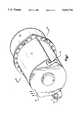
- FIG. 1schematically shows a perspective view of an inventive sorption device without preceding drying means for the ambient air taken in;
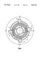
- FIG. 2shows a cross-section through the housing containing the digester adsorber elements, along line II--II of FIG. 1;
- FIG. 3shows a partial cross-section through the digester adsorber element of a sorption container
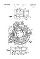
- FIG. 4shows a cross-section through the housing containing the condensor evaporator elements, along line IV--IV of FIG. 5 in a smaller scale;
- FIG. 5schematically shows a perspective view of an inventive sorption device with an additionally attached means for drying the supplied air
- FIG. 6shows a section along line VI--VI of FIG. 5;
- FIG. 7shows a cross-section through the housing containing the digester adsorber elements in the embodiment in accordance with FIG. 5, along line VII--VII, and
- FIG. 8shows the structure of a sorption container.
- the sorption device in accordance with the inventionconsists of two coaxially arranged housings 11 and 12 which are connected with each other.
- the housing 11surrounds the digester adsorber elements and can comprise 1/3 to 2/3 of the total length of the device, and in the embodiment described here it is about twice as long as the housing 12 surrounding the condensor evaporator elements.
- the lengthis optimized corresponding to the used substances.
- an air inlet 13is provided, into which ambient air is sucked through a radial flow fan and is passed through the housing to an air outlet 14.
- a gas burner 29Radially approximately opposite the fan the housing 11 comprises a gas burner 29 for heating the air.
- the introduction of the fuel gasis indicated at 15.
- the housing 12can have one central or two air inlets (not shown in FIG. 1).
- airis supplied via the passage 37 (FIG. 4, 5) at room temperature and is cooled during the evaporator phase. It leaves the associate outlet 34 and is used as cooling air, for instance for cooling the interior of a motor vehicle.
- airis likewise supplied at room temperature and is heated in the condensation phase. It leaves the outlet 35 as carrier of the waste heat, and during summer operation it is discharged to the outside, whereas during winter operation of the device it can be used for heating the air in a room.
- FIG. 2shows a cross-section through the housing 11 with the digester adsorber elements 16 of the sorption container disposed therein.
- the digester adsorber elementsconstitute elongated, flat hollow bodies and are bent at right angles to their longitudinal extension. They contain a zeolite, which by means of appropriate measures not represented in detail is distributed and stored such that it has the largest possible surface.
- the digester adsorber elementscan, for instance, be made of stainless steel sheet having a thickness of 0,2 mm, which on its inside is provided with a 2 mm thick layer of zeolite. On the outside, they have small steel sheet ribs, so that they are kept equally spaced in the assembled condition. The passages formed therebetween serve to guide the air.
- the hollow bodies extending in longitudinal direction of the housings 11, 12can be undulating in a direction transverse to their extension, where the maxima of the waves are oriented oppositely to prevent the very thin sheets from folding together under the influence of an external pressure.
- the outer ribs 17there can also be provided sheet metal bulges or the like.
- the digester adsorber elementsare arranged opposite to each other in the form of a circular ring, and they rotate as a whole in clockwise direction at a speed in the order of one rotation in 3 minutes.
- the digester adsorber elements having more or less a wing profileare spaced from each other through the ribs 17, which are disposed on their upper side and their lower side offset from each other, and between themselves constitute radial flow passages.
- the zeolite layer 49can have reinforcements formed by small sheet metal strips, through which it is avoided that the thin sheet metal sections are bent under the influence of different pressures, and which serve to improve the heat transfer.
- the digester adsorber elements 16pass through four regions, whose transitions are referred to as A, B, C and D in FIG. 2 and 4.
- theseare floating transitions, and the regions need not have the same size, but can deviate from the represented 90° sectioning.
- the region A-Bis the region of adsorption.
- the zeoliteadsorbs the steam by releasing heat, where the heat is released to the sections and is absorbed by the air introduced through the inlet 13.
- the steamis generated in the condensor evaporator elements and withdraws heat from the inflowing air in the housing 12.
- the region B-Cis the heating region, in which residual heat from the desorption region C-D is supplied to the sections.
- the region C-Dis the region of desorption.
- digester adsorber elementsare heated beyond the previous heating to about 300° C., in order to drive out the adsorbed water.
- the watercondenses in the condensor evaporator elements 30 (FIG. 4, 6, 8) by releasing the condensation heat to the second stream of air supplied via the inlet 33 in the housing 12.
- the region D-Ais the cooling region.
- the digester adsorber elements 16 heated for desorptionare cooled to be able to again adsorb water in the adjoining region A-B.
- the supply and dissipation of heat at the outer surfaces of the condensor adsorber elements 16is effected by a stream of air, which enters the housing 11 through the air inlet 13 and is passed on through a radial flow fan 18.
- the main flow direction of the airis counter-clockwise.
- the outer wall of the housing 11 and a cylindrical inner wall 19are spaced from the longitudinal sides of the digester adsorber elements, which are for instance sealed by roll welds, so that there are formed flow passages for the air, which extend in peripheral direction.
- longitudinally extending webs 20, 21, 22, 23, 24are formed, at which the stream of air is deflected radially to the inside.
- the cylindrical inner wall 19carries corresponding webs 25, 26, 27, 28 pointing to the outside, which are offset from the webs 20 to 24 in peripheral direction and guide the stream of air radially to the outside.
- the burner 29in particular a gas burner, which substantially extends along the length of the housing 11.
- This burnercan also be disposed adjacent the inner wall 19.
- the stream of air supplied through the fan 18follows the path indicated by arrows. In the region A-B it enters the housing and is guided by the webs 20, 21, for instance at (1), radially to the inside, and by the web 25, for instance at (2), again radially to the outside. In doing so it adsorbes the heat of adsorption produced in the digester adsorber elements 16.
- the airgets in contact with the digester adsorber elements, which have been heated in the desorption region C-D.
- the airis guided to the inside, at (3), and by the web 25 it is passed on counter-clockwise in peripheral direction. In doing so it absorbs further heat, while the heated digester adsorber elements are cooled down.
- the stream of airis again deflected to the outside, so that at (4) the air again gets into the outer flow passage.
- itis heated by the gas burner 29 and thus reaches a higher heat level than the digester adsorber elements 16.
- the air temperature in this regionis in the order of 300° C. or higher.
- the hot airis guided to the inside by the web 23, and at (7) it is again guided to the outside by the web 27 and dissipates its heat to the digester adsorber elements, in which therefore takes place the above described desorption.
- the airis deflected to the inside, and at (9) again to the outside to be finally discharged at (10). With this flow occurring in region C-B the air dissipates its residual heat to the digester adsorber elements 16, which come from the adsorption region A-B in a cooled condition and are thus preheated for desorption.
- the aironly has a slightly higher temperature than at the inlet 13, so that in the vicinity of the digester adsorber elements 16 there is only a minor loss of heat and thus of energy.
- FIG. 4shows a section through the housing 12 in a slightly reduced scale, in which there are disposed the condensor evaporator elements 30. Together with the digester adsorber elements 16 these hollow bodies each constitute a component extending in longitudinal direction of the housings 11, 12. At the transition from the housing 11 to the housing 12 the digester adsorber elements 16 are separated from the condensor evaporator elements 30 by an insulating wall designated with the reference numeral 31 in FIG. 6, by means of which the passage of the heat transfer medium is prevented in both directions. The digester adsorber elements 16 and the condensor evaporator elements 30 are thus rotating with each other about the same axis and are additionally fixed by the insulating wall 31.
- the housing 12comprises one or two air inlets 32, 33, which are not shown in FIG. 1.
- the housing 12comprises one or two air inlets 32, 33, which are not shown in FIG. 1.
- To the air inlet 32ambient air is supplied, which flows around the condensor evaporator elements 30 as indicated by the arrows and is discharged through the air outlet 34 as conditioned air.
- air at ambient temperatureflows into the air inlet 33 and leaves the housing 12 through the air outlet 35 via the passage 38.
- the inlet 32 and the outlet 34are located in the area A-B, which in the housing 11 constitutes the region of adsorption.
- this regionis the evaporator region, in which the liquid contained in the condensor evaporator elements 30 evaporates under a vacuum, absorbing heat from the ambient air.
- the boiling temperatureis for instance in the range of about -5° to +15° C.
- the heatis withdrawn from the air flowing around the condensor evaporator elements 30, which thus leaves the air outlet 34 at a lower temperature and can be used as conditioned air, for instance in a motor vehicle.
- the inlet 33 and the outlet 35cover a region which in direction of rotation of the condensor evaporator elements 30 approximately lies in the region C-D, in which in the housing 11 the desorption is effected by means of heating.
- the steam driven out of the digester adsorber elements 16condenses by releasing heat in the housing 12 in the condensor evaporator elements 30.
- the released heatis dissipated to the surrounding air, which therefore leaves the air outlet 35 at a higher temperature than when it is supplied through the air inlet 33.
- the stream of air discharged at 34serves to produce conditioned air, and at 35 the stream of air introduced at 33 is guided to the outside via the passage 38.
- the stream of air 33-35is used as hot air via a flap 43 for air-conditioning, whereas the stream of air 32-34 is discharged to the outside.
- the air supplycan constructively also be designed such that the ambient air is supplied through a common fan in a passage in which the air is divided for the two inlets 32 and 33.
- One possible field of application of the sorption device in accordance with the inventionis the cooling of the air in a room in air-conditioning systems.
- air-conditioning systemsWhen such systems are operated in regions with a high air humidity, as is for instance the case in some regions of the USA, there is the effect that the steam contained in the air condenses at the cooling surfaces and must be discharged as water. This effect is undesirable, because the entire heat of condensation is transferred to the cooling unit, which therefore must have an increased cooling capacity, which is not converted into a cooling of the air. The efficiency of the system is therefore distinctly deteriorated.
- the condensation of the air humiditycan be avoided, and the efficiency can thus be improved and can be maintained even with a high air humidity.
- This embodimentis illustrated in FIGS. 5 to 7.
- the principle of this embodimentconsists in the fact that the heat released in the condensor evaporator region, which has been discharged through the air outlet 35, is utilized for drying the ambient air to be cooled, which has been taken in.
- a room deviceswhich have a disk- or ring-shaped rotor rotating at a low speed, through which axially flows air to be dried.
- the flow passages of the rotorare coated with a hygroscopic salt that absorbs the air humidity.
- lithium chloridecan be used, for instance, which can possibly be provided on a support of zeolite.
- the rotorpasses through two regions. In the first region, the humid ambient air flows therethrough, thereby releasing its humidity to the salt. Through the second region there flows heated air, which has a lower relative humidity and again withdraws the humidity from the salt.
- such a rotor 36is mounted before the housing 11 comprising the digester adsorber elements 16. It is arranged coaxially with the digester adsorber elements 16 and the condensor evaporator elements 30 and rotates with the same speed as them, for instance with one rotation in the order of 3 minutes.
- the air inlet 32 and the air outlet 35 of the housing 12are connected by passages 37, 38 having openings 39, 40, which are disposed on one side of the rotor 36.
- the passage 38extends on the housing 11 in the region C, in which the desorption of the digester adsorber elements 16 is started by means of heating.
- the air heated by the burner 29flows through this region. A part of the heat contained in this air is dissipated through the wall of the housing 11 and via ribs 41 provided in the passage 38 to the air flowing through the passage 38.
- the airis therefore distinctly heated and withdraws the humidity from the salt of the rotor 36 by dissipating heat.
- flapsare indicated, which serve to close the passages 37 and 38 and at the same time open the inlet 32 and the outlet 35 to the outside via the passage 38.
- a fancan be provided within the device in the vicinity of the inlet 32.
- a fancan be provided in the vicinity of the inlet 33.
- the flapscan for instance be controlled automatically, such as hygrostatically or thermally or mechanically by hand, and they allow the drying of air to be effected only with a correspondingly high relative humidity, so as to avoid an unnecessary actuation and heating of the salt rotor.
- FIG. 8schematically shows the structure of a sorption container consisting of digester adsorber element 16 and condensor evaporator element 30.
- the sorption containerconsists of two deep-drawn thin sheets 44, 45 having a wall thickness of 0,2 mm or less.
- recesses 46, 47have been formed in the upper sheet 44 in the drawing.
- the sheetsare coated at their inside with a supporting material 48, for instance with glass fiber.
- the digester adsorber elementis separated from the condensor evaporator element by a charging gap 50.
- the zeolite material 49is incorporated in the supporting material 48.
- the two sheets 44, 45were manufactured separately, then placed side by side in the illustrated flat condition and welded together at the peripheral edges by means of a rolling seam 51.
- the curvature in the form of an involutewhich is shown in FIG. 3 and promotes the air flow, can be made during the step of combining and connecting because of the low wall thicknesses.
- a possible field of application of the inventive sorption deviceis the cooling of the passenger compartment of motor vehicles.
- a heat exchangercan be provided instead of the gas burner 29, which in the sorption device appropriately utilizes the heat contained in the exhaust gases.
- the exhaust gasescan be directly introduced in section C-D.
- a further field of applicationare air-conditioning devices in camping cars and mobile homes, where the devices can be accommodated in the roof.
- the heating of the digester adsorber elementcan selectively be effected with gas or with current.
- the sorption device in accordance with the inventioncan finally also be operated as a heat pump and be used both for heating and for cooling.
- a major advantage of the device in accordance with the inventionconsists in the fact that the airflow is repeatedly guided through the flow passages from the outside to the inside and vice versa, where in the digester adsorber region an improved utilization of heat, and in the condensor evaporator region an intensive heat transfer are effected.
- the heat to be supplied to the digester adsorber regioncan therefore be reduced, so that the energy requirement is reduced.
- the advantageous construction of the digester adsorber elementsprovides for an improved heat distribution along the length and the cross-section, and thus for an improved efficiency.
Landscapes
- Engineering & Computer Science (AREA)
- Mechanical Engineering (AREA)
- General Engineering & Computer Science (AREA)
- Life Sciences & Earth Sciences (AREA)
- Sustainable Development (AREA)
- Chemical & Material Sciences (AREA)
- Combustion & Propulsion (AREA)
- Physics & Mathematics (AREA)
- Thermal Sciences (AREA)
- Sorption Type Refrigeration Machines (AREA)
- Air-Conditioning Room Units, And Self-Contained Units In General (AREA)
Abstract
Description
Claims (31)
Applications Claiming Priority (2)
| Application Number | Priority Date | Filing Date | Title |
|---|---|---|---|
| DE4233062ADE4233062A1 (en) | 1992-10-01 | 1992-10-01 | Sorption apparatus for use in a cooling system |
| DE4233062.9 | 1992-10-01 |
Publications (1)
| Publication Number | Publication Date |
|---|---|
| US5431716Atrue US5431716A (en) | 1995-07-11 |
Family
ID=6469418
Family Applications (1)
| Application Number | Title | Priority Date | Filing Date |
|---|---|---|---|
| US08/129,988Expired - Fee RelatedUS5431716A (en) | 1992-10-01 | 1993-09-30 | Sorption device |
Country Status (4)
| Country | Link |
|---|---|
| US (1) | US5431716A (en) |
| EP (1) | EP0590443B1 (en) |
| JP (1) | JP3339935B2 (en) |
| DE (2) | DE4233062A1 (en) |
Cited By (38)
| Publication number | Priority date | Publication date | Assignee | Title |
|---|---|---|---|---|
| US5817167A (en)* | 1996-08-21 | 1998-10-06 | Des Champs Laboratories Incorporated | Desiccant based dehumidifier |
| US5878590A (en)* | 1998-02-25 | 1999-03-09 | General Motors Corporation | Dehumidifying mechanism for auto air conditioner with improved space utilization and thermal efficiency |
| US6056804A (en)* | 1997-06-30 | 2000-05-02 | Questor Industries Inc. | High frequency rotary pressure swing adsorption apparatus |
| EP0853219A3 (en)* | 1997-01-08 | 2000-11-02 | The BOC Group plc | Fluid chilling apparatus |
| WO2001022010A1 (en)* | 1999-09-21 | 2001-03-29 | University Of Warwick | Thermal regenerative sorption device |
| US20020004157A1 (en)* | 1998-09-14 | 2002-01-10 | Keefer Bowie G. | Electrical current generation system |
| US6348086B1 (en)* | 2000-02-16 | 2002-02-19 | 3M Innovative Properties Company | Combination blower wheel and filter cartridge system for HVAC applications |
| US6406523B1 (en)* | 1999-06-09 | 2002-06-18 | Questair Technologies, Inc. | Rotary pressure swing adsorption apparatus |
| WO2002047797A1 (en)* | 2000-12-11 | 2002-06-20 | Questair Technologies, Inc. | Psa with adsorbents sensitive to contaminants |
| US6447583B1 (en) | 1999-06-04 | 2002-09-10 | Flair Corporation | Rotating drum adsorber process and system |
| US20020127442A1 (en)* | 2000-12-08 | 2002-09-12 | Connor Denis J. | Methods and apparatuses for gas separation by pressure swing adsorption with partial gas product feed to fuel cell power source |
| US6451095B1 (en)* | 1997-12-01 | 2002-09-17 | Questair Technologies, Inc. | Modular pressure swing adsorption apparatus |
| US20020142208A1 (en)* | 2000-10-30 | 2002-10-03 | Keefer Bowie G. | Energy efficient gas separation for fuel cells |
| US20020170436A1 (en)* | 2001-01-05 | 2002-11-21 | Keefer Bowie G. | Adsorbent coating compositions, laminates and adsorber elements comprising such compositions and methods for their manufacture and use |
| US6488747B1 (en)* | 1999-06-10 | 2002-12-03 | Questair Technologies, Inc. | Pressure swing adsorption with axial or centrifugal compression machinery |
| US6514319B2 (en)* | 1999-12-09 | 2003-02-04 | Questair Technologies Inc. | Life support oxygen concentrator |
| US20030143448A1 (en)* | 2000-10-30 | 2003-07-31 | Questair Technologies Inc. | High temperature fuel cell power plant |
| US20040005492A1 (en)* | 2002-03-14 | 2004-01-08 | Questair Technologies, Inc. | Hydrogen recycle for solid oxide fuel cell |
| US20040011198A1 (en)* | 2002-03-14 | 2004-01-22 | Questair Technologies, Inc. | Gas separation by combined pressure swing and displacement purge |
| USRE38493E1 (en) | 1996-04-24 | 2004-04-13 | Questair Technologies Inc. | Flow regulated pressure swing adsorption system |
| US6770120B2 (en)* | 2002-05-01 | 2004-08-03 | Praxair Technology, Inc. | Radial adsorption gas separation apparatus and method of use |
| US20040197612A1 (en)* | 2003-02-26 | 2004-10-07 | Questair Technologies Inc. | Hydrogen recycle for high temperature fuel cells |
| US20050061023A1 (en)* | 1997-07-14 | 2005-03-24 | Dometic Ag | Sorption unit for an air conditioning apparatus |
| US20050145111A1 (en)* | 1997-12-01 | 2005-07-07 | Questair Technologies, Inc. | Modular pressure swing adsorption apparatus |
| US20050183572A1 (en)* | 1999-12-09 | 2005-08-25 | Questair Technologies Inc. | Life support oxygen concentrator |
| US20050213514A1 (en)* | 2004-03-23 | 2005-09-29 | Ching-Fong Su | Estimating and managing network traffic |
| US20050284291A1 (en)* | 2004-06-29 | 2005-12-29 | Questair Technologies Inc., | Adsorptive separation of gas streams |
| US20060048648A1 (en)* | 2004-08-20 | 2006-03-09 | Questair Technologies Inc. | Parallel passage contactor structure |
| US20060090646A1 (en)* | 2004-11-04 | 2006-05-04 | Questair Technologies Inc. | Adsorbent material for selective adsorption of carbon monoxide and unsaturated hydrocarbons |
| US20060169142A1 (en)* | 2005-01-07 | 2006-08-03 | Questair Technologies Inc. | Engineered adsorbent structures for kinetic separation |
| US20060182680A1 (en)* | 2000-10-27 | 2006-08-17 | Questair Technologies Inc. | Systems and processes for providing hydrogen to fuel cells |
| US7285350B2 (en) | 2002-09-27 | 2007-10-23 | Questair Technologies Inc. | Enhanced solid oxide fuel cell systems |
| US20070261551A1 (en)* | 2004-11-05 | 2007-11-15 | Sawada James A | Separation Of Carbon Dioxide From Other Gases |
| US20120152116A1 (en)* | 2010-12-16 | 2012-06-21 | Prometheus Technologies, Llc | Rotary fluid processing systems and associated methods |
| KR101419384B1 (en) | 2013-02-28 | 2014-07-15 | 주식회사 멘도타 | Radial Multi-pass Rotary Chiller |
| WO2019169497A1 (en) | 2018-03-07 | 2019-09-12 | Enersion Inc. | Adsorption-based heat pump |
| USD1002676S1 (en) | 2019-08-30 | 2023-10-24 | Dometic Sweden Ab | Appliance |
| USD1026969S1 (en) | 2020-08-31 | 2024-05-14 | Dometic Sweden Ab | Refrigerator |
Families Citing this family (5)
| Publication number | Priority date | Publication date | Assignee | Title |
|---|---|---|---|---|
| JPH11501394A (en)* | 1995-12-29 | 1999-02-02 | エレクトロラックス・レジャー・アプライアンシーズ・アー・ゲー | Sorption device |
| DE19730136A1 (en) | 1997-07-14 | 1999-01-21 | Electrolux Leisure Appliances | Air conditioning device and its components |
| DE19818807B4 (en)* | 1998-04-27 | 2007-03-22 | Behr Gmbh & Co. Kg | Sorption device, in particular for the air conditioning of vehicle interiors |
| RU2169888C2 (en)* | 1999-03-10 | 2001-06-27 | ГосНИИ НПО "Луч" | Metallohydride refrigerator |
| CN104457050B (en)* | 2014-06-09 | 2016-12-07 | 陈国锋 | Centrifugal refrierator in a kind of rotating boosting |
Citations (15)
| Publication number | Priority date | Publication date | Assignee | Title |
|---|---|---|---|---|
| US2286920A (en)* | 1939-12-21 | 1942-06-16 | E B Miller Engineering Company | Air conditioning system |
| US2639000A (en)* | 1950-03-01 | 1953-05-19 | Sutcliffe Speakman & Company L | Rotating bed adsorber |
| US2662607A (en)* | 1950-07-22 | 1953-12-15 | Milton J Guiberteau | Rotating bed adsorber |
| US2680492A (en)* | 1951-06-22 | 1954-06-08 | Roger S Kopp | Air dehydration unit |
| US3828528A (en)* | 1971-02-23 | 1974-08-13 | Gas Dev Corp | Adiabatic saturation cooling machine |
| US4012206A (en)* | 1972-12-02 | 1977-03-15 | Gas Developments Corporation | Air cleaning adsorption process |
| SU794310A1 (en)* | 1978-12-18 | 1981-01-07 | Предприятие П/Я А-7731 | Continuous-action air dryer |
| US4497361A (en)* | 1981-06-15 | 1985-02-05 | Hajicek David J | Regenerative heat and humidity exchanging apparatus |
| EP0151237A2 (en)* | 1983-11-28 | 1985-08-14 | ZEO-TECH Zeolith Technologie GmbH | Continuously working sorption type apparatus and method for its operation |
| US4594860A (en)* | 1984-09-24 | 1986-06-17 | American Solar King Corporation | Open cycle desiccant air-conditioning system and components thereof |
| US4700550A (en)* | 1986-03-10 | 1987-10-20 | Rhodes Barry V | Enthalpic heat pump desiccant air conditioning system |
| US4711097A (en)* | 1986-10-24 | 1987-12-08 | Ferdinand Besik | Apparatus for sorption dehumidification and cooling of moist air |
| US4769053A (en)* | 1987-03-26 | 1988-09-06 | Semco Mfg., Inc. | High efficiency sensible and latent heat exchange media with selected transfer for a total energy recovery wheel |
| US5170633A (en)* | 1991-06-24 | 1992-12-15 | Amsted Industries Incorporated | Desiccant based air conditioning system |
| US5242473A (en)* | 1988-09-22 | 1993-09-07 | Unico Kogyo Kabushiki Kaisha | Apparatus for dehumidifying gas |
Family Cites Families (8)
| Publication number | Priority date | Publication date | Assignee | Title |
|---|---|---|---|---|
| US4169362A (en)* | 1977-03-24 | 1979-10-02 | Institute Of Gas Technology | Solid adsorption air conditioning apparatus |
| GB8308135D0 (en)* | 1983-03-24 | 1983-05-05 | Ici Plc | Centrifugal heat pump |
| US4574874A (en)* | 1983-04-07 | 1986-03-11 | Pan Tech Management Corp. | Chemisorption air conditioner |
| DE3509564A1 (en)* | 1985-03-16 | 1986-09-18 | Thomas Dipl.-Ing. 7500 Karlsruhe Föllinger | Apparatus for carrying out adsorption, desorption and internal heat exchange |
| SU1280280A1 (en)* | 1985-07-04 | 1986-12-30 | Центральное Проектно-Конструкторское И Технологическое Бюро Научного Приборостроения Ан Узсср | Generator-adsorber of solar-energy cooler |
| SU1719818A1 (en)* | 1989-08-22 | 1992-03-15 | Институт Тепло-И Массообмена Им.А.В.Лыкова | Generator-adsorber of batch adsorption refrigerator |
| KR930004389B1 (en)* | 1991-01-17 | 1993-05-27 | 한국 과학기술연구원 | Heat-pump |
| DE4121131A1 (en)* | 1991-06-26 | 1993-01-07 | Zeolith Tech | SORPTION AGENT CONTAINER AND SORPTION METHOD WITH REGENERATIVE HEAT EXCHANGER |
- 1992
- 1992-10-01DEDE4233062Apatent/DE4233062A1/ennot_activeWithdrawn
- 1993
- 1993-09-17DEDE59304661Tpatent/DE59304661D1/ennot_activeExpired - Fee Related
- 1993-09-17EPEP93115007Apatent/EP0590443B1/ennot_activeExpired - Lifetime
- 1993-09-30USUS08/129,988patent/US5431716A/ennot_activeExpired - Fee Related
- 1993-10-01JPJP24650693Apatent/JP3339935B2/ennot_activeExpired - Fee Related
Patent Citations (15)
| Publication number | Priority date | Publication date | Assignee | Title |
|---|---|---|---|---|
| US2286920A (en)* | 1939-12-21 | 1942-06-16 | E B Miller Engineering Company | Air conditioning system |
| US2639000A (en)* | 1950-03-01 | 1953-05-19 | Sutcliffe Speakman & Company L | Rotating bed adsorber |
| US2662607A (en)* | 1950-07-22 | 1953-12-15 | Milton J Guiberteau | Rotating bed adsorber |
| US2680492A (en)* | 1951-06-22 | 1954-06-08 | Roger S Kopp | Air dehydration unit |
| US3828528A (en)* | 1971-02-23 | 1974-08-13 | Gas Dev Corp | Adiabatic saturation cooling machine |
| US4012206A (en)* | 1972-12-02 | 1977-03-15 | Gas Developments Corporation | Air cleaning adsorption process |
| SU794310A1 (en)* | 1978-12-18 | 1981-01-07 | Предприятие П/Я А-7731 | Continuous-action air dryer |
| US4497361A (en)* | 1981-06-15 | 1985-02-05 | Hajicek David J | Regenerative heat and humidity exchanging apparatus |
| EP0151237A2 (en)* | 1983-11-28 | 1985-08-14 | ZEO-TECH Zeolith Technologie GmbH | Continuously working sorption type apparatus and method for its operation |
| US4594860A (en)* | 1984-09-24 | 1986-06-17 | American Solar King Corporation | Open cycle desiccant air-conditioning system and components thereof |
| US4700550A (en)* | 1986-03-10 | 1987-10-20 | Rhodes Barry V | Enthalpic heat pump desiccant air conditioning system |
| US4711097A (en)* | 1986-10-24 | 1987-12-08 | Ferdinand Besik | Apparatus for sorption dehumidification and cooling of moist air |
| US4769053A (en)* | 1987-03-26 | 1988-09-06 | Semco Mfg., Inc. | High efficiency sensible and latent heat exchange media with selected transfer for a total energy recovery wheel |
| US5242473A (en)* | 1988-09-22 | 1993-09-07 | Unico Kogyo Kabushiki Kaisha | Apparatus for dehumidifying gas |
| US5170633A (en)* | 1991-06-24 | 1992-12-15 | Amsted Industries Incorporated | Desiccant based air conditioning system |
Cited By (68)
| Publication number | Priority date | Publication date | Assignee | Title |
|---|---|---|---|---|
| USRE40006E1 (en)* | 1996-04-24 | 2008-01-22 | Questair Technologies Inc. | Flow regulated pressure swing adsorption system |
| USRE38493E1 (en) | 1996-04-24 | 2004-04-13 | Questair Technologies Inc. | Flow regulated pressure swing adsorption system |
| US5817167A (en)* | 1996-08-21 | 1998-10-06 | Des Champs Laboratories Incorporated | Desiccant based dehumidifier |
| EP0853219A3 (en)* | 1997-01-08 | 2000-11-02 | The BOC Group plc | Fluid chilling apparatus |
| US6056804A (en)* | 1997-06-30 | 2000-05-02 | Questor Industries Inc. | High frequency rotary pressure swing adsorption apparatus |
| US7065981B2 (en) | 1997-07-14 | 2006-06-27 | Dometic Ag | Sorption unit for an air conditioning apparatus |
| US20050061023A1 (en)* | 1997-07-14 | 2005-03-24 | Dometic Ag | Sorption unit for an air conditioning apparatus |
| US20050145111A1 (en)* | 1997-12-01 | 2005-07-07 | Questair Technologies, Inc. | Modular pressure swing adsorption apparatus |
| US7094275B2 (en) | 1997-12-01 | 2006-08-22 | Questair Technologies, Inc. | Modular pressure swing adsorption apparatus |
| US6451095B1 (en)* | 1997-12-01 | 2002-09-17 | Questair Technologies, Inc. | Modular pressure swing adsorption apparatus |
| US5878590A (en)* | 1998-02-25 | 1999-03-09 | General Motors Corporation | Dehumidifying mechanism for auto air conditioner with improved space utilization and thermal efficiency |
| USRE38181E1 (en) | 1998-02-25 | 2003-07-15 | Delphi Technologies, Inc. | Dehumidifying mechanism for auto air conditioner with improved space utilization and thermal efficiency |
| US20020004157A1 (en)* | 1998-09-14 | 2002-01-10 | Keefer Bowie G. | Electrical current generation system |
| US7758988B2 (en) | 1998-09-14 | 2010-07-20 | Xebec Adsorption Inc. | System that includes a fuel cell and an oxygen gas delivery system |
| US6921597B2 (en) | 1998-09-14 | 2005-07-26 | Questair Technologies Inc. | Electrical current generation system |
| US20060257708A1 (en)* | 1998-09-14 | 2006-11-16 | Questair Technologies Inc. | Electrical current generation system |
| US20030157390A1 (en)* | 1998-09-14 | 2003-08-21 | Questair Technologies, Inc. | Electrical current generation system |
| US6527836B1 (en) | 1999-06-04 | 2003-03-04 | Flair Corporation | Rotating drum adsorber process and system |
| US6447583B1 (en) | 1999-06-04 | 2002-09-10 | Flair Corporation | Rotating drum adsorber process and system |
| US6406523B1 (en)* | 1999-06-09 | 2002-06-18 | Questair Technologies, Inc. | Rotary pressure swing adsorption apparatus |
| US6488747B1 (en)* | 1999-06-10 | 2002-12-03 | Questair Technologies, Inc. | Pressure swing adsorption with axial or centrifugal compression machinery |
| US6629432B1 (en) | 1999-09-21 | 2003-10-07 | University Of Warwick | Thermal regenerative sorption device |
| WO2001022010A1 (en)* | 1999-09-21 | 2001-03-29 | University Of Warwick | Thermal regenerative sorption device |
| US7250073B2 (en) | 1999-12-09 | 2007-07-31 | Questair Technologies, Inc. | Life support oxygen concentrator |
| US6514319B2 (en)* | 1999-12-09 | 2003-02-04 | Questair Technologies Inc. | Life support oxygen concentrator |
| US20030196550A1 (en)* | 1999-12-09 | 2003-10-23 | Questair Technologies Inc. | Life support oxygen concentrator |
| US20050183572A1 (en)* | 1999-12-09 | 2005-08-25 | Questair Technologies Inc. | Life support oxygen concentrator |
| US6348086B1 (en)* | 2000-02-16 | 2002-02-19 | 3M Innovative Properties Company | Combination blower wheel and filter cartridge system for HVAC applications |
| US7674539B2 (en) | 2000-10-27 | 2010-03-09 | Xebec Adsorption Inc. | Systems and processes for providing hydrogen to fuel cells |
| US20060182680A1 (en)* | 2000-10-27 | 2006-08-17 | Questair Technologies Inc. | Systems and processes for providing hydrogen to fuel cells |
| US7097925B2 (en) | 2000-10-30 | 2006-08-29 | Questair Technologies Inc. | High temperature fuel cell power plant |
| US7087331B2 (en) | 2000-10-30 | 2006-08-08 | Questair Technologies Inc. | Energy efficient gas separation for fuel cells |
| US20020142208A1 (en)* | 2000-10-30 | 2002-10-03 | Keefer Bowie G. | Energy efficient gas separation for fuel cells |
| US20030143448A1 (en)* | 2000-10-30 | 2003-07-31 | Questair Technologies Inc. | High temperature fuel cell power plant |
| US20020127442A1 (en)* | 2000-12-08 | 2002-09-12 | Connor Denis J. | Methods and apparatuses for gas separation by pressure swing adsorption with partial gas product feed to fuel cell power source |
| US6866950B2 (en) | 2000-12-08 | 2005-03-15 | Questair Technologies Inc. | Methods and apparatuses for gas separation by pressure swing adsorption with partial gas product feed to fuel cell power source |
| US7160367B2 (en) | 2000-12-11 | 2007-01-09 | Questair Technologies, Inc. | PSA with adsorbents sensitive to contaminants |
| CN100371051C (en)* | 2000-12-11 | 2008-02-27 | 探索空气技术公司 | PSA with adsorbents sensitive to contaminants |
| US7037358B2 (en) | 2000-12-11 | 2006-05-02 | The Boc Group, Inc. | PSA with adsorbents sensitive to contaminants |
| WO2002047797A1 (en)* | 2000-12-11 | 2002-06-20 | Questair Technologies, Inc. | Psa with adsorbents sensitive to contaminants |
| US20040261618A1 (en)* | 2000-12-11 | 2004-12-30 | Questair Technologies Inc. | PSA with adsorbents sensitive to contaminants |
| US7300905B2 (en) | 2001-01-05 | 2007-11-27 | Questair Technologies Inc. | Methods for their manufacture of adsorbent |
| US20020170436A1 (en)* | 2001-01-05 | 2002-11-21 | Keefer Bowie G. | Adsorbent coating compositions, laminates and adsorber elements comprising such compositions and methods for their manufacture and use |
| US7387849B2 (en) | 2002-03-14 | 2008-06-17 | Questair Technologies Inc. | Hydrogen recycle for solid oxide fuel cell |
| US20040005492A1 (en)* | 2002-03-14 | 2004-01-08 | Questair Technologies, Inc. | Hydrogen recycle for solid oxide fuel cell |
| US20040011198A1 (en)* | 2002-03-14 | 2004-01-22 | Questair Technologies, Inc. | Gas separation by combined pressure swing and displacement purge |
| US6902602B2 (en) | 2002-03-14 | 2005-06-07 | Questair Technologies Inc. | Gas separation by combined pressure swing and displacement purge |
| US6770120B2 (en)* | 2002-05-01 | 2004-08-03 | Praxair Technology, Inc. | Radial adsorption gas separation apparatus and method of use |
| US7285350B2 (en) | 2002-09-27 | 2007-10-23 | Questair Technologies Inc. | Enhanced solid oxide fuel cell systems |
| US20040197612A1 (en)* | 2003-02-26 | 2004-10-07 | Questair Technologies Inc. | Hydrogen recycle for high temperature fuel cells |
| US20050213514A1 (en)* | 2004-03-23 | 2005-09-29 | Ching-Fong Su | Estimating and managing network traffic |
| US7189280B2 (en) | 2004-06-29 | 2007-03-13 | Questair Technologies Inc. | Adsorptive separation of gas streams |
| US20050284291A1 (en)* | 2004-06-29 | 2005-12-29 | Questair Technologies Inc., | Adsorptive separation of gas streams |
| US20060048648A1 (en)* | 2004-08-20 | 2006-03-09 | Questair Technologies Inc. | Parallel passage contactor structure |
| US20060090646A1 (en)* | 2004-11-04 | 2006-05-04 | Questair Technologies Inc. | Adsorbent material for selective adsorption of carbon monoxide and unsaturated hydrocarbons |
| US20070261551A1 (en)* | 2004-11-05 | 2007-11-15 | Sawada James A | Separation Of Carbon Dioxide From Other Gases |
| US7828877B2 (en) | 2004-11-05 | 2010-11-09 | Xebec Adsorption, Inc. | Separation of carbon dioxide from other gases |
| US20060169142A1 (en)* | 2005-01-07 | 2006-08-03 | Questair Technologies Inc. | Engineered adsorbent structures for kinetic separation |
| US7645324B2 (en) | 2005-01-07 | 2010-01-12 | Xebec Adsorption Inc. | Engineered adsorbent structures for kinetic separation |
| US9302215B2 (en) | 2010-12-16 | 2016-04-05 | Prometheus Technologies, Llc | Rotary fluid processing systems and associated methods |
| US8852328B2 (en) | 2010-12-16 | 2014-10-07 | Prometheus Technologies, Llc | Rotary fluid processing systems and associated methods |
| US20120152116A1 (en)* | 2010-12-16 | 2012-06-21 | Prometheus Technologies, Llc | Rotary fluid processing systems and associated methods |
| KR101419384B1 (en) | 2013-02-28 | 2014-07-15 | 주식회사 멘도타 | Radial Multi-pass Rotary Chiller |
| WO2019169497A1 (en) | 2018-03-07 | 2019-09-12 | Enersion Inc. | Adsorption-based heat pump |
| EP4603763A2 (en) | 2018-03-07 | 2025-08-20 | Enersion Inc. | Adsorption-based heat pump |
| USD1002676S1 (en) | 2019-08-30 | 2023-10-24 | Dometic Sweden Ab | Appliance |
| USD1026969S1 (en) | 2020-08-31 | 2024-05-14 | Dometic Sweden Ab | Refrigerator |
| USD1053913S1 (en) | 2020-08-31 | 2024-12-10 | Dometic Sweden Ab | Refrigerator |
Also Published As
| Publication number | Publication date |
|---|---|
| DE4233062A1 (en) | 1994-04-07 |
| DE59304661D1 (en) | 1997-01-16 |
| JPH06241495A (en) | 1994-08-30 |
| EP0590443A1 (en) | 1994-04-06 |
| JP3339935B2 (en) | 2002-10-28 |
| EP0590443B1 (en) | 1996-12-04 |
Similar Documents
| Publication | Publication Date | Title |
|---|---|---|
| US5431716A (en) | Sorption device | |
| USRE38181E1 (en) | Dehumidifying mechanism for auto air conditioner with improved space utilization and thermal efficiency | |
| US6739142B2 (en) | Membrane desiccation heat pump | |
| US6205805B1 (en) | Motor vehicle dehumidifier with drying agent and drying agent regenerative control | |
| US4660629A (en) | Continuously acting adsorption devices and process for their operation | |
| US5817167A (en) | Desiccant based dehumidifier | |
| US7143589B2 (en) | Sorption cooling systems, their use in automotive cooling applications and methods relating to the same | |
| US5771707A (en) | Unitary heat exchanger for the air-to-air transfer of water vapor and sensible heat | |
| US5404728A (en) | Sorption agent container device and sorption method with a regenerative heat exchange | |
| EP0140954B1 (en) | Chemisorption apparatus | |
| US6361588B1 (en) | Selective permeability energy recovery device | |
| US6629432B1 (en) | Thermal regenerative sorption device | |
| CN110678698B (en) | Air conditioning method and device | |
| JP6432462B2 (en) | Absorption heat pump device | |
| JP4919498B2 (en) | Air conditioning system | |
| US5941093A (en) | Sorption device | |
| JP2015010718A (en) | Desiccant dehumidifier, desiccant air conditioning system, and desiccant rotor | |
| US20240077218A1 (en) | Dehumidification unit and desiccant drum therein | |
| JP6578796B2 (en) | Absorption heat pump device | |
| JP2024034493A (en) | Moisture absorption cartridge and automobile air conditioner using the same | |
| WO2019087695A1 (en) | Adsorption type refrigeration device | |
| JP4161512B2 (en) | Dehumidifier | |
| WO2001029487A1 (en) | Cooling apparatus | |
| JPS63161366A (en) | chemical heat converter | |
| JPH09236355A (en) | Chemical heat pump |
Legal Events
| Date | Code | Title | Description |
|---|---|---|---|
| AS | Assignment | Owner name:ELECTROLUX LEISURE APPLIANCES AG, SWITZERLAND Free format text:ASSIGNMENT OF ASSIGNORS INTEREST;ASSIGNOR:EBBESON, BENGT;REEL/FRAME:006836/0201 Effective date:19931221 | |
| FEPP | Fee payment procedure | Free format text:PAYOR NUMBER ASSIGNED (ORIGINAL EVENT CODE: ASPN); ENTITY STATUS OF PATENT OWNER: LARGE ENTITY | |
| CC | Certificate of correction | ||
| FPAY | Fee payment | Year of fee payment:4 | |
| FPAY | Fee payment | Year of fee payment:8 | |
| REMI | Maintenance fee reminder mailed | ||
| AS | Assignment | Owner name:DOMETIC AG, SWITZERLAND Free format text:CHANGE OF NAME;ASSIGNOR:ELECTROLUX LEISURE APPLIANCE AG;REEL/FRAME:015962/0931 Effective date:20040422 | |
| AS | Assignment | Owner name:DOMETIC AG, SWITZERLAND Free format text:CORRECTIVE CHANGE OF DOCUMENT TO CORRECT PATENT NO. 5,436,716 ON REEL 015962 FRAME 0931. ASSIGNOR HEREBY CONFIRMS THE ASSIGNMENT OF THE ENTIRE INTEREST.;ASSIGNOR:ELECTROLUX LEISURE APPLICANCES AG;REEL/FRAME:016345/0061 Effective date:20040422 | |
| REMI | Maintenance fee reminder mailed | ||
| LAPS | Lapse for failure to pay maintenance fees | ||
| STCH | Information on status: patent discontinuation | Free format text:PATENT EXPIRED DUE TO NONPAYMENT OF MAINTENANCE FEES UNDER 37 CFR 1.362 | |
| FP | Lapsed due to failure to pay maintenance fee | Effective date:20070711 |