US5431648A - Radiating device for hyperthermia - Google Patents
Radiating device for hyperthermiaDownload PDFInfo
- Publication number
- US5431648A US5431648AUS08/232,190US23219094AUS5431648AUS 5431648 AUS5431648 AUS 5431648AUS 23219094 AUS23219094 AUS 23219094AUS 5431648 AUS5431648 AUS 5431648A
- Authority
- US
- United States
- Prior art keywords
- catheter
- thermocouples
- bladder
- antenna
- power supply
- Prior art date
- Legal status (The legal status is an assumption and is not a legal conclusion. Google has not performed a legal analysis and makes no representation as to the accuracy of the status listed.)
- Ceased
Links
- 206010020843HyperthermiaDiseases0.000titleclaimsdescription6
- 230000036031hyperthermiaEffects0.000titleclaimsdescription6
- 239000007788liquidSubstances0.000claimsabstractdescription35
- 239000012530fluidSubstances0.000claimsabstractdescription9
- 206010028980NeoplasmDiseases0.000abstractdescription6
- 230000005855radiationEffects0.000abstractdescription6
- 239000004033plasticSubstances0.000abstractdescription5
- 210000000056organAnatomy0.000abstractdescription4
- 238000002560therapeutic procedureMethods0.000abstract1
- 210000003932urinary bladderAnatomy0.000description35
- 239000002184metalSubstances0.000description10
- 230000003750conditioning effectEffects0.000description8
- 238000010438heat treatmentMethods0.000description6
- 239000004020conductorSubstances0.000description5
- 239000007789gasSubstances0.000description4
- 238000011144upstream manufacturingMethods0.000description4
- 230000035515penetrationEffects0.000description3
- 210000003708urethraAnatomy0.000description3
- 238000004891communicationMethods0.000description2
- 239000000243solutionSubstances0.000description2
- 210000002700urineAnatomy0.000description2
- 208000027418Wounds and injuryDiseases0.000description1
- 239000007864aqueous solutionSubstances0.000description1
- 230000015572biosynthetic processEffects0.000description1
- 238000009954braidingMethods0.000description1
- 201000011510cancerDiseases0.000description1
- 238000006243chemical reactionMethods0.000description1
- 238000010276constructionMethods0.000description1
- 238000001816coolingMethods0.000description1
- 238000007872degassingMethods0.000description1
- 238000010586diagramMethods0.000description1
- 230000000694effectsEffects0.000description1
- 231100000518lethalToxicity0.000description1
- 230000001665lethal effectEffects0.000description1
- 238000004519manufacturing processMethods0.000description1
- 230000001151other effectEffects0.000description1
- 238000013021overheatingMethods0.000description1
- 230000001575pathological effectEffects0.000description1
- -1polytetrafluoroethylenePolymers0.000description1
- 229920001343polytetrafluoroethylenePolymers0.000description1
- 239000004810polytetrafluoroethyleneSubstances0.000description1
- 230000001681protective effectEffects0.000description1
- 238000005086pumpingMethods0.000description1
- 230000003014reinforcing effectEffects0.000description1
- 239000000523sampleSubstances0.000description1
- 229910001220stainless steelInorganic materials0.000description1
- 239000000126substanceSubstances0.000description1
- 230000005676thermoelectric effectEffects0.000description1
- 230000007704transitionEffects0.000description1
- 230000001173tumoral effectEffects0.000description1
- 238000004804windingMethods0.000description1
Images


Classifications
- A—HUMAN NECESSITIES
- A61—MEDICAL OR VETERINARY SCIENCE; HYGIENE
- A61B—DIAGNOSIS; SURGERY; IDENTIFICATION
- A61B18/00—Surgical instruments, devices or methods for transferring non-mechanical forms of energy to or from the body
- A61B18/18—Surgical instruments, devices or methods for transferring non-mechanical forms of energy to or from the body by applying electromagnetic radiation, e.g. microwaves
- A—HUMAN NECESSITIES
- A61—MEDICAL OR VETERINARY SCIENCE; HYGIENE
- A61F—FILTERS IMPLANTABLE INTO BLOOD VESSELS; PROSTHESES; DEVICES PROVIDING PATENCY TO, OR PREVENTING COLLAPSING OF, TUBULAR STRUCTURES OF THE BODY, e.g. STENTS; ORTHOPAEDIC, NURSING OR CONTRACEPTIVE DEVICES; FOMENTATION; TREATMENT OR PROTECTION OF EYES OR EARS; BANDAGES, DRESSINGS OR ABSORBENT PADS; FIRST-AID KITS
- A61F7/00—Heating or cooling appliances for medical or therapeutic treatment of the human body
- A61F7/12—Devices for heating or cooling internal body cavities
- A61F7/123—Devices for heating or cooling internal body cavities using a flexible balloon containing the thermal element
- A—HUMAN NECESSITIES
- A61—MEDICAL OR VETERINARY SCIENCE; HYGIENE
- A61N—ELECTROTHERAPY; MAGNETOTHERAPY; RADIATION THERAPY; ULTRASOUND THERAPY
- A61N5/00—Radiation therapy
- A61N5/02—Radiation therapy using microwaves
- A61N5/04—Radiators for near-field treatment
- A—HUMAN NECESSITIES
- A61—MEDICAL OR VETERINARY SCIENCE; HYGIENE
- A61N—ELECTROTHERAPY; MAGNETOTHERAPY; RADIATION THERAPY; ULTRASOUND THERAPY
- A61N5/00—Radiation therapy
- A61N5/02—Radiation therapy using microwaves
- A61N5/04—Radiators for near-field treatment
- A61N5/045—Radiators for near-field treatment specially adapted for treatment inside the body
Definitions
- This inventionconcerns a radiating device for hyperthermia and, more particularly, a radiofrequency radiating device, for hyperthermal treatment of tumors of the bladder.
- Devices for hyperthermal treatment of various human body illnessesare already known, and they use heating liquids, light radiations, radiofrequency antennas, thermistors, and so on.
- U.S. Pat. No. 4,776,334describes a catheter for treating tumors by inserting within the tumor to be treated a radiofrequency device provided with temperature sensors.
- French patent application 2600205concerns an apparatus for light irradiation of a cavity with the help of an inflatable balloon and of light sensors.
- German patent application No. 2,848,636claims usage of a heated liquid which is circulated in a closed loop by means of a pump within a body cavity, wherein the liquid temperature is controlled by an external thermostat
- EP-A-0 370 890discloses a radiating urathral device for hyperthermia including a catheter provided with an inflatable balloon and adapted to receive one or more liquid flows passing therethrough, a radiofrequency radiating antenna, and one or more thermocouples, the radiating antenna being submerged within one said liquid flow coming back from the closed terminal end of the antenna.
- the radiating devicecomprises in addition a separate rectal control means.
- GB-A-2 045 620relates to an applicator for hyperthermia comprising a rectal radiating probe and a spaced apart transurethral catheter including a temperature sensing means and an inflatable balloon.
- U.S. Pat. No. 4,957,765discloses a transurethral radiating applicator for hyperthermia including a multi-tubes balloon type catheter comprising closed and cubes respectively surrounding a helical coil antenna and a temperature sensor, as well as a passive drainage tube for urine.
- the devicesubstantially comprises a flexible triple path catheter carrying a radiofrequency radiating antenna, sealingly sheathed together with the shielded cable providing power supply and with several thermocouples within a plastic casing and surrounded by a flow of liquid; a second path carries the power supply cables for several outer thermocouples, which are flooded by return flow of said liquid, and a third path allowing a fluid to flow through in order to inflate a balloon located near the catheter distal end, once the latter has been introduced into the cavity to be treated.
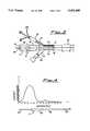
- FIG. 1shows schematically, in an enlarged scale, the distal end of the device according to this invention, which has to be introduced into a natural cavity of the human body;
- FIG. 1Ashows an enlarged schematic cross-section of the device according to this invention, taken along line A--A of FIG. 1;
- FIG. 2is a schematic of some structural details of a radiofrequency antenna shown in general within the device of FIG. 1;
- FIG. 2Ashows a schematic enlarged cross-section of the radiating antenna, taken along line A--A of FIG. 2;
- FIG. 3is a schematic of the proximal end of the device according to this invention, opposite to the distal end shown in FIG. 1;
- FIG. 4is a plot of the intensity of the radiation generated by the radiating antenna of FIG. 2, along the longitudinal axis thereof;
- FIG. 5shows schematically the distal end of the device of FIG. 1, as it is seen after having been introduced into a urinary bladder;
- FIG. 6shows schematically the structure at the distal end of the device shown in FIG. 1, when ready for introduction into the organ to be treated.
- the device according to this inventionhas a shape and consistency of a flexible catheter whose distal end, as it is shown in FIG. 1, encloses therewithin an antenna 1 surrounded by a flow of liquid 2 which is introduced into the bladder through an opening 3 and, after being freely circulated within said bladder, is again sucked into the catheter through an opening 4.
- Said opening 4is in communication with a second way or catheter side channel 5 housing the leads of several thermocouples, like for instance 6, 6', 6" adapted to be deflected outwards by inflating a balloon 7 in which a gaseous fluid or a liquid is made to flow through a third path or side channel 8 and through an end opening 9.
- the catheter opposite (proximal) end(FIG. 3) whose tip is shown in FIG. 1, has three diverging inlets corresponding to the three paths or channels 2, 5, 8 of said catheter.
- center inlet 10there is inserted with a pressure fit a plug 11 provided with a center through passage and with a side branch 13; in center passage 12 of plug 11 there is in turn pressure fitted a second plug 14 which is provided as well with a center opening 15.
- Shielded cable 16 supplying power to antenna 1runs through the center passages 12 and 15 of said two coaxially arranged plugs, while side branch 13 is provided as an inlet and an outlet of a conditioning fluid flowing along channel 2.
- Thermocouple power supply cables 6, 6', 6"are laid through side entrance 17 provided with a branch 18, and they run along side path or channel 5 having said conditioning liquid flowing in a reverse direction therethrough, said liquid entering and exiting in turn through said branch 18.
- the other side entrance 19is provided with a one-way valve 20 for introducing the fluid that, flowing along second side channel 8, is used to inflate balloon 7.
- a heat exchanger 31operated in a known fashion from outside, and used to cool or to heat said conditioning liquid flowing through central channel 2 and coming back through side channel 5, or viceversa.
- the useful radiating portion of linear dipole antenna 1comprises a terminal coil-shaped segment 21 of central conductor 22 which, immediately upstream from coil 21 is tightly surrounded, in sequence, by a first plastic inner sleeve 23, by a metal braiding 24, by a second intermediate plastic sleeve 25, by a metal cylinder 26 electrically connected with shield 24, and eventually by an outer plastic sleeve 27.
- thermocoupleslocated in a way suitable to detect the operating temperatures in predetermined positions of the antenna and of the power supply cable thereof.
- a first thermocouple 28may be located in the position of the stretch of catheter which will be located at the prostatic urethra when the catheter with its antenna are inserted within the bladder; a second thermocouple 29 slightly upstream from antenna 1, at the bladder neck, while a third thermocouple 30 is located close to central conductor 22, between metal cylinder 26 and end coil 21, after having been wrapped with one or more coils around shield 24 immediately upstream from intermediate sleeve 25 and metal cylinder 26, and a second time, with a larger number of coils, around the stretch of central lead 22 projecting out of metal cylinder 26 before winding up to form end coil 21, the stretch of thermocouple 30 power supply cable connecting said two points being inserted with intimate contact between intermediate sleeve 25 and metal cylinder 26.
- the end stretches of the power supply cables, immediately ahead of the thermocouples,are wrapped in a number of helical coils in order to increase the thermal capacity and the radiofrequency resistance of the ends which are designated to detect the temperature, while reducing to a minimum, or completely avoiding the dispersive thermal conduction along said cables.
- FIG. 1Awhich shows schematically a cross-section of the catheter according to this invention, taken in any position of the stretch going from heat exchanger 31 to intermediate sleeve 25, there is shown side channel 5 carrying the power supply cables of thermocouples 6, 6', 6" and side channel 8 for the flow of the fluid used to inflate balloon 7, both said channels 5 and 8 being managed within the thickness of the actual catheter whose inner bore 2 intended for the flow of the conditioning liquid carries, in a central position, shielded cable 16 comprised of central conductor 22, inner sleeve 23, shield 24 and outer sleeve 27, as well as inner thermocouples 28, 29 and 30 power supply cables (not shown).
- FIG. 2Ais a schematic cross-section of antenna 1, taken along line A--A of FIG. 2. The following are shown therein, starting from the center: conductor 22, inner sleeve 23, metal shield 24, an intermediate sleeve 25, a metal cylinder 26, and outer sleeve 27, as well as thermocouple 30 power supply conductor.
- FIG. 4is a diagram showing the radiation intensity starting from the coil-shaped end 21 of antenna 1 towards shielded power supply cable 22, 16. As it is shown, intensity is a maximum when passing from radiating coil 21 to the stretch protected by metal cylinder 26, and it tends to nil at the position of shielded cable 16.
- FIG. 5There is shown schematically in FIG. 5 the longitudinal section of the catheter provided with a radiating antenna according to this invention, once it has been introduced into the bladder, in an operative condition.
- the catheter, carrying the radiating antenna therewithinis introduced into bladder 32 through the urethra, in such a way that the rear end of protective metal cylinder 26 is located approximately at the bladder neck, in the transition area between prostata 33 and bladder 32, while simultaneously taking care that the catheter front end does not subject the bladder internal wall to any pressure.
- conditioning liquid 2preferably comprising a solution of a selective citotoxicity substance, which is accordingly forced to circulate through the bladder coming out from opening 3 and going back through opening 4, or viceversa, along side channel 5 which carries the power supply cables of thermocouples 6, 6', 6" therewithin.
- the liquid forced circulationprovided by the variable flowrate supply pump, suitably combined with an outer balancing and degassing chamber, allows the volume of liquid within the bladder to be balanced at will, in such a way as to compensate the pathological or physiological urine production, while thoroughly ejecting the gases generated or unwillingly introduced in circulation, out of the bladder, in order to prevent irradiation non-uniformities which would otherwise be caused by coexistance of anisotropic media.
- ballon 7is inflated by introducing a fluid, which may be a gas but it is preferably a liquid, along side channel 8 and through the end opening 9 thereof; ballon 7 inflated as mentioned above, pushes then against outer thermocouples 6, 6', 6" power supply cables thereby moving said thermocouples into tangential engagement against bladder wall 32 in different positions, in order to detect the temperatures prevailing therein as caused by irradiation generated by antenna 1.
- a fluidwhich may be a gas but it is preferably a liquid, along side channel 8 and through the end opening 9 thereof; ballon 7 inflated as mentioned above, pushes then against outer thermocouples 6, 6', 6" power supply cables thereby moving said thermocouples into tangential engagement against bladder wall 32 in different positions, in order to detect the temperatures prevailing therein as caused by irradiation generated by antenna 1.
- the possibility of changing the location and the number of the outer thermocouplesenables the thermocouples to be positioned at will, on the bladder wall, or in any case of the body organ to
- antenna 1The dimensions of antenna 1 are such that it may be freely positioned along the catheter while being obviously wholly contained within the human bladder to be treated, but in the meantime they must be suitable to generate a therapeutically active radiation, in order to reach the temperatures considered lethal for the cancer cells. Since the physical length of an antenna is related to the virtual electrical length thereof through an equation involving the impedence of said antenna, as well as the impedence deriving from the environment irradiated by the antenna, the antenna electrical length comes out to be inversely proportional to the irradiated medium conductivity. Accordingly, since the conductivity of an aqueous solution is for instance many times higher than the conductivity of air, when operating in an aqueous environment it is possible to use an antenna which is physically quite shorter than the length needed if it were necessary to operate in air.
- the dipole according to this inventioncorresponds to a dipole of the quarter wave type and in the aqueous environment comprising the solution filled bladder, it makes it possible to operate at frequencies in the range of 900-1000 MHz; in particular, a frequency of 915 MHz has been chosen since very different frequencies would result in penetration, intensity, and other effects not always exactly predictable and controllable in the body tissues, since in general high frequencies have a low penetration power and therefore they do not provide the desired local heating, while lower frequencies, having a higher penetration power, may get deeper tissues involved and damaged.
- the supply cable endstretches close to the thermocouples are wound into an helical shape whereby the temperature measured in the various sensing points is a reliable data, unaffected by said influences.
- the above structure constructionprevents measuring errors due to conduction, it provides a reliable temperature indication, for instance exactly in the area of the dipole power supply position in the case of thermocouple 30, and it reduces in an extremely effective manner the thermocouple self-heating process due to radiofrequencies, also when there is an extremely high concentration of energy, whereby said structures are almost unaffected by the disturbances in the radio-frequency field.
- the energy losses due for instance to self-heating of the antenna power supply cableare particularly high, for instance in the range of 20-40%. Since this undesirable self-heating, due to the Joule effect, might cause excessive heating of the urethral walls, and accordingly a discomfort for the patient subjected to treatment, or even damages to the tissues, the antenna cable, and the antenna itself are continuously cooled, while in operation, by using the conditioning liquid flow directed to the bladder and then withdrawn again therefrom, whereby a simultaneous control action is obtained, for controlling the temperature prevailing both in the liquid within the bladder and along the urethra. Temperature control is effected by variations of the conditioning liquid supply flow and of the cooling source temperature. In such a way it is possible both to increase the temperature and to withdraw heat.
- thermocouples 6, 6', 6"In order to enable outer thermocouples 6, 6', 6" for detecting the bladder wall temperature to be safely deflected outwards when ballonon 7 is inflated, the power supply cables thereof are reinforced along their whole length by inserting within the protecting sheath thereof a thin stainless steel wire providing them with the required rigidity and flexibility. The presence of said reinforcing wire provides as well he thermocouple power supply cables with the mechanical strength necessary to bear the compressive and tensile stresses caused when the cables are inserted within side channel 5, and when thermocouples 6, 6', 6" are laid in the desired locations.
- thermocouples 6, 6', 6" projecting upstream of balloon 7 through opening 4are temporarily locked by inserting them, downstream of balloon 7, in one or more notches provided, as the case may be, in suitable positions according to the different body organ or the particular patient to be treated, close to the catheter end, as it is shown in FIG. 6.
- balloon 7When balloon 7 is inflated it causes the thermocouple ends to come out from the notches and then to deflect outwards until the thermocouple tips come into engagement with the bladder wall.
- thermocouples 6, 6', 6"causes the ends of the respective power supply cables comprising the actual thermocouple, to tangentially engage the bladder wall, whereby no excessive concentrated pressures are generated.
- the tangential position taken by the thermocouple tips when contacting the bladder wallmakes it possible to measure the actual temperature of the wall position considered in that at the boundary between said wall and the liquid filling the bladder there is a thin liquid layer substantially stationary, which is not affected by the liquid circulation within the bladder, since it clings to the tissue because of a physical attraction, while the coil shape of the cable terminal stretches increases the thermal capacity of the thermocouple whose diameter, inclusive of the coils, is less than 0,7 mm whereby the thermocouple is completely submerged within the liquid stationary layer having a thickness of approximately 1 mm.
- thermocouplesAfter the thermocouples have been deflected outwards within the bladder, it is still possible to modify their location by performing pushing and/or pulling actions on the reinforced power supply cables, as mentioned above, and possibly by rotating the catheter containing them. Control of the temperature detected on the bladder walls and/or within the circulating liquid mass, is obtained by changing the flowrate of said liquid from few cubic centimeters per minute to several tens of cubic centimeters per minute.
- the circulated fluid circulating systemprevents permanence or formation and build-up of possible gas bubbles within the bladder or through the circuit, in that air or other gas bubbles having possibly formed or being already present, are entrained out by the continuous flow and exhausted to the outer environment in an appropriate position of the outer pumping circuit.
- the liquid circulation provided as abovepresents the antenna and the environment thereof from overheating, therefore from causing undesirable reactions within the circulating liquid.
Landscapes
- Health & Medical Sciences (AREA)
- Biomedical Technology (AREA)
- Engineering & Computer Science (AREA)
- Life Sciences & Earth Sciences (AREA)
- General Health & Medical Sciences (AREA)
- Animal Behavior & Ethology (AREA)
- Public Health (AREA)
- Veterinary Medicine (AREA)
- Nuclear Medicine, Radiotherapy & Molecular Imaging (AREA)
- Heart & Thoracic Surgery (AREA)
- Pathology (AREA)
- Radiology & Medical Imaging (AREA)
- Physics & Mathematics (AREA)
- Surgery (AREA)
- Otolaryngology (AREA)
- Electromagnetism (AREA)
- Medical Informatics (AREA)
- Molecular Biology (AREA)
- Vascular Medicine (AREA)
- Thermal Sciences (AREA)
- Thermotherapy And Cooling Therapy Devices (AREA)
- Radiation-Therapy Devices (AREA)
- Electrotherapy Devices (AREA)
- Physical Deposition Of Substances That Are Components Of Semiconductor Devices (AREA)
- Control And Other Processes For Unpacking Of Materials (AREA)
- Organic Low-Molecular-Weight Compounds And Preparation Thereof (AREA)
- Heat Treatment Of Articles (AREA)
- Media Introduction/Drainage Providing Device (AREA)
- Buildings Adapted To Withstand Abnormal External Influences (AREA)
- Meat, Egg Or Seafood Products (AREA)
Abstract
Description
Claims (1)
Priority Applications (2)
| Application Number | Priority Date | Filing Date | Title |
|---|---|---|---|
| US09/923,279USRE40559E1 (en) | 1991-11-11 | 1994-05-03 | Radiating device for hyperthermia |
| US08/889,825USRE37315E1 (en) | 1991-11-11 | 1997-07-08 | Radiating device for hyperthermia |
Applications Claiming Priority (3)
| Application Number | Priority Date | Filing Date | Title |
|---|---|---|---|
| ITMI91A2993 | 1991-11-11 | ||
| ITMI912993AIT1251997B (en) | 1991-11-11 | 1991-11-11 | RADIANT DEVICE FOR HYPERTHERMIA |
| PCT/IT1992/000142WO1993009724A1 (en) | 1991-11-11 | 1992-11-10 | A radiating device for hyperthermia |
Related Parent Applications (1)
| Application Number | Title | Priority Date | Filing Date |
|---|---|---|---|
| US08/889,825ContinuationUSRE37315E1 (en) | 1991-11-11 | 1997-07-08 | Radiating device for hyperthermia |
Related Child Applications (2)
| Application Number | Title | Priority Date | Filing Date |
|---|---|---|---|
| US09/923,279ReissueUSRE40559E1 (en) | 1991-11-11 | 1994-05-03 | Radiating device for hyperthermia |
| US08/889,825ReissueUSRE37315E1 (en) | 1991-11-11 | 1997-07-08 | Radiating device for hyperthermia |
Publications (1)
| Publication Number | Publication Date |
|---|---|
| US5431648Atrue US5431648A (en) | 1995-07-11 |
Family
ID=11361066
Family Applications (4)
| Application Number | Title | Priority Date | Filing Date |
|---|---|---|---|
| US08/232,190CeasedUS5431648A (en) | 1991-11-11 | 1992-11-10 | Radiating device for hyperthermia |
| US09/923,279Expired - LifetimeUSRE40559E1 (en) | 1991-11-11 | 1994-05-03 | Radiating device for hyperthermia |
| US08/889,825Expired - LifetimeUSRE37315E1 (en) | 1991-11-11 | 1997-07-08 | Radiating device for hyperthermia |
| US09/923,279GrantedUS20020077625A1 (en) | 1991-11-11 | 2001-08-06 | Radiating device for hyperthermia |
Family Applications After (3)
| Application Number | Title | Priority Date | Filing Date |
|---|---|---|---|
| US09/923,279Expired - LifetimeUSRE40559E1 (en) | 1991-11-11 | 1994-05-03 | Radiating device for hyperthermia |
| US08/889,825Expired - LifetimeUSRE37315E1 (en) | 1991-11-11 | 1997-07-08 | Radiating device for hyperthermia |
| US09/923,279GrantedUS20020077625A1 (en) | 1991-11-11 | 2001-08-06 | Radiating device for hyperthermia |
Country Status (13)
| Country | Link |
|---|---|
| US (4) | US5431648A (en) |
| EP (1) | EP0612228B1 (en) |
| JP (2) | JP3635086B2 (en) |
| KR (1) | KR100251010B1 (en) |
| AT (1) | ATE150632T1 (en) |
| CA (1) | CA2123137C (en) |
| DE (1) | DE69218619T2 (en) |
| DK (1) | DK0612228T3 (en) |
| ES (1) | ES2100369T3 (en) |
| GR (1) | GR3023121T3 (en) |
| HK (1) | HK1006800A1 (en) |
| IT (1) | IT1251997B (en) |
| WO (1) | WO1993009724A1 (en) |
Cited By (39)
| Publication number | Priority date | Publication date | Assignee | Title |
|---|---|---|---|---|
| US5618266A (en)* | 1994-03-31 | 1997-04-08 | Liprie; Samuel F. | Catheter for maneuvering radioactive source wire to site of treatment |
| US5735817A (en)* | 1995-05-19 | 1998-04-07 | Shantha; T. R. | Apparatus for transsphenoidal stimulation of the pituitary gland and adjoining brain structures |
| US5891134A (en)* | 1996-09-24 | 1999-04-06 | Goble; Colin | System and method for applying thermal energy to tissue |
| US5913854A (en)* | 1997-02-04 | 1999-06-22 | Medtronic, Inc. | Fluid cooled ablation catheter and method for making |
| EP0801938A3 (en)* | 1996-04-16 | 1999-08-25 | ARGOMED Ltd. | Thermal treatment apparatus |
| US5957917A (en)* | 1995-01-20 | 1999-09-28 | Miravant Systems, Inc. | Transluminal hyperthermia catheter and method for use |
| US6022342A (en)* | 1998-06-02 | 2000-02-08 | Mukherjee; Dipankar | Catheter introducer for antegrade and retrograde medical procedures |
| US6083148A (en)* | 1991-06-14 | 2000-07-04 | Proxima Therapeutics, Inc. | Tumor treatment |
| US6139570A (en)* | 1997-05-19 | 2000-10-31 | Gynelab Products, Inc. | Disposable bladder for intrauterine use |
| US6275738B1 (en)* | 1999-08-19 | 2001-08-14 | Kai Technologies, Inc. | Microwave devices for medical hyperthermia, thermotherapy and diagnosis |
| US6302878B1 (en)* | 1995-06-27 | 2001-10-16 | S.L.T. Japan Co., Ltd. | System for laser light irradiation to living body |
| US6322560B1 (en)* | 1996-12-24 | 2001-11-27 | Thermo-Med 2000 Kft | Catheter for radiofrequency ablation of tumors |
| USRE37704E1 (en) | 1990-03-22 | 2002-05-14 | Argomed Ltd. | Thermal treatment apparatus |
| US20030060762A1 (en)* | 2001-09-27 | 2003-03-27 | Galil Medical Ltd. | Cryoplasty apparatus and method |
| US20030229384A1 (en)* | 2000-06-20 | 2003-12-11 | Celsion Corporation | Method and apparatus for treatment of tissue adjacent a bodily conduit with a compression balloon |
| US6706040B2 (en)* | 2001-11-23 | 2004-03-16 | Medlennium Technologies, Inc. | Invasive therapeutic probe |
| US20040064152A1 (en)* | 2001-09-27 | 2004-04-01 | Roni Zvuloni | Device, system, and method for cryosurgical treatment of cardiac arrhythmia |
| US20040133068A1 (en)* | 2000-10-23 | 2004-07-08 | Gary Miller | Apparatus and method for the measurement of the resistance of the urethral sphincter |
| US20040243199A1 (en)* | 2001-09-18 | 2004-12-02 | Celsion Corporation | Device and method for treatment of tissue adjacent a bodily conduit by thermocompression |
| US6849063B1 (en) | 1994-03-11 | 2005-02-01 | Wit Ip Corporation | Thermal treatment apparatus |
| GB2416307A (en)* | 2004-07-16 | 2006-01-25 | Microsulis Ltd | Microwave applicator head with null forming conductors allowing for sensor placement |
| US20060135953A1 (en)* | 2004-12-22 | 2006-06-22 | Wlodzimierz Kania | Tissue ablation system including guidewire with sensing element |
| US20070055328A1 (en)* | 2005-09-02 | 2007-03-08 | Mayse Martin L | Device and method for esophageal cooling |
| US20070142694A1 (en)* | 2005-12-16 | 2007-06-21 | North American Scientific | Brachytherapy apparatus |
| US20070270627A1 (en)* | 2005-12-16 | 2007-11-22 | North American Scientific | Brachytherapy apparatus for asymmetrical body cavities |
| US20070288075A1 (en)* | 2006-05-24 | 2007-12-13 | Rush University Medical Center | High temperature thermal therapy of breast cancer |
| US20080146862A1 (en)* | 2006-04-21 | 2008-06-19 | North American Scientific, Inc. | Brachytherapy Device Having Seed Tubes With Individually-Settable Tissue Spacings |
| US20100049186A1 (en)* | 1997-08-13 | 2010-02-25 | Ams Research Corporation | Noninvasive devices, methods, and systems for shrinking of tissues |
| US20110034976A1 (en)* | 2002-02-15 | 2011-02-10 | John Mon | Drug delivery |
| US20120265199A1 (en)* | 2011-04-12 | 2012-10-18 | Thermedical, Inc. | Methods and devices for use of degassed fluids with fluid enhanced ablation devices |
| US8968284B2 (en) | 2000-10-02 | 2015-03-03 | Verathon Inc. | Apparatus and methods for treating female urinary incontinence |
| US9033972B2 (en) | 2013-03-15 | 2015-05-19 | Thermedical, Inc. | Methods and devices for fluid enhanced microwave ablation therapy |
| US9089315B1 (en)* | 2009-09-02 | 2015-07-28 | The Regents Of The University Of California | Methods and devices for adjunctive local hypothermia |
| US9610396B2 (en) | 2013-03-15 | 2017-04-04 | Thermedical, Inc. | Systems and methods for visualizing fluid enhanced ablation therapy |
| US9743984B1 (en) | 2016-08-11 | 2017-08-29 | Thermedical, Inc. | Devices and methods for delivering fluid to tissue during ablation therapy |
| CN107224671A (en)* | 2017-06-09 | 2017-10-03 | 深圳市美的连医疗电子股份有限公司 | Cavity therapeutic equipment |
| US10022176B2 (en) | 2012-08-15 | 2018-07-17 | Thermedical, Inc. | Low profile fluid enhanced ablation therapy devices and methods |
| US11083871B2 (en) | 2018-05-03 | 2021-08-10 | Thermedical, Inc. | Selectively deployable catheter ablation devices |
| US11918277B2 (en) | 2018-07-16 | 2024-03-05 | Thermedical, Inc. | Inferred maximum temperature monitoring for irrigated ablation therapy |
Families Citing this family (33)
| Publication number | Priority date | Publication date | Assignee | Title |
|---|---|---|---|---|
| US5931774A (en)* | 1991-06-14 | 1999-08-03 | Proxima Therapeutics, Inc. | Inflatable devices for tumor treatment |
| US5913813A (en) | 1997-07-24 | 1999-06-22 | Proxima Therapeutics, Inc. | Double-wall balloon catheter for treatment of proliferative tissue |
| SE518946C2 (en)* | 1997-07-28 | 2002-12-10 | Prostalund Operations Ab | Device for combined heat treatment of body tissue |
| GB9809536D0 (en)* | 1998-05-06 | 1998-07-01 | Microsulis Plc | Sensor positioning |
| SE521014C2 (en) | 1999-02-04 | 2003-09-23 | Prostalund Operations Ab | Apparatus for heat treatment of prostate |
| SE521275C2 (en) | 1999-05-07 | 2003-10-14 | Prostalund Operations Ab | Device for heat treatment of body tissue |
| US7160296B2 (en)* | 2001-05-10 | 2007-01-09 | Rita Medical Systems, Inc. | Tissue ablation apparatus and method |
| US6868290B2 (en) | 2001-11-05 | 2005-03-15 | Prostalund Operations Ab | Thermotherapy catheter and method of prostate thermotherapy with improved guide and heat confinement |
| US6755849B1 (en)* | 2002-03-28 | 2004-06-29 | Board Of Regents, The University Of Texas System | Method for delivering energy to tissue and apparatus |
| US6695760B1 (en) | 2002-10-11 | 2004-02-24 | Proxima Therapeutics | Treatment of spinal metastases |
| US6749555B1 (en) | 2003-02-13 | 2004-06-15 | Proxima Therapeutics, Inc. | System and method for the treatment of spinal metastases |
| US7018398B2 (en)* | 2003-03-18 | 2006-03-28 | Elmedical Ltd. | System and method for treating urinary tract disorders |
| US7524274B2 (en) | 2003-11-07 | 2009-04-28 | Cytyc Corporation | Tissue positioning systems and methods for use with radiation therapy |
| US7494457B2 (en) | 2003-11-07 | 2009-02-24 | Cytyc Corporation | Brachytherapy apparatus and method for treating a target tissue through an external surface of the tissue |
| US7354391B2 (en) | 2003-11-07 | 2008-04-08 | Cytyc Corporation | Implantable radiotherapy/brachytherapy radiation detecting apparatus and methods |
| US7524275B2 (en) | 2003-11-14 | 2009-04-28 | Cytyc Corporation | Drug eluting brachytherapy methods and apparatus |
| AU2004293064B2 (en) | 2003-11-20 | 2011-08-18 | Cytyc Corporation | Brachytherapy method and applicator for treatment of metastatic lesions in a load bearing region |
| US7753907B2 (en)* | 2004-10-29 | 2010-07-13 | Boston Scientific Scimed, Inc. | Medical device systems and methods |
| US7662082B2 (en) | 2004-11-05 | 2010-02-16 | Theragenics Corporation | Expandable brachytherapy device |
| US7465268B2 (en) | 2005-11-18 | 2008-12-16 | Senorx, Inc. | Methods for asymmetrical irradiation of a body cavity |
| US8328711B2 (en) | 2007-12-18 | 2012-12-11 | Cytyc Corporation | Selectable multi-lumen brachytherapy devices and methods |
| US9050069B2 (en) | 2008-05-16 | 2015-06-09 | Medtronic Cryocath Lp | Thermocouple-controlled catheter cooling system |
| US9248311B2 (en) | 2009-02-11 | 2016-02-02 | Hologic, Inc. | System and method for modifying a flexibility of a brachythereapy catheter |
| US9579524B2 (en) | 2009-02-11 | 2017-02-28 | Hologic, Inc. | Flexible multi-lumen brachytherapy device |
| US8382650B2 (en) | 2009-05-11 | 2013-02-26 | Cytyc Corporation | Catheter marking for multi-lumen catheter identification |
| US10207126B2 (en) | 2009-05-11 | 2019-02-19 | Cytyc Corporation | Lumen visualization and identification system for multi-lumen balloon catheter |
| US9352172B2 (en) | 2010-09-30 | 2016-05-31 | Hologic, Inc. | Using a guide member to facilitate brachytherapy device swap |
| US10342992B2 (en) | 2011-01-06 | 2019-07-09 | Hologic, Inc. | Orienting a brachytherapy applicator |
| WO2016100901A1 (en)* | 2014-12-19 | 2016-06-23 | Memorial Sloan-Kettering Cancer Center | Urinary catheter for facilitating control of bladder content volume and methods for use thereof |
| CN104434015A (en)* | 2014-12-31 | 2015-03-25 | 杨幼林 | Multifunctional outer cannula device for colonoscope |
| EP4186450B1 (en) | 2016-12-09 | 2025-01-22 | St. Jude Medical, Cardiology Division, Inc. | Pulmonary vein isolation balloon catheter |
| AU2019207630B2 (en)* | 2018-01-10 | 2021-08-12 | Adagio Medical, Inc. | Device for monitoring temperatures within and adjacent to body lumens |
| CN119816273A (en) | 2022-04-29 | 2025-04-11 | 阿尔克泰斯医疗公司 | Devices and methods for cooling and/or heating an organ |
Citations (15)
| Publication number | Priority date | Publication date | Assignee | Title |
|---|---|---|---|---|
| US4154246A (en)* | 1977-07-25 | 1979-05-15 | Leveen Harry H | Field intensification in radio frequency thermotherapy |
| GB2045620A (en)* | 1979-03-23 | 1980-11-05 | Rca Corp | Coaxial applicator for hyperthermic treatment of the body |
| US4375220A (en)* | 1980-05-09 | 1983-03-01 | Matvias Fredrick M | Microwave applicator with cooling mechanism for intracavitary treatment of cancer |
| WO1989011311A1 (en)* | 1988-05-18 | 1989-11-30 | Kasevich Associates, Inc. | Microwave balloon angioplasty |
| WO1990003152A1 (en)* | 1988-09-24 | 1990-04-05 | John Considine | Electro-surgical apparatus for removing tumours from hollow organs of the body |
| US4924863A (en)* | 1988-05-04 | 1990-05-15 | Mmtc, Inc. | Angioplastic method for removing plaque from a vas |
| EP0370890A1 (en)* | 1988-11-21 | 1990-05-30 | Technomed Medical Systems | Apparatus for the surgical treatment of tissues by hyperthermia, preferably the prostate, equipped with heat protection means preferably comprising means forming radioreflecting screen |
| US4967765A (en)* | 1988-07-28 | 1990-11-06 | Bsd Medical Corporation | Urethral inserted applicator for prostate hyperthermia |
| US5000734A (en)* | 1988-02-01 | 1991-03-19 | Georges Boussignac | Probe intended to be introduced within a living body |
| US5007437A (en)* | 1989-06-16 | 1991-04-16 | Mmtc, Inc. | Catheters for treating prostate disease |
| US5090958A (en)* | 1988-11-23 | 1992-02-25 | Harvinder Sahota | Balloon catheters |
| US5103804A (en)* | 1990-07-03 | 1992-04-14 | Boston Scientific Corporation | Expandable tip hemostatic probes and the like |
| US5168880A (en)* | 1986-07-17 | 1992-12-08 | Olympus Optical Co., Ltd. | Apparatus for dielectric-heating living body by high-frequency current and apparatus therefor |
| FR2679456A1 (en)* | 1991-07-26 | 1993-01-29 | Technomed Int Sa | Apparatus for in situ thermotherapy treatment of the mucous membrane of the uterine cavity |
| US5191883A (en)* | 1988-10-28 | 1993-03-09 | Prutech Research And Development Partnership Ii | Device for heating tissue in a patient's body |
Family Cites Families (30)
| Publication number | Priority date | Publication date | Assignee | Title |
|---|---|---|---|---|
| DE2848636A1 (en) | 1978-11-09 | 1980-05-22 | Mark | Cavity scavenging device for cancer hyperthermia treatment - has inlet and outlet channels coupled to external scavenging liq. circuit contg. pump, thermostat and heater |
| JPS5957650A (en) | 1982-09-27 | 1984-04-03 | 呉羽化学工業株式会社 | Probe for heating body cavity |
| CA1244889A (en) | 1983-01-24 | 1988-11-15 | Kureha Chemical Ind Co Ltd | Device for hyperthermia |
| JPS60119962A (en) | 1983-12-01 | 1985-06-27 | オリンパス光学工業株式会社 | Electrode apparatus for body cavity |
| EP0321614B1 (en) | 1987-12-21 | 1993-03-31 | Reynaldo Calderon | Systems for retrograde perfusion in the body for curing it of a disease or immune deficiency |
| US4776334A (en) | 1985-03-22 | 1988-10-11 | Stanford University | Catheter for treatment of tumors |
| JPS6294152A (en) | 1985-10-18 | 1987-04-30 | オリンパス光学工業株式会社 | Medical heat treatment apparatus |
| JPS62211056A (en)* | 1986-03-12 | 1987-09-17 | オリンパス光学工業株式会社 | Tissue incision apparatus |
| IL78756A0 (en) | 1986-05-12 | 1986-08-31 | Biodan Medical Systems Ltd | Catheter and probe |
| DE3620123A1 (en) | 1986-06-14 | 1987-12-17 | Strahlen Umweltforsch Gmbh | MEASURING AND RADIATION DEVICE FOR CAVITIES |
| US5220927A (en) | 1988-07-28 | 1993-06-22 | Bsd Medical Corporation | Urethral inserted applicator for prostate hyperthermia |
| US5249585A (en) | 1988-07-28 | 1993-10-05 | Bsd Medical Corporation | Urethral inserted applicator for prostate hyperthermia |
| US5344435A (en) | 1988-07-28 | 1994-09-06 | Bsd Medical Corporation | Urethral inserted applicator prostate hyperthermia |
| JPH0265941U (en) | 1988-11-07 | 1990-05-17 | ||
| US5129396A (en)* | 1988-11-10 | 1992-07-14 | Arye Rosen | Microwave aided balloon angioplasty with lumen measurement |
| US4979948A (en) | 1989-04-13 | 1990-12-25 | Purdue Research Foundation | Method and apparatus for thermally destroying a layer of an organ |
| US5114423A (en) | 1989-05-15 | 1992-05-19 | Advanced Cardiovascular Systems, Inc. | Dilatation catheter assembly with heated balloon |
| US5084044A (en)* | 1989-07-14 | 1992-01-28 | Ciron Corporation | Apparatus for endometrial ablation and method of using same |
| IL93842A (en) | 1990-03-22 | 1995-10-31 | Argomed Ltd | Apparatus for localized thermal treatment of mammals |
| US5190540A (en)* | 1990-06-08 | 1993-03-02 | Cardiovascular & Interventional Research Consultants, Inc. | Thermal balloon angioplasty |
| US5195965A (en) | 1991-03-07 | 1993-03-23 | Shantha Totada R | Method and apparatus for localized treatment of human viral infections and cancers |
| US5301687A (en) | 1991-06-06 | 1994-04-12 | Trustees Of Dartmouth College | Microwave applicator for transurethral hyperthermia |
| US5330518A (en)* | 1992-03-06 | 1994-07-19 | Urologix, Inc. | Method for treating interstitial tissue associated with microwave thermal therapy |
| US5292320A (en)* | 1992-07-06 | 1994-03-08 | Ceramoptec, Inc. | Radial medical laser delivery device |
| US5348554A (en) | 1992-12-01 | 1994-09-20 | Cardiac Pathways Corporation | Catheter for RF ablation with cooled electrode |
| US5336222A (en)* | 1993-03-29 | 1994-08-09 | Boston Scientific Corporation | Integrated catheter for diverse in situ tissue therapy |
| US5403311A (en)* | 1993-03-29 | 1995-04-04 | Boston Scientific Corporation | Electro-coagulation and ablation and other electrotherapeutic treatments of body tissue |
| US5472441A (en) | 1993-11-08 | 1995-12-05 | Zomed International | Device for treating cancer and non-malignant tumors and methods |
| US5599346A (en) | 1993-11-08 | 1997-02-04 | Zomed International, Inc. | RF treatment system |
| US5505730A (en)* | 1994-06-24 | 1996-04-09 | Stuart D. Edwards | Thin layer ablation apparatus |
- 1991
- 1991-11-11ITITMI912993Apatent/IT1251997B/enactiveIP Right Grant
- 1992
- 1992-11-10CACA002123137Apatent/CA2123137C/ennot_activeExpired - Lifetime
- 1992-11-10ATAT92924853Tpatent/ATE150632T1/ennot_activeIP Right Cessation
- 1992-11-10ESES92924853Tpatent/ES2100369T3/ennot_activeExpired - Lifetime
- 1992-11-10EPEP92924853Apatent/EP0612228B1/ennot_activeExpired - Lifetime
- 1992-11-10JPJP50913393Apatent/JP3635086B2/ennot_activeExpired - Fee Related
- 1992-11-10KRKR1019940701580Apatent/KR100251010B1/ennot_activeExpired - Fee Related
- 1992-11-10WOPCT/IT1992/000142patent/WO1993009724A1/enactiveIP Right Grant
- 1992-11-10DKDK92924853.2Tpatent/DK0612228T3/enactive
- 1992-11-10DEDE69218619Tpatent/DE69218619T2/ennot_activeExpired - Lifetime
- 1992-11-10USUS08/232,190patent/US5431648A/ennot_activeCeased
- 1994
- 1994-05-03USUS09/923,279patent/USRE40559E1/ennot_activeExpired - Lifetime
- 1997
- 1997-04-14GRGR960403505Tpatent/GR3023121T3/enunknown
- 1997-07-08USUS08/889,825patent/USRE37315E1/ennot_activeExpired - Lifetime
- 1998
- 1998-05-21HKHK98104413Apatent/HK1006800A1/ennot_activeIP Right Cessation
- 2001
- 2001-08-06USUS09/923,279patent/US20020077625A1/enactiveGranted
- 2004
- 2004-04-21JPJP2004126170Apatent/JP2004255206A/ennot_activeWithdrawn
Patent Citations (15)
| Publication number | Priority date | Publication date | Assignee | Title |
|---|---|---|---|---|
| US4154246A (en)* | 1977-07-25 | 1979-05-15 | Leveen Harry H | Field intensification in radio frequency thermotherapy |
| GB2045620A (en)* | 1979-03-23 | 1980-11-05 | Rca Corp | Coaxial applicator for hyperthermic treatment of the body |
| US4375220A (en)* | 1980-05-09 | 1983-03-01 | Matvias Fredrick M | Microwave applicator with cooling mechanism for intracavitary treatment of cancer |
| US5168880A (en)* | 1986-07-17 | 1992-12-08 | Olympus Optical Co., Ltd. | Apparatus for dielectric-heating living body by high-frequency current and apparatus therefor |
| US5000734A (en)* | 1988-02-01 | 1991-03-19 | Georges Boussignac | Probe intended to be introduced within a living body |
| US4924863A (en)* | 1988-05-04 | 1990-05-15 | Mmtc, Inc. | Angioplastic method for removing plaque from a vas |
| WO1989011311A1 (en)* | 1988-05-18 | 1989-11-30 | Kasevich Associates, Inc. | Microwave balloon angioplasty |
| US4967765A (en)* | 1988-07-28 | 1990-11-06 | Bsd Medical Corporation | Urethral inserted applicator for prostate hyperthermia |
| WO1990003152A1 (en)* | 1988-09-24 | 1990-04-05 | John Considine | Electro-surgical apparatus for removing tumours from hollow organs of the body |
| US5191883A (en)* | 1988-10-28 | 1993-03-09 | Prutech Research And Development Partnership Ii | Device for heating tissue in a patient's body |
| EP0370890A1 (en)* | 1988-11-21 | 1990-05-30 | Technomed Medical Systems | Apparatus for the surgical treatment of tissues by hyperthermia, preferably the prostate, equipped with heat protection means preferably comprising means forming radioreflecting screen |
| US5090958A (en)* | 1988-11-23 | 1992-02-25 | Harvinder Sahota | Balloon catheters |
| US5007437A (en)* | 1989-06-16 | 1991-04-16 | Mmtc, Inc. | Catheters for treating prostate disease |
| US5103804A (en)* | 1990-07-03 | 1992-04-14 | Boston Scientific Corporation | Expandable tip hemostatic probes and the like |
| FR2679456A1 (en)* | 1991-07-26 | 1993-01-29 | Technomed Int Sa | Apparatus for in situ thermotherapy treatment of the mucous membrane of the uterine cavity |
Cited By (86)
| Publication number | Priority date | Publication date | Assignee | Title |
|---|---|---|---|---|
| USRE37704E1 (en) | 1990-03-22 | 2002-05-14 | Argomed Ltd. | Thermal treatment apparatus |
| US6083148A (en)* | 1991-06-14 | 2000-07-04 | Proxima Therapeutics, Inc. | Tumor treatment |
| US6849063B1 (en) | 1994-03-11 | 2005-02-01 | Wit Ip Corporation | Thermal treatment apparatus |
| US5618266A (en)* | 1994-03-31 | 1997-04-08 | Liprie; Samuel F. | Catheter for maneuvering radioactive source wire to site of treatment |
| US5957917A (en)* | 1995-01-20 | 1999-09-28 | Miravant Systems, Inc. | Transluminal hyperthermia catheter and method for use |
| US5735817A (en)* | 1995-05-19 | 1998-04-07 | Shantha; T. R. | Apparatus for transsphenoidal stimulation of the pituitary gland and adjoining brain structures |
| US5792100A (en)* | 1995-05-19 | 1998-08-11 | Shantha; T. R. | Treatment method for transsphenoidal stimulation of the pituitary gland and of nerve structures |
| US6302878B1 (en)* | 1995-06-27 | 2001-10-16 | S.L.T. Japan Co., Ltd. | System for laser light irradiation to living body |
| EP0801938A3 (en)* | 1996-04-16 | 1999-08-25 | ARGOMED Ltd. | Thermal treatment apparatus |
| US5891134A (en)* | 1996-09-24 | 1999-04-06 | Goble; Colin | System and method for applying thermal energy to tissue |
| US6322560B1 (en)* | 1996-12-24 | 2001-11-27 | Thermo-Med 2000 Kft | Catheter for radiofrequency ablation of tumors |
| US5913854A (en)* | 1997-02-04 | 1999-06-22 | Medtronic, Inc. | Fluid cooled ablation catheter and method for making |
| US6139570A (en)* | 1997-05-19 | 2000-10-31 | Gynelab Products, Inc. | Disposable bladder for intrauterine use |
| US20100049186A1 (en)* | 1997-08-13 | 2010-02-25 | Ams Research Corporation | Noninvasive devices, methods, and systems for shrinking of tissues |
| US9023031B2 (en)* | 1997-08-13 | 2015-05-05 | Verathon Inc. | Noninvasive devices, methods, and systems for modifying tissues |
| US6022342A (en)* | 1998-06-02 | 2000-02-08 | Mukherjee; Dipankar | Catheter introducer for antegrade and retrograde medical procedures |
| US6275738B1 (en)* | 1999-08-19 | 2001-08-14 | Kai Technologies, Inc. | Microwave devices for medical hyperthermia, thermotherapy and diagnosis |
| US8221414B2 (en) | 2000-06-20 | 2012-07-17 | Boston Scientific Corporation | Catheter |
| US7837720B2 (en) | 2000-06-20 | 2010-11-23 | Boston Scientific Corporation | Apparatus for treatment of tissue adjacent a bodily conduit with a gene or drug-coated compression balloon |
| US20110028886A1 (en)* | 2000-06-20 | 2011-02-03 | Boston Scientific Corporation | Catheter |
| US20030229384A1 (en)* | 2000-06-20 | 2003-12-11 | Celsion Corporation | Method and apparatus for treatment of tissue adjacent a bodily conduit with a compression balloon |
| US8968284B2 (en) | 2000-10-02 | 2015-03-03 | Verathon Inc. | Apparatus and methods for treating female urinary incontinence |
| US20040133068A1 (en)* | 2000-10-23 | 2004-07-08 | Gary Miller | Apparatus and method for the measurement of the resistance of the urethral sphincter |
| US6969347B2 (en)* | 2000-10-23 | 2005-11-29 | Ethicon, Inc. | Apparatus and method for the measurement of the resistance of the urethral sphincter |
| US20040243199A1 (en)* | 2001-09-18 | 2004-12-02 | Celsion Corporation | Device and method for treatment of tissue adjacent a bodily conduit by thermocompression |
| US6958075B2 (en)* | 2001-09-18 | 2005-10-25 | Celsion Corporation | Device and method for treatment of tissue adjacent a bodily conduit by thermocompression |
| US8221413B2 (en) | 2001-09-18 | 2012-07-17 | Boston Scientific Corporation | Device and method for treatment of tissue adjacent a bodily conduit by thermocompression |
| US7811313B2 (en) | 2001-09-18 | 2010-10-12 | Boston Scientific Corporation | Device for treatment of tissue adjacent a bodily conduit by thermocompression |
| US20100298913A1 (en)* | 2001-09-18 | 2010-11-25 | Boston Scientific Corporation | Device and method for treatment of tissue adjacent a bodily conduit by thermocompression |
| US20050240117A1 (en)* | 2001-09-27 | 2005-10-27 | Galil Medical Ltd. | Thermal sensing device for thermal mapping of a body conduit |
| US6875209B2 (en)* | 2001-09-27 | 2005-04-05 | Galil Medical Ltd. | Cryoplasty apparatus and method |
| US20040260328A1 (en)* | 2001-09-27 | 2004-12-23 | Roni Zvuloni | Cryoplasty apparatus and method |
| US20040064152A1 (en)* | 2001-09-27 | 2004-04-01 | Roni Zvuloni | Device, system, and method for cryosurgical treatment of cardiac arrhythmia |
| US20030060762A1 (en)* | 2001-09-27 | 2003-03-27 | Galil Medical Ltd. | Cryoplasty apparatus and method |
| US6706040B2 (en)* | 2001-11-23 | 2004-03-16 | Medlennium Technologies, Inc. | Invasive therapeutic probe |
| US20110034976A1 (en)* | 2002-02-15 | 2011-02-10 | John Mon | Drug delivery |
| US8374702B2 (en) | 2002-02-15 | 2013-02-12 | Medifocus, Inc. | Drug delivery |
| US8224455B2 (en) | 2002-02-15 | 2012-07-17 | Boston Scientific Corporation | Drug delivery |
| GB2416307A (en)* | 2004-07-16 | 2006-01-25 | Microsulis Ltd | Microwave applicator head with null forming conductors allowing for sensor placement |
| US20080312643A1 (en)* | 2004-12-22 | 2008-12-18 | Cryocath Technologies Inc. | Tissue ablation system including guidewire with sensing element |
| US20080312642A1 (en)* | 2004-12-22 | 2008-12-18 | Cryocath Technologies Inc. | Tissue ablation system including guidewire with sensing element |
| US20060135953A1 (en)* | 2004-12-22 | 2006-06-22 | Wlodzimierz Kania | Tissue ablation system including guidewire with sensing element |
| US20070055328A1 (en)* | 2005-09-02 | 2007-03-08 | Mayse Martin L | Device and method for esophageal cooling |
| US20090326314A1 (en)* | 2005-12-16 | 2009-12-31 | Cutrer L Michael | Brachytherapy apparatus for asymmetrical body cavities |
| US20070142694A1 (en)* | 2005-12-16 | 2007-06-21 | North American Scientific | Brachytherapy apparatus |
| US8137256B2 (en) | 2005-12-16 | 2012-03-20 | Portola Medical, Inc. | Brachytherapy apparatus |
| US20070270627A1 (en)* | 2005-12-16 | 2007-11-22 | North American Scientific | Brachytherapy apparatus for asymmetrical body cavities |
| US8226539B2 (en) | 2005-12-16 | 2012-07-24 | Portola Medical, Inc. | Brachytherapy apparatus for asymmetrical body cavities |
| US7862497B2 (en) | 2006-04-21 | 2011-01-04 | Portola Medical, Inc. | Brachytherapy device having seed tubes with individually-settable tissue spacings |
| US20080146862A1 (en)* | 2006-04-21 | 2008-06-19 | North American Scientific, Inc. | Brachytherapy Device Having Seed Tubes With Individually-Settable Tissue Spacings |
| US20070288075A1 (en)* | 2006-05-24 | 2007-12-13 | Rush University Medical Center | High temperature thermal therapy of breast cancer |
| US8486127B2 (en)* | 2006-05-24 | 2013-07-16 | Kambiz Dowlatshahi | High temperature thermal therapy of breast cancer |
| US9089315B1 (en)* | 2009-09-02 | 2015-07-28 | The Regents Of The University Of California | Methods and devices for adjunctive local hypothermia |
| US20150351823A1 (en)* | 2011-04-12 | 2015-12-10 | Thermedical, Inc. | Methods and devices for use of degassed fluids with fluid enhanced ablation devices |
| US11950829B2 (en)* | 2011-04-12 | 2024-04-09 | Thermedical, Inc. | Methods and devices for use of degassed fluids with fluid enhanced ablation devices |
| US8945121B2 (en)* | 2011-04-12 | 2015-02-03 | Thermedical, Inc. | Methods and devices for use of degassed fluids with fluid enhanced ablation devices |
| US20250082389A1 (en)* | 2011-04-12 | 2025-03-13 | Thermedical, Inc. | Methods and devices for use of degassed fluids with fluid enhanced ablation devices |
| US8702697B2 (en) | 2011-04-12 | 2014-04-22 | Thermedical, Inc. | Devices and methods for shaping therapy in fluid enhanced ablation |
| US9138287B2 (en) | 2011-04-12 | 2015-09-22 | Thermedical, Inc. | Methods and devices for heating fluid in fluid enhanced ablation therapy |
| US9138288B2 (en)* | 2011-04-12 | 2015-09-22 | Thermedical, Inc. | Methods and devices for use of degassed fluids with fluid enhanced ablation devices |
| US20120265199A1 (en)* | 2011-04-12 | 2012-10-18 | Thermedical, Inc. | Methods and devices for use of degassed fluids with fluid enhanced ablation devices |
| US9445861B2 (en) | 2011-04-12 | 2016-09-20 | Thermedical, Inc. | Methods and devices for controlling ablation therapy |
| US20150066025A1 (en)* | 2011-04-12 | 2015-03-05 | Thermedical, Inc. | Methods and devices for use of degassed fluids with fluid enhanced ablation devices |
| US9730748B2 (en) | 2011-04-12 | 2017-08-15 | Thermedical, Inc. | Devices and methods for shaping therapy in fluid enhanced ablation |
| US11135000B2 (en) | 2011-04-12 | 2021-10-05 | Thermedical, Inc. | Methods and devices for use of degassed fluids with fluid enhanced ablation devices |
| US11871979B2 (en) | 2011-04-12 | 2024-01-16 | Thermedical, Inc. | Methods and devices for controlling ablation therapy |
| CN107334529A (en)* | 2011-04-12 | 2017-11-10 | 热医学公司 | The method and apparatus that deaeration fluid is used for the enhanced ablating device of convection body |
| US9877768B2 (en) | 2011-04-12 | 2018-01-30 | Thermedical, Inc. | Methods and devices for heating fluid in fluid enhanced ablation therapy |
| US9937000B2 (en) | 2011-04-12 | 2018-04-10 | Thermedical, Inc. | Methods and devices for controlling ablation therapy |
| US20220047318A1 (en)* | 2011-04-12 | 2022-02-17 | Thermedical, Inc. | Methods and devices for use of degassed fluids with fluid enhanced ablation devices |
| US11583330B2 (en) | 2011-04-12 | 2023-02-21 | Thermedical, Inc. | Devices and methods for remote temperature monitoring in fluid enhanced ablation therapy |
| US10307201B2 (en)* | 2011-04-12 | 2019-06-04 | Thermedical, Inc. | Methods and devices for use of degassed fluids with fluid enhanced ablation devices |
| US10448987B2 (en) | 2011-04-12 | 2019-10-22 | Thermedical, Inc. | Methods and devices for controlling ablation therapy |
| US10548654B2 (en) | 2011-04-12 | 2020-02-04 | Thermedical, Inc. | Devices and methods for remote temperature monitoring in fluid enhanced ablation therapy |
| CN107334529B (en)* | 2011-04-12 | 2020-06-09 | 热医学公司 | Methods and devices for using a degassing fluid with a fluid enhanced ablation device |
| US10881443B2 (en) | 2011-04-12 | 2021-01-05 | Thermedical, Inc. | Devices and methods for shaping therapy in fluid enhanced ablation |
| US10022176B2 (en) | 2012-08-15 | 2018-07-17 | Thermedical, Inc. | Low profile fluid enhanced ablation therapy devices and methods |
| US9610396B2 (en) | 2013-03-15 | 2017-04-04 | Thermedical, Inc. | Systems and methods for visualizing fluid enhanced ablation therapy |
| US10058385B2 (en) | 2013-03-15 | 2018-08-28 | Thermedical, Inc. | Methods and devices for fluid enhanced microwave ablation therapy |
| US9033972B2 (en) | 2013-03-15 | 2015-05-19 | Thermedical, Inc. | Methods and devices for fluid enhanced microwave ablation therapy |
| US11013555B2 (en) | 2016-08-11 | 2021-05-25 | Thermedical, Inc. | Devices and methods for delivering fluid to tissue during ablation therapy |
| US9743984B1 (en) | 2016-08-11 | 2017-08-29 | Thermedical, Inc. | Devices and methods for delivering fluid to tissue during ablation therapy |
| US12310651B2 (en) | 2016-08-11 | 2025-05-27 | Thermedical, Inc. | Devices and methods for delivering fluid to tissue during ablation therapy |
| CN107224671A (en)* | 2017-06-09 | 2017-10-03 | 深圳市美的连医疗电子股份有限公司 | Cavity therapeutic equipment |
| US11083871B2 (en) | 2018-05-03 | 2021-08-10 | Thermedical, Inc. | Selectively deployable catheter ablation devices |
| US11918277B2 (en) | 2018-07-16 | 2024-03-05 | Thermedical, Inc. | Inferred maximum temperature monitoring for irrigated ablation therapy |
Also Published As
| Publication number | Publication date |
|---|---|
| ES2100369T3 (en) | 1997-06-16 |
| GR3023121T3 (en) | 1997-07-30 |
| JPH07504824A (en) | 1995-06-01 |
| USRE37315E1 (en) | 2001-08-07 |
| ITMI912993A1 (en) | 1993-05-11 |
| ATE150632T1 (en) | 1997-04-15 |
| DE69218619T2 (en) | 1997-07-03 |
| USRE40559E1 (en) | 2008-10-28 |
| DE69218619D1 (en) | 1997-04-30 |
| ITMI912993A0 (en) | 1991-11-11 |
| CA2123137A1 (en) | 1993-05-27 |
| EP0612228B1 (en) | 1997-03-26 |
| JP2004255206A (en) | 2004-09-16 |
| WO1993009724A1 (en) | 1993-05-27 |
| IT1251997B (en) | 1995-05-27 |
| DK0612228T3 (en) | 1997-05-05 |
| KR100251010B1 (en) | 2000-07-01 |
| EP0612228A1 (en) | 1994-08-31 |
| CA2123137C (en) | 2005-01-11 |
| US20020077625A1 (en) | 2002-06-20 |
| JP3635086B2 (en) | 2005-03-30 |
| HK1006800A1 (en) | 1999-03-19 |
Similar Documents
| Publication | Publication Date | Title |
|---|---|---|
| US5431648A (en) | Radiating device for hyperthermia | |
| HK1006800B (en) | A radiating device for hyperthermia | |
| US9820814B2 (en) | Devices and methods for cooling microwave antennas | |
| US4967765A (en) | Urethral inserted applicator for prostate hyperthermia | |
| KR100190933B1 (en) | Thermal treatment device for tissues, especially prostate | |
| US5344435A (en) | Urethral inserted applicator prostate hyperthermia | |
| US4813429A (en) | Catheter and probe | |
| US5220927A (en) | Urethral inserted applicator for prostate hyperthermia | |
| EP0248758B1 (en) | applicator for insertion into a body opening for medical purposes | |
| US20050228370A1 (en) | Balloon catheter designs which incorporate an antenna cooperatively situated with respect to an external balloon surface for use in treating diseased tissue of a patient | |
| JPS60108062A (en) | High temperature treating apparatus of tumor | |
| US6424869B1 (en) | Dual mode transurethral microwave warming apparatus | |
| CA2275761C (en) | Catheter for radiofrequency ablation of tumors | |
| JPH0576610A (en) | Micro wave probe for thermic therapy | |
| JPH0464368A (en) | Electromagnetic radiation applicator device |
Legal Events
| Date | Code | Title | Description |
|---|---|---|---|
| AS | Assignment | Owner name:FONDAZIONE CENTRO S. RAFFAELE DEL MONTE TABOR, ITA Free format text:ASSIGNMENT OF ASSIGNORS INTEREST;ASSIGNOR:LEV, AVIGDOR;REEL/FRAME:007043/0073 Effective date:19940420 | |
| STCF | Information on status: patent grant | Free format text:PATENTED CASE | |
| CC | Certificate of correction | ||
| AS | Assignment | Owner name:AIDA ENGINEERING LTD., BARBADOS Free format text:ASSIGNMENT OF ASSIGNORS INTEREST;ASSIGNOR:FONDAZIONE CENTRO SAN RAFFAELE DEL MONTE TABOR;REEL/FRAME:009064/0288 Effective date:19970612 | |
| AS | Assignment | Owner name:MEDICAL ENTERPRISES LTD., ITALY Free format text:ASSIGNMENT OF ASSIGNORS INTEREST;ASSIGNOR:AIDA ENGINEERING LTD.;REEL/FRAME:009227/0260 Effective date:19970829 | |
| RF | Reissue application filed | Effective date:19970708 | |
| FEPP | Fee payment procedure | Free format text:PAYER NUMBER DE-ASSIGNED (ORIGINAL EVENT CODE: RMPN); ENTITY STATUS OF PATENT OWNER: LARGE ENTITY Free format text:PAYOR NUMBER ASSIGNED (ORIGINAL EVENT CODE: ASPN); ENTITY STATUS OF PATENT OWNER: LARGE ENTITY Free format text:PAT HLDR NO LONGER CLAIMS SMALL ENT STAT AS NONPROFIT ORG (ORIGINAL EVENT CODE: LSM3); ENTITY STATUS OF PATENT OWNER: LARGE ENTITY | |
| FPAY | Fee payment | Year of fee payment:4 | |
| AS | Assignment | Owner name:AIDA ENGINEERING LTD., BARBADOS Free format text:ASSIGNMENT OF ASSIGNORS INTEREST;ASSIGNOR:FONDAZIONE CENTRO SAN RAFFAELE DEL MONTE TABOR;REEL/FRAME:010499/0233 Effective date:19980727 Owner name:MEDICAL ENTERPRISES LTD., ITALY Free format text:ASSIGNMENT OF ASSIGNORS INTEREST;ASSIGNOR:AIDA ENGINEERING LTD.;REEL/FRAME:010499/0478 Effective date:19991126 | |
| RF | Reissue application filed | Effective date:20030806 |