US5431637A - Endotracheal suction catheter - Google Patents
Endotracheal suction catheterDownload PDFInfo
- Publication number
- US5431637A US5431637AUS07/923,191US92319192AUS5431637AUS 5431637 AUS5431637 AUS 5431637AUS 92319192 AUS92319192 AUS 92319192AUS 5431637 AUS5431637 AUS 5431637A
- Authority
- US
- United States
- Prior art keywords
- catheter
- bellowed
- lumen
- tubular part
- proximal end
- Prior art date
- Legal status (The legal status is an assumption and is not a legal conclusion. Google has not performed a legal analysis and makes no representation as to the accuracy of the status listed.)
- Expired - Lifetime
Links
Images


Classifications
- A—HUMAN NECESSITIES
- A61—MEDICAL OR VETERINARY SCIENCE; HYGIENE
- A61M—DEVICES FOR INTRODUCING MEDIA INTO, OR ONTO, THE BODY; DEVICES FOR TRANSDUCING BODY MEDIA OR FOR TAKING MEDIA FROM THE BODY; DEVICES FOR PRODUCING OR ENDING SLEEP OR STUPOR
- A61M16/00—Devices for influencing the respiratory system of patients by gas treatment, e.g. ventilators; Tracheal tubes
- A61M16/04—Tracheal tubes
- A61M16/0475—Tracheal tubes having openings in the tube
- A61M16/0477—Tracheal tubes having openings in the tube with incorporated means for delivering or removing fluids
- A61M16/0484—Tracheal tubes having openings in the tube with incorporated means for delivering or removing fluids at the distal end
- A—HUMAN NECESSITIES
- A61—MEDICAL OR VETERINARY SCIENCE; HYGIENE
- A61M—DEVICES FOR INTRODUCING MEDIA INTO, OR ONTO, THE BODY; DEVICES FOR TRANSDUCING BODY MEDIA OR FOR TAKING MEDIA FROM THE BODY; DEVICES FOR PRODUCING OR ENDING SLEEP OR STUPOR
- A61M1/00—Suction or pumping devices for medical purposes; Devices for carrying-off, for treatment of, or for carrying-over, body-liquids; Drainage systems
- A61M1/84—Drainage tubes; Aspiration tips
- A—HUMAN NECESSITIES
- A61—MEDICAL OR VETERINARY SCIENCE; HYGIENE
- A61M—DEVICES FOR INTRODUCING MEDIA INTO, OR ONTO, THE BODY; DEVICES FOR TRANSDUCING BODY MEDIA OR FOR TAKING MEDIA FROM THE BODY; DEVICES FOR PRODUCING OR ENDING SLEEP OR STUPOR
- A61M16/00—Devices for influencing the respiratory system of patients by gas treatment, e.g. ventilators; Tracheal tubes
- A61M16/04—Tracheal tubes
- A61M16/0463—Tracheal tubes combined with suction tubes, catheters or the like; Outside connections
- A—HUMAN NECESSITIES
- A61—MEDICAL OR VETERINARY SCIENCE; HYGIENE
- A61M—DEVICES FOR INTRODUCING MEDIA INTO, OR ONTO, THE BODY; DEVICES FOR TRANSDUCING BODY MEDIA OR FOR TAKING MEDIA FROM THE BODY; DEVICES FOR PRODUCING OR ENDING SLEEP OR STUPOR
- A61M2210/00—Anatomical parts of the body
- A61M2210/10—Trunk
- A61M2210/1025—Respiratory system
- A61M2210/1032—Trachea
Definitions
- This devicerelates to a suction catheter, and more particularly to a endotracheal suction catheter.
- FIGS. 1 and 2A typical conventional endotracheal suction catheter is shown in FIGS. 1 and 2.
- the suction catheteris adapted to remove deposits in a trachea or bronchial tube through suction force generated by a reduced or vacuum pressure in the catheter lumen.
- the suction catheteris inserted through a trachea and a bronchial tube. Thereafter, vacuum pressure is applied to the catheter lumen which vacuum pressure is transferred to the deposit causing it to be moved into the catheter lumen.
- some medical operationssuch as supplying oxygen are temporarily stopped as the endotracheal suction catheter is positioned and during the deposit removing operation.
- suction catheters 1typically have an elongated tube portion 2, that is usually a tubular member made of polyvinyl chloride (PVC) or similar material enclosing a lumen 3 extending substantially from the proximal end 4 to the distal end 5 of catheter 1.
- Proximal end 4is inserted into a body lumen A of a patient such as the trachea or a bronchial tube (see FIG. 2).
- Lumen 3is connected to a pressure reducing means such as a vacuum source (not shown) at the distal end 5 of catheter 1 for reducing pressure in the lumen 3 of the catheter 1.
- a hand assisting part 6is formed at the distal end 5 of the catheter 2.
- Hand assisting part 6allows the operator of catheter 1 to move and manipulate catheter 1 during insertion and removal of the catheter 1 from the body lumen A of a patient as well as while catheter 1 is in use in the patient's body.
- the hand assisting part 6is made integrally with the suction catheter 1 and may be shaped as a small partly swelled bulb.
- An end opening 7is formed in the proximal end 4 along the axis of tube portion 2. End opening 7 places the lumen 3 directly in fluid communication with body lumen A.
- An annular flange 8 having an outer diameter larger than the outer diameter of tube portion 2is located around the proximal end 4 of catheter 1. The central axis of flange 8 is aligned with the axis of tube portion 2 and flange 8 extends radially away from tube portion 2.
- FIG. 1There are several side holes 9 formed in the tube portion 2 of the catheter 1 near flange 8 fluidly connecting lumen 3 with the exterior of tube portion 2. Side holes 9 are located along tube portion 2 near but on the distal side of flange 8. Side holes 9 combine with end opening 7 to form a suction mouth at distal end 5.
- a suction control hole 10is formed at the distal end 5 of catheter 1 near the hand assisting part 6. Suction control hole 10 extends from lumen 3 to the exterior of tube portion 2. When suction control hole 10 is open, vacuum pressure in lumen 3 escapes through control hole 10. When vacuum pressure in lumen 3 escapes through control hole 10, the vacuum pressure is prevented from being available at end opening 7 and side holes 9.
- suction control hole 10By placing a thumb or other finger over suction control hole 10, vacuum pressure in lumen 3 is prevented from escaping from lumen 3 at control hole 10, thereby presenting vacuum pressure to end hole 7 and side holes 9. Covering and uncovering suction control hole 10 controls the vacuum pressure within lumen 3.
- FIG. 2is a schematic cross-section view of the prior art catheter of FIG. 1 in use in a body lumen A.
- the proximal end 4is inserted into the body lumen A and vacuum pressure is applied to lumen 3 at distal end 5.
- suction control hole 10When suction control hole 10 is closed as described above, an air pressure difference is created between lumen 3 and the body lumen A causing air in body lumen A to flow in layers toward proximal end 4.
- This air flowing in layersis divided into two streams. One stream enters end opening 7 and flows straight through lumen 3 to the source of vacuum pressure. The other stream flows through the gap between the outer periphery of the flange 8 and body lumen A and enters lumen 3 through the side holes 9.
- the flowing aircauses deposits in the body lumen A near flange 8 to be removed and brought into lumen 3 through end opening 7 and side holes 9. Once the deposits are in lumen 3, they are subsequently moved out of the catheter 1 at the distal end 5 by being caught or engulfed in the air flowing through lumen 3.
- the catheteris quickly operated, so it must have a strength or rigidity and stiffness sufficient to prevent the suction catheter from bending and twisting during insertion and operation;
- the cathetershould be able to suck and effectively remove deposits through a suction mouth at the proximal end;
- proximal end of the catheterbecause the proximal end is apt to strike a trachea or bronchial tube during insertion and operation, it is preferable to make the proximal end of the catheter as soft and flexible as possible to avoid producing an injury and bleeding to the trachea or bronchial tube; and,
- the catheter of the instant inventionhas an elongated tube enclosing a lumen.
- the proximal end of the catheterhas a bellowed or corrugated tube shape. This shape is formed by a series of connected annular "ridges” and “valleys”.
- the catheterincludes an end opening, aligned with the major axis of the lumen extending through the catheter.
- the end openingfluidly connects the proximal end of the catheter with the lumen.
- side holesfluidly connect the "valleys" of the tubular shaped proximal end with the main lumen.
- every "valley”contains at least one side hole.
- a plurality of side holesmay be placed in at least one "valley".
- not every "valley”will contain a side hole and in those "valleys" containing side holes, the number and location of the side holes may be varied.
- the proximal end of the suction catheterhas a bellowed tubular shape
- the proximal endhas greater flexibility than the straight tubular part. Accordingly, when the catheter is inserted into the body lumen, shock, and corresponding injury, to the inner face of the body lumen or bronchial tube is reduced.
- the present deviceis devised to have the desired characteristics and solve the problems described above, among others that will occur to those skilled in the art.
- FIG. 1is a schematic elevational view showing one embodiment of a conventional suction catheter.
- FIG. 2is a cross-sectional view showing the conventional apparatus of FIG. 1 in use.
- FIG. 3is a cross-sectional view of the proximal end of the catheter according to one embodiment of the present device.
- FIG. 3ais a cross-sectional view of an alternate embodiment of the catheter of FIG. 3.
- FIG. 4is an enlarged cross-sectional view of the "ridges" and “valleys" of the device of FIG. 3.
- FIG. 5is a cross-sectional view of the proximal end of the catheter according to another embodiment of the present device.
- FIG. 5ais a cross-sectional view of an alternate embodiment of the catheter of FIG. 5.
- FIG. 6is a cross-sectional view of an alternate embodiment of the catheter of the present invention.
- FIG. 6ais a cross-sectional view of an alternate embodiment of the catheter of FIG. 6.
- FIG. 7is a cross-sectional view of another alternate embodiment of the catheter of the present invention.
- FIGS. 8a-care cross-sectional views perpendicular to the elongated axis of the devices of FIGS. 3 and 4 showing the placement of the side holes.
- FIG. 9is a cross-sectional view and another alternate embodiment of the catheter of the present invention.
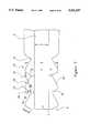
- FIG. 3is a sectional view of a portion of one embodiment of the suction catheter 1 of the instant invention, near its patient contacting or proximal end 4.
- the suction catheter 1is preferably made of a soft PVC material having a rigidity a little stiffer than that of a soft or flexible PVC tube used in conventional suction catheters such as that shown in FIG. 1.
- a suitable rigidity for catheter 1relatively at will because PVC may be made in many degrees of rigidity extending from hard or rigid to soft or flexible. Consequently, it is possible to manufacture a catheter 1 of an appropriate PVC material to satisfy an important requirement of performance for the device that it not bend or twist when inserted into the body lumen A.
- the proximal end 4 of the catheter 1is constructed of a bellowed tubular part 11 extending proximally from straight tubular portion 12 of catheter 1.
- bellowed tubular part 11consists of several sequential "ridges” 13 and “valleys” 14 giving the bellowed tubular part 11 a corrugated appearance.
- the "ridges” 13 and “valley”s 14are annular and extend around the central elongated axis of lumen 3.
- the bellowed tubular part 11may be easily made by a thermal mold process or by other processes that will occur to those skilled in the art.
- each of the "ridges” 13 and “valleys” 14are made of a series of annular proximal flat pieces 16 and distal flat pieces 18.
- Flat pieces 16,18are connected along a common edge at an angle ⁇ to each other to make a "ridge” 13.
- Flat pieces 18,16are connected along a common edge at an angle ⁇ to make a "valley” 14.
- a series of alternating "ridges” 13 and “valleys” 14extend from the proximal end 4 throughout the bellowed tubular part 11 to the straight tubular part 12.
- the preferred angle for both ⁇ and ⁇is approximately 90° but other angles may be used as well, including, but not limited to 60°. Further, differing angles for ⁇ and ⁇ may be used as desired.
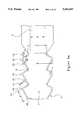
- each "ridge”When viewed in cross-section, each "ridge” will have a "major” diameter B defined as the largest cross-sectional distance across the annular "ridge” 13 and a “minor” diameter C defined as the smallest cross-sectional distance across the annular “valley” 14.
- a series of “ridges”are connected along their edges of “minor” diameter C to form the alternating series of "ridges” 13 and “valleys”14.
- each proximal flat piece 16 and its neighboring distal flat piece 18are identical.
- the width of a flat piece 16,18is defined as the shortest distance from a connecting point between a proximal flat piece 16 and a distal flat piece 18 across the respective flat piece 16,18 to the next distal flat piece 18 or proximal flat piece 16, respectively.
- the resulting "ridge" 13when viewed in cross-section, resembles an isosceles triangle, flat pieces 16,18 being the isosceles legs of the triangle.
- the width E of proximal flat pieces 16is more or less, respectively, than the width F of distal flat pieces 18.
- ridges 13instead of “ridges" 13 resembling isosceles triangles in cross-section, scalene triangles are formed.
- the main lumen 3 of the catheter 1extends through the bellowed tubular part 11 to the proximal end 4 at the same diameter G as the lumen 3 has in the straight tubular part 12.
- the area between flat pieces 16,18 in “ridges” 13is filled with the material of the catheter so that the "ridges" 13 are solid pieces.
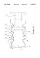
- the "major" and “minor" diameters B,C of the bellowed tubular part 11have constant values for the entire length of the bellowed tubular part 11.
- the "major" diameter B of the bellowed tubular part 11remains constant at approximately the outer diameter of the straight tubular part 12 but the “minor” diameter C of the tubular bellowed part 11 gradually increases moving from the proximal end 4 toward the straight tubular part 12.
- the diameter G of the lumen 3 extending through the tubular bellowed part 11is approximately equal to the diameter G of the lumen 3 in the straight tubular part 12.
- the proximal end 4is made flexible while the rigidity of the catheter 1 gradually increases moving toward the straight tubular portion 12. Consequently, it is possible to provide a suction catheter 1 which doesn't bend and twist during insertion of the catheter 1 into the body lumen A.
- This embodimentallows the portion of the catheter 1 near the opening 7 of the proximal end 4 to have a large flexibility while the stiffness of the bellowed tubular part 11 increases approaching straight tubular part 12 from the opening 7.
- the result of such constructionis to improve the catheter's ability to prevent mucous membranes from injury because of the flexibility of proximal end 4 while still allowing the catheter 1 to be moved and rotated due to the stiffness of the bellowed tubular part 11 near the straight tubular part 12 in order to position the catheter 1.
- both the diameter G of lumen 3 and "major" diameter B of the bellowed tubular portion 11are substantially identical with the diameter G and outer diameter H f the lumen 3 and the straight tubular part 12, respectively.
- the major diameter B of the bellowed tubular part 11is made almost identical with the outer diameter H of the straight tubular part 12, no restriction is given along the whole outer diameter of the catheter 1 because of the bellowed tubular part 11.
- the air flow pattern through and around the suction catheter 1is substantially the same as that of the conventional catheters such as those shown FIG. 1, despite the presence of the bellowed tubular part 11. This allows the suction catheter to attain a good suction efficiency.
- the flat side pieces 16,18 of the "ridges" 13each have a fixed thickness I along substantially their entire width. Thickness I (shown in FIGS. 3a, 5a and 6a, as greatly exaggerated) is preferably thin to allow flat pieces 16,18 to flex at their connecting edges.
- the diameter G of the lumen 3 in the bellowed tubular part 11will be the "minor" diameter C of the bellowed tubular part 11.
- flat pieces 16,18will flex around their connecting points to each other so that angles ⁇ and ⁇ will change. As the bellowed tubular part 11 is compressed or stretched from its relaxed configuration, the changing angles ⁇ and ⁇ will cause the "minor" diameter C, and consequently the diameter G of the lumen 3 through the bellowed tubular part 11, to decrease or increase.
- the increased or decreased "minor" diameter Cwill affect the vacuum pressure present in the bellowed tubular part 11 as vacuum pressure is applied to the main lumen 3 at the distal end 5 of the catheter 1.
- the vacuum pressure presented at the proximal end 4 of the catheter 1may be varied by compressing or relaxing the bellowed tubular part 11 by moving the distal end 5 of the catheter 1 toward and away, respectively, from the proximal end 4 of the catheter 1 while the catheter 1 is in the body lumen A.
- This variable pressurein combination with the variable pressure caused by covering and uncovering suction control hole 10, may assist in moving debris or other material into lumen 3 through end hole 7 and side holes 9.
- annular flange 8is located on the end of the proximal end 4 of the catheter 1.
- This flange 8has a diameter larger than the outer diameter of the straight tubular part 12 or the major diameter B of the bellowed tubular part 11 and extends away from the proximal end 4 at a right angle to the axis of the catheter 1 at the proximal end 4.
- an end hole 7fluidly connects the most proximal end of lumen 3 with the exterior of the catheter 1 at proximal end 4.
- End hole 7is aligned with the axis of lumen 3.
- End hole 7preferably has a diameter approximately equal to the diameter of lumen 3 at proximal end 4 but may also have a larger or smaller diameter as desired.
- several side holes 9are preferably placed through the "valleys” 14 thereby fluidly connecting lumen 3 with the exterior of catheter 1.
- at least one side hole 9is preferably placed on every "valley” 14, it is not necessary to place a side hole 9 on every "valley” 14.
- several side holes 9may be placed on a single “valley” 14. Further, the number of the side holes 9 formed in each "valley” 14 may increase, decrease or remain constant moving away from the proximal end 4 toward the straight tubular part 12.
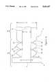
- FIGS. 8 a-cshow cross-sectional views perpendicular to the central axis of suction catheter 1.
- the location of side holes 9 in the "valleys" 14are preferably spaced around the central axis of suction catheter 1.
- FIGS. 8 a, b and cshow the location of two, three and four side holes 9 respectively equally spaced around the central axis of suction catheter 1.
- only one side hole per "valley” 14 or more than four side holes per "valley” 14may be positioned as desired.
- side holes 9may be bunched in groups or not equally spaced as desired.
- side holes 9may be staggered from one "valley” 14 to an adjacent "valley” 14. Staggering means that side holes on adjacent "valleys" are not aligned along an axis parallel to the main axis of lumen 3, but are offset from each other. This staggered arrangement of side holes 9 may produce a wider dispersion of vacuum pressure along the outer surface of catheter 1 than would occur if the side holes 9 were not staggered.
- the proximal end 4 of the suction catheter 1is made of a bellowed tubular part 11 so that the proximal end 4 has an increased and desirable flexibility compared to prior catheters. Consequently, the proximal end 4 of the catheter 1 doesn't strike and hurt the trachea and bronchial tube when the catheter 1 is placed into or retained in position in the trachea or bronchial tube. In addition, the bellowed tubular part 11 does not decrease suction efficiency of the catheter.
- a catheter 1 having the bellowed tubular part 11having a side hole or holes 9 but not having an end hole 7 or having an end hole 7 but not having any side holes 9.
- the "major" diameter B of the bellowed tubular part 11is made identical with that of the straight tubular part 12, so it is possible to freely select the suitable diameter of the catheter 1 according to the desired suction efficiency without compromising the suction efficiency of the catheter.
- the number and angles ⁇ , ⁇ between the "ridges” 13 and “valleys” 14 of the bellowed tubular part 11are not restricted to the specific embodiments described.
- the material of the catheteris not limited to PVC material but may encompass any suitable material for making such catheters as will be well understood by those in the art.
- catheter 1In operation, catheter 1 is inserted into a body lumen A of a patient. Vacuum pressure is provided to catheter 1 through lumen 3 at the distal end 5. When suction control hole 10 is closed, vacuum pressure is provided through lumen 3 to end hole 7 and side hole or holes 9. The pressure differential between body lumen A and lumen 3 causes air to move in body lumen A toward catheter 1. One part of the air will move toward and enter end hole 7. Another part of the air will move toward and enter side hole or holes 9.
- the moving airwill move debris or other articles from within body lumen A into lumen 3 through end hole 7 and side hole or holes 9. After the debris or other article is within lumen 3, vacuum pressure continues to move the debris or other article out of the catheter at the distal end 5.
Landscapes
- Health & Medical Sciences (AREA)
- Heart & Thoracic Surgery (AREA)
- Life Sciences & Earth Sciences (AREA)
- Veterinary Medicine (AREA)
- Anesthesiology (AREA)
- Biomedical Technology (AREA)
- Engineering & Computer Science (AREA)
- Hematology (AREA)
- Pulmonology (AREA)
- Animal Behavior & Ethology (AREA)
- General Health & Medical Sciences (AREA)
- Public Health (AREA)
- Emergency Medicine (AREA)
- Surgery (AREA)
- Vascular Medicine (AREA)
- Media Introduction/Drainage Providing Device (AREA)
Abstract
Description
Claims (16)
Priority Applications (1)
| Application Number | Priority Date | Filing Date | Title |
|---|---|---|---|
| US07/923,191US5431637A (en) | 1992-07-31 | 1992-07-31 | Endotracheal suction catheter |
Applications Claiming Priority (1)
| Application Number | Priority Date | Filing Date | Title |
|---|---|---|---|
| US07/923,191US5431637A (en) | 1992-07-31 | 1992-07-31 | Endotracheal suction catheter |
Publications (1)
| Publication Number | Publication Date |
|---|---|
| US5431637Atrue US5431637A (en) | 1995-07-11 |
Family
ID=25448281
Family Applications (1)
| Application Number | Title | Priority Date | Filing Date |
|---|---|---|---|
| US07/923,191Expired - LifetimeUS5431637A (en) | 1992-07-31 | 1992-07-31 | Endotracheal suction catheter |
Country Status (1)
| Country | Link |
|---|---|
| US (1) | US5431637A (en) |
Cited By (36)
| Publication number | Priority date | Publication date | Assignee | Title |
|---|---|---|---|---|
| US5690620A (en)* | 1996-05-14 | 1997-11-25 | Knott; Michael Mcfarland | Anatomically conforming nasogastric tube with normally-curved tip and method for using same |
| USD398989S (en) | 1997-08-20 | 1998-09-29 | Grant Harris Ashlin | Endotracheal tube |
| US5997506A (en)* | 1998-04-02 | 1999-12-07 | Muzzammel; Mohiuddin M. | Hysterosonogram/hysterosalpingogram cannula with soft seal |
| US6398266B1 (en)* | 1999-09-22 | 2002-06-04 | Ballard Medical Products | Collapse resistant popoid connector |
| USD466607S1 (en) | 2001-08-27 | 2002-12-03 | Kimberly-Clark Worldwide, Inc. | Flexible connector |
| USD473941S1 (en) | 2001-08-27 | 2003-04-29 | Kimberly-Clark Worldwide, Inc. | Flexible connecting device |
| USD476731S1 (en) | 2001-08-27 | 2003-07-01 | Kimberly-Clark Worldwide, Inc. | Bendable connector |
| USD486909S1 (en) | 2001-08-27 | 2004-02-17 | Kimberly-Clark Worldwide, Inc. | Bendable connecting device |
| US20050096582A1 (en)* | 2002-02-25 | 2005-05-05 | Burnett Daniel R. | Implantable fluid management system for the removal of excess fluid |
| US20050235996A1 (en)* | 2004-04-27 | 2005-10-27 | Hooser David Theron V | Clamping assembly for limiting the depth of insertion of a respiratory care treatment device |
| US20060229574A1 (en)* | 2005-03-31 | 2006-10-12 | Sherman Darren R | Catheter shaft with undulating surface for reduced friction |
| US20060253101A1 (en)* | 2005-03-16 | 2006-11-09 | Andreas Hartlep | Intracranial catheter |
| US20070293812A1 (en)* | 2006-06-14 | 2007-12-20 | Wright Clifford A | Respiratory suction catheter assembly |
| US20080154173A1 (en)* | 2002-02-25 | 2008-06-26 | Novashunt Ag | Vesicular shunt for the drainage of excess fluid |
| US20090204065A1 (en)* | 2007-03-29 | 2009-08-13 | Wright Clifford A | Suction wand |
| US20090318844A1 (en)* | 2003-11-03 | 2009-12-24 | Novashunt Ag | Implantable fluid management device for the removal of excess fluid |
| US7913693B2 (en) | 2006-11-10 | 2011-03-29 | Nellcor Puritan Bennett Llc | Method and apparatus for preventing occlusion of a tracheal tube suction lumen |
| US20110144514A1 (en)* | 2009-12-16 | 2011-06-16 | Nellcor Puritan Bennett Llc | Tracheal Tube with Pressure Monitoring Lumen and Method for Using the Same |
| US20110178419A1 (en)* | 2010-01-18 | 2011-07-21 | Nellcor Puritan Bennett Llc | Tracheal tube with pressure monitoring lumen and method for using the same |
| US8157919B2 (en) | 2009-02-06 | 2012-04-17 | Endoclear, Llc | Methods for removing debris from medical tubes |
| US8381345B2 (en) | 2009-02-06 | 2013-02-26 | Endoclear, Llc | Devices for cleaning endotracheal tubes |
| US8783255B2 (en) | 2010-07-30 | 2014-07-22 | Covidien Lp | Medical device tube having suction lumen and an associated suctioning system |
| DE102014203920A1 (en)* | 2014-03-04 | 2015-09-10 | Olympus Winter & Ibe Gmbh | Device for laser lithotripsy |
| WO2016054355A1 (en)* | 2014-10-02 | 2016-04-07 | George Crawford | Suction adapter device |
| US9352112B2 (en) | 2011-12-13 | 2016-05-31 | Covidien Lp | Shaped evacuation port for a multi-lumen tracheal tube |
| US9445714B2 (en) | 2010-03-29 | 2016-09-20 | Endoclear Llc | Endotracheal tube coupling adapters |
| US10004863B2 (en) | 2012-12-04 | 2018-06-26 | Endoclear Llc | Closed suction cleaning devices, systems and methods |
| US10016575B2 (en) | 2014-06-03 | 2018-07-10 | Endoclear Llc | Cleaning devices, systems and methods |
| CN109475668A (en)* | 2016-05-16 | 2019-03-15 | 泰利福生命科学无限责任公司 | Catheter dynamic tip occlusion |
| US10722322B2 (en) | 2010-03-29 | 2020-07-28 | Endoclear Llc | Distal airway cleaning devices |
| US10918778B2 (en) | 2017-05-24 | 2021-02-16 | Sequana Medical Nv | Direct sodium removal method, solution and apparatus to reduce fluid overload in heart failure patients |
| US20230001165A1 (en)* | 2019-11-20 | 2023-01-05 | Massachusetts Institute Of Technology | Cerebrospinal fluid space draining catheters |
| US11559618B2 (en) | 2017-05-24 | 2023-01-24 | Sequana Medical Nv | Formulations and methods for direct sodium removal in patients having severe renal dysfunction |
| US11793916B2 (en) | 2012-02-15 | 2023-10-24 | Sequana Medical Nv | Systems and methods for fluid management |
| US11839712B2 (en) | 2004-08-18 | 2023-12-12 | Sequana Medical Nv | Implantable fluid management system for treating heart failure |
| US11854697B2 (en) | 2016-08-26 | 2023-12-26 | Sequana Medical Nv | Systems and methods for managing and analyzing data generated by an implantable device |
Citations (25)
| Publication number | Priority date | Publication date | Assignee | Title |
|---|---|---|---|---|
| DE408449C (en)* | 1923-10-10 | 1925-01-20 | Kurt Andreas | catheter |
| DE666587C (en)* | 1938-10-22 | Paul Thulcke | After-tubes | |
| US2691373A (en)* | 1951-11-15 | 1954-10-12 | Julien A Bried | Colon flushing nozzle with dissolvable tip |
| US3136316A (en)* | 1962-01-19 | 1964-06-09 | Abbott Lab | Catheter |
| US3516410A (en)* | 1968-01-03 | 1970-06-23 | Salomon Hakim | Cerebro-ventricular catheter |
| US3599642A (en)* | 1967-03-20 | 1971-08-17 | Roland L Tindel | Endotracheal tubes |
| US3618613A (en)* | 1969-05-19 | 1971-11-09 | Heyer Schulte Corp | Antithrombotic intravascular catheter reinforced with nonkinking means |
| US3659611A (en)* | 1969-12-15 | 1972-05-02 | Dow Corning | Tracheal tube seal |
| US3670726A (en)* | 1969-09-23 | 1972-06-20 | Becton Dickinson Co | Breathing circuit |
| US3777757A (en)* | 1971-01-08 | 1973-12-11 | R Gray | Sucking wound plug and chest aspirator |
| US3858615A (en)* | 1972-12-11 | 1975-01-07 | Puritan Bennett Corp | Flexible hose construction |
| US3945385A (en)* | 1974-10-25 | 1976-03-23 | Physicians' Medical Patent Development Corporation | Suction catheter |
| US3963856A (en)* | 1974-11-25 | 1976-06-15 | Steward Plastics, Inc. | Flexible, corrugated, plastic tubing having conductive helical bead |
| DE2528273A1 (en)* | 1975-04-12 | 1976-10-21 | Karl Dr Med Fabian | Prostate gland catheter - is designed for prolonged insertion without causing inflammation or infection |
| US4275724A (en)* | 1979-04-02 | 1981-06-30 | Barry Behrstock | Endotracheal intubation device |
| FR2554352A1 (en)* | 1983-11-04 | 1985-05-10 | Inst Nat Sante Rech Med | Self-immobilising visceral catheter with helicoid coating |
| US4593690A (en)* | 1984-06-28 | 1986-06-10 | David S. Sheridan | Endotracheal tubes with improved proximal end connector units |
| US4717379A (en)* | 1984-06-29 | 1988-01-05 | Mediplast Ab | Catheter, probe or similar device |
| US4781678A (en)* | 1986-03-06 | 1988-11-01 | Imtec S.A. | Surgical drain |
| DE3735927A1 (en)* | 1987-10-23 | 1989-05-03 | Fischer Artur Werke Gmbh | Tube for implantable rinsing suction drainage |
| US4852564A (en)* | 1984-06-28 | 1989-08-01 | Sheridan Catheter Corp. | Flexible connectors for medico-surgical tubes |
| US4950232A (en)* | 1987-08-11 | 1990-08-21 | Surelab Superior Research Laboratories | Cerebrospinal fluid shunt system |
| US4969878A (en)* | 1986-03-18 | 1990-11-13 | Christoph Schmidt | Thick-walled flexible probe for insertion in the trachea or respectively in the bronchial system |
| US4987895A (en)* | 1986-10-06 | 1991-01-29 | Heimlich Henry J | Tracheal tube |
| US5024220A (en)* | 1988-07-21 | 1991-06-18 | Board Of Regents, The University Of Texas System | Nasotracheal tube insertion connector |
- 1992
- 1992-07-31USUS07/923,191patent/US5431637A/ennot_activeExpired - Lifetime
Patent Citations (25)
| Publication number | Priority date | Publication date | Assignee | Title |
|---|---|---|---|---|
| DE666587C (en)* | 1938-10-22 | Paul Thulcke | After-tubes | |
| DE408449C (en)* | 1923-10-10 | 1925-01-20 | Kurt Andreas | catheter |
| US2691373A (en)* | 1951-11-15 | 1954-10-12 | Julien A Bried | Colon flushing nozzle with dissolvable tip |
| US3136316A (en)* | 1962-01-19 | 1964-06-09 | Abbott Lab | Catheter |
| US3599642A (en)* | 1967-03-20 | 1971-08-17 | Roland L Tindel | Endotracheal tubes |
| US3516410A (en)* | 1968-01-03 | 1970-06-23 | Salomon Hakim | Cerebro-ventricular catheter |
| US3618613A (en)* | 1969-05-19 | 1971-11-09 | Heyer Schulte Corp | Antithrombotic intravascular catheter reinforced with nonkinking means |
| US3670726A (en)* | 1969-09-23 | 1972-06-20 | Becton Dickinson Co | Breathing circuit |
| US3659611A (en)* | 1969-12-15 | 1972-05-02 | Dow Corning | Tracheal tube seal |
| US3777757A (en)* | 1971-01-08 | 1973-12-11 | R Gray | Sucking wound plug and chest aspirator |
| US3858615A (en)* | 1972-12-11 | 1975-01-07 | Puritan Bennett Corp | Flexible hose construction |
| US3945385A (en)* | 1974-10-25 | 1976-03-23 | Physicians' Medical Patent Development Corporation | Suction catheter |
| US3963856A (en)* | 1974-11-25 | 1976-06-15 | Steward Plastics, Inc. | Flexible, corrugated, plastic tubing having conductive helical bead |
| DE2528273A1 (en)* | 1975-04-12 | 1976-10-21 | Karl Dr Med Fabian | Prostate gland catheter - is designed for prolonged insertion without causing inflammation or infection |
| US4275724A (en)* | 1979-04-02 | 1981-06-30 | Barry Behrstock | Endotracheal intubation device |
| FR2554352A1 (en)* | 1983-11-04 | 1985-05-10 | Inst Nat Sante Rech Med | Self-immobilising visceral catheter with helicoid coating |
| US4593690A (en)* | 1984-06-28 | 1986-06-10 | David S. Sheridan | Endotracheal tubes with improved proximal end connector units |
| US4852564A (en)* | 1984-06-28 | 1989-08-01 | Sheridan Catheter Corp. | Flexible connectors for medico-surgical tubes |
| US4717379A (en)* | 1984-06-29 | 1988-01-05 | Mediplast Ab | Catheter, probe or similar device |
| US4781678A (en)* | 1986-03-06 | 1988-11-01 | Imtec S.A. | Surgical drain |
| US4969878A (en)* | 1986-03-18 | 1990-11-13 | Christoph Schmidt | Thick-walled flexible probe for insertion in the trachea or respectively in the bronchial system |
| US4987895A (en)* | 1986-10-06 | 1991-01-29 | Heimlich Henry J | Tracheal tube |
| US4950232A (en)* | 1987-08-11 | 1990-08-21 | Surelab Superior Research Laboratories | Cerebrospinal fluid shunt system |
| DE3735927A1 (en)* | 1987-10-23 | 1989-05-03 | Fischer Artur Werke Gmbh | Tube for implantable rinsing suction drainage |
| US5024220A (en)* | 1988-07-21 | 1991-06-18 | Board Of Regents, The University Of Texas System | Nasotracheal tube insertion connector |
Cited By (76)
| Publication number | Priority date | Publication date | Assignee | Title |
|---|---|---|---|---|
| US5690620A (en)* | 1996-05-14 | 1997-11-25 | Knott; Michael Mcfarland | Anatomically conforming nasogastric tube with normally-curved tip and method for using same |
| USD398989S (en) | 1997-08-20 | 1998-09-29 | Grant Harris Ashlin | Endotracheal tube |
| US5997506A (en)* | 1998-04-02 | 1999-12-07 | Muzzammel; Mohiuddin M. | Hysterosonogram/hysterosalpingogram cannula with soft seal |
| US6398266B1 (en)* | 1999-09-22 | 2002-06-04 | Ballard Medical Products | Collapse resistant popoid connector |
| USD466607S1 (en) | 2001-08-27 | 2002-12-03 | Kimberly-Clark Worldwide, Inc. | Flexible connector |
| USD473941S1 (en) | 2001-08-27 | 2003-04-29 | Kimberly-Clark Worldwide, Inc. | Flexible connecting device |
| USD476731S1 (en) | 2001-08-27 | 2003-07-01 | Kimberly-Clark Worldwide, Inc. | Bendable connector |
| USD486909S1 (en) | 2001-08-27 | 2004-02-17 | Kimberly-Clark Worldwide, Inc. | Bendable connecting device |
| US8882699B2 (en) | 2002-02-25 | 2014-11-11 | Sequana Medical Ag | Implantable fluid management system for the removal of excess fluid |
| US8394048B2 (en) | 2002-02-25 | 2013-03-12 | Sequana Medical Ag | Vesicular shunt for the drainage of excess fluid |
| US7909790B2 (en) | 2002-02-25 | 2011-03-22 | Novashunt Ag | Implantable fluid management system for the removal of excess fluid |
| US9913968B2 (en) | 2002-02-25 | 2018-03-13 | Sequana Medical Ag | Implantable fluid management system for the removal of excess fluid |
| US9421347B2 (en) | 2002-02-25 | 2016-08-23 | Sequana Medical Ag | Implantable fluid management system for the removal of excess fluid |
| US20050096582A1 (en)* | 2002-02-25 | 2005-05-05 | Burnett Daniel R. | Implantable fluid management system for the removal of excess fluid |
| US20080154173A1 (en)* | 2002-02-25 | 2008-06-26 | Novashunt Ag | Vesicular shunt for the drainage of excess fluid |
| US8517973B2 (en) | 2002-02-25 | 2013-08-27 | Sequana Medical Ag | Implantable fluid management system for the removal of excess fluid |
| US8771221B2 (en) | 2003-11-03 | 2014-07-08 | Sequana Medical Ag | Implantable fluid management device for the removal of excess fluid |
| US20090318844A1 (en)* | 2003-11-03 | 2009-12-24 | Novashunt Ag | Implantable fluid management device for the removal of excess fluid |
| US8398577B2 (en)* | 2003-11-03 | 2013-03-19 | Sequana Medical Ag | Implantable fluid management device for the removal of excess fluid |
| US20050235996A1 (en)* | 2004-04-27 | 2005-10-27 | Hooser David Theron V | Clamping assembly for limiting the depth of insertion of a respiratory care treatment device |
| US7353822B2 (en) | 2004-04-27 | 2008-04-08 | Kimberly-Clark , Worldwide, Inc. | Clamping assembly for limiting the depth of insertion of a respiratory care treatment device |
| US11839712B2 (en) | 2004-08-18 | 2023-12-12 | Sequana Medical Nv | Implantable fluid management system for treating heart failure |
| US20110066133A1 (en)* | 2005-03-16 | 2011-03-17 | Andreas Hartlep | Intracranial catheter |
| US8469941B2 (en) | 2005-03-16 | 2013-06-25 | Brainlab Ag | Intracranial catheter |
| US20060253101A1 (en)* | 2005-03-16 | 2006-11-09 | Andreas Hartlep | Intracranial catheter |
| US20060229574A1 (en)* | 2005-03-31 | 2006-10-12 | Sherman Darren R | Catheter shaft with undulating surface for reduced friction |
| US7833203B2 (en)* | 2005-03-31 | 2010-11-16 | Cordis Neurovascular, Inc. | Catheter shaft with undulating surface for reduced friction |
| US20070293812A1 (en)* | 2006-06-14 | 2007-12-20 | Wright Clifford A | Respiratory suction catheter assembly |
| US7527058B2 (en) | 2006-06-14 | 2009-05-05 | Medical Device Group, Inc. | Respiratory suction catheter assembly |
| US20110139159A1 (en)* | 2006-11-10 | 2011-06-16 | Nellcor Puritan Bennett Llc | Method and apparatus for preventing occlusion of a tracheal tube suction lumen |
| US7913693B2 (en) | 2006-11-10 | 2011-03-29 | Nellcor Puritan Bennett Llc | Method and apparatus for preventing occlusion of a tracheal tube suction lumen |
| US8012141B2 (en) | 2007-03-29 | 2011-09-06 | Wright Clifford A | Suction wand |
| US20090204065A1 (en)* | 2007-03-29 | 2009-08-13 | Wright Clifford A | Suction wand |
| US9579012B2 (en) | 2009-02-06 | 2017-02-28 | Endoclear Llc | Visualized endotracheal tube placement systems |
| US9855111B2 (en) | 2009-02-06 | 2018-01-02 | Endoclear Llc | Methods of removing biofilm from endotracheal tubes |
| US8534287B2 (en) | 2009-02-06 | 2013-09-17 | Endoclear, Llc | Methods for tracheostomy visualization |
| US8601633B2 (en) | 2009-02-06 | 2013-12-10 | Endoclear Llc | Cleaning of body-inserted medical tubes |
| US8458844B2 (en) | 2009-02-06 | 2013-06-11 | Endoclear, Llc | Medical tube cleaning apparatus |
| US10682203B2 (en) | 2009-02-06 | 2020-06-16 | Endoclear Llc | Methods of cleaning endotracheal tubes including light treatment |
| US8382908B2 (en) | 2009-02-06 | 2013-02-26 | Endoclear, Llc | Methods for cleaning endotracheal tubes |
| US9095286B2 (en) | 2009-02-06 | 2015-08-04 | Endoclear Llc | Body-inserted tube cleaning |
| US10441380B2 (en) | 2009-02-06 | 2019-10-15 | Endoclear Llc | Body-inserted tube cleaning |
| US9962233B2 (en) | 2009-02-06 | 2018-05-08 | Endoclear Llc | Body-inserted tube cleaning |
| US9332891B2 (en) | 2009-02-06 | 2016-05-10 | Endoclear Llc | Tracheostomy visualization |
| US8468637B2 (en) | 2009-02-06 | 2013-06-25 | Endoclear Llc | Mechanically-actuated endotracheal tube cleaning device |
| US8157919B2 (en) | 2009-02-06 | 2012-04-17 | Endoclear, Llc | Methods for removing debris from medical tubes |
| US9386907B2 (en) | 2009-02-06 | 2016-07-12 | Endoclear Llc | Visualization systems and methods |
| US9398837B2 (en) | 2009-02-06 | 2016-07-26 | Endoclear Llc | Methods for confirming placement of endotracheal tubes |
| US8381345B2 (en) | 2009-02-06 | 2013-02-26 | Endoclear, Llc | Devices for cleaning endotracheal tubes |
| US9907624B2 (en) | 2009-02-06 | 2018-03-06 | Endoclear Llc | Body-inserted tube cleaning with suction |
| US20110144514A1 (en)* | 2009-12-16 | 2011-06-16 | Nellcor Puritan Bennett Llc | Tracheal Tube with Pressure Monitoring Lumen and Method for Using the Same |
| US9339208B2 (en) | 2010-01-18 | 2016-05-17 | Covidien Lp | Tracheal tube with pressure monitoring lumen and method for using the same |
| US20110178419A1 (en)* | 2010-01-18 | 2011-07-21 | Nellcor Puritan Bennett Llc | Tracheal tube with pressure monitoring lumen and method for using the same |
| US10722322B2 (en) | 2010-03-29 | 2020-07-28 | Endoclear Llc | Distal airway cleaning devices |
| US9445714B2 (en) | 2010-03-29 | 2016-09-20 | Endoclear Llc | Endotracheal tube coupling adapters |
| US8783255B2 (en) | 2010-07-30 | 2014-07-22 | Covidien Lp | Medical device tube having suction lumen and an associated suctioning system |
| US10682480B2 (en) | 2011-12-13 | 2020-06-16 | Covidien Lp | Shaped evaluation port for a multi-lumen tracheal tube |
| US9352112B2 (en) | 2011-12-13 | 2016-05-31 | Covidien Lp | Shaped evacuation port for a multi-lumen tracheal tube |
| US11793916B2 (en) | 2012-02-15 | 2023-10-24 | Sequana Medical Nv | Systems and methods for fluid management |
| US10821249B2 (en) | 2012-12-04 | 2020-11-03 | Endoclear Llc | Closed suction cleaning devices, systems and methods |
| US10004863B2 (en) | 2012-12-04 | 2018-06-26 | Endoclear Llc | Closed suction cleaning devices, systems and methods |
| US11173266B2 (en) | 2012-12-04 | 2021-11-16 | Endoclear Llc | Closed suction cleaning devices, systems and methods |
| DE102014203920A1 (en)* | 2014-03-04 | 2015-09-10 | Olympus Winter & Ibe Gmbh | Device for laser lithotripsy |
| DE102014203920B4 (en) | 2014-03-04 | 2022-11-24 | Olympus Winter & Ibe Gmbh | Device for laser lithotripsy |
| US10016575B2 (en) | 2014-06-03 | 2018-07-10 | Endoclear Llc | Cleaning devices, systems and methods |
| US10850062B2 (en) | 2014-06-03 | 2020-12-01 | Endoclear Llc | Cleaning devices, systems and methods |
| WO2016054355A1 (en)* | 2014-10-02 | 2016-04-07 | George Crawford | Suction adapter device |
| CN109475668B (en)* | 2016-05-16 | 2021-06-15 | 泰利福生命科学无限责任公司 | catheter dynamic end occlusion |
| CN109475668A (en)* | 2016-05-16 | 2019-03-15 | 泰利福生命科学无限责任公司 | Catheter dynamic tip occlusion |
| US11854697B2 (en) | 2016-08-26 | 2023-12-26 | Sequana Medical Nv | Systems and methods for managing and analyzing data generated by an implantable device |
| US10918778B2 (en) | 2017-05-24 | 2021-02-16 | Sequana Medical Nv | Direct sodium removal method, solution and apparatus to reduce fluid overload in heart failure patients |
| US11602583B2 (en) | 2017-05-24 | 2023-03-14 | Sequana Medical Nv | Direct sodium removal method, solution and apparatus to reduce fluid overload in heart failure patients |
| US11559618B2 (en) | 2017-05-24 | 2023-01-24 | Sequana Medical Nv | Formulations and methods for direct sodium removal in patients having severe renal dysfunction |
| US11844890B2 (en) | 2017-05-24 | 2023-12-19 | Sequana Medical Nv | Formulations and methods for direct sodium removal in patients having heart failure and/or severe renal dysfunction |
| US11464891B2 (en) | 2017-05-24 | 2022-10-11 | Sequana Medical Nv | Implantable pump for direct sodium removal therapy having on-board analyte sensor |
| US20230001165A1 (en)* | 2019-11-20 | 2023-01-05 | Massachusetts Institute Of Technology | Cerebrospinal fluid space draining catheters |
Similar Documents
| Publication | Publication Date | Title |
|---|---|---|
| US5431637A (en) | Endotracheal suction catheter | |
| CA1325943C (en) | Catheter for introduction into the trachea and the bronchial system | |
| US5188592A (en) | Dynamic pressurized catheter with simultaneous oxygen delivery and suction | |
| US6553993B2 (en) | Endotracheal tube with tip directional control and position preserving mechanism | |
| US6761171B2 (en) | Endotracheal tube with tip directional control and position preserving mechanism | |
| US5364358A (en) | Device for controlling the inflation of a balloon catheter | |
| US3991762A (en) | Aspirating device for patient ventilation apparatus | |
| US4762125A (en) | Balloon-tipped suction catheter | |
| EP0112668B1 (en) | Endotracheal tube assembly | |
| US6321749B1 (en) | Endotracheal tube with tip directional control and position preserving mechanism | |
| US5125893A (en) | Suction catheter with wall lumen for irrigation | |
| US6024730A (en) | Catheter assemblies and inner cannulae | |
| US6705321B2 (en) | Laryngeal mask adapter | |
| AU2002239351B2 (en) | Endotracheal tube with tip directional control and position preserving mechanism | |
| US5758656A (en) | Stylet for controlled deformation of a tube | |
| JPH11239618A (en) | Catheter assembly and inside cannula | |
| AU3939293A (en) | Intubation stylet | |
| US20180326169A1 (en) | Endotracheal cleaning suction brush | |
| CN1191794C (en) | Tracheal catheter cleaning device | |
| DE69633288T2 (en) | Improved tracheal tube | |
| JP2023519716A (en) | medical surgical tubing | |
| CA1161720A (en) | Oro-pharyngeal suction airway | |
| CA2329742A1 (en) | Stylet for controlled deformation of a tube | |
| WO2023287962A1 (en) | Multi-cuffed endotracheal tubes | |
| ZA200404049B (en) | Endotracheal tube with tip directional control and position preserving mechanism. |
Legal Events
| Date | Code | Title | Description |
|---|---|---|---|
| AS | Assignment | Owner name:NIPPON SHERWOOD MEDICAL INDUSTRIES, LTD., JAPAN Free format text:ASSIGNMENT OF ASSIGNORS INTEREST;ASSIGNORS:SUZUKI, NOBUAKI;OKADA, YOSUKE;REEL/FRAME:006800/0970 Effective date:19920731 Owner name:SHERWOOD MEDICAL COMPANY, MISSOURI Free format text:ASSIGNMENT OF ASSIGNORS INTEREST;ASSIGNOR:NIPPON SHERWOOD MEDICAL INDUSTRIES, LTD.;REEL/FRAME:006767/0345 Effective date:19920731 Owner name:SHERWOOD MEDICAL COMPANY, MISSOURI Free format text:ASSIGNMENT OF ASSIGNORS INTEREST;ASSIGNOR:KINGHORN, CURTIS D.;REEL/FRAME:006767/0342 Effective date:19921016 | |
| STCF | Information on status: patent grant | Free format text:PATENTED CASE | |
| CC | Certificate of correction | ||
| FPAY | Fee payment | Year of fee payment:4 | |
| AS | Assignment | Owner name:SHERWOOD SERVICES AG, SWITZERLAND Free format text:ASSIGNMENT OF ASSIGNORS INTEREST;ASSIGNOR:TYCO GROUP S.A.R.L.;REEL/FRAME:010180/0294 Effective date:19990406 Owner name:TYCO GROUP S.A.R.L., LUXEMBOURG Free format text:ASSIGNMENT OF ASSIGNORS INTEREST;ASSIGNOR:SHERWOOD MEDICAL COMPANY;REEL/FRAME:010255/0446 Effective date:19990406 | |
| FEPP | Fee payment procedure | Free format text:PAYOR NUMBER ASSIGNED (ORIGINAL EVENT CODE: ASPN); ENTITY STATUS OF PATENT OWNER: LARGE ENTITY | |
| FPAY | Fee payment | Year of fee payment:8 | |
| FPAY | Fee payment | Year of fee payment:12 |