US5431455A - Recreational vehicle sewer hose containment assembly - Google Patents
Recreational vehicle sewer hose containment assemblyDownload PDFInfo
- Publication number
- US5431455A US5431455AUS08/286,508US28650894AUS5431455AUS 5431455 AUS5431455 AUS 5431455AUS 28650894 AUS28650894 AUS 28650894AUS 5431455 AUS5431455 AUS 5431455A
- Authority
- US
- United States
- Prior art keywords
- tube
- collar
- housing
- tip end
- recreational vehicle
- Prior art date
- Legal status (The legal status is an assumption and is not a legal conclusion. Google has not performed a legal analysis and makes no representation as to the accuracy of the status listed.)
- Expired - Lifetime
Links
- 230000008878couplingEffects0.000claimsabstractdescription26
- 238000010168coupling processMethods0.000claimsabstractdescription26
- 238000005859coupling reactionMethods0.000claimsabstractdescription26
- 239000010865sewageSubstances0.000claimsdescription9
- 239000004033plasticSubstances0.000claimsdescription6
- 210000003813thumbAnatomy0.000description17
- 238000010276constructionMethods0.000description4
- 239000000463materialSubstances0.000description3
- 238000000034methodMethods0.000description3
- 239000002184metalSubstances0.000description2
- 238000012986modificationMethods0.000description2
- 230000004048modificationEffects0.000description2
- 230000008602contractionEffects0.000description1
- 238000011010flushing procedureMethods0.000description1
- 238000007689inspectionMethods0.000description1
- 238000004519manufacturing processMethods0.000description1
- 230000013011matingEffects0.000description1
- 239000002699waste materialSubstances0.000description1
Images


Classifications
- F—MECHANICAL ENGINEERING; LIGHTING; HEATING; WEAPONS; BLASTING
- F16—ENGINEERING ELEMENTS AND UNITS; GENERAL MEASURES FOR PRODUCING AND MAINTAINING EFFECTIVE FUNCTIONING OF MACHINES OR INSTALLATIONS; THERMAL INSULATION IN GENERAL
- F16L—PIPES; JOINTS OR FITTINGS FOR PIPES; SUPPORTS FOR PIPES, CABLES OR PROTECTIVE TUBING; MEANS FOR THERMAL INSULATION IN GENERAL
- F16L3/00—Supports for pipes, cables or protective tubing, e.g. hangers, holders, clamps, cleats, clips, brackets
- E—FIXED CONSTRUCTIONS
- E03—WATER SUPPLY; SEWERAGE
- E03F—SEWERS; CESSPOOLS
- E03F1/00—Methods, systems, or installations for draining-off sewage or storm water
- E03F1/008—Temporary fluid connections for emptying mobile sewage holding tanks, e.g. of trailers, boats
Definitions
- the present inventionrelates to a recreational vehicle sewer hose containment assembly and more particularly pertains to holding a sewer hose attached to a recreational vehicle in a stationary position for removal of sewage therefrom with a recreational vehicle sewer hose containment assembly.
- recreational vehicle sewer hose attachmentsThe use of recreational vehicle sewer hose attachments is known in the prior art. More specifically, recreational vehicle sewer hose attachments heretofore devised and utilized for the purpose of removing sewage from a recreational vehicle are known to consist basically of familiar, expected and obvious structural configurations, notwithstanding the myriad of designs encompassed by the crowded prior art which have been developed for the fulfillment of countless objectives and requirements.
- U.S. Pat. No. 3,811,462 to Felizdiscloses a recreational vehicle utility stowage and transfer system.
- U.S. Pat. No. 4,133,347 to Mercerdiscloses a waste evacuation attachment for recreational vehicles.
- U.S. Pat. No. 4,228,978 to Randdiscloses a recreational vehicle sewer hose support.
- U.S. Pat. No. 4,796,926 to Rapsilverdiscloses a dump fitting for sewer hose.
- U.S. Pat. No. 4,905,939 to Horndiscloses a sewer hose supporter.
- U.S. Pat. No. 5,141,017 to Trottierdiscloses a recreational vehicle sewage removal adapter with back-flushing capability.
- the recreational vehicle sewer hose containment assemblysubstantially departs from the conventional concepts and designs of the prior art, and in doing so provides an apparatus primarily developed for the purpose of holding a sewer hose attached to a recreational vehicle in a stationary position for removal of sewage therefrom.
- the present inventionprovides an improved recreational vehicle sewer hose containment assembly.
- the general purpose of the present inventionwhich will be described subsequently in greater detail, is to provide a new and improved recreational vehicle sewer hose containment assembly and method which has all the advantages of the prior art and none of the disadvantages.
- the present inventionessentially comprises, in combination, a first, a second, a third, and a fourth rigid linear plastic tube.
- Each tubehas a central axis, a tip end, and a base end.
- the second, third, and fourth tubeeach further have an elongated slot formed thereon at a location adjacent to each base end. Each slot is aligned with each central axis of each tube.
- the base end of the second tubeis telescopically and frictionally received within the tip end of the first tube
- the base end of the third tubeis telescopically and frictionally received within the tip end of the second tube
- the base end of the fourth tubeis telescopically and frictionally received within the tip end of the third tube to define a housing adapted for receiving a flexible and contractible sewer hose of a recreational vehicle therein.
- the housingis telescopically contractible in a stowed configuration and telescopically extendable in an operable configuration.
- a first, a second, a third, a fourth, and a fifth rigid collaris included with the first collar integrally coupled about the first tube near the base end thereof, the second collar integrally coupled about the tip end of the first tube, the third collar integrally coupled about the tip end of the second tube, the fourth collar integrally coupled about the tip end of the third tube, and the fifth collar integrally coupled to the fourth tube near the tip end thereof.
- the second, third, and fourth collareach have a pair of diametrically opposed, vertically positioned, and threaded upper and lower coupling holes disposed thereon and a pair of diametrically opposed and horizontally positioned eyelets formed thereon.
- Each eyelethas a outwardly angled bore therethrough.
- Each borehas a plurality of spaced projections extended radially inwards adapted for frictionally holding an anchor stake therein.
- a first, a second, and a third rigid thumbscrewis included with the first thumbscrew threadably coupled within the upper coupling hole of the second collar and abuttable against the second tube, the second thumbscrew threadably coupled within the upper coupling hole of the third collar and abuttable against the third tube, and the third thumbscrew threadably coupled within the upper coupling hole of the fourth collar and abuttable against the fourth tube. Tightening the first, second, and third thumbscrews sets the telescopic extension of the second tube from the first tube, the telescopic extension of the third tube from the second tube, and the telescopic extension of the fourth tube from the third tube, respectively.
- Loosening the first, second, and third thumbscrewsallows the telescopic adjustment of the second tube from the first tube, the telescopic adjustment of the third tube from the second tube, and the telescopic adjustment of the fourth tube from the third tube, respectively.
- a first, a second, and a third dog point set screwis included with the first dog point set screw threadably coupled within the lower coupling hole of the second collar and positionable within the slot of the second tube, the second dog point screw threadably coupled within the lower coupling hole of the third collar and positionable within the slot of the third tube, and the third dog point set screw threadably coupled within the lower coupling hole of the fourth collar and positionable within the slot of the fourth tube. Tightening the first, second, and third dog point set screws such that each extends into the respective slot ensures congruent and fixed alignment of the central axes of the tubes of the housing and prevents inadvertent misalignment when a flexible and contractible sewer hose of a recreational vehicle is disposed therein.
- a first, a second, a third, a fourth, and a fifth pair of rigid and elongated anchor stakesis included.
- Each anchor stakehas a head end and a tip end.
- Each anchor stake of the first pairis frictionally coupled within a bore of a separate eyelet on the first collar.
- Each anchor stake of the second pairis frictionally coupled within a bore of a separate eyelet on the second collar.
- Each anchor stake of the third pairis frictionally coupled within a bore of a separate eyelet on the third collar.
- Each anchor stake of the fourth pairis frictionally coupled within a bore of a separate eyelet on the fourth collar.
- Each anchor stake of the fifth pairis frictionally coupled within a bore of a separate eyelet on the fifth collar.
- the tip ends of the stakesare adapted to be pushed into a recipient surface therebelow for placing the housing in a stationary operable configuration.
- a rackis included and formed of two elongated, spaced, and aligned holding members. Each holding member is coupled to the first tube.
- the holding membershave symmetrically opposed pin snaps formed thereon for holding the first, second, third, fourth, and fifth pairs of anchor stakes in a stowed configuration such that the pairs are aligned in parallel with the central axes of the tubes.
- a base end cap and a tip end capare included with the base end cap coupleable over the base end of the first tube and the tip end cap coupleable over the tip end of the fourth tube for allowing a contractible recreational vehicle sewer hose to be held in a stowed configuration within the housing.
- An even further object of the present inventionis to provide a new and improved recreational vehicle sewer hose containment assembly which is susceptible of a low cost of manufacture with regard to both materials and labor, and which accordingly is then susceptible of low prices of sale to the consuming public, thereby making such a recreational vehicle sewer hose containment assembly economically available to the buying public.
- Still yet another object of the present inventionis to provide a new and improved recreational vehicle sewer hose containment assembly which provides in the apparatuses and methods of the prior art some of the advantages thereof, while simultaneously overcoming some of the disadvantages normally associated therewith.
- Even still another object of the present inventionis to provide a new and improved recreational vehicle sewer hose containment assembly for holding a sewer hose attached to a recreational vehicle in a stationary position for removal of sewage therefrom.
- a new and improved recreational vehicle sewer hose containment assemblycomprising a plurality of rigid linear tubes telescopically mated to define a housing, with the housing adapted for receiving a sewer hose of a recreational vehicle therein and with the housing contractible in a stowed configuration and extendable in an operable configuration; adjustment means coupled to the housing for fixedly setting the telescopic extension and alignment of the tubes thereof; and coupling means coupleable to the housing and coupleable with a recipient surface therebelow for placing the housing in a stationary operable configuration.
- FIG. 1is a perspective view of two embodiments of the present invention secured about a sewer hose of a recreational vehicle.
- FIG. 2is a perspective view of the preferred embodiment constructed in accordance with the principles of the present invention in an operable configuration.
- FIG. 3is a plan view of the present invention in a stowed configuration.
- FIG. 4is a side-elevational view of the present invention secured within a recipient surface therebelow.
- FIG. 5is a cross-sectional view of the present invention taken along the line 5--5 of FIG. 4.
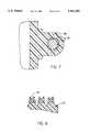
- FIG. 6is a cross-sectional view of a thumb screw used for holding two mated tubes of the present invention at a selected telescopic extension.
- FIG. 7is a cross-sectional view of the coupling between an eyelet of a tube and an anchor stake taken along the line 7--7 of FIG. 4.
- FIG. 8is a cross-sectional view of the coupling between the rack and the anchor stakes in a stowed configuration.
- FIGS. 2 through 8With reference now to the drawings, and in particular, to FIGS. 2 through 8 thereof, the preferred embodiment of the new and improved recreational vehicle sewer hose containment assembly embodying the principles and concepts of the present invention and generally designated by the reference number 10 will be described.
- the present inventionincludes six major components.
- the major componentsare the tubes, thumb screws, dog point set screws, anchor stakes, rack, and caps. These components are interrelated to provide the intended function.
- the first major componentis the tubes.
- the present inventionincludes a first tube 12, a second tube 14, a third tube 16, and a fourth tube 18.
- the first, second, third, and fourth tubesare rigid and linear in structure and formed of plastic.
- Each tubehas a central axis, a tip end, and a base end.
- the second, third, and fourth tubeseach further include an elongated slot 20 formed thereon. Each slot is positioned at a location adjacent to the base end of each tube and aligned with the central axis thereof.
- the base end 22 of the second tubeis telescopically and frictionally received within the tip end 24 of the first tube.
- the base end of the third tube 26is telescopically and frictionally received within the tip end 28 of the second tube.
- the base end 30 of the fourth tubeis telescopically and frictionally received within the tip end 32 of the third tube.
- the telescopic mating of the first, second, third, and fourth tubesdefine a housing 34 adapted for receiving a flexible and contractible sewer hose of a recreational vehicle therein.
- the housingis telescopically contractible in a stowed configuration and telescopically extendable in an operable configuration.
- Each tubealso includes one or more integral collars.
- the first tube 12includes a first collar 40 integrally coupled thereto near the base end 50 thereof.
- the first tubealso includes a second collar 42 integrally coupled thereto at the tip end 24 thereof.
- the second tubeincludes a third collar 44 integrally coupled thereto at the tip end 28 thereof.
- the third tube 16includes a fourth collar 46 integrally coupled thereto at the tip end 32 thereof.
- the fourth tube 18includes a fifth collar 48 integrally coupled thereto near the tip end 52 thereof.
- the second, third, and fourth collareach have a pair of diametrically opposed, vertically positioned, and threaded upper and lower coupling holes 54, 56 disposed thereon.
- the second, third, and fourth collareach further have a pair of diametrically opposed and horizontally positioned eyelets 58 formed thereon.
- Each eyelethas a downwardly projected and outwardly angled bore therethrough.
- Each borehas a plurality of spaced projections 60 extended radially inwards therefrom. These projections are adapted for frictionally holding an anchor stake within the bore.
- the second major componentis the thumb screws.
- the present inventionincludes a first thumb screw 70, a second thumb screw 72, and a third thumb screw 74.
- Each thumb screwis rigid in structure and has a threaded end and a knurled head for allowing a user a firm grip.
- the first thumb screwis threadably coupled within the upper coupling hole of the second collar 42 and abuttable against the second tube 14.
- the second thumb screwis threadably coupled within the upper coupling hole of the third collar 44 and abuttable against the third tube 16.
- the third thumb screwis threadably coupled within the upper coupling hole of the fourth collar 46 and abuttable against the fourth tube 18. Tightening the first thumb screw sets the telescopic extension of the second tube from the first tube.
- Tightening the second thumb screwsets the telescopic extension of the third tube from the second tube. Tightening the third thumb screw sets the telescopic extension of the fourth tube from the third tube.
- loosening the first thumb screwallows the telescopic adjustment of the second tube from the first tube.
- Loosening the second thumb screwallows the telescopic adjustment of the third tube from the second tube.
- loosening the third thumb screwallows the telescopic adjustment of the fourth tube from the third tube.
- the third major componentis the dog point set screws.
- the present inventionincludes a first dog point set screw 80, a second dog point set screw, and a third dog point set screw.
- Each dog point set screwis rigid in structure and has a threaded end and a recessed socket head adapted for receiving a wrench.
- the first dog point set screw 80is threadably coupled within the lower coupling hole of the second collar 42 and positionable within the slot of the second tube.
- the second dog point set screwis threadably coupled within the lower coupling hole of the third collar 44 and positionable within the slot of the third tube 16.
- the third dog point set screwis threadably coupled within the lower coupling hole of the fourth collar 46 and positionable within the slot of the fourth tube 18.
- first dog point set screwTightening the first dog point set screw, the second dog point set screw, and the third dog point set screw such that each extends into its respective corresponding slot insures congruent and fixed alignment of the central axes of the tubes of the housing. Furthermore, the coupling of the dog point set screws within the slots of the tubes prevents inadvertent misalignment of the housing when a flexible and contractible sewer hose is disposed therein.
- the fourth major componentis the anchor stakes.
- the present inventionincludes a first pair of anchor stakes 90, a second pair of anchor stakes 92, a third pair of anchor stakes 94, a fourth pair of anchor stakes 96, and a fifth pair of anchor stakes 98.
- Each anchor stakeis elongated and rigid in structure.
- Each anchor stakeis formed of metal, plastic, or other similar rigid material.
- Each anchor stakehas a head end 100 and a tip end 102.
- Each anchor stake of the first pairis frictionally coupled within a bore of a separate eyelet on the first collar 40.
- Each anchor stake of the second pairis frictionally coupled within a bore of a separate eyelet on the second collar 42.
- Each anchor stake of the third pairis frictionally coupled within a bore of a separate eyelet on the third collar 44.
- Each anchor stake of the fourth pairis frictionally coupled within a bore of a separate eyelet on the fourth collar 46.
- each anchor stake of the fifth pairis frictionally coupled within a bore of a separate eyelet on the fifth collar 48.
- the tip ends of each of the anchor stakesis adapted to be pushed into a recipient surface 104 such as dirt, turf, snow, or the like therebelow for placing the housing in a stationary operable configuration.
- the fifth major componentis the rack 110.
- the rackis rigid in structure and formed of plastic or metal.
- the rackis formed with two elongated, spaced, and aligned holding members 112. Each holding member is coupled to the first tube 12.
- Each holding memberincludes pin snaps 114 formed thereon.
- the pin snapsare used for holding the first pair of anchor stakes 90, the second pair of anchor stakes 92, the third pair of anchor stakes 94, the fourth pair of anchor stakes 96, and the fifth pair of anchor stakes 98 in a stowed configuration.
- the pin snaps on the holding membersare symmetrically aligned such that the pairs of anchor stakes are positioned in parallel with the central axes of the tubes when placed in the stowed configuration.
- the sixth major componentis the caps.
- the present inventionincludes a rubber base end cap 120 and a rubber tip end cap 122.
- the base end capis coupleable over the base end 50 of the first tube.
- the tip end capis coupleable over the tip end 52 of the fourth tube.
- the end capsallow a contractible recreational vehicle sewer hose to be held in a stowed configuration within the housing for transport with a recreational vehicle.
- the present inventionis plastic, tubular telescoping housing for a flexible contractible recreational vehicle or trailer sewer hose.
- the present inventionsimplifies the dumping of sewage from holding tanks of a recreational vehicle.
- the present inventionserves for convenient and proper sewer hookup at any recreational vehicle park.
- the preferred embodimentconsists of four telescoping tubes. These are kept in alignment by a grooves on the tubes and dog point set screws.
- the telescopic extension of the housingcan be set by tightening the three thumb screw knobs and thereby prevent contraction thereof due to the natural shrinking property of the flexible contractible sewer hose.
- the present invention's ten adjustable anchor stakescan be inserted into a recipient surface at a variety of depths. The legs are angled for stability.
- the anchor stakeshold their set position by friction within the bore of each eyelet.
- the anchor stakesmay be independently adjusted by simply pushing or pulling each to a desired position, thereby eliminating the need to level the housing on uneven terrain.
- Additional embodiments of the present invention in sequencemay be disposed about a recreational vehicle sewer hose to accommodate its length or to maneuver it around objects.
- the rack coupled to the housingis used for placing the anchor stakes in a stowed configuration.
- the present inventionis portable and easy to store. Rubber end caps are coupleable either end for allowing sewer hose containment in a stowed configuration within the housing.
- the approximate weight of the present inventionis 12 lbs.
- the length of the present inventioncan vary to accommodate a sewer hose.
- the preferred diameter of the housing of the present inventionis about 5 inches.
Landscapes
- Engineering & Computer Science (AREA)
- General Engineering & Computer Science (AREA)
- Mechanical Engineering (AREA)
- Health & Medical Sciences (AREA)
- Life Sciences & Earth Sciences (AREA)
- Hydrology & Water Resources (AREA)
- Public Health (AREA)
- Water Supply & Treatment (AREA)
- Sewage (AREA)
Abstract
Description
Claims (2)
Priority Applications (1)
| Application Number | Priority Date | Filing Date | Title |
|---|---|---|---|
| US08/286,508US5431455A (en) | 1994-08-05 | 1994-08-05 | Recreational vehicle sewer hose containment assembly |
Applications Claiming Priority (1)
| Application Number | Priority Date | Filing Date | Title |
|---|---|---|---|
| US08/286,508US5431455A (en) | 1994-08-05 | 1994-08-05 | Recreational vehicle sewer hose containment assembly |
Publications (1)
| Publication Number | Publication Date |
|---|---|
| US5431455Atrue US5431455A (en) | 1995-07-11 |
Family
ID=23098933
Family Applications (1)
| Application Number | Title | Priority Date | Filing Date |
|---|---|---|---|
| US08/286,508Expired - LifetimeUS5431455A (en) | 1994-08-05 | 1994-08-05 | Recreational vehicle sewer hose containment assembly |
Country Status (1)
| Country | Link |
|---|---|
| US (1) | US5431455A (en) |
Cited By (30)
| Publication number | Priority date | Publication date | Assignee | Title |
|---|---|---|---|---|
| USD385248S (en)* | 1995-12-27 | 1997-10-21 | Raymond Scott Spiegel | Hose trough for tank truck |
| US5788193A (en)* | 1996-07-15 | 1998-08-04 | Hilbert; Gary A. | Support system for a recreational vehicle drain hose |
| US6186449B1 (en)* | 1999-06-30 | 2001-02-13 | Robert A. Chrestenson | Waste discharge conduit support |
| US6510608B1 (en) | 2000-08-25 | 2003-01-28 | George J. Marshall | Habitable vehicle utility docking apparatus and method |
| US20030047946A1 (en)* | 2001-09-07 | 2003-03-13 | Harout Ohanesian | Joint system for water well conduit assemblies |
| US6619596B1 (en) | 2002-05-02 | 2003-09-16 | Donald R. Caine | RV sewer hose support |
| US20040256007A1 (en)* | 2001-07-16 | 2004-12-23 | James Kennedy | Waste disposal system for recreational vehicles |
| US20040262913A1 (en)* | 2003-06-25 | 2004-12-30 | Anderson Bobby John | Security device for sewer line |
| US20050230571A1 (en)* | 2004-04-20 | 2005-10-20 | Kochanski Jerome J | Hold down device |
| US20070235096A1 (en)* | 2006-04-11 | 2007-10-11 | Nielsen Victor D | Self-contained rigid telescoping drain conduit for recreational vehicles |
| US7400983B2 (en) | 2002-12-20 | 2008-07-15 | Dako Denmark A/S | Information notification sample processing system and methods of biological slide processing |
| USD591407S1 (en) | 2008-07-08 | 2009-04-28 | Ipex Inc. | Pipe having a spigot end and a bell end |
| US20100018590A1 (en)* | 2008-03-13 | 2010-01-28 | Thetford Corporation | Drain system |
| US20100045029A1 (en)* | 2008-08-22 | 2010-02-25 | Younes Youssef | Axially-tensioned pipe joint |
| USD612912S1 (en) | 2009-03-13 | 2010-03-30 | Thetford Corporation | Drain connector |
| USD613827S1 (en) | 2009-03-13 | 2010-04-13 | Thetford Corporation | Hose fitting |
| USD613826S1 (en) | 2009-03-13 | 2010-04-13 | Thetford Corporation | Drain adaptor |
| US20110132485A1 (en)* | 2009-11-30 | 2011-06-09 | Norco Industries, Inc. | Termination valve extension |
| US20140216588A1 (en)* | 2013-02-05 | 2014-08-07 | Chad Tasch | System and Method for Irrigating Liquids Over an Obstacle |
| US8882058B2 (en)* | 2011-05-17 | 2014-11-11 | Dennis Marshall | Sewer-hose-supporting-and-protecting system having quick-release stake-clamping screws, quick-release jaw-squeezing nuts, multi-purpose two-way stakes, and sequential-locking joints |
| USD736601S1 (en) | 2013-11-19 | 2015-08-18 | James R. Cox | Hose support device |
| US9211847B1 (en) | 2014-04-21 | 2015-12-15 | James R. Cox | Hose landing system kit RVS and the like |
| US9365168B2 (en) | 2014-07-16 | 2016-06-14 | Yvan Boutin | Collapsible support structure for flexible hoses |
| US9631355B1 (en)* | 2016-05-11 | 2017-04-25 | Stanley Taraszkiewicz | Septic drainage system |
| US11384522B2 (en)* | 2017-09-26 | 2022-07-12 | Christopher Lombardo | System for stormwater discharge |
| US11435010B1 (en) | 2021-06-10 | 2022-09-06 | Harry Bridges | Hose stand assembly |
| US20230076086A1 (en)* | 2021-09-09 | 2023-03-09 | Ryan Christopher Akin | Manually operated, nonpowered waste disposal system for a recreational vehicle |
| US11821551B1 (en) | 2022-07-07 | 2023-11-21 | Etn Capital, Llc | Hose support assembly |
| US11940071B1 (en)* | 2022-01-25 | 2024-03-26 | Brad Eric Senick | Portable carrier device for RV sewer hoses |
| USD1044484S1 (en)* | 2024-01-02 | 2024-10-01 | Bin KONG | Sewer hose support |
Citations (10)
| Publication number | Priority date | Publication date | Assignee | Title |
|---|---|---|---|---|
| US958752A (en)* | 1909-12-15 | 1910-05-24 | Zeiss Carl Fa | Telescopic tube. |
| US3493204A (en)* | 1967-11-24 | 1970-02-03 | Melvin L Prouty | Adjustable supports for and/or incorporated in liquid conduits used principally in conjunction with waste systems of travel trailers and mobile homes |
| US3730228A (en)* | 1972-01-05 | 1973-05-01 | P Gibbs | Hose-case assembly |
| US3819137A (en)* | 1972-04-20 | 1974-06-25 | H Smith | Trestle for a flexible hose |
| US3951436A (en)* | 1973-09-17 | 1976-04-20 | Midwest Electric Manufacturing Company | Water resistant conduit fitting |
| US4169571A (en)* | 1978-04-04 | 1979-10-02 | Duggan William G | Hose cradles |
| US4223702A (en)* | 1978-12-26 | 1980-09-23 | James Cook | Drain line for recreational vehicles |
| US4228978A (en)* | 1978-10-16 | 1980-10-21 | Roger Rand | Recreational vehicle sewer hose support |
| US4406434A (en)* | 1981-09-28 | 1983-09-27 | Schneckloth Raymond C | Recreational vehicle drain support |
| US4844121A (en)* | 1988-10-12 | 1989-07-04 | Duke Robert L | RV sewage line assembly |
- 1994
- 1994-08-05USUS08/286,508patent/US5431455A/ennot_activeExpired - Lifetime
Patent Citations (10)
| Publication number | Priority date | Publication date | Assignee | Title |
|---|---|---|---|---|
| US958752A (en)* | 1909-12-15 | 1910-05-24 | Zeiss Carl Fa | Telescopic tube. |
| US3493204A (en)* | 1967-11-24 | 1970-02-03 | Melvin L Prouty | Adjustable supports for and/or incorporated in liquid conduits used principally in conjunction with waste systems of travel trailers and mobile homes |
| US3730228A (en)* | 1972-01-05 | 1973-05-01 | P Gibbs | Hose-case assembly |
| US3819137A (en)* | 1972-04-20 | 1974-06-25 | H Smith | Trestle for a flexible hose |
| US3951436A (en)* | 1973-09-17 | 1976-04-20 | Midwest Electric Manufacturing Company | Water resistant conduit fitting |
| US4169571A (en)* | 1978-04-04 | 1979-10-02 | Duggan William G | Hose cradles |
| US4228978A (en)* | 1978-10-16 | 1980-10-21 | Roger Rand | Recreational vehicle sewer hose support |
| US4223702A (en)* | 1978-12-26 | 1980-09-23 | James Cook | Drain line for recreational vehicles |
| US4406434A (en)* | 1981-09-28 | 1983-09-27 | Schneckloth Raymond C | Recreational vehicle drain support |
| US4844121A (en)* | 1988-10-12 | 1989-07-04 | Duke Robert L | RV sewage line assembly |
Cited By (58)
| Publication number | Priority date | Publication date | Assignee | Title |
|---|---|---|---|---|
| USD385248S (en)* | 1995-12-27 | 1997-10-21 | Raymond Scott Spiegel | Hose trough for tank truck |
| US5788193A (en)* | 1996-07-15 | 1998-08-04 | Hilbert; Gary A. | Support system for a recreational vehicle drain hose |
| US6186449B1 (en)* | 1999-06-30 | 2001-02-13 | Robert A. Chrestenson | Waste discharge conduit support |
| US6510608B1 (en) | 2000-08-25 | 2003-01-28 | George J. Marshall | Habitable vehicle utility docking apparatus and method |
| US20030070284A1 (en)* | 2000-08-25 | 2003-04-17 | George Marshall | Habitable Vehicle Utility Docking Apparatus and Method |
| US6712619B2 (en) | 2000-08-25 | 2004-03-30 | George J. Marshall | Habitable vehicle utility docking apparatus and method |
| US7036524B2 (en) | 2001-07-16 | 2006-05-02 | James Kennedy | Waste disposal system for recreational vehicles |
| US20040256007A1 (en)* | 2001-07-16 | 2004-12-23 | James Kennedy | Waste disposal system for recreational vehicles |
| US20030047946A1 (en)* | 2001-09-07 | 2003-03-13 | Harout Ohanesian | Joint system for water well conduit assemblies |
| US6619596B1 (en) | 2002-05-02 | 2003-09-16 | Donald R. Caine | RV sewer hose support |
| US8257968B2 (en) | 2002-12-20 | 2012-09-04 | Dako Denmark A/S | Method and apparatus for automatic staining of tissue samples |
| US8529836B2 (en) | 2002-12-20 | 2013-09-10 | Dako Denmark A/S | Apparatus for automated processing biological samples |
| US10156580B2 (en) | 2002-12-20 | 2018-12-18 | Dako Denmark A/S | Information notification sample processing system and methods of biological slide processing |
| US7400983B2 (en) | 2002-12-20 | 2008-07-15 | Dako Denmark A/S | Information notification sample processing system and methods of biological slide processing |
| US9778273B2 (en) | 2002-12-20 | 2017-10-03 | Dako Denmark A/S | Isolated communication sample processing system and methods of biological slide processing |
| US7648678B2 (en) | 2002-12-20 | 2010-01-19 | Dako Denmark A/S | Method and system for pretreatment of tissue slides |
| US9599630B2 (en) | 2002-12-20 | 2017-03-21 | Dako Denmark A/S | Method and apparatus for automatic staining of tissue samples |
| US9229016B2 (en) | 2002-12-20 | 2016-01-05 | Dako Denmark A/S | Information notification sample processing system and methods of biological slide processing |
| US8969086B2 (en) | 2002-12-20 | 2015-03-03 | Dako Denmark A/S | Enhanced scheduling sample processing system and methods of biological slide processing |
| US8788217B2 (en) | 2002-12-20 | 2014-07-22 | Dako Denmark A/S | Information notification sample processing system and methods of biological slide processing |
| US8784735B2 (en) | 2002-12-20 | 2014-07-22 | Dako Denmark A/S | Apparatus for automated processing biological samples |
| US8673642B2 (en) | 2002-12-20 | 2014-03-18 | Dako Denmark A/S | Enhanced scheduling sample processing system and methods of biological slide processing |
| US7758809B2 (en) | 2002-12-20 | 2010-07-20 | Dako Cytomation Denmark A/S | Method and system for pretreatment of tissue slides |
| US7937228B2 (en) | 2002-12-20 | 2011-05-03 | Dako Denmark A/S | Information notification sample processing system and methods of biological slide processing |
| US8663978B2 (en) | 2002-12-20 | 2014-03-04 | Dako Denmark A/S | Method and apparatus for automatic staining of tissue samples |
| US7960178B2 (en) | 2002-12-20 | 2011-06-14 | Dako Denmark A/S | Enhanced scheduling sample processing system and methods of biological slide processing |
| US8394635B2 (en) | 2002-12-20 | 2013-03-12 | Dako Denmark A/S | Enhanced scheduling sample processing system and methods of biological slide processing |
| US8216512B2 (en) | 2002-12-20 | 2012-07-10 | Dako Denmark A/S | Apparatus for automated processing biological samples |
| US8386195B2 (en) | 2002-12-20 | 2013-02-26 | Dako Denmark A/S | Information notification sample processing system and methods of biological slide processing |
| US8298815B2 (en) | 2002-12-20 | 2012-10-30 | Dako Denmark A/S | Systems and methods of sample processing and temperature control |
| US20040262913A1 (en)* | 2003-06-25 | 2004-12-30 | Anderson Bobby John | Security device for sewer line |
| US20050230571A1 (en)* | 2004-04-20 | 2005-10-20 | Kochanski Jerome J | Hold down device |
| US7731133B2 (en) | 2004-04-20 | 2010-06-08 | Kochanski Jerome J | Hold down device |
| US20070235096A1 (en)* | 2006-04-11 | 2007-10-11 | Nielsen Victor D | Self-contained rigid telescoping drain conduit for recreational vehicles |
| US8826939B2 (en) | 2008-03-13 | 2014-09-09 | Thetford Corporation | Drain system |
| US20100018590A1 (en)* | 2008-03-13 | 2010-01-28 | Thetford Corporation | Drain system |
| USD591407S1 (en) | 2008-07-08 | 2009-04-28 | Ipex Inc. | Pipe having a spigot end and a bell end |
| US8007014B2 (en) | 2008-08-22 | 2011-08-30 | Younes Youssef | Axially-tensioned pipe joint |
| US20100045029A1 (en)* | 2008-08-22 | 2010-02-25 | Younes Youssef | Axially-tensioned pipe joint |
| USD613827S1 (en) | 2009-03-13 | 2010-04-13 | Thetford Corporation | Hose fitting |
| USD613826S1 (en) | 2009-03-13 | 2010-04-13 | Thetford Corporation | Drain adaptor |
| USD612912S1 (en) | 2009-03-13 | 2010-03-30 | Thetford Corporation | Drain connector |
| US8469049B2 (en)* | 2009-11-30 | 2013-06-25 | Norco Industries, Inc. | Termination valve extension |
| US20110132485A1 (en)* | 2009-11-30 | 2011-06-09 | Norco Industries, Inc. | Termination valve extension |
| US8882058B2 (en)* | 2011-05-17 | 2014-11-11 | Dennis Marshall | Sewer-hose-supporting-and-protecting system having quick-release stake-clamping screws, quick-release jaw-squeezing nuts, multi-purpose two-way stakes, and sequential-locking joints |
| US20140216588A1 (en)* | 2013-02-05 | 2014-08-07 | Chad Tasch | System and Method for Irrigating Liquids Over an Obstacle |
| USD736601S1 (en) | 2013-11-19 | 2015-08-18 | James R. Cox | Hose support device |
| US9211847B1 (en) | 2014-04-21 | 2015-12-15 | James R. Cox | Hose landing system kit RVS and the like |
| US9365168B2 (en) | 2014-07-16 | 2016-06-14 | Yvan Boutin | Collapsible support structure for flexible hoses |
| US9631355B1 (en)* | 2016-05-11 | 2017-04-25 | Stanley Taraszkiewicz | Septic drainage system |
| US11384522B2 (en)* | 2017-09-26 | 2022-07-12 | Christopher Lombardo | System for stormwater discharge |
| US11435010B1 (en) | 2021-06-10 | 2022-09-06 | Harry Bridges | Hose stand assembly |
| US20230076086A1 (en)* | 2021-09-09 | 2023-03-09 | Ryan Christopher Akin | Manually operated, nonpowered waste disposal system for a recreational vehicle |
| US11940071B1 (en)* | 2022-01-25 | 2024-03-26 | Brad Eric Senick | Portable carrier device for RV sewer hoses |
| US11821551B1 (en) | 2022-07-07 | 2023-11-21 | Etn Capital, Llc | Hose support assembly |
| US12044341B2 (en) | 2022-07-07 | 2024-07-23 | Etn Capital, Llc | Hose support assembly |
| US12359751B2 (en) | 2022-07-07 | 2025-07-15 | Etn Capital, Llc | Hose support assembly |
| USD1044484S1 (en)* | 2024-01-02 | 2024-10-01 | Bin KONG | Sewer hose support |
Similar Documents
| Publication | Publication Date | Title |
|---|---|---|
| US5431455A (en) | Recreational vehicle sewer hose containment assembly | |
| US3304035A (en) | Golf cart umbrella attachment | |
| US5269554A (en) | Trailer hitch alignment guide | |
| US6438889B1 (en) | Fishing rod support apparatus | |
| US5322250A (en) | Foldable support leg assembly | |
| US11178959B1 (en) | Support pole system for supporting articles | |
| US5813164A (en) | Fishing rod holder | |
| US5524855A (en) | Umbrella post sand anchor | |
| US6099035A (en) | Wheeled or vehicle-mounted cart apparatus | |
| US4164233A (en) | Vehicle covering apparatus | |
| US5518156A (en) | Cooker mounting assembly for attachment to a vehicle | |
| US5620191A (en) | Multiple purpose sled | |
| US4192076A (en) | Device for holding a surveyor's instrument | |
| DE3237420A1 (en) | MUSICAL INSTRUMENT STAND | |
| US6409611B1 (en) | Golf swing training umbrella and golf ball retrieving device | |
| US5507541A (en) | Ball retrieval cart | |
| US5299381A (en) | Christmas tree stand apparatus | |
| US5561937A (en) | Fishing rod holder | |
| US5263278A (en) | Plant stem protector apparatus | |
| US5071118A (en) | Illuminated jump rope apparatus | |
| US5097909A (en) | Garden trowel tool kit | |
| GB2201322A (en) | Angling aid | |
| US5709373A (en) | Portable ski and snowboard tuning table | |
| US5280891A (en) | Pipe welding support apparatus | |
| US5642844A (en) | Tree stand carrier for an ATV |
Legal Events
| Date | Code | Title | Description |
|---|---|---|---|
| STCF | Information on status: patent grant | Free format text:PATENTED CASE | |
| FPAY | Fee payment | Year of fee payment:4 | |
| FPAY | Fee payment | Year of fee payment:8 | |
| AS | Assignment | Owner name:DELANEY, EDWARD, WASHINGTON Free format text:ASSIGNMENT OF ASSIGNORS INTEREST;ASSIGNOR:JOHNSTON, LEGAL REPRESENTATIVE OF ESTATE OF STANLEY SEELY (DECEASED), MARLYS;REEL/FRAME:016712/0827 Effective date:20050215 Owner name:JOHNSTON, LEGAL REPRESENTATIVE OF ESTATE OF STANLE Free format text:SECURITY AGREEMENT;ASSIGNOR:DELANEY, EDWARD;REEL/FRAME:016712/0846 Effective date:20050215 | |
| FEPP | Fee payment procedure | Free format text:PAYOR NUMBER ASSIGNED (ORIGINAL EVENT CODE: ASPN); ENTITY STATUS OF PATENT OWNER: SMALL ENTITY | |
| FPAY | Fee payment | Year of fee payment:12 | |
| AS | Assignment | Owner name:DELANEY, EDWARD, WASHINGTON Free format text:RELEASE OF SECURITY AGREEMENT;ASSIGNOR:JOHNSTON, MARLYS, LEGAL REPRESENTATIVE OF THE ESTATE OF STANLEY SEELY, DECEASED;REEL/FRAME:019511/0455 Effective date:20070228 |