US5431166A - Low profile medical electrode - Google Patents
Low profile medical electrodeDownload PDFInfo
- Publication number
- US5431166A US5431166AUS08/007,446US744693AUS5431166AUS 5431166 AUS5431166 AUS 5431166AUS 744693 AUS744693 AUS 744693AUS 5431166 AUS5431166 AUS 5431166A
- Authority
- US
- United States
- Prior art keywords
- electrode
- base sheet
- tab
- skin
- connector
- Prior art date
- Legal status (The legal status is an assumption and is not a legal conclusion. Google has not performed a legal analysis and makes no representation as to the accuracy of the status listed.)
- Expired - Lifetime
Links
- 239000011262electrochemically active materialSubstances0.000claimsdescription14
- 230000001070adhesive effectEffects0.000claimsdescription13
- 239000000853adhesiveSubstances0.000claimsdescription12
- 239000003792electrolyteSubstances0.000claimsdescription9
- 239000004020conductorSubstances0.000claimsdescription8
- 229910052709silverInorganic materials0.000claimsdescription6
- 239000004332silverSubstances0.000claimsdescription6
- 229910021607Silver chlorideInorganic materials0.000claimsdescription5
- HKZLPVFGJNLROG-UHFFFAOYSA-Msilver monochlorideChemical compound[Cl-].[Ag+]HKZLPVFGJNLROG-UHFFFAOYSA-M0.000claimsdescription5
- 239000000203mixtureSubstances0.000claims1
- 229920001940conductive polymerPolymers0.000abstractdescription2
- 230000008030eliminationEffects0.000abstractdescription2
- 238000003379elimination reactionMethods0.000abstractdescription2
- 239000000017hydrogelSubstances0.000description15
- 238000003780insertionMethods0.000description14
- 230000037431insertionEffects0.000description14
- 238000012544monitoring processMethods0.000description13
- 239000000463materialSubstances0.000description9
- WABPQHHGFIMREM-UHFFFAOYSA-Nlead(0)Chemical compound[Pb]WABPQHHGFIMREM-UHFFFAOYSA-N0.000description6
- 238000010276constructionMethods0.000description4
- 238000000034methodMethods0.000description4
- 238000013461designMethods0.000description3
- 229910052751metalInorganic materials0.000description3
- 235000002639sodium chlorideNutrition0.000description3
- 230000004936stimulating effectEffects0.000description3
- OKTJSMMVPCPJKN-UHFFFAOYSA-NCarbonChemical compound[C]OKTJSMMVPCPJKN-UHFFFAOYSA-N0.000description2
- PXHVJJICTQNCMI-UHFFFAOYSA-NNickelChemical compound[Ni]PXHVJJICTQNCMI-UHFFFAOYSA-N0.000description2
- WCUXLLCKKVVCTQ-UHFFFAOYSA-MPotassium chlorideChemical compound[Cl-].[K+]WCUXLLCKKVVCTQ-UHFFFAOYSA-M0.000description2
- FAPWRFPIFSIZLT-UHFFFAOYSA-MSodium chlorideChemical compound[Na+].[Cl-]FAPWRFPIFSIZLT-UHFFFAOYSA-M0.000description2
- 229910052799carbonInorganic materials0.000description2
- 230000007797corrosionEffects0.000description2
- 238000005260corrosionMethods0.000description2
- 230000000694effectsEffects0.000description2
- 239000000499gelSubstances0.000description2
- PCHJSUWPFVWCPO-UHFFFAOYSA-NgoldChemical compound[Au]PCHJSUWPFVWCPO-UHFFFAOYSA-N0.000description2
- 229910052737goldInorganic materials0.000description2
- 239000010931goldSubstances0.000description2
- 239000012212insulatorSubstances0.000description2
- 239000002184metalSubstances0.000description2
- 238000003825pressingMethods0.000description2
- 150000003839saltsChemical class0.000description2
- XLYOFNOQVPJJNP-UHFFFAOYSA-NwaterSubstancesOXLYOFNOQVPJJNP-UHFFFAOYSA-N0.000description2
- 229910000906BronzeInorganic materials0.000description1
- ZAMOUSCENKQFHK-UHFFFAOYSA-NChlorine atomChemical compound[Cl]ZAMOUSCENKQFHK-UHFFFAOYSA-N0.000description1
- 208000035473Communicable diseaseDiseases0.000description1
- 239000004372Polyvinyl alcoholSubstances0.000description1
- 239000004820Pressure-sensitive adhesiveSubstances0.000description1
- PMZURENOXWZQFD-UHFFFAOYSA-LSodium SulfateChemical compound[Na+].[Na+].[O-]S([O-])(=O)=OPMZURENOXWZQFD-UHFFFAOYSA-L0.000description1
- 235000015125Sterculia urensNutrition0.000description1
- 240000001058Sterculia urensSpecies0.000description1
- 230000001154acute effectEffects0.000description1
- 230000001464adherent effectEffects0.000description1
- 229920000615alginic acidPolymers0.000description1
- 235000010443alginic acidNutrition0.000description1
- 230000005540biological transmissionEffects0.000description1
- 239000010974bronzeSubstances0.000description1
- 239000000460chlorineSubstances0.000description1
- 229910052801chlorineInorganic materials0.000description1
- 238000004140cleaningMethods0.000description1
- 230000015271coagulationEffects0.000description1
- 238000005345coagulationMethods0.000description1
- 239000000084colloidal systemSubstances0.000description1
- 230000006835compressionEffects0.000description1
- 238000007906compressionMethods0.000description1
- 238000002788crimpingMethods0.000description1
- 230000006378damageEffects0.000description1
- 230000008021depositionEffects0.000description1
- 230000001627detrimental effectEffects0.000description1
- 238000011161developmentMethods0.000description1
- 239000006181electrochemical materialSubstances0.000description1
- 238000001704evaporationMethods0.000description1
- 239000006260foamSubstances0.000description1
- 239000000451gelidium spp. gumSubstances0.000description1
- 238000004519manufacturing processMethods0.000description1
- 238000005259measurementMethods0.000description1
- 239000007769metal materialSubstances0.000description1
- 238000012986modificationMethods0.000description1
- 230000004048modificationEffects0.000description1
- 229910052759nickelInorganic materials0.000description1
- 231100000252nontoxicToxicity0.000description1
- 230000003000nontoxic effectEffects0.000description1
- 239000002245particleSubstances0.000description1
- 230000003094perturbing effectEffects0.000description1
- 238000007747platingMethods0.000description1
- 229920002451polyvinyl alcoholPolymers0.000description1
- 229920000915polyvinyl chloridePolymers0.000description1
- 239000004800polyvinyl chlorideSubstances0.000description1
- 239000001103potassium chlorideSubstances0.000description1
- 235000011164potassium chlorideNutrition0.000description1
- 239000011780sodium chlorideSubstances0.000description1
- 229910052938sodium sulfateInorganic materials0.000description1
- 235000011152sodium sulphateNutrition0.000description1
- 239000000758substrateSubstances0.000description1
- 238000010301surface-oxidation reactionMethods0.000description1
- 238000001356surgical procedureMethods0.000description1
- 210000000115thoracic cavityAnatomy0.000description1
Images


Classifications
- A—HUMAN NECESSITIES
- A61—MEDICAL OR VETERINARY SCIENCE; HYGIENE
- A61N—ELECTROTHERAPY; MAGNETOTHERAPY; RADIATION THERAPY; ULTRASOUND THERAPY
- A61N1/00—Electrotherapy; Circuits therefor
- A61N1/02—Details
- A61N1/04—Electrodes
- A61N1/0404—Electrodes for external use
- A61N1/0472—Structure-related aspects
- A61N1/048—Electrodes characterised by a specific connection between lead and electrode
- A—HUMAN NECESSITIES
- A61—MEDICAL OR VETERINARY SCIENCE; HYGIENE
- A61B—DIAGNOSIS; SURGERY; IDENTIFICATION
- A61B5/00—Measuring for diagnostic purposes; Identification of persons
- A61B5/24—Detecting, measuring or recording bioelectric or biomagnetic signals of the body or parts thereof
- A61B5/25—Bioelectric electrodes therefor
- A61B5/251—Means for maintaining electrode contact with the body
- A61B5/257—Means for maintaining electrode contact with the body using adhesive means, e.g. adhesive pads or tapes
- A—HUMAN NECESSITIES
- A61—MEDICAL OR VETERINARY SCIENCE; HYGIENE
- A61B—DIAGNOSIS; SURGERY; IDENTIFICATION
- A61B5/00—Measuring for diagnostic purposes; Identification of persons
- A61B5/24—Detecting, measuring or recording bioelectric or biomagnetic signals of the body or parts thereof
- A61B5/25—Bioelectric electrodes therefor
- A61B5/263—Bioelectric electrodes therefor characterised by the electrode materials
- A61B5/265—Bioelectric electrodes therefor characterised by the electrode materials containing silver or silver chloride
- A—HUMAN NECESSITIES
- A61—MEDICAL OR VETERINARY SCIENCE; HYGIENE
- A61B—DIAGNOSIS; SURGERY; IDENTIFICATION
- A61B5/00—Measuring for diagnostic purposes; Identification of persons
- A61B5/24—Detecting, measuring or recording bioelectric or biomagnetic signals of the body or parts thereof
- A61B5/25—Bioelectric electrodes therefor
- A61B5/263—Bioelectric electrodes therefor characterised by the electrode materials
- A61B5/266—Bioelectric electrodes therefor characterised by the electrode materials containing electrolytes, conductive gels or pastes
- A—HUMAN NECESSITIES
- A61—MEDICAL OR VETERINARY SCIENCE; HYGIENE
- A61B—DIAGNOSIS; SURGERY; IDENTIFICATION
- A61B5/00—Measuring for diagnostic purposes; Identification of persons
- A61B5/24—Detecting, measuring or recording bioelectric or biomagnetic signals of the body or parts thereof
- A61B5/25—Bioelectric electrodes therefor
- A61B5/271—Arrangements of electrodes with cords, cables or leads, e.g. single leads or patient cord assemblies
- A61B5/273—Connection of cords, cables or leads to electrodes
- A61B5/274—Connection of cords, cables or leads to electrodes using snap or button fasteners
- A—HUMAN NECESSITIES
- A61—MEDICAL OR VETERINARY SCIENCE; HYGIENE
- A61N—ELECTROTHERAPY; MAGNETOTHERAPY; RADIATION THERAPY; ULTRASOUND THERAPY
- A61N1/00—Electrotherapy; Circuits therefor
- A61N1/02—Details
- A61N1/04—Electrodes
- A61N1/0404—Electrodes for external use
- A61N1/0408—Use-related aspects
- A61N1/046—Specially adapted for shock therapy, e.g. defibrillation
- A—HUMAN NECESSITIES
- A61—MEDICAL OR VETERINARY SCIENCE; HYGIENE
- A61N—ELECTROTHERAPY; MAGNETOTHERAPY; RADIATION THERAPY; ULTRASOUND THERAPY
- A61N1/00—Electrotherapy; Circuits therefor
- A61N1/02—Details
- A61N1/04—Electrodes
- A61N1/0404—Electrodes for external use
- A61N1/0472—Structure-related aspects
- A61N1/0492—Patch electrodes
Definitions
- This applicationrelates to medical electrodes and in particular to an improved method and apparatus for attaching such electrodes to monitoring leads.
- Medical electrodesprovide an electrical interface between a patient and monitoring equipment, e.g., an electrocardiograph device, or between a patient and stimulating equipment, e.g. defibrillation equipment.
- monitoring equipmente.g., an electrocardiograph device
- stimulating equipmente.g. defibrillation equipment
- a typical disposable electrode 10meeting this demand, is packaged attached to a card 12 from which it may be removed for use.
- a non-disposable lead wire 14connects the electrode 10 to external monitoring or stimulating equipment (not shown).
- the lead wire 14 and the electrode 10are joined at the interface of female connector 16, molded to one end of the lead wire 14, and male connector 18 attached to each electrode 10.
- the male connector 18may be the boss of a low cost "snap" type connector, in keeping with the disposable nature of the electrode 10.
- the contact resistance between the electrode 10 and the patient's skinmay be reduced by the use of an electrolyte 19 between the skin-contacting surface of the electrode 10 and the patient's skin.
- An electrochemically active material 21is also frequently incorporated into the skin-contacting surface of the electrode 10 to further enhance the electrically conducting characteristics of the electrode.
- This electrochemically active materialmay be a metal and its salt, such as silver and silver chloride.
- the electrode 10also may include adhesive 23 on its skin-contacting surface to physically anchor the electrode 10 against forces from the lead wire 14.
- the central positioning of the connector 18 within a ring of circumferential adhesive 23provides this design with good resistance to peeling away with lateral force on the lead wire 14.
- connectors 16 and 18have a number of drawbacks.
- connection force needed to separate connectors 16 and 18is substantial and, therefore, connector 16 must be of sufficient size to enable medical professionals to grasp it firmly for removal.
- the downward engaging force applied to connector 16may be uncomfortable to patients sensitive to compression; for example, those recovering from thoracic surgery.
- Male connector 18projects a significant distance upward from the surface of the electrode 10 and can be uncomfortable when it is compressed by a mattress or other support against the patient. This problem is compounded when the female connector 16 is connected to male connector 18.
- the projection of connectors 16 and 18may interfere with ordinary clothing.
- Connectors 16 and 18include plated metallic material and, when x-rays are taken, produce an artifact in the x-ray image. This metallic portion is subject to undesirable corrosion when electrodes 10 are packaged in a "pre-gelled” state (with the electrolyte 19 applied) in hermetic packages.
- the present inventionprovides a low cost flexible electrode, resistant to the peeling away with force on the monitoring lead, but that avoids the problems of the prior art connector system.
- the electrodeemploys a flexible base sheet having a first side to be placed next to the skin of the patient.
- a flexible conductive tabis placed on the second side, opposite the first side of the base sheet, so as to form a pocket between the second side of the base sheet and the bottom surface of the tab.
- the pocketreceives a specially designed electrical connector which establishes electrical contact between the connector and the electrode.
- An electrical connector for connecting the electrode of the present invention with monitoring leadsmay be a simple hook having a shank extending along a first axis to a second end to join with a bill attached to the second end of the shank at a bend.
- the billreturns substantially along the first axis.
- the billis sized to fit within the pocket of the tab with the tab between the bill and shank.
- the contacting area of the bill and shankmay be increased arbitrarily to the limits of the pocket size to provide the necessary area of contact.
- the pocketmay be larger than the bill to make it easy to locate the pocket and insert the bill.
- the connector's simple design with no closed internal recessesallows it to be readily cleaned.
- the tab to which the connector is attachedmay be a strip of flexible conductive material having a folded edge.
- the bend of the electrical connector, between the shank and bill,may form an expanded area allowing this folded edge to expand when the electrical connector is in position, thereby resisting disengagement of the electrical connector from the pocket.
- the electrical connectormay include barbs directed toward the bill to further resist disengagement of the electrical connector from the tab.
- the billmay include a detent surface spaced from the shank so that insertion of the tab between the bill and shank causes the outward flexure of the bill and shank insuring compressive connection to the tab.
- the electrodemay have an adhesive surface and the pocket may be centered within that surface so that force exerted on the pocket by the connector is spread evenly to the area of the skin through the adhesive, resisting peel away of the electrode.
- FIG. 1is a perspective view of a prior art card of electrodes, as discussed above in the Background of the Invention, showing the connector system employed and the high profile of these electrodes;
- FIG. 2is a figure similar to that of FIG. 1 showing the electrodes and connector of the present invention and the reduced profile height of the connector and electrode when assembled;
- FIG. 3is an exploded perspective view of one electrode of FIG. 2 showing construction of a pocket in the electrode for connection to the connector by use of a folded strip sandwiched between a base layer and an annular retainer sheet;
- FIG. 4is a cross-sectional view of the electrode of FIG. 3 along line 4--4 of that figure showing the electrode in assembled configuration;
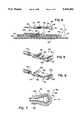
- FIG. 5is a perspective view of a first embodiment of the connector of FIGS. 1 and 3, inverted for clarity, showing the construction of a detent surface for resisting disengagement of the connector;
- FIG. 6is a figure similar to that of FIG. 5 showing a second embodiment of the connector of FIGS. 1 and 3 employing barbs which engage the material of the electrode to prevent disengagement of the connector of FIG. 6.
- FIG. 7is a detailed cross-sectional view along line 7--7 of FIG. 2 of the electrode engaged with the connector showing expansion of a lip of the pocket within a bend of the connector to provide positive engagement of the connector and pocket lip;
- FIG. 8is a planar view of the electrode of FIG. 2 showing deformation of the pocket wall with lateral force on the connector, such deformation serving to retain the connector in engagement with the electrode during such forces.
- FIG. 9is a perspective cutaway view of the electrode of FIG. 2 showing motion of the connector with respect to the electrode with backward force on the lead wire showing the hooking action of the electrical connector resisting disengagement from the electrode;
- FIG. 10is a view similar to that of FIG. 4 showing construction of the pocket of the electrode from a single unfolded sheet of conductive material.
- FIG. 11is a figure similar to that of FIGS. 4 and 10 showing a third embodiment of the invention where the pocket is formed from a fold in the base sheet of the electrode.
- electrodes 20 of the present inventionare arranged for use on a card 22 and held detachably to card 22 by a layer of hydrogel 26.
- the hydrogel 26serves as both an adhesive and an electrolyte and may be any one of a commercially available hydrogel material used in the electrode industry.
- hydrogelmeans generally a high water content gel produced by the coagulation of a colloid with the inclusion of water.
- the hydrogelis selected to be lightly adherent, so as to retain the electrodes 20 on the card 22 or on the skin of the patient during use of the electrode 20, but sufficiently cohesive so that the electrode may be easily removed from the card 22 or skin without any residue of hydrogel 26 remaining on either.
- the conductivity of the hydrogel 26is controlled by the addition of a nontoxic salt capable of ionization, such as sodium chloride, potassium chloride, sodium sulfate and others.
- the thickness of the hydrogel 26is from approximately 5 to 50 mils and preferably from 25 to 30 mils, and preferably the volume resistivity of the hydrogel 26 should range from approximately 3 ⁇ 10 4 ohms-cm to approximately 4.5 ⁇ 10 4 ohms-cm.
- the preferable material of the hydrogel 26is a 40% polyvinyl alcohol, however, other gel materials such as Karaya agar gum, alginates and the like could be used.
- Commercially available hydrogelsare Lectec MP3000 and Medtronics Promeon.
- the hydrogel 26is applied to a "skin side" of a circular base sheet 24 of the electrode.
- the circular base sheet 24is flexible and electrically conductive and may be constructed of a polyvinyl chloride film incorporating finely ground carbon particles, as is well understood in the art.
- Other means of producing conductive, flexible sheets, such as the deposition of a conductive layer on a non-conductive but flexible substratecould also be used.
- the conductive sheetis approximately 4 mils thick and has sufficient carbon to provide it with a surface resistance of 100 ohms-cm.
- electrochemically active material 28is applied to a portion of the skin side of the circular base sheet 24 beneath the hydrogel 26.
- the electrochemically active materialis a combination of silver and silver chloride such as is well known in the art for improving the electrical characteristics of medical electrodes.
- the area of the skin side of the base sheet 24 over which the electrochemically active material 28 is applieddepends on the particular use of the electrode. For stimulating electrodes subject to high polarizing currents, the entire skin side of the base sheet 24 may be coated with the electrochemically active material 28. For short term monitoring purposes, only a small area of the skin side of the base sheet is coated with electrochemically active material 28. This small area may be centered within the base sheet 24 or offset on the base sheet 24.
- the electrochemical material 28may be applied to the base sheet 24 in a number of ways well known in the art, including by a printing process or the pressing of silver and silver chloride onto the surface of the base sheet 24 or by plating or evaporating a layer of silver onto the base sheet and then reacting the silver with chlorine to produce the necessary silver chloride.
- a tab 30formed of a strip of the same conductive material as comprises the circular base sheet 24.
- the tab 30may also be coated with a surface metal layer. The material of the tab 30 is folded along its length to produce a folded edge 32 and the tab 30 is laid with this folded edge positioned diametrically along the circular base sheet 24.
- annular retaining sheet 34having a central aperture 36 and a circumference substantially equal to that of the circular base sheet 24, is applied over the left and right opposing sides of the tab 30 (as viewed orientationally in FIG. 3) to sandwich the tab 30 between the lead side of the circular base sheet 24 and a lower surface of the annular retaining sheet 34.
- the lower surface of the annular retaining sheet 34is coated with a pressure-sensitive adhesive to bond to the upper side of the tab 30 and importantly to bond the annular retaining sheet 34 to the portions of the lead side of the circular base sheet 24 exposed on either side of the tab 30.
- the tab 30 and the central aperture 36are positioned so as to expose the folded edge 32 of the tab 30 but so that the annular retaining sheet 34 covers all other edges of the tab 30 creating a pocket 38 and pressing the tab 30 against the circular base sheet 24 to provide good electrical contact between the tab 30 and the base sheet 24.
- the material of the annular retaining sheet 34need not be conductive and in the preferred embodiment is a thin, printable, non-conductive polymer sheet.
- This pocket 38receives connector 40 inserted along the plane of the circular base sheet 24 to provide electrical contact between the electrode 20 and that connector.
- the folded edge 32 of the tab 30serves to create a raised lip on the pocket 38 guiding insertion of this connector.
- the aperture 36 of the annular retaining sheet 34is sized so that the lip of the pocket formed by the folded edge 32 is substantially larger than the connector to permit insertion of the connector without the need for precise location of the connector with respect to the pocket 38.
- the connector 40 for use with the electrode 20 of the present inventionincludes a hook 42 formed, in the preferred embodiment, of a flat strip of phosphor-bronze plated with gold.
- the connector 40has a generally straight shank portion 44 attached at its first end soldered to an exposed conductor 48 of a monitoring lead 46.
- an insulator 50such as a heat shrinkable tubing or a molded covering.
- the second end of the shank 44forms a bend 52 to produce a bill 54 of the hook 42, the bill 54 returning substantially along the same direction as the shank 44 to create a gap between the shank 44 and the bill 54 substantially equal to the thickness of the tab 30.
- the free end of the bill 54may be received within the pocket 38 formed by the tab 30 and the circular base sheet 24 with the shank 44 lying on the upper surface of the tab 30 and the monitoring lead 46, as covered by insulator 50, lying generally on top of the annular retaining sheet 34 and away from the patient's skin by virtue of the central location of the pocket 38.
- the aperture 36 of the annular retaining sheet 34is sized so that a sufficient portion of the tab 30 is exposed so that significant electrical conduction may be had both between the shank 44 and the tab 30, and between the bill 54 and the tab 30.
- the insertion of the bill 54 into the pocket 38produces a wiping action, removing surface oxidation from the bill and insuring good conduction of low voltages between the electrode 20 and the monitoring lead 46.
- the action of the annular retaining sheet 34 holding the tab 30 against the lead side of the circular base sheet 24preserves the low profile of the electrode 20 and connector 40 when the two are connected.
- the connector 40may be plated with nickel or gold or other conductive materials.
- the bill 54 of the hook 42may include a dimple 56 extending from the bill 54 toward the shank 44 creating between the dimple 56 and the shank 44, a detent surface spaced from the shank 44 by less than the thickness of the tab 30. Accordingly, when the bill 54 is inserted in the pocket 38, (not shown in FIG. 5), the detent surface presses against the tab 30 causing outward flexure of the bill 54 with respect to the shank 44 and causing a clamping of the tab 30 in the hook 42. This clamping improves electrical contact between the connector 40 and the electrode 20 and also helps the connector 40 resist from becoming dislodged from the tab 30 and electrode 20.
- barbs 58extending into the pocket 38 from the hook 42, and opposed on either side the hook 42 along the axis of the lip 32, are pointed from the bill 54 toward the shank 44 and canted towards the bend 52.
- the barbs 58allow insertion of the bill 54 into the pocket 38 with relatively little resistance but then prevent disengagement of the bill 54 from the pocket 38, in the manner of a barb on a fishhook, and prevent the connector 40 from being removed from the electrode 20 without destruction of the tab 30 and considerable force.
- the connector 40 of FIG. 6would be used in situations where considerable activity of the patient would be expected.
- the bend 52 of the hook 42creates a cylindrical volume of slightly greater diameter than the average spacing between the bill 54 and the shank 44.
- This cylindrical volumepermits expansion of the folded end 32 of the tab 30 into this volume once the connector 40 is fully engaged with the electrode 20.
- the expansion of the folded edge 32 of the tab 30is caused by the natural resilience of the material of the tab 30 and creates a "snap" effect providing tactile feedback indicating that a connection had been made. This expansion of the folded edge 32 also serves to retain the connector 40 on the tab 30.
- the electrode 20is normally placed on the patient so that the dominant force on the monitoring lead 46 is along the insertion axis 62 generally lying along the axis of the shank 44 from the first to second end.
- Force along the insertion axis 62in the insertion direction in which the bill 54 is placed within the pocket 38, serves generally to tighten the connection between the connector 40 and the electrode 20 compressing the bend 52 of the connector 40 against the folded edge 32 of the tab 30.
- the connector 40will attempt to shift within the pocket 38 so that the axis of the shank 44 attempts to align with the new perturbation force 60.
- the connector 40will pivot about dimple 56 or one of the barbs 58 and the edge of bend 52 will deform the folded edge 32.
- the deformation of the folded edge 32further retains the connector 40 against slippage.
- the use of the retaining sheet 34 to attach the tab 30 to the electrode 20otherwise allows the connector 40 considerable freedom in rotating to accommodate forces placed on the monitoring leads 46.
- the force along the insertion axis 62 opposite the direction of insertion, rather than causing the connector 40 to disconnect from the electrode 20produces a camming action raising the first end of the shank 44 and forcing the bend 52 downward against the circular base sheet 24 resulting in an upward motion of the dimple 56 or barbs 58 against the lower surface of the tab 30 further resisting disengagement of the connector 40.
- the upward force of the bill 54is largely centered within the electrode 20 and distributed over its adhesive area resisting any tendency of the electrode 20 to peel away from the skin of the patient.
- the central location of the central aperture 36likewise causes the perturbing forces 60 discussed with respect to FIG. 8 to be distributed over a broad adhesive area resisting the tendency of the electrode 20 to peel away from the skin as may occur in electrodes where the attachment is near one edge of the electrodes adhesive surface.
- the tab 30may be formed from an unfolded sheet of conductive material similar to that of circular base sheet 24, laminated, as before, between the annular retaining sheet 34 and the circular base sheet 24.
- the "snap" action or locating ridge of the folded edge 32 of FIG. 4is not present.
- the low profile of the electrode 20is preserved and the manufacturing process simplified.
- the hydrogel 26may be located only on the portion of the skin side of the circular base sheet 24 over which the electrochemically active material 28 is placed. Outside of this area, an adhesive 70, having no conductive properties but having other desirable characteristics such as a stronger adhesive action, may be used. In this situation where separate adhesive 70 is employed, the hydrogel 26 may be replaced with a conventional electrolyte held in a foam pad or the like.
- conductivity between the tab 30 and the conductive base sheet 24may be ensured by forming the tab 30 from a fold made in the material of the circular base sheet 24.
- the tab 30need not be a separate piece of material but may be formed integrally with circular base sheet 24.
Landscapes
- Health & Medical Sciences (AREA)
- Life Sciences & Earth Sciences (AREA)
- Public Health (AREA)
- Engineering & Computer Science (AREA)
- Biomedical Technology (AREA)
- Veterinary Medicine (AREA)
- Animal Behavior & Ethology (AREA)
- General Health & Medical Sciences (AREA)
- Pathology (AREA)
- Physics & Mathematics (AREA)
- Biophysics (AREA)
- Heart & Thoracic Surgery (AREA)
- Medical Informatics (AREA)
- Molecular Biology (AREA)
- Surgery (AREA)
- Radiology & Medical Imaging (AREA)
- Nuclear Medicine, Radiotherapy & Molecular Imaging (AREA)
- Electrotherapy Devices (AREA)
Abstract
Description
Claims (11)
Priority Applications (1)
| Application Number | Priority Date | Filing Date | Title |
|---|---|---|---|
| US08/007,446US5431166A (en) | 1993-01-22 | 1993-01-22 | Low profile medical electrode |
Applications Claiming Priority (1)
| Application Number | Priority Date | Filing Date | Title |
|---|---|---|---|
| US08/007,446US5431166A (en) | 1993-01-22 | 1993-01-22 | Low profile medical electrode |
Publications (1)
| Publication Number | Publication Date |
|---|---|
| US5431166Atrue US5431166A (en) | 1995-07-11 |
Family
ID=21726204
Family Applications (1)
| Application Number | Title | Priority Date | Filing Date |
|---|---|---|---|
| US08/007,446Expired - LifetimeUS5431166A (en) | 1993-01-22 | 1993-01-22 | Low profile medical electrode |
Country Status (1)
| Country | Link |
|---|---|
| US (1) | US5431166A (en) |
Cited By (24)
| Publication number | Priority date | Publication date | Assignee | Title |
|---|---|---|---|---|
| US5571165A (en)* | 1995-12-08 | 1996-11-05 | Ferrari; R. Keith | X-ray transmissive transcutaneous stimulating electrode |
| US5733324A (en)* | 1995-12-08 | 1998-03-31 | Ferrari; R. Keith | X-ray transmissive transcutaneous stimulating electrode |
| US5824033A (en)* | 1995-12-08 | 1998-10-20 | Ludlow Corporation | Multifunction electrode |
| US6280463B1 (en) | 1998-08-26 | 2001-08-28 | Zmd Corporation | Reducing skin damage in use of medical electrodes |
| US6600957B2 (en) | 2001-06-28 | 2003-07-29 | The Ludlow Company Lp | High-energy disposable medical stimulation electrode |
| EP1541190A1 (en)* | 2003-12-09 | 2005-06-15 | Ambu A/S | Electromedical electrode with a detachable cable connector |
| US20080046051A1 (en)* | 2006-08-21 | 2008-02-21 | Skubitz Sean P | Novel features for routing conductors in medical electrical lead electrode assemblies |
| US20080046050A1 (en)* | 2006-08-21 | 2008-02-21 | Skubitz Sean P | Novel medical electrode mounting |
| US20080046049A1 (en)* | 2006-08-21 | 2008-02-21 | Skubitz Sean P | Novel assembly methods for medical electrical leads |
| US20120143033A1 (en)* | 2010-12-01 | 2012-06-07 | Tiegs Mark D | Center ridge ecg monitoring electrode |
| US20130030511A1 (en)* | 2000-09-18 | 2013-01-31 | Cameron Health, Inc. | Subcutaneous Electrode with Improved Contact Shape for Transthoracic Conduction |
| US8690611B2 (en) | 2007-12-11 | 2014-04-08 | Covidien Lp | ECG electrode connector |
| US8706217B2 (en) | 2000-09-18 | 2014-04-22 | Cameron Health | Cardioverter-defibrillator having a focused shocking area and orientation thereof |
| USD737979S1 (en) | 2008-12-09 | 2015-09-01 | Covidien Lp | ECG electrode connector |
| US9138589B2 (en) | 2001-11-21 | 2015-09-22 | Cameron Health, Inc. | Apparatus and method for identifying atrial arrhythmia by far-field sensing |
| US9144683B2 (en) | 2000-09-18 | 2015-09-29 | Cameron Health, Inc. | Post-shock treatment in a subcutaneous device |
| US9408547B2 (en) | 2011-07-22 | 2016-08-09 | Covidien Lp | ECG electrode connector |
| US9408546B2 (en) | 2013-03-15 | 2016-08-09 | Covidien Lp | Radiolucent ECG electrode system |
| USD771818S1 (en) | 2013-03-15 | 2016-11-15 | Covidien Lp | ECG electrode connector |
| US9693701B2 (en) | 2013-03-15 | 2017-07-04 | Covidien Lp | Electrode connector design to aid in correct placement |
| US20190104995A1 (en)* | 2017-10-06 | 2019-04-11 | Medtronic Xomed, Inc. | Pledget stimulation and recording electrode assemblies |
| JP2019162376A (en)* | 2018-03-20 | 2019-09-26 | 株式会社東芝 | Electrode and manufacturing method for electrode |
| CN111839532A (en)* | 2020-07-14 | 2020-10-30 | 天津大学 | A flexible epidermal electrochemical biosensor based on conductive hydrogel |
| WO2021210592A1 (en)* | 2020-04-14 | 2021-10-21 | 株式会社アイ・メデックス | Bioelectrode that can be worn for a long period of time |
Citations (15)
| Publication number | Priority date | Publication date | Assignee | Title |
|---|---|---|---|---|
| US2943628A (en)* | 1957-02-27 | 1960-07-05 | William L Howell | Electrode assembly |
| US3085577A (en)* | 1961-06-12 | 1963-04-16 | Vector Mfg Company Inc | Body electrode |
| US3606881A (en)* | 1970-02-20 | 1971-09-21 | Riley D Woodson | Conductive rubber electrode |
| US3741219A (en)* | 1971-11-24 | 1973-06-26 | R Sessions | Grounding place or electrode for electromedical equipment |
| US3828766A (en)* | 1972-08-14 | 1974-08-13 | Jet Medical Prod Inc | Disposable medical electrode |
| US3998215A (en)* | 1968-12-18 | 1976-12-21 | Minnesota Mining And Manufacturing Company | Bio-medical electrode conductive gel pads |
| US4063352A (en)* | 1976-07-16 | 1977-12-20 | M I Systems, Inc. | Method of making electrode package |
| US4094822A (en)* | 1974-12-26 | 1978-06-13 | Kater John A R | Bio-event electrode material |
| US4166453A (en)* | 1977-01-21 | 1979-09-04 | Cardio Technology Limited | Body electrodes |
| US4522211A (en)* | 1979-12-06 | 1985-06-11 | C. R. Bard, Inc. | Medical electrode construction |
| US4570637A (en)* | 1983-10-20 | 1986-02-18 | Andover Medical Incorporated | Electrode |
| US4679563A (en)* | 1984-10-08 | 1987-07-14 | Nitto Electric Industrial Co., Ltd. | Biomedical electrode |
| US5133356A (en)* | 1991-04-16 | 1992-07-28 | Minnesota Mining And Manufacturing Company | Biomedical electrode having centrally-positioned tab construction |
| US5168875A (en)* | 1991-04-11 | 1992-12-08 | Staodyn, Inc. | Elongated strip electrode arrangement and method |
| US5215087A (en)* | 1988-09-22 | 1993-06-01 | Minnesota Mining And Manufacturing Company | Biomedical electrode construction |
- 1993
- 1993-01-22USUS08/007,446patent/US5431166A/ennot_activeExpired - Lifetime
Patent Citations (15)
| Publication number | Priority date | Publication date | Assignee | Title |
|---|---|---|---|---|
| US2943628A (en)* | 1957-02-27 | 1960-07-05 | William L Howell | Electrode assembly |
| US3085577A (en)* | 1961-06-12 | 1963-04-16 | Vector Mfg Company Inc | Body electrode |
| US3998215A (en)* | 1968-12-18 | 1976-12-21 | Minnesota Mining And Manufacturing Company | Bio-medical electrode conductive gel pads |
| US3606881A (en)* | 1970-02-20 | 1971-09-21 | Riley D Woodson | Conductive rubber electrode |
| US3741219A (en)* | 1971-11-24 | 1973-06-26 | R Sessions | Grounding place or electrode for electromedical equipment |
| US3828766A (en)* | 1972-08-14 | 1974-08-13 | Jet Medical Prod Inc | Disposable medical electrode |
| US4094822A (en)* | 1974-12-26 | 1978-06-13 | Kater John A R | Bio-event electrode material |
| US4063352A (en)* | 1976-07-16 | 1977-12-20 | M I Systems, Inc. | Method of making electrode package |
| US4166453A (en)* | 1977-01-21 | 1979-09-04 | Cardio Technology Limited | Body electrodes |
| US4522211A (en)* | 1979-12-06 | 1985-06-11 | C. R. Bard, Inc. | Medical electrode construction |
| US4570637A (en)* | 1983-10-20 | 1986-02-18 | Andover Medical Incorporated | Electrode |
| US4679563A (en)* | 1984-10-08 | 1987-07-14 | Nitto Electric Industrial Co., Ltd. | Biomedical electrode |
| US5215087A (en)* | 1988-09-22 | 1993-06-01 | Minnesota Mining And Manufacturing Company | Biomedical electrode construction |
| US5168875A (en)* | 1991-04-11 | 1992-12-08 | Staodyn, Inc. | Elongated strip electrode arrangement and method |
| US5133356A (en)* | 1991-04-16 | 1992-07-28 | Minnesota Mining And Manufacturing Company | Biomedical electrode having centrally-positioned tab construction |
Cited By (42)
| Publication number | Priority date | Publication date | Assignee | Title |
|---|---|---|---|---|
| US5571165A (en)* | 1995-12-08 | 1996-11-05 | Ferrari; R. Keith | X-ray transmissive transcutaneous stimulating electrode |
| US5733324A (en)* | 1995-12-08 | 1998-03-31 | Ferrari; R. Keith | X-ray transmissive transcutaneous stimulating electrode |
| US5824033A (en)* | 1995-12-08 | 1998-10-20 | Ludlow Corporation | Multifunction electrode |
| US6280463B1 (en) | 1998-08-26 | 2001-08-28 | Zmd Corporation | Reducing skin damage in use of medical electrodes |
| US6453205B1 (en) | 1998-08-26 | 2002-09-17 | Michael R. Dupelle | Reducing skin damage in use of medical electrodes |
| US9144683B2 (en) | 2000-09-18 | 2015-09-29 | Cameron Health, Inc. | Post-shock treatment in a subcutaneous device |
| US20130030511A1 (en)* | 2000-09-18 | 2013-01-31 | Cameron Health, Inc. | Subcutaneous Electrode with Improved Contact Shape for Transthoracic Conduction |
| US8706217B2 (en) | 2000-09-18 | 2014-04-22 | Cameron Health | Cardioverter-defibrillator having a focused shocking area and orientation thereof |
| US8660668B2 (en)* | 2000-09-18 | 2014-02-25 | Cameron Health, Inc. | Lead fastener |
| US6600957B2 (en) | 2001-06-28 | 2003-07-29 | The Ludlow Company Lp | High-energy disposable medical stimulation electrode |
| US9993653B2 (en) | 2001-11-21 | 2018-06-12 | Cameron Health, Inc. | Apparatus and method for identifying atrial arrhythmia by far-field sensing |
| US9522283B2 (en) | 2001-11-21 | 2016-12-20 | Cameron Health Inc. | Apparatus and method for identifying atrial arrhythmia by far-field sensing |
| US9138589B2 (en) | 2001-11-21 | 2015-09-22 | Cameron Health, Inc. | Apparatus and method for identifying atrial arrhythmia by far-field sensing |
| EP1541190A1 (en)* | 2003-12-09 | 2005-06-15 | Ambu A/S | Electromedical electrode with a detachable cable connector |
| US7738966B2 (en) | 2006-08-21 | 2010-06-15 | Medtronic, Inc. | Features for routing conductors in medical electrical lead electrode assemblies |
| US7742824B2 (en) | 2006-08-21 | 2010-06-22 | Medtronic, Inc. | Medical electrode mounting |
| US8326434B2 (en) | 2006-08-21 | 2012-12-04 | Medtronic, Inc. | Medical electrode mounting |
| US20100325869A1 (en)* | 2006-08-21 | 2010-12-30 | Medtronic, Inc. | Novel assembly methods for medical electrical leads |
| US8489169B2 (en) | 2006-08-21 | 2013-07-16 | Medtronic, Inc. | Assembly methods for medical electrical leads |
| US8634893B2 (en) | 2006-08-21 | 2014-01-21 | Medtronic, Inc. | Features for routing conductors in medical electrical lead electrode assemblies |
| US20100228329A1 (en)* | 2006-08-21 | 2010-09-09 | Medtronic, Inc. | Novel medical electrode mounting |
| US20080046051A1 (en)* | 2006-08-21 | 2008-02-21 | Skubitz Sean P | Novel features for routing conductors in medical electrical lead electrode assemblies |
| US7765011B2 (en) | 2006-08-21 | 2010-07-27 | Medtronic, Inc. | Assembly methods for medical electrical leads |
| US20080046050A1 (en)* | 2006-08-21 | 2008-02-21 | Skubitz Sean P | Novel medical electrode mounting |
| US20080046049A1 (en)* | 2006-08-21 | 2008-02-21 | Skubitz Sean P | Novel assembly methods for medical electrical leads |
| US8690611B2 (en) | 2007-12-11 | 2014-04-08 | Covidien Lp | ECG electrode connector |
| US9107594B2 (en) | 2007-12-11 | 2015-08-18 | Covidien Lp | ECG electrode connector |
| US8795004B2 (en) | 2007-12-11 | 2014-08-05 | Covidien, LP | ECG electrode connector |
| USD737979S1 (en) | 2008-12-09 | 2015-09-01 | Covidien Lp | ECG electrode connector |
| US20120143033A1 (en)* | 2010-12-01 | 2012-06-07 | Tiegs Mark D | Center ridge ecg monitoring electrode |
| US9737226B2 (en) | 2011-07-22 | 2017-08-22 | Covidien Lp | ECG electrode connector |
| US9408547B2 (en) | 2011-07-22 | 2016-08-09 | Covidien Lp | ECG electrode connector |
| US9814404B2 (en) | 2013-03-15 | 2017-11-14 | Covidien Lp | Radiolucent ECG electrode system |
| US9693701B2 (en) | 2013-03-15 | 2017-07-04 | Covidien Lp | Electrode connector design to aid in correct placement |
| USD771818S1 (en) | 2013-03-15 | 2016-11-15 | Covidien Lp | ECG electrode connector |
| US9408546B2 (en) | 2013-03-15 | 2016-08-09 | Covidien Lp | Radiolucent ECG electrode system |
| US20190104995A1 (en)* | 2017-10-06 | 2019-04-11 | Medtronic Xomed, Inc. | Pledget stimulation and recording electrode assemblies |
| US11672487B2 (en)* | 2017-10-06 | 2023-06-13 | Medtronic Xomed, Inc. | Pledget stimulation and recording electrode assemblies |
| JP2019162376A (en)* | 2018-03-20 | 2019-09-26 | 株式会社東芝 | Electrode and manufacturing method for electrode |
| WO2021210592A1 (en)* | 2020-04-14 | 2021-10-21 | 株式会社アイ・メデックス | Bioelectrode that can be worn for a long period of time |
| CN115515493A (en)* | 2020-04-14 | 2022-12-23 | 日商爱医疗电子股份有限公司 | Long-term wearable bioelectrodes |
| CN111839532A (en)* | 2020-07-14 | 2020-10-30 | 天津大学 | A flexible epidermal electrochemical biosensor based on conductive hydrogel |
Similar Documents
| Publication | Publication Date | Title |
|---|---|---|
| US5431166A (en) | Low profile medical electrode | |
| US6076002A (en) | Method of manufacturing a disposable electrode | |
| US4522211A (en) | Medical electrode construction | |
| US4365634A (en) | Medical electrode construction | |
| US3977392A (en) | Medical electrode | |
| US11806151B2 (en) | Patient electrode connectors for electrocardiograph monitoring system | |
| US5921925A (en) | Biomedical electrode having a disposable electrode and a reusable leadwire adapter that interfaces with a standard leadwire connector | |
| US4617935A (en) | Medical electrode | |
| US4653503A (en) | Physiological electrodes for use with magnetic connector | |
| US4852571A (en) | Disposable biopotential electrode | |
| AU644916B2 (en) | Medical electrode assembly | |
| US4077398A (en) | Diagnostic electrode assembly | |
| US3901218A (en) | Disposable electrode | |
| US5626135A (en) | Medical electrode | |
| US4393584A (en) | Method of manufacture of electrode construction | |
| EP1284644B1 (en) | An electrode for establishing electrical contact with the skin | |
| EP0767692B1 (en) | Vented electrode | |
| US3972329A (en) | Body electrode for electro-medical use | |
| US4401356A (en) | Electrical terminal | |
| US20130066412A1 (en) | Electrode assembly with magnetic connection | |
| GB1567962A (en) | Electrical connector for medical electrodes | |
| US4832036A (en) | Medical electrode | |
| US20040072475A1 (en) | Electrode connector | |
| US5209679A (en) | Adaptive medical electrode connector with male stud | |
| EP1541190A1 (en) | Electromedical electrode with a detachable cable connector |
Legal Events
| Date | Code | Title | Description |
|---|---|---|---|
| AS | Assignment | Owner name:CLASSIC MEDICAL PRODUCTS, INC., WISCONSIN Free format text:ASSIGNMENT OF ASSIGNORS INTEREST.;ASSIGNOR:MACUR, ROBERT A.;REEL/FRAME:006471/0902 Effective date:19930121 | |
| AS | Assignment | Owner name:LUDLOW CORPORATION, NEW HAMPSHIRE Free format text:MERGER OF CLASSIC MEDICAL PRODUCTS, INC. INTO CLASSIC MEDICAL GROUP, INC., AND MERGER OF CLASSIC MEDICAL GROUP, INC. INTO LUDLOW CORPORATION. (CERTIFIED TRUE COPIES OF CERTIFICATES OF MERGER ISSUED BY MINNESOTA SECRETARY OF STATE ENCLOSED.);ASSIGNOR:CLASSIC MEDICAL PRODUCTS, INC.;REEL/FRAME:007299/0103 Effective date:19940304 | |
| STCF | Information on status: patent grant | Free format text:PATENTED CASE | |
| FEPP | Fee payment procedure | Free format text:PAYOR NUMBER ASSIGNED (ORIGINAL EVENT CODE: ASPN); ENTITY STATUS OF PATENT OWNER: LARGE ENTITY | |
| FEPP | Fee payment procedure | Free format text:PAT HLDR NO LONGER CLAIMS SMALL ENT STAT AS SMALL BUSINESS (ORIGINAL EVENT CODE: LSM2); ENTITY STATUS OF PATENT OWNER: LARGE ENTITY | |
| FPAY | Fee payment | Year of fee payment:4 | |
| FPAY | Fee payment | Year of fee payment:8 | |
| FPAY | Fee payment | Year of fee payment:12 |