US5431113A - Equipment and process for molten alloy treatment of hazardous liquids and slurries - Google Patents
Equipment and process for molten alloy treatment of hazardous liquids and slurriesDownload PDFInfo
- Publication number
- US5431113A US5431113AUS08/324,693US32469394AUS5431113AUS 5431113 AUS5431113 AUS 5431113AUS 32469394 AUS32469394 AUS 32469394AUS 5431113 AUS5431113 AUS 5431113A
- Authority
- US
- United States
- Prior art keywords
- slurries
- molten alloy
- reactor
- equipment
- hazardous liquids
- Prior art date
- Legal status (The legal status is an assumption and is not a legal conclusion. Google has not performed a legal analysis and makes no representation as to the accuracy of the status listed.)
- Expired - Lifetime
Links
Images


Classifications
- C—CHEMISTRY; METALLURGY
- C10—PETROLEUM, GAS OR COKE INDUSTRIES; TECHNICAL GASES CONTAINING CARBON MONOXIDE; FUELS; LUBRICANTS; PEAT
- C10K—PURIFYING OR MODIFYING THE CHEMICAL COMPOSITION OF COMBUSTIBLE GASES CONTAINING CARBON MONOXIDE
- C10K1/00—Purifying combustible gases containing carbon monoxide
- C10K1/08—Purifying combustible gases containing carbon monoxide by washing with liquids; Reviving the used wash liquors
- C10K1/10—Purifying combustible gases containing carbon monoxide by washing with liquids; Reviving the used wash liquors with aqueous liquids
- C—CHEMISTRY; METALLURGY
- C10—PETROLEUM, GAS OR COKE INDUSTRIES; TECHNICAL GASES CONTAINING CARBON MONOXIDE; FUELS; LUBRICANTS; PEAT
- C10J—PRODUCTION OF PRODUCER GAS, WATER-GAS, SYNTHESIS GAS FROM SOLID CARBONACEOUS MATERIAL, OR MIXTURES CONTAINING THESE GASES; CARBURETTING AIR OR OTHER GASES
- C10J3/00—Production of combustible gases containing carbon monoxide from solid carbonaceous fuels
- C10J3/57—Gasification using molten salts or metals
- C—CHEMISTRY; METALLURGY
- C02—TREATMENT OF WATER, WASTE WATER, SEWAGE, OR SLUDGE
- C02F—TREATMENT OF WATER, WASTE WATER, SEWAGE, OR SLUDGE
- C02F11/00—Treatment of sludge; Devices therefor
- C02F11/10—Treatment of sludge; Devices therefor by pyrolysis
Definitions
- the present inventiondiffers significantly in having a unique under-the-surface diffuser designed to maximize contact and use the high specific gravity of the molten alloy and a baffle to eject solids from the alloy surface.
- the inventioncomprises one or more ceramic diffusers designed to be mechanically submerged in the molten alloy with a liquid feed line going through the diffuser and exiting into a smooth or corrugated bottom face.
- the faceis sloped upward to achieve maximum contact with the molten alloy to achieve total degradation of the hazardous liquid to carbon, hydrogen, nitrogen, and contact with solids to remove various metal ions, where present.
- the metallic ionswill react to remain in the molten alloy.
- Anionssuch as bromine, chlorine, etc. will form salts with components of the alloy composition.
- the alloyis composed of aluminum, iron, copper, calcium, and zinc with amounts of each component as follows:
- the aluminummay be the cheapest commercial grade containing a great number of metallic impurities or may be aluminum such as found at junk yards.
- the inventioncomprises process and equipment for pyrolyzing a waste stream by pumping the hazardous liquid waste through a floating or partially submerged ceramic diffuser into a molten alloy composition.
- the alloy compositionmay be varied to suit a particular liquid waste stream.
- the alloy compositionnormally aluminum, copper, calcium, iron and zinc, is held in a molten state at 650°-850° C.
- Induction heatingis a preferred embodiment of a heater for the alloy pyrolysis reactor but fossil fuel heating is satisfactory.
- Pyrolysisis carried out in the near absence of atmospheric oxygen. Inert gas or carbon dioxide may be used for purging the system of atmospheric oxygen.
- Ceramic diffusers with a liquid feed line going through the ceramic diffusersmay float or be held with diffuser faces submerged in the molten alloy. In a preferred embodiment the face of each diffuser is sloped upward to direct flotation of solids to the alloy surface and to assure maximum contact of the feed and initial degradation products with the molten alloy.
- Off gas containing mainly hydrogen, water vapor, carbon, nitrogen and/or carbon dioxidemay be subject to additional heat to achieve a temperature of over 450° C. by using an induction heater in the off gas line.
- off gasis scrubbed using an aqueous liquid feed through spray nozzles in a scrubber-separator tank to remove carbon.
- Sludge from the cyclone separatoris filtered through one of a pair of dual filters to remove carbon and allow in-line filter cleaning.
- Aqueous discharge from the filtersmay go through a cooler prior to recycling to spray nozzles for continuous scrubbing. Water make up or purge necessary will depend upon operating conditions. With temperatures of circulating liquid sufficiently high very little purge other than vapor to the atmosphere will be required. Normal controls and relief valves are used in the process.
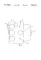
- FIG. 1schematically shows the process.
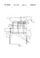
- FIG. 2shows a top view of the reactor in a first embodiment.
- FIG. 3shows a side view of the reactor of FIG. 2.
- FIG. 4shows an end view of reactor of FIG. 2 indicating relative location of major elements.
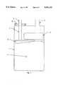
- FIG. 5shows an end view of a second embodiment of the reactor.
- FIG. 6shows a top view of the second embodiment of the reactor.
- FIG. 7shows a feed line with a screw conveyor to feed into the reactor.
- FIG. 1we've shown the process.
- the main unit of the processis the reactor 1 and embodiments will be described in detail under FIG. 2, 3, 4, 5, and 6.
- a molten alloyis heated and held molten either by induction heating or by fossil fuel heating.
- Molten alloy temperaturemay be varied widely and be sufficient for decomposition and reaction necessary for metal extraction, organic degradation to elements, melting glass etc. but a temperature of about 850° C. is preferred. At this temperature carbon dioxide would not be held by the calcium normally present in the molten alloy but chlorides would be held thus preventing loss through volatile aluminum chlorides.
- slurry type wastesmay be pumped by pump 34 through valve 2.
- Wastesmay be fed from bin 6 using a motor driven star feeder type valve 8 or may be fed through feed bin 41 using a screw conveyor as shown in FIG. 7.
- Many slurry type wasteswill. completely disintegrate when forced under the molten alloy level in reactor 1 and carbon, hydrogen, nitrogen, carbon dioxide, water vapor will exit the reactor in the off gas.
- some sludge type wastessuch as refinery tailings all the lighter hydrocarbons will decompose, most of the heavy metals will be extracted, and all the water will be expelled. However some land-fillable solids will remain. These exit the reactor through line 7 to catch tank, 13.
- Feed line 3may be bolted directly to the top of the reactor 1 or go through packing gland 12 to allow adjustment in diffuser height.
- inert gas or carbon dioxide through valve 35is used to purge air out of the system, including the reactor (1) and feed line (3). Reaction in an oxygen free environment is desirable.
- the reactoris equipped with a filling nozzle 10 for addition of metal to the alloy as needed.
- the filling nozzlemay be hingedly closed with a high temperature glass to allow visual observation of the unit in operation.
- Off-gas from the unitmay go through an induction heater 14 designed to make certain that the off-gas temperature exceeds 450° C. to eliminate any traces of pathogens.
- Off-gas line 4leads to scrubber 20.
- Scrubber 20is equipped with a relief valve 16 which may be a simple flapper type valve balanced to open at less than 0.1 pound per square inch. Water fed through spray nozzles 18 in scrubber 20 serve both to cool and to scrub off gas in the unit.
- Scrubber 20may be equipped with a demister 21. Loose woven wire demisters work well. Other type scrubber-separators could be used equally well. Water, carbon, and dissolved salts, if any, discharge through valve 24. Valve 24 would normally be open with automatic valve 30 being operatived automatically by level controller 22 to hold a low aqueous level in scrubber 20. The scrubbed off-gas exits to the atmosphere through line 38.
- Aqueous effluent from the separator 20goes through pump 26 which may be a centrifugal ordiaphragm pump and through dual filters 28. Dual filters allow manual cleaning of one filter while the other continuous is operation.
- the clean aqueous filtrate from filter 28recycles through a cooler 32, which may be an air or water cooler to spray nozzles 18 to cool and scrub the incoming off-gas.
- FIG. 2we've shown a top view of one preferred embodiment: of reactor 1. Visible from the top are feed lines 3, that we've shown as three in number but could be a minimum of one depending upon unit size, off-gas line 4, sight glass and metal fill nozzle 10, power ram drive 11 and solids discharge line 7. Shown dotted is a top view of ram 9 and feed diffuser shoes 5. Feed diffuser shoes 5 are shown in more detail in FIG. 4. Ram drive 11 may be hydraulic or motor driven.
- FIG. 3we show a side of a preferred embodiment of the reactor.
- a minimum level relative to diffuser shoes 5 for molten alloy 17is shown in a wavy line.
- Slurries or near slurries or flowable solidsmay be fed from feed bin 6 through star feeder type valves 8 through feed tubes 3, alternatively pumpable sludges or slurries may be fed using a diaphragm pump 34 through valves 39 into feed tubes 3 and down through diffuser shoes 5 into molten alloy 17.
- Feed tubes 3may either go through packing glands 12 or be bolted to top flanges, as shown in FIG. 4.
- Ram 13 with drive gear 11serves to push solids that accumulate on the surface of alloy 17 into a discharge line 7.
- FIG. 4we've shown an end view of reactor 1 indicating shape of diffuser 5 and shape and relative location of ram 13. With bottom face of diffuser 5 sloping as indicated any solids will float upward below the molten alloy 17 surface to be in the path of ram 13 for discharge. Experience has shown that molten alloy 17 will penetrate many solids and effectively remove metals even when the solid is not totally disintegrated. In this view we've shown feed tube 3 bolted to the top at flange 19, stud bolts would be preferred.
- FIG. 5we've shown a second embodiment of the reactor 1 wherein treated solid 31 float to the surface 33 of molten metal 17 and are directed by sloping baffle 21 to overflow into container 25.
- Baffle 21may be ceramic fused around adjustable supports 29.
- a ceramic projection 23prevents molten metal overflow into container 25.
- Other figures in FIG. 5are as previously described.
- FIG. 6we've shown a top view of FIG. 5 indicating the elongated shape of discharge container 25.
- Flange 19is large enough to permit entry of diffuser shoe 5.
- the sight glass and filling port 10is located to permit addition of metal to the alloy.
- FIG. 7we've shown one feed tube 3 wherein a screw conveyor 37 driven by motor 40 allows continuously feeding solids or near solid sludges from bin 41 to below the surface of diffuser 5.
Landscapes
- Chemical & Material Sciences (AREA)
- Engineering & Computer Science (AREA)
- Combustion & Propulsion (AREA)
- Oil, Petroleum & Natural Gas (AREA)
- Organic Chemistry (AREA)
- Chemical Kinetics & Catalysis (AREA)
- General Chemical & Material Sciences (AREA)
- Processing Of Solid Wastes (AREA)
Abstract
Description
Claims (14)
Priority Applications (1)
| Application Number | Priority Date | Filing Date | Title |
|---|---|---|---|
| US08/324,693US5431113A (en) | 1990-05-16 | 1994-10-18 | Equipment and process for molten alloy treatment of hazardous liquids and slurries |
Applications Claiming Priority (5)
| Application Number | Priority Date | Filing Date | Title |
|---|---|---|---|
| US07/524,278US5000101A (en) | 1989-05-25 | 1990-05-16 | Hazardous waste reclamation process |
| US66975691A | 1991-03-15 | 1991-03-15 | |
| US07/982,450US5271341A (en) | 1990-05-16 | 1992-11-27 | Equipment and process for medical waste disintegration and reclamation |
| US08/103,122US5359947A (en) | 1990-05-16 | 1993-08-09 | Equipment and process for waste pyrolysis and off gas oxidative treatment |
| US08/324,693US5431113A (en) | 1990-05-16 | 1994-10-18 | Equipment and process for molten alloy treatment of hazardous liquids and slurries |
Related Parent Applications (1)
| Application Number | Title | Priority Date | Filing Date |
|---|---|---|---|
| US08/103,122Continuation-In-PartUS5359947A (en) | 1990-05-16 | 1993-08-09 | Equipment and process for waste pyrolysis and off gas oxidative treatment |
Publications (1)
| Publication Number | Publication Date |
|---|---|
| US5431113Atrue US5431113A (en) | 1995-07-11 |
Family
ID=27493321
Family Applications (1)
| Application Number | Title | Priority Date | Filing Date |
|---|---|---|---|
| US08/324,693Expired - LifetimeUS5431113A (en) | 1990-05-16 | 1994-10-18 | Equipment and process for molten alloy treatment of hazardous liquids and slurries |
Country Status (1)
| Country | Link |
|---|---|
| US (1) | US5431113A (en) |
Cited By (12)
| Publication number | Priority date | Publication date | Assignee | Title |
|---|---|---|---|---|
| US5832845A (en)* | 1990-05-16 | 1998-11-10 | Wagner; Anthony S. | Equipment for molecular decomposition of hazardous wastes using a molten media reactor |
| US6069290A (en)* | 1990-05-16 | 2000-05-30 | Clean Technologies International Corporation | Waste treatment process and reactant metal alloy |
| WO2000056407A1 (en)* | 1999-03-23 | 2000-09-28 | Clean Technologies International Corporation | High temperature molten metal reactor and waste treatment method |
| US6669755B2 (en) | 2002-06-04 | 2003-12-30 | Clean Technologies International Corporation | Apparatus and method for treating containerized feed materials in a liquid reactant metal |
| US20040064010A1 (en)* | 2002-09-26 | 2004-04-01 | Wagner Anthony S. | Liquid metal reactor and method for treating materials in a liquid metal reactor |
| US20060008406A1 (en)* | 2004-07-09 | 2006-01-12 | Clean Technologies International Corporation | Method and apparatus for preparing a collection surface for use in producing carbon nanostructures |
| US20060008403A1 (en)* | 2004-07-09 | 2006-01-12 | Clean Technologies International Corporation | Reactant liquid system for facilitating the production of carbon nanostructures |
| US20060008405A1 (en)* | 2004-07-09 | 2006-01-12 | Wagner Anthony S | Method and apparatus for producing carbon nanostructures |
| US20060034746A1 (en)* | 2004-08-16 | 2006-02-16 | Wagner Anthony S | Method and apparatus for producing fine carbon particles |
| US7901653B2 (en) | 2004-07-09 | 2011-03-08 | Clean Technology International Corporation | Spherical carbon nanostructure and method for producing spherical carbon nanostructures |
| EP2948530A4 (en)* | 2013-01-23 | 2016-10-12 | How Kiap Gueh | Gasifier for generation of synthesis gas |
| US20210134473A1 (en)* | 2011-06-02 | 2021-05-06 | Australian Nuclear Science And Technology Organisation | Filling Container And Method For Storing Hazardous Waste Material |
Citations (1)
| Publication number | Priority date | Publication date | Assignee | Title |
|---|---|---|---|---|
| US5301620A (en)* | 1993-04-01 | 1994-04-12 | Molten Metal Technology, Inc. | Reactor and method for disassociating waste |
- 1994
- 1994-10-18USUS08/324,693patent/US5431113A/ennot_activeExpired - Lifetime
Patent Citations (1)
| Publication number | Priority date | Publication date | Assignee | Title |
|---|---|---|---|---|
| US5301620A (en)* | 1993-04-01 | 1994-04-12 | Molten Metal Technology, Inc. | Reactor and method for disassociating waste |
Cited By (34)
| Publication number | Priority date | Publication date | Assignee | Title |
|---|---|---|---|---|
| US6069290A (en)* | 1990-05-16 | 2000-05-30 | Clean Technologies International Corporation | Waste treatment process and reactant metal alloy |
| US5832845A (en)* | 1990-05-16 | 1998-11-10 | Wagner; Anthony S. | Equipment for molecular decomposition of hazardous wastes using a molten media reactor |
| WO2000056407A1 (en)* | 1999-03-23 | 2000-09-28 | Clean Technologies International Corporation | High temperature molten metal reactor and waste treatment method |
| US6669755B2 (en) | 2002-06-04 | 2003-12-30 | Clean Technologies International Corporation | Apparatus and method for treating containerized feed materials in a liquid reactant metal |
| US20040124569A1 (en)* | 2002-06-04 | 2004-07-01 | Wagner Anthony S. | Apparatus and method for treating containerized feed materials in a liquid reactant metal |
| US6929676B2 (en) | 2002-06-04 | 2005-08-16 | Clean Technologies International Corporation | Apparatus and method for treating containerized feed materials in a liquid reactant metal |
| US7365237B2 (en) | 2002-09-26 | 2008-04-29 | Clean Technologies International Corporation | Liquid metal reactor and method for treating materials in a liquid metal reactor |
| US20040064010A1 (en)* | 2002-09-26 | 2004-04-01 | Wagner Anthony S. | Liquid metal reactor and method for treating materials in a liquid metal reactor |
| US20080226511A1 (en)* | 2002-09-26 | 2008-09-18 | Wagner Anthony S | Liquid metal reactor |
| US7550128B2 (en)* | 2004-07-09 | 2009-06-23 | Clean Technologies International Corporation | Method and apparatus for producing carbon nanostructures |
| US7815886B2 (en) | 2004-07-09 | 2010-10-19 | Clean Technology International Corporation | Reactant liquid system for facilitating the production of carbon nanostructures |
| US9133033B2 (en)* | 2004-07-09 | 2015-09-15 | Clean Technology International Corp. | Reactant liquid system for facilitating the production of carbon nanostructures |
| US20080050303A1 (en)* | 2004-07-09 | 2008-02-28 | Wagner Anthony S | Reactant Liquid System For Facilitating The Production Of Carbon Nanostructures |
| US20060008405A1 (en)* | 2004-07-09 | 2006-01-12 | Wagner Anthony S | Method and apparatus for producing carbon nanostructures |
| US20060008403A1 (en)* | 2004-07-09 | 2006-01-12 | Clean Technologies International Corporation | Reactant liquid system for facilitating the production of carbon nanostructures |
| US20090155160A1 (en)* | 2004-07-09 | 2009-06-18 | Wagner Anthony S | Method and Apparatus for Producing Carbon Nanostructures |
| US20060008406A1 (en)* | 2004-07-09 | 2006-01-12 | Clean Technologies International Corporation | Method and apparatus for preparing a collection surface for use in producing carbon nanostructures |
| US7563426B2 (en)* | 2004-07-09 | 2009-07-21 | Clean Technologies International Corporation | Method and apparatus for preparing a collection surface for use in producing carbon nanostructures |
| US8263037B2 (en) | 2004-07-09 | 2012-09-11 | Clean Technology International Corporation | Spherical carbon nanostructure and method for producing spherical carbon nanostructures |
| US20110189076A1 (en)* | 2004-07-09 | 2011-08-04 | Wagner Anthony S | Spherical carbon nanostructure and method for producing spherical carbon nanostructures |
| US20100172817A1 (en)* | 2004-07-09 | 2010-07-08 | Wagner Anthony S | Method And Apparatus For Preparing A Collection Surface For Use In Producing Carbon Nanostructures |
| US7814846B2 (en) | 2004-07-09 | 2010-10-19 | Clean Technology International Corporation | Method and apparatus for preparing a collection area for use in producing carbon nanostructures |
| US7922993B2 (en) | 2004-07-09 | 2011-04-12 | Clean Technology International Corporation | Spherical carbon nanostructure and method for producing spherical carbon nanostructures |
| US7815885B2 (en) | 2004-07-09 | 2010-10-19 | Clean Technology International Corporation | Method and apparatus for producing carbon nanostructures |
| US20110033366A1 (en)* | 2004-07-09 | 2011-02-10 | Wagner Anthony S | Reactant liquid system for facilitating the production of carbon nanostructures |
| US7901653B2 (en) | 2004-07-09 | 2011-03-08 | Clean Technology International Corporation | Spherical carbon nanostructure and method for producing spherical carbon nanostructures |
| US20060034746A1 (en)* | 2004-08-16 | 2006-02-16 | Wagner Anthony S | Method and apparatus for producing fine carbon particles |
| US20100003185A1 (en)* | 2004-08-16 | 2010-01-07 | Wagner Anthony S | Method and apparatus for producing fine carbon particles |
| US8197787B2 (en) | 2004-08-16 | 2012-06-12 | Clean Technology International Corporation | Method and apparatus for producing fine carbon particles |
| US7587985B2 (en)* | 2004-08-16 | 2009-09-15 | Clean Technology International Corporation | Method and apparatus for producing fine carbon particles |
| WO2006093530A3 (en)* | 2004-08-16 | 2006-12-21 | Clean Technologies Int Corp | Method and apparatus for producing fine carbon particles |
| US20210134473A1 (en)* | 2011-06-02 | 2021-05-06 | Australian Nuclear Science And Technology Organisation | Filling Container And Method For Storing Hazardous Waste Material |
| US12094619B2 (en)* | 2011-06-02 | 2024-09-17 | Australian Nuclear Science and Technology Organisation. | Filling container and method for storing hazardous waste material |
| EP2948530A4 (en)* | 2013-01-23 | 2016-10-12 | How Kiap Gueh | Gasifier for generation of synthesis gas |
Similar Documents
| Publication | Publication Date | Title |
|---|---|---|
| US5431113A (en) | Equipment and process for molten alloy treatment of hazardous liquids and slurries | |
| US5271341A (en) | Equipment and process for medical waste disintegration and reclamation | |
| US5000101A (en) | Hazardous waste reclamation process | |
| US4412889A (en) | Pyrolysis reaction apparatus | |
| US7473348B2 (en) | Diesel oil from residues by catalytic depolymerization with energy input from a pump-agitator system | |
| US6172275B1 (en) | Method and apparatus for pyrolytically decomposing waste plastic | |
| KR20210055076A (en) | Pyrolysis plant | |
| US4469661A (en) | Destruction of polychlorinated biphenyls and other hazardous halogenated hydrocarbons | |
| US5461991A (en) | Equipment and process for molten alloy pyrolysis of hazardous liquid waste | |
| HUT54915A (en) | Apparatus and method for utilizing used oil | |
| WO1996023734A1 (en) | Method for treating halogenated hydrocarbons prior to hydrothermal oxidation | |
| US6042718A (en) | Process for removing water from a water-containing crude oil | |
| US5553558A (en) | Equipment and process for surface treatment of hazardous solids and slurries with molten alloy | |
| US4445910A (en) | Gas generating system and process | |
| US5832845A (en) | Equipment for molecular decomposition of hazardous wastes using a molten media reactor | |
| US4018588A (en) | Method and apparatus for handling slag handling | |
| RU2358016C2 (en) | Procedure for collection and treatment of reactive gases from installation for producing liquid metals and corresponding installation for dust removal | |
| US6227126B1 (en) | Molten metal reactor and treatment method for treating gaseous materials and materials which include volatile components | |
| CA2261600C (en) | A method and apparatus for removing gaseous elementary mercury from a gas | |
| US4254089A (en) | Product recovery from alkali metal wastes | |
| US4200617A (en) | Product recovery from alkali metal wastes | |
| US4127399A (en) | Method of making granulated slag | |
| US3840468A (en) | Method for separating water from emulsions containing oil and device for same | |
| FI104712B (en) | Process for oxidation of wastewater containing organic substances | |
| JP2016089079A (en) | Waste plastic oiling equipment |
Legal Events
| Date | Code | Title | Description |
|---|---|---|---|
| STCF | Information on status: patent grant | Free format text:PATENTED CASE | |
| AS | Assignment | Owner name:CLEAN TECHNOLOGIES INTERNATIONAL CORPORATION, TEXA Free format text:ASSIGNMENT OF ASSIGNORS INTEREST;ASSIGNOR:WAGNER, ANTHONY S.;REEL/FRAME:009328/0759 Effective date:19980720 | |
| FEPP | Fee payment procedure | Free format text:PAYOR NUMBER ASSIGNED (ORIGINAL EVENT CODE: ASPN); ENTITY STATUS OF PATENT OWNER: SMALL ENTITY | |
| FPAY | Fee payment | Year of fee payment:4 | |
| REMI | Maintenance fee reminder mailed | ||
| FPAY | Fee payment | Year of fee payment:8 | |
| SULP | Surcharge for late payment | Year of fee payment:7 | |
| REMI | Maintenance fee reminder mailed | ||
| FPAY | Fee payment | Year of fee payment:12 | |
| SULP | Surcharge for late payment | Year of fee payment:11 | |
| AS | Assignment | Owner name:CLEAN TECHNOLOGY INTERNATIONAL CORPORATION, TEXAS Free format text:CORRECTIVE ASSIGNMENT TO CORRECT THE NAME OF THE ASSIGNEE SHOWN IN THE ORIGINAL ASSIGNMENT PREVIOUSLY RECORDED ON REEL 009328 FRAME 0759;ASSIGNOR:WAGNER, ANTHONY S.;REEL/FRAME:023373/0245 Effective date:19980720 | |
| AS | Assignment | Owner name:WAGNER, SHARON KAY, CALIFORNIA Free format text:ASSIGNMENT OF ASSIGNORS INTEREST;ASSIGNOR:WAGNER, ANTHONY S.;REEL/FRAME:033541/0110 Effective date:20140812 |