US5430666A - Automated method and apparatus for calibration of laser scanning in a selective laser sintering apparatus - Google Patents
Automated method and apparatus for calibration of laser scanning in a selective laser sintering apparatusDownload PDFInfo
- Publication number
- US5430666A US5430666AUS07/992,559US99255992AUS5430666AUS 5430666 AUS5430666 AUS 5430666AUS 99255992 AUS99255992 AUS 99255992AUS 5430666 AUS5430666 AUS 5430666A
- Authority
- US
- United States
- Prior art keywords
- sheet
- cell
- laser
- values
- error
- Prior art date
- Legal status (The legal status is an assumption and is not a legal conclusion. Google has not performed a legal analysis and makes no representation as to the accuracy of the status listed.)
- Expired - Fee Related
Links
- 238000000034methodMethods0.000titleclaimsabstractdescription102
- 238000000110selective laser sinteringMethods0.000titledescription19
- 238000012937correctionMethods0.000claimsabstractdescription44
- 230000013011matingEffects0.000claims1
- 239000000843powderSubstances0.000description33
- 230000001419dependent effectEffects0.000description12
- 238000011960computer-aided designMethods0.000description9
- 230000006870functionEffects0.000description7
- 238000004364calculation methodMethods0.000description6
- 238000005516engineering processMethods0.000description6
- 238000005259measurementMethods0.000description6
- 230000000873masking effectEffects0.000description5
- 230000000694effectsEffects0.000description4
- 238000004519manufacturing processMethods0.000description4
- 239000011347resinSubstances0.000description4
- 229920005989resinPolymers0.000description4
- 239000000654additiveSubstances0.000description3
- 230000000996additive effectEffects0.000description3
- 238000007796conventional methodMethods0.000description3
- 239000000463materialSubstances0.000description3
- 238000012986modificationMethods0.000description3
- 230000004048modificationEffects0.000description3
- 230000036962time dependentEffects0.000description3
- 238000012546transferMethods0.000description3
- 238000013519translationMethods0.000description3
- 239000013598vectorSubstances0.000description3
- 241000226585Antennaria plantaginifoliaSpecies0.000description2
- 238000006073displacement reactionMethods0.000description2
- 238000009826distributionMethods0.000description2
- 238000003754machiningMethods0.000description2
- 238000012423maintenanceMethods0.000description2
- 238000010606normalizationMethods0.000description2
- 230000000737periodic effectEffects0.000description2
- 239000004033plasticSubstances0.000description2
- 229920003023plasticPolymers0.000description2
- 238000005245sinteringMethods0.000description2
- 238000003860storageMethods0.000description2
- 229920002799BoPETPolymers0.000description1
- 239000005041Mylar™Substances0.000description1
- 229910052782aluminiumInorganic materials0.000description1
- XAGFODPZIPBFFR-UHFFFAOYSA-NaluminiumChemical compound[Al]XAGFODPZIPBFFR-UHFFFAOYSA-N0.000description1
- 238000013459approachMethods0.000description1
- 239000000919ceramicSubstances0.000description1
- 238000012512characterization methodMethods0.000description1
- 238000004891communicationMethods0.000description1
- 230000008021depositionEffects0.000description1
- 238000009795derivationMethods0.000description1
- 238000013461designMethods0.000description1
- 238000010586diagramMethods0.000description1
- 238000010191image analysisMethods0.000description1
- 238000011835investigationMethods0.000description1
- 239000003550markerSubstances0.000description1
- 239000011159matrix materialSubstances0.000description1
- 229910052751metalInorganic materials0.000description1
- 239000002184metalSubstances0.000description1
- 150000002739metalsChemical class0.000description1
- 238000012544monitoring processMethods0.000description1
- 230000036961partial effectEffects0.000description1
- 238000002360preparation methodMethods0.000description1
- 238000000926separation methodMethods0.000description1
- 238000011179visual inspectionMethods0.000description1
- 239000001993waxSubstances0.000description1
Images


Classifications
- G—PHYSICS
- G05—CONTROLLING; REGULATING
- G05B—CONTROL OR REGULATING SYSTEMS IN GENERAL; FUNCTIONAL ELEMENTS OF SUCH SYSTEMS; MONITORING OR TESTING ARRANGEMENTS FOR SUCH SYSTEMS OR ELEMENTS
- G05B19/00—Programme-control systems
- G05B19/02—Programme-control systems electric
- G05B19/18—Numerical control [NC], i.e. automatically operating machines, in particular machine tools, e.g. in a manufacturing environment, so as to execute positioning, movement or co-ordinated operations by means of programme data in numerical form
- G05B19/401—Numerical control [NC], i.e. automatically operating machines, in particular machine tools, e.g. in a manufacturing environment, so as to execute positioning, movement or co-ordinated operations by means of programme data in numerical form characterised by control arrangements for measuring, e.g. calibration and initialisation, measuring workpiece for machining purposes
- G05B19/4015—Numerical control [NC], i.e. automatically operating machines, in particular machine tools, e.g. in a manufacturing environment, so as to execute positioning, movement or co-ordinated operations by means of programme data in numerical form characterised by control arrangements for measuring, e.g. calibration and initialisation, measuring workpiece for machining purposes going to a reference at the beginning of machine cycle, e.g. for calibration
- B—PERFORMING OPERATIONS; TRANSPORTING
- B29—WORKING OF PLASTICS; WORKING OF SUBSTANCES IN A PLASTIC STATE IN GENERAL
- B29C—SHAPING OR JOINING OF PLASTICS; SHAPING OF MATERIAL IN A PLASTIC STATE, NOT OTHERWISE PROVIDED FOR; AFTER-TREATMENT OF THE SHAPED PRODUCTS, e.g. REPAIRING
- B29C64/00—Additive manufacturing, i.e. manufacturing of three-dimensional [3D] objects by additive deposition, additive agglomeration or additive layering, e.g. by 3D printing, stereolithography or selective laser sintering
- B29C64/10—Processes of additive manufacturing
- B29C64/141—Processes of additive manufacturing using only solid materials
- B29C64/153—Processes of additive manufacturing using only solid materials using layers of powder being selectively joined, e.g. by selective laser sintering or melting
- B—PERFORMING OPERATIONS; TRANSPORTING
- B33—ADDITIVE MANUFACTURING TECHNOLOGY
- B33Y—ADDITIVE MANUFACTURING, i.e. MANUFACTURING OF THREE-DIMENSIONAL [3-D] OBJECTS BY ADDITIVE DEPOSITION, ADDITIVE AGGLOMERATION OR ADDITIVE LAYERING, e.g. BY 3-D PRINTING, STEREOLITHOGRAPHY OR SELECTIVE LASER SINTERING
- B33Y10/00—Processes of additive manufacturing
- B—PERFORMING OPERATIONS; TRANSPORTING
- B33—ADDITIVE MANUFACTURING TECHNOLOGY
- B33Y—ADDITIVE MANUFACTURING, i.e. MANUFACTURING OF THREE-DIMENSIONAL [3-D] OBJECTS BY ADDITIVE DEPOSITION, ADDITIVE AGGLOMERATION OR ADDITIVE LAYERING, e.g. BY 3-D PRINTING, STEREOLITHOGRAPHY OR SELECTIVE LASER SINTERING
- B33Y30/00—Apparatus for additive manufacturing; Details thereof or accessories therefor
- Y—GENERAL TAGGING OF NEW TECHNOLOGICAL DEVELOPMENTS; GENERAL TAGGING OF CROSS-SECTIONAL TECHNOLOGIES SPANNING OVER SEVERAL SECTIONS OF THE IPC; TECHNICAL SUBJECTS COVERED BY FORMER USPC CROSS-REFERENCE ART COLLECTIONS [XRACs] AND DIGESTS
- Y02—TECHNOLOGIES OR APPLICATIONS FOR MITIGATION OR ADAPTATION AGAINST CLIMATE CHANGE
- Y02P—CLIMATE CHANGE MITIGATION TECHNOLOGIES IN THE PRODUCTION OR PROCESSING OF GOODS
- Y02P90/00—Enabling technologies with a potential contribution to greenhouse gas [GHG] emissions mitigation
- Y02P90/02—Total factory control, e.g. smart factories, flexible manufacturing systems [FMS] or integrated manufacturing systems [IMS]
Definitions
- This inventionis in the field of laser-based additive processes for fabricating objects, and is more particularly directed to methods of calibrating the laser in the same.
- the scan of the laser across the target surfaceis generally in raster scan fashion, with the laser beam modulated on and off at locations corresponding to the cross-section of the object in that layer; alternatively, the laser may be operated in a vector mode so as to "draw" the object cross-section in the powder layer.
- fused locations within each layeradhere to fused portions of previously fused layers, so that a series of layers processed in this manner results in a finished part.
- Computer control of the scanning of the energy beamthus enables direct transfer of a design in a computer-aided-design (CAD) data base into a physical object.
- CADcomputer-aided-design
- the parts produced by selective laser sinteringmay have shapes and features which are sufficiently complex as to not be capable of fabrication by conventional subtractive processes such as machining. This complexity is enabled by the natural support of overhanging fused portions of the object that is provided by unfused powder remaining in prior layers.
- stereolithographyAnother laser-based process for forming of three-dimensional objects is commonly referred to as stereolithography.
- a directed light beamsuch as a laser operating at ultraviolet wavelengths, is used to cure selected portions of the surface of a vat of photopolymer.
- a first type of erroris geometry-dependent error, which is based upon the angle from the vertical of the laser beam.
- Fundamental plane geometryindicates that the linear displacement of the irradiated location of the target surface is nonlinearly related to the angle of the laser beam from the vertical, and thus is nonlinearly related to angular displacement of the beam.
- conventional scanning of a laser beam across a planeusing a pair of planar mirrors oriented to deflect the beam in two dimensions, will draw an arc with a radius dependent upon the distances of the mirrors from the target plane.
- a second type of imprecisionresults from a mismatch between the resolution of the image field and that of the laser scanning system, in the case where scanning correction is performed as a function of the scanning field. If the number of correction points are defined according to the digital resolution of the scanning system, where the image field is somewhat smaller than that scannable by the scanning system, the number of possible correction locations is reduced from its optimal density.
- a third type of erroris scanner error that is a function of distance on the image plane.
- scanner errorssuch as linearity error and gain scaling error will increase with the length of the vector or line drawn on the image plane.
- Distance-dependent error of this typewill result in vectors drawn on the image line which have dimensional errors that are a function of (e.g., a percentage of) their length, as opposed to an absolute error value.
- These distance-dependent errors and their variation over the image fieldstrongly depend upon the dimensions of each specific scanner, and do not behave according to a theoretical function. As such, accurate correction for distance-dependent error requires empirical characterization of each system.
- a fourth error typecorresponds to time-dependent scanner error and temperature-dependent error. Errors such as gain drift and offset drift are examples of this fourth error type. Physical causes of such drift include slight mirror rotation or optic movements due to vibration, thermal expansion, or bumps to the system, resulting in scanner positioning error. These errors tend to be dependent upon the environment in which the machine is installed, and changes in this environment over time.
- the use of the pinhole plate apparatusis inherently limited in its accuracy. This is because the energy level of a laser beam over its width tends to be quite uniform within its spot, thus making it difficult to distinguish the true center of the laser beam spot relative to locations within the laser beam spot that is some distance away. Considering that the energy level inside of the laser beam is extremely high relative to the energy outside of the beam, the necessary dynamic range of conventional sensors will limit the ability to discern two relatively high energy levels from one another. Furthermore, it has been observed that variations in laser power over time are greater than the difference between the energy at the true center of the spot and the energy within the spot but away from the center. As such, it is contemplated that this conventional approach is quite limited in accurately correcting for scanner error of the above-described types.
- the present inventionmay be implemented into a method for calibrating the scanning in a laser-based apparatus for fabricating a three-dimensional object.
- a first portion of the methodperforms theoretical calculation of the geometric error values in a matrix corresponding to the physical parameters of the scanning system. These theoretical calculations are used to set values for each cell, or region, of the scan field, in combination with a scaling factor to account for differences between the image field and the scan area of the system; these theoretical error values are loaded into the memory of a computer, and comprise an error table for the image field. After the theoretical error table is determined, actual laser data is obtained by using the laser to burn locations in an image sheet placed over the target surface.
- the image sheetis then digitized and stored in the memory of a computer, for use in adjusting the error values, for each cell, based upon the distance between the centroid of the burned spot in the image sheet and the center of the cell. If the computer calculating the updated error table correction factors is different from that controlling the laser, the adjusted error table is loaded into the controlling computer for operation.
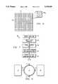
- FIG. 1is a schematic diagram of a selective laser sintering apparatus for producing three-dimensional objects from a powder in layerwise fashion, and into which the present invention is incorporated.
- FIG. 2is an isometric and schematic view of the portion of the apparatus of FIG. 1 which controls the direction of the laser beam to the target surface.
- FIG. 3is a flow chart illustrating the method of the preferred embodiment of the invention.
- FIGS. 4a, 4b and 5are a schematic illustration of the geometry of the laser in FIG. 2 relative to performing theoretical geometric corrections.
- FIG. 6is a representation of the scan field relative to cells in the error table stored in the memory of the controlling computer.
- FIG. 7is a flow chart illustrating the preparation of the system for the automated calibration method of the present invention.
- FIG. 8is a plan view of the floor of the selective laser sintering apparatus, and the placement of tape strips for the marking of the axes in the selective laser sintering system, according to the present invention.
- FIG. 9illustrates, in plan view, the placement of the mounting disk for the linear standard over the part piston in the selective laser sintering system.
- FIG. 10illustrates, in plan view, the linear standard used according to the preferred embodiment of the invention.
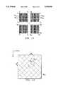
- FIG. 11illustrates in plan view, the results of the scanning of selected cell marks in the linear standard according to the preferred embodiment of the invention.
- FIG. 12illustrates schematically the updating of the correction factors for an error table cell in memory of the computer, according to the present invention.
- the apparatus of FIG. 1includes a chamber 2 (front doors and the top of chamber 2 are not shown in FIG. 1, for purposes of clarity), within which the selective sintering process takes place.
- Target surface 4for purposes of the description herein, refers to the top surface of heat-fusible powder (including portions previously sintered, if present) disposed on part piston 6; the sintered and unsintered powder disposed on part piston 6 will be referred to herein as part bed 7.
- the vertical motion of part piston 6is controlled by motor 8.
- Laser 10provides a beam which is reflected by galvanometer-controlled mirrors (only single mirror 47 is shown in FIG. 1 for clarity), in the manner described in the U.S. Patents referred to hereinabove and as shown in FIG. 2.
- FIG. 2illustrates laser 10 and its control system 12.
- the components of the laser systemare shown in FIG. 2 as integrated within laser head 10.
- Laser head 10thus includes such conventional control elements as described in the above-referenced U.S. Pat. No. 4,863,538, for example a safety shutter, a front mirror assembly, and focusing elements such as diverging and converging lenses.
- the type of laser 10 usedis dependent upon many factors, and in particular upon the type of powder that is to be sintered.
- a preferred laseris a Synrad Model C48-115 CO 2 laser.
- Laser 10is preferably controllable to be modulated on and off; while on, laser 10 produces laser beam 5 which travels generally along the path shown by the arrows in FIG. 2.
- Computer 40 and scanning control system 12are also included for controlling the direction of the laser beam as it impinges target surface 4.
- computer 40includes a microprocessor for controlling laser 10 according to CAD/CAM data by which the dimensions of the part to be produced is defined.
- a conventional personal computer workstationsuch as a model 486-33 manufactured and sold by Mobius Computer Corporation, based on an 80486DX-33 microprocessor as manufactured and sold by Intel Corporation, is suitable for use as computer 40 in the preferred embodiment.
- Scanning system 12includes prism 44 for redirecting the path of travel of the laser beam; the number of prisms 44 necessary for directing the laser beam to the proper location depends, of course, upon the physical layout of the apparatus. Alternatively, as is well known in the art, one or more fixed mirrors can be used in place of prism 44 for directing laser beam 5 from laser 10 to the scanning system 12, depending upon the particular layout of the equipment.
- Scanning system 12further includes a pair of mirrors 46, 47 which are driven by respective galvanometers 48, 49. In this example, mirror 46 controls scanning of the laser in the x-direction (i.e., the fast axis) and mirror 47 controls scanning of the laser in the y-direction.
- Galvanometers 48, 49are coupled to their respective mirrors 46, 47 to selectively orient the mirrors 46, 47 and control the aim of laser beam 5, and as such are mounted perpendicularly to one another so that mirrors 46, 47 are mounted nominally at a right angle relative to one another.
- Function generator driver 42controls the movement of galvanometers 48 and 49 and in turn the aim of laser beam 5 within target surface 4, in conjunction with on and off modulation of laser 10 as controlled by computer 40.
- Driver 42is coupled to computer 40, so that the CAD/CAM data within computer 40 can be realized in the directional control of the laser beam via mirrors 46, 47.
- alternative scanning systemsmay be used in place of scanning system 12, including such apparatus as acousto-optic scanners, rotating polygonal mirrors, and resonant mirror scanners.
- the apparatus of FIG. 1supplies powder to chamber 2 via powder cylinder 14; powder is placed into chamber 2 by the upward partial motion of powder cylinder 14 provided by motor 16.
- Roller 18preferably provided with a scraper to prevent buildup, said scraper not shown in FIG. 1 for clarity spreads the powder within the chamber by translation from powder cylinder 14 toward and across target surface 4 at the surface of part bed 7 above part piston 6, in the manner described in the above-referenced PCT Publication 88/02677 and U.S. Pat. No. 5,252,264.
- target surface 4(whether a prior layer is disposed thereat or not) is preferably below the floor of chamber 2 by a small amount, for example 5 mils, to define the thickness of the powder layer to be processed. It is preferable, for smooth and thorough distribution of the powder, that the amount of powder provided by powder cylinder 14 be greater than that which can be accepted by part cylinder 6, so that some excess powder will result from the motion of roller 18 across target surface 4; this may be accomplished by the upward motion of powder piston 14 by a greater amount than the distance below the floor of chamber 2 that target surface 4 is set at (e.g., 10 mils versus 5 mils). It is also preferable to slave the counter-rotation of roller 18 to the translation of roller 18 within chamber 2, so that the ratio of rotational speed to translation speed is constant.
- laser 10selectively sinters portions of the powder at target surface 4 corresponding to the cross-section of the layer of the part to be produced, in the manner described in the above-referenced U.S. Patents, PCT Publication, and pending applications.
- part piston 6moves downward by an amount corresponding to the thickness of the next layer, awaiting the deposition of the next layer of powder from roller 18 to be added to part bed 7.
- FIG. 3a method of calibrating and normalizing the scan of laser beam 5 across target surface 4 according to the present invention will now be described.
- sources, or types, of errorexist in the system of FIGS. 1 and 2 that affect the faithfulness by which the CAD data base representation of an object is reproduced by the selective laser sintering process.
- error typesit has been observed that geometry-dependent error, correction cell density errors, and distance-dependent error are prevalent in conventional selective laser sintering systems.
- the method of FIG. 3provides an automated way of generating a correction table, specified for each region of target surface 4, and which accounts for these three sources of error.
- the method of FIG. 3is contemplated to be performed by external computer 41, rather than by computer 40 of FIG. 2 which also controls the scanning and operation of laser 10 in the exemplary system.
- Use of such an external computerallows computer 40 to have its computational power optimized for controlling the selective laser sintering system, including the storage and access of an error table corresponding to the image field, and need not be configured to perform the computational operations described hereinbelow.
- the calibration operation described hereinis not contemplated to be performed continuously, but rather will generally be a periodic maintenance operation, considering that the interior of chamber 2 will be accessed to set and lase the linear standards in the manner described below; as such, it is not believed that the use of external computer 41 will present any significant inefficiency to this process.
- computer 40itself may alternatively perform the operations described hereinbelow.
- a conventional personal computer workstationfor example of the Macintosh type manufactured and sold by Apple Computer Inc., will be adequate to serve as external computer 41 for performing the method of FIG. 3, with the results communicated to computer 40 by way of a network, modem port, removable disk, or other conventional technique (as suggested in FIG. 2).
- external computer 40actually control the operation of laser 10 and the remainder of the system, in lieu of computer 40, during the calibration process described hereinbelow.
- the error table resident in the memory of external computer 41may then be loaded into computer 40, and control of the system returned to computer 40.
- the method of FIG. 3begins with process 50, in which the actual measurements of the system being calibrated are provided to external computer 41. These measurements include the actual distance d z from the pivot point of y-dimension mirror 47 to target surface 4, which varies from machine to machine but is generally approximately 26.5 inches. Also input to external computer 41 at this time is the width of the image field to be scanned at target surface 4 (e.g., 12.1875 inches), and the scan area width of the scan area used by computer 40 to create a pattern script file for the control of the laser (e.g., 12.0 inches).
- the external computerUpon receiving these inputs, the external computer operates to produce a theoretical error table in processes 52 and 54.
- the theoretical error table produced by processes 52 and 54is a table of error values, with arguments for the x and y dimensions, according to which the scan-of laser beam 5 is adjusted by computer 40 to account for theoretical geometric errors occurring as the angle of laser beam 5 varies from the vertical. As discussed above, these geometric errors depend upon the location of planar y-dimension mirror 47 from target surface 4 and the distance between planar x-dimension mirror 46 from y-dimension mirror 47. In this type of arrangement, the length of the line segment between the y-dimension mirror and the target surface, taken normal to the target surface, will draw an arc above the target surface as the angle of the beam deviates from the normal.
- FIG. 4aillustrates the drawing of this arc A above target surface 4, rather than a straight line segment parallel to the y-axis as desired.
- laser beam 5is to be directed to point P by operation of mirrors 46, 47 under the control of galvanometers 48, 49, respectively.
- Point Phas the coordinates (X, Y, Z), considering the origin to be at the center of y-dimension mirror 47, at its axis of rotation; as such, the plane of target surface 4 is at a distance Z away from the center of y-dimension mirror 47.
- the angle ⁇ ycorresponds to the angle of laser beam 5 from the vertical in the y-dimension
- the angle ⁇ xcorresponds to the angle of laser beam 5 from the vertical in the x-dimension.
- ethe distance between the center of y-dimension mirror 47 (at its axis of rotation) and the center of x-dimension mirror 46, and according to well-known relationships in the field of laser scanning of a planar surface according to this system, one may determine corrected values of the angle of laser beam 5 from the vertical in order to irradiate point P as follows:
- the focal radius frmay also be found for this system in the conventional manner, as follows:
- these geometric errorsare corrected in processes 52 and 54 by generating a correction table having an array of cells, each cell corresponding to a region of target surface 4 within the image field, and each cell containing correction factors in the x-dimension and in the y-dimension, expressed as scanning units.
- a correction tablehaving an array of cells, each cell corresponding to a region of target surface 4 within the image field, and each cell containing correction factors in the x-dimension and in the y-dimension, expressed as scanning units.
- FIG. 6an example of such a correction table is illustrated schematically. It is to be understood that the correction table illustrated in FIG. 6 is merely a pictorial representation of a look-up table stored in memory of external computer 41 (and, eventually, computer 40), in this embodiment of the invention.
- the theoretical error tableis arranged in an array of cells, each cell corresponding to a portion of the area of the scan field (i.e., a range of x and y positions).
- the use of multiple cellsallows for the present invention to correct for those error types that are continuously varying over the scan field.
- scan field 62corresponds to the scan area over which digital control of laser beam 5 may be effected by computer 40.
- this scan field 62will generally be larger than the actual image field of target surface 4 over laser beam 5 will physically scan, and thus at which the object may be formed; according to the present invention, scaling of scan field 62 to the image field will be performed later, in process 52.
- scan field 62corresponds to an area greater than the portion of target surface 4 at which the article is to be formed (i.e., the image field).
- scan field 62is divided into cells 64, each corresponding to a rectangular portion of scan field 62 at a particular position.
- 256 cells 64are illustrated, with sixteen cells 64 on a side of image field 4'; of course, it is contemplated that greater or fewer numbers of cells 64 may be used.
- Each cell 64 of the correction table for scan field 62contains correction factors ⁇ x , ⁇ y for the x-dimension and the y-dimension, respectively. These correction factors are stored and utilized as numbers of scan units n x , n y , respectively; the size of each scan unit corresponds to the size of scan field 62 divided by the number of digital states for the scanner. For example, where scan field 62 is twelve inches on a side and the number of digital states is 2 16 , each scan unit corresponds to 0.1831 mils.
- process 52is first performed, in which a scale factor SF is determined for each cell 64.
- Scale factor 64accounts for the difference in size between scan field 62 and the image field at target surface 4 at which the article is to be produced.
- Each cell 64 jkstores its own scale factor SF jk , according to this embodiment of the invention, so that scaling errors discovered during the calibration may be corrected.
- all scale factors SFare set at the same value, as the compensation for the difference in size between scan field 62 and the image field is linear.
- each SF jkis initially set to the value 0.60 (unitless).
- the number of scan units corresponding to the position of each cell 64 jk and to its correction factors ⁇ x , ⁇ ywill be multiplied by scale factor SF jk for that cell 64 jk , prior to controlling the scan of laser beam 5 accordingly.
- the correction factors ⁇ x , ⁇ y in scan unitsare calculated in the theoretical case in process 54 according to the present invention. This calculation is performed by external computer 41, considering the scaled location of the centroid of each cell 64 jk , the distance z d from target surface 4 to the origin at the rotational axis of mirror 47, and the distance e between mirrors 46, 47, as noted above.
- the correction factors for each cell 64 jkare then calculated, initially in the x-dimension only (as the distance e does not affect the angle ⁇ y , where the y-mirror 47 is closest to target surface 4), by calculating the difference:
- Theoretical error correctionsare also produced in process 54, in both of the x and y dimensions and for each cell, according to the ratio of a projected arc drawn across each cell to the length of the cell.
- the correction ratio for one dimensionmay be calculated by determining the ratio of d 1 /d in the arrangement of FIG. 4b, where d is the ideal linear distance (image field size/total number of cells) in one dimension.
- the angle ⁇ max (n)is the product of the maximum deflection angle (e g., 20°) and the ratio of the cell location n to the total number of cells. Calculation of the distance d 1 is thus rudimentary from elementary plane geometry.
- Each cellhas its ratio d 1 /d calculated for each of its x and y dimensions, and the theoretical error table is adjusted accordingly, in process 54.
- measurement and calibrationbegins with process 56, in which the system is prepared for the placement of a linear standard over target surface 4.
- the linear standard used according to this preferred embodiment of the inventionis a pattern having cells corresponding to cells 64 discussed above, and which can be marked with laser beam 5.
- the method of the present inventionutilizes these markings to adjust the theoretical error table for each cell, and thus to provide finely tuned correction factors for the system.
- Step 51 of process 56begins with the centering of laser beam 5 over target surface 4, prior to the placement of the linear standard thereover, after laser beam 5 has been properly focused.
- This centering operationis performed without powder or any other apparatus over part piston 6;
- FIG. 8illustrates the position of part piston 6 so exposed, adjacent feed pistons 14 on either side thereof.
- Centering of laser beam 5is performed manually, by placing masking tape over the center of part piston 6, measuring the exact center of part piston 6, and operating laser 10 to direct laser beam 5 at its centered position.
- Variation between laser beam 5 and the true center of part piston 6is corrected by conventional adjustment of mirrors 46, 47.
- the lased center pointshould be within 0.2 inches of the true center of part piston 6 in order for the automated process described herein to provide the best results.
- masking tape strips 77are placed closely outside of part piston 6 as horizontal and vertical tangents thereto, so that the x and y axes may be marked by laser beam 5.
- Laser beam 5is then directed to burn line segments in tape strips 77 outside of part piston 6, for example at 15 to 30 Watts. These line segments burned into masking tape strips 77 correspond to the x and y intercepts of the axes at the edges of part piston 6.
- mounting disk 70is placed over part piston 6 in process 55.
- Mounting disk 70is a machined aluminum disk approximately 12 inches in diameter (corresponding to part piston 6), and approximately 2 inches thick. As illustrated in FIG. 9, mounting disk 70 is placed over part piston 6, and rotationally adjusted so that alignment pins 75 are aligned with the y-axis marks in masking tape strips 77. Further, part piston 6 is adjusted so that the surface of mounting disk 70 is substantially flush with the actual part bed (i.e., with the floor of the chamber).
- the linear standardis a flexible sheet 78, for example formed of MYLAR plastic, upon which cell marks 80 are arranged in a manner corresponding to cells 64 of the error table discussed above.
- Cell marks 80are printed by conventional ink in such a manner that the application of laser beam 5 thereto of reasonable power will effect removal of the ink at the irradiated locations.
- sheet 78includes a 65-by-65 array of cell marks 80, each cell mark 80 being an inked square.
- the size of each cell mark 80in this example, is approximately 0.1875 inches on a side (ignoring the space between adjacent cell marks 80); measured in scan units, each cell mark 80 is 1024 (1 k) scan units on a side in this example.
- sheet 78includes alignment holes 85 therethrough, which mate with alignment pins 75 of mounting disk 70.
- sheet 78includes tabs 81 having lines thereupon which indicate the x and y axes; in process 57, sheet 78 is aligned so that the lines of tabs 81 overlie the lines 77' in masking tape strips 77 thereunder. It is preferred that each of the axes have a relatively small error relative to its line 77' as opposed to three of the axes having no error but the fourth having a large error.
- setup of the calibrationis completed by again directing laser beam 5 at the center of part piston 6, after placement of sheet 78.
- the spot burned by laser beam 5should be roughly at the center of the cell mark 80 having x-position 32 and y-position 32 (where the origin is at the upper left-hand corner of the array of cell marks 80.
- the burned location of the cell mark 80is re-inked (e.g., by an ink marker), and setup of the system for automatic calibration is complete.
- each cell 64corresponds to a cell mark 80 on sheet 78.
- Laser 10is operated according to such a prior program, and at such power conditions (e.g., 5 Watts) that it burns away the ink of each cell mark 80 that it irradiates.
- power conditionse.g., 5 Watts
- Other adjustmentsmay be necessary to the system to accomplish process 58, including the operation of the system in air, rather than an inert atmosphere as is usually the case when producing objects.
- FIG. 11illustrates gross scaling error from process 58, for selected cell marks 80 from the extremes of the four quadrants of sheet 78.
- laser spots 81 for each cell mark 80was burned at the corner furthest from the center of sheet 78.
- laser mark 81 1 ,2is located at the upper-left corner of cell mark 80 1 ,2 while laser mark 81 64 ,1 is located at the upper-right corner of cell mark 80 64 ,1.
- process 67is then performed in which the scale factor SF in each cell 64 in the error table is adjusted to account for the gross error.
- all scale factors SFmay be reduced by the same multiplicative constant to account for the gross error; alternatively, only portions of the error table may have its scale factor SF adjusted. It is contemplated that, according to the preferred embodiment of the invention, it is preferable to allow the user flexibility in modifying the gross error at this stage, including the use of visual inspection of sheet 78 to determine if cells 80 are missing spots entirely, or if a region of the sheet has a gross scaling error. After updating the error table in the memory of external computer 41, and downloading the updated error table to computer 40, a new sheet 78 is placed over target surface 4, and process 58 is repeated until the gross error reaches an acceptable level (as determined visually in process 60).
- automated adjustment of the error tablemay be effected.
- the automated adjustmentbegins with scanning of sheet 78 by way of a conventional digital scanner, such as a SILVERSCAN scanner manufactured and sold by La Cie, and using conventional digital scanning software, as process 66 of FIG. 3.
- the size of sheet 78may be such that sheet 78 must be trimmed, and perhaps quartered or otherwise sectioned, in order to fit within the digital scanner. In such a case, the scanning process will, of course, have to account for such sequential entry of scanned data.
- external computer 41Upon completion of process 66, external computer 41 will have a digital representation of each cell mark 80 in its memory.
- each digitized cell mark 80be edited to ensure that such artifacts as scratches or digitization errors are not present. It is therefore preferable to edit each digitized cell mark with a conventional draw program (such as the Adobe Photoshop program available from Adobe Systems) in external computer 41, to ensure that each digitized cell mark 80 is stored as a square, and so that the only mark within the stored cell mark 80 is substantially a circle at the location lased in process 58.
- a conventional draw programsuch as the Adobe Photoshop program available from Adobe Systems
- Such editingmay also include enlarging too small of a lased dot; such enlarging must be done, of course, in a concentric manner with the dot appearing in cell mark 80.
- process 69is then performed by external computer 41, in which it updates the correction factors ⁇ x , ⁇ y , expressed in scan units, for each cell 64 of the error table.
- This updatingis performed by external computer 41 automatically, for each stored digitized cell mark 80, by calculating the centroid of the digitized laser mark 81 and comparing this centroid to the center of cell mark 80.
- FIG. 12illustrates cell mark 80 j ,k with its true center TC indicated.
- Cell mark 80 j ,khas laser mark 81 j ,k therein, but offset due to error in the scanning system.
- Laser mark 81 j ,khas a centroid CT which, due to this error, is offset from true center TC; if no error were present, centroid CT would be coincident with true center TC.
- external computer 41analyzes each digitized cell mark 80 and calculates the difference between its true center TC and the centroid CT of the laser mark 81 therein, measured in scan units. It is contemplated that such image analysis programs and techniques are well within the ability of one of ordinary skill in the art having reference to this specification and drawings.
- external computer 41adjusts the error table in its memory for the cell 64 corresponding to the cell mark 80 so analyzed. In the example of FIG. 12, the correction factors for cell 64 j ,k will be updated as follows:
- ⁇ x0 and ⁇ x1are the prior and updated values of the x-dimension correction factor, respectively, where ⁇ y0 and ⁇ y1 are the prior and updated values of the y-dimension correction factor, respectively, and where the adjustments dx, dy are illustrated in FIG. 12.
- This correctionis performed for all cells 64 in the error table in process 69, and the error table updated. During such correction, it is preferred that data be compiled relative to the measured and analyzed error from the last iteration of processes 66, 69, to determine if the degree of the correction is within predetermined bounds.
- Decision 83analyzes one or more metrics of the corrected error against certain limits, such that the process may be repeated if the extent of the error is not sufficiently small. For example, in decision 83, external computer 41 may compare the largest error found in process 69 against a limit, and also the mean of all corrected errors against another limit, to determine if the error determined in process 69 is sufficiently small that the accuracy of the system is acceptable.
- external computer 41may consider a metric of how much the worst, or mean, error has changed from a prior iteration to determine if the error correction has reached a maximum point. In either case, if the error correction in process 69 is of such degree that an additional iteration is necessary, the process is repeated from process 58, where a new linear standard sheet 78 is again lased according to the newly updated error table downloaded into computer 40. Since the gross error is expected to be acceptable for this repeat of process 58, the linear standard sheet 78 is again scanned into the memory of external computer 41, and analyzed in process 69 to again update the error table. The automated correction process continues until the accuracy of the error table is maximized.
- mounting disk 70may then be removed from the system, so that the system is ready for use in producing articles.
- an automated calibration systemwhich is capable of highly accurate scanning, despite the presence of geometry-based, distance-based and correction cell density-based errors.
- the calibration system according to the present inventionconsiders the actual results of the laser scanning over the entire scan field, and adjusts the error for each small region of the scan field independently, based on actual results. Accordingly, even where the error is a continuous function of position over the scan field, the calibration method and system according to the present invention accurately accounts for such error according to actual measurements.
- the measurement of the actual laser scanis accomplished according to the present invention in such a manner that does not require the use of expensive photodetection technology, such technology being especially expensive for infrared wavelengths such as used in the selective laser sintering process. Difficulties with measuring the location and intensity of laser spots are avoided, since the laser marks utilized according to the present invention are consistent with the substantially uniform energy distribution across conventional laser beams.
- historical data from the calibration of the systemmay be stored in its memory.
- Such historical data, properly analyzed,can provide information regarding the drift of the scanning system over time, or due to excursions or cycles in temperature or machine environment. This information can be used to schedule periodic maintenance of the system, particularly by identifying drift in a parameter that is leading toward system failure.
- the accuracy and stability of the scanning systemmay be tracked over time according to this method, and compared against other systems.
Landscapes
- Engineering & Computer Science (AREA)
- Chemical & Material Sciences (AREA)
- Materials Engineering (AREA)
- Manufacturing & Machinery (AREA)
- Physics & Mathematics (AREA)
- Optics & Photonics (AREA)
- Mechanical Engineering (AREA)
- Human Computer Interaction (AREA)
- General Physics & Mathematics (AREA)
- Automation & Control Theory (AREA)
- Laser Beam Processing (AREA)
Abstract
Description
θ.sub.y =tan.sup.-1 [Y/Z]
θ.sub.x =tan.sup.-1 [x/((Z.sup.2 +Y.sup.2).sup.1/2 +e)]
fr=[((Z.sup.2 +Y.sup.2).sup.1/2 +e).sup.2 +X.sup.2 ].sup.1/2
tan.sup.-1 [x/((Z.sup.2 +Y.sup.2).sup.-1/2)+e)]-tan.sup.-1 [x/((Z.sup.2 +Y.sup.2).sup.-1/2)]
Δ.sub.x1 =Δ.sub.x0 -dx
Δ.sub.y1 =Δ.sub.y0 +dy
Claims (17)
Priority Applications (3)
| Application Number | Priority Date | Filing Date | Title |
|---|---|---|---|
| US07/992,559US5430666A (en) | 1992-12-18 | 1992-12-18 | Automated method and apparatus for calibration of laser scanning in a selective laser sintering apparatus |
| AU47985/93AAU4798593A (en) | 1992-12-18 | 1993-08-02 | Automated scanning calibration for selective laser sintering |
| PCT/US1993/007258WO1994015265A1 (en) | 1992-12-18 | 1993-08-02 | Automated scanning calibration for selective laser sintering |
Applications Claiming Priority (1)
| Application Number | Priority Date | Filing Date | Title |
|---|---|---|---|
| US07/992,559US5430666A (en) | 1992-12-18 | 1992-12-18 | Automated method and apparatus for calibration of laser scanning in a selective laser sintering apparatus |
Publications (1)
| Publication Number | Publication Date |
|---|---|
| US5430666Atrue US5430666A (en) | 1995-07-04 |
Family
ID=25538462
Family Applications (1)
| Application Number | Title | Priority Date | Filing Date |
|---|---|---|---|
| US07/992,559Expired - Fee RelatedUS5430666A (en) | 1992-12-18 | 1992-12-18 | Automated method and apparatus for calibration of laser scanning in a selective laser sintering apparatus |
Country Status (3)
| Country | Link |
|---|---|
| US (1) | US5430666A (en) |
| AU (1) | AU4798593A (en) |
| WO (1) | WO1994015265A1 (en) |
Cited By (88)
| Publication number | Priority date | Publication date | Assignee | Title |
|---|---|---|---|---|
| US5497007A (en)* | 1995-01-27 | 1996-03-05 | Applied Materials, Inc. | Method for automatically establishing a wafer coordinate system |
| WO1996011420A1 (en)* | 1994-10-05 | 1996-04-18 | Synrad, Inc. | Laser scanner |
| US5531093A (en)* | 1995-04-17 | 1996-07-02 | The United States Of America As Represented By The Administrator Of The National Aeronautics And Space Administration | Means for positioning and repositioning scanning instruments |
| US5832415A (en)* | 1994-10-18 | 1998-11-03 | Eos Gmbh Electro Optical Systems | Method and apparatus for calibrating a control apparatus for deflecting a laser beam |
| US5999184A (en)* | 1990-10-30 | 1999-12-07 | 3D Systems, Inc. | Simultaneous multiple layer curing in stereolithography |
| WO2000002293A1 (en)* | 1998-07-07 | 2000-01-13 | Dtm Corporation | Laser power control with stretched initial pulses |
| US6276431B1 (en) | 2000-02-29 | 2001-08-21 | Visteon Global Technologies, Inc. | Method of making a spray formed rapid tool |
| EP1145827A1 (en)* | 2000-02-19 | 2001-10-17 | DaimlerChrysler AG | Apparatus and method for laser sintering a powder |
| US20020164069A1 (en)* | 2001-02-16 | 2002-11-07 | Fuji Photo Film Co., Ltd. | Optical modeling device and exposure unit |
| US20020182782A1 (en)* | 2000-08-17 | 2002-12-05 | Farnworth Warren M. | Stereolithographic methods for fabricating hermetic semiconductor device packages and semiconductor devices including stereolithographically fabricated hermetic packages |
| US20030052105A1 (en)* | 2001-09-10 | 2003-03-20 | Fuji Photo Film Co., Ltd. | Laser sintering apparatus |
| US6621039B2 (en)* | 2000-11-27 | 2003-09-16 | The National University Of Singapore | Method and apparatus for creating a free-form three-dimensional metal part using high-temperature direct laser melting |
| US6628442B1 (en)* | 2000-04-21 | 2003-09-30 | Pixar Animation Studios | Method and apparatus for beam deflection using multiple beam scanning galvanometers |
| US20040036161A1 (en)* | 2000-02-10 | 2004-02-26 | Williams Vernon M. | Heat sinks including nonlinear passageways |
| US20040056378A1 (en)* | 2002-09-25 | 2004-03-25 | Bredt James F. | Three dimensional printing material system and method |
| US6820677B2 (en) | 2002-08-20 | 2004-11-23 | Ford Motor Company | Method of making a spray formed article |
| US20040265413A1 (en)* | 2003-05-23 | 2004-12-30 | Z Corporation | Apparatus and methods for 3D printing |
| US20050047644A1 (en)* | 2003-09-03 | 2005-03-03 | Wong Soon Wei | Rotating prism component inspection system |
| US20050059757A1 (en)* | 2003-08-29 | 2005-03-17 | Z Corporation | Absorbent fillers for three-dimensional printing |
| US20050181315A1 (en)* | 2003-12-31 | 2005-08-18 | University Of Southern California | Method for electrochemically fabricating three-dimensional structures including pseudo-rasterization of data |
| US20050197431A1 (en)* | 2000-04-14 | 2005-09-08 | Z Corporation | Compositions for three-dimensional printing of solid objects |
| US20060072072A1 (en)* | 2004-09-30 | 2006-04-06 | Pixar | Anamorphic recording method and apparatus |
| US20060084265A1 (en)* | 2003-12-31 | 2006-04-20 | University Of Southern California | Method for electrochemically fabricating three-dimensional structures including pseudo-rasterization of data |
| US20060141145A1 (en)* | 1996-12-20 | 2006-06-29 | Z Corporation | Three-dimensional printer |
| US7261542B2 (en) | 2004-03-18 | 2007-08-28 | Desktop Factory, Inc. | Apparatus for three dimensional printing using image layers |
| US7332537B2 (en) | 1996-09-04 | 2008-02-19 | Z Corporation | Three dimensional printing material system and method |
| US20080063867A1 (en)* | 2004-10-19 | 2008-03-13 | Schlienger M E | Method and apparatus associated with anisotropic shrink in sintered ceramic items |
| US20080169204A1 (en)* | 2006-10-25 | 2008-07-17 | Rolls-Royce Plc | Method and apparatus for treating a component of a gas turbine engine |
| EP1950001A1 (en)* | 2007-01-25 | 2008-07-30 | Rolls-Royce plc | Apparatus and method for calibrating a laser deposition system |
| US20080304975A1 (en)* | 2007-06-05 | 2008-12-11 | Rolls-Royce Plc | Method for producing abrasive tips for gas turbine blades |
| US20090020257A1 (en)* | 1998-11-20 | 2009-01-22 | Frasier Donald J | Method and apparatus for production of a cast component |
| WO2009018857A1 (en)* | 2007-08-06 | 2009-02-12 | Stephen Hastings | Method for reactive optical correction of galvano motor scanning heads |
| US20090051935A1 (en)* | 2007-08-23 | 2009-02-26 | Guthrie Cooper | Automatic Geometric Calibration Using Laser Scanning Reflectometry |
| US20090059297A1 (en)* | 2005-02-24 | 2009-03-05 | Fujifilm Corporation | Calibration method for image rendering device and image rendering device |
| US7569273B2 (en) | 2003-05-21 | 2009-08-04 | Z Corporation | Thermoplastic powder material system for appearance models from 3D printing systems |
| US7686995B2 (en) | 1996-12-20 | 2010-03-30 | Z Corporation | Three-dimensional printer |
| US20100150730A1 (en)* | 2008-12-15 | 2010-06-17 | Rolls-Royce Plc | Component having an abrasive layer and a method of applying an abrasive layer on a component |
| US7795349B2 (en) | 1999-11-05 | 2010-09-14 | Z Corporation | Material systems and methods of three-dimensional printing |
| US7828022B2 (en) | 2006-05-26 | 2010-11-09 | Z Corporation | Apparatus and methods for handling materials in a 3-D printer |
| US20110037848A1 (en)* | 2009-08-09 | 2011-02-17 | Michael Christopher Maguire | Method and apparatus for calibrating a projected image manufacturing device |
| US7905951B2 (en) | 2006-12-08 | 2011-03-15 | Z Corporation | Three dimensional printing material system and method using peroxide cure |
| US7968626B2 (en) | 2007-02-22 | 2011-06-28 | Z Corporation | Three dimensional printing material system and method using plasticizer-assisted sintering |
| US8167999B2 (en) | 2007-01-10 | 2012-05-01 | 3D Systems, Inc. | Three-dimensional printing material system with improved color, article performance, and ease of use |
| US8475946B1 (en) | 2007-03-20 | 2013-07-02 | Bowling Green State University | Ceramic article and method of manufacture |
| US8568649B1 (en)* | 2007-03-20 | 2013-10-29 | Bowling Green State University | Three-dimensional printer, ceramic article and method of manufacture |
| US8851151B2 (en) | 1998-11-20 | 2014-10-07 | Rolls-Royce Corporation | Method and apparatus for production of a cast component |
| US9254535B2 (en) | 2014-06-20 | 2016-02-09 | Velo3D, Inc. | Apparatuses, systems and methods for three-dimensional printing |
| EP3159080A1 (en)* | 2015-10-19 | 2017-04-26 | Siemens Aktiengesellschaft | Method of adjusting an additive manufacturing apparatus, method of manufacturing and setup |
| US9662840B1 (en) | 2015-11-06 | 2017-05-30 | Velo3D, Inc. | Adept three-dimensional printing |
| WO2017220510A1 (en) | 2016-06-23 | 2017-12-28 | Fraunhofer-Gesellschaft zur Förderung der angewandten Forschung e.V. | Optical scanner |
| US9919360B2 (en) | 2016-02-18 | 2018-03-20 | Velo3D, Inc. | Accurate three-dimensional printing |
| US9962767B2 (en) | 2015-12-10 | 2018-05-08 | Velo3D, Inc. | Apparatuses for three-dimensional printing |
| US20180126649A1 (en) | 2016-11-07 | 2018-05-10 | Velo3D, Inc. | Gas flow in three-dimensional printing |
| US20180221954A1 (en)* | 2017-01-13 | 2018-08-09 | General Electric Company | Additive manufacturing using a mobile scan area |
| US10112260B2 (en)* | 2016-01-20 | 2018-10-30 | General Electric Company | Aligning lasers of laser additive manufacturing system |
| US10144176B1 (en) | 2018-01-15 | 2018-12-04 | Velo3D, Inc. | Three-dimensional printing systems and methods of their use |
| US10252336B2 (en) | 2016-06-29 | 2019-04-09 | Velo3D, Inc. | Three-dimensional printing and three-dimensional printers |
| US10272525B1 (en) | 2017-12-27 | 2019-04-30 | Velo3D, Inc. | Three-dimensional printing systems and methods of their use |
| US10286484B1 (en) | 2018-01-12 | 2019-05-14 | General Electric Company | Systems and methods for additive manufacturing calibration |
| US10308006B2 (en)* | 2015-10-13 | 2019-06-04 | Xyzprinting, Inc. | Method for calibrating a light of a three-dimensional object generating apparatus |
| US10315252B2 (en) | 2017-03-02 | 2019-06-11 | Velo3D, Inc. | Three-dimensional printing of three-dimensional objects |
| US10449696B2 (en) | 2017-03-28 | 2019-10-22 | Velo3D, Inc. | Material manipulation in three-dimensional printing |
| US10449692B2 (en) | 2014-12-08 | 2019-10-22 | Tethon Corporation | Three-dimensional (3D) printing |
| US10589382B2 (en) | 2017-03-30 | 2020-03-17 | General Electric Company | Overlapping border and internal sections of object formed by different AM melting beam sources in overlapping field region |
| US10611092B2 (en) | 2017-01-05 | 2020-04-07 | Velo3D, Inc. | Optics in three-dimensional printing |
| US10884394B2 (en) | 2018-09-11 | 2021-01-05 | General Electric Company | Additive manufacturing machine calibration based on a test-page based object |
| US10919111B2 (en) | 2018-12-05 | 2021-02-16 | Robert Bosch Tool Corporation | Laser engraver mirror adjustment system |
| US10981232B2 (en) | 2017-01-13 | 2021-04-20 | General Electric Company | Additive manufacturing using a selective recoater |
| US11014196B2 (en)* | 2016-04-07 | 2021-05-25 | Concept Laser Gmbh | Method for calibrating at least one scanning system of an SLS or SLM installation |
| US11084272B2 (en) | 2017-05-31 | 2021-08-10 | General Electric Company | Test structure for additive manufacture and related method for emitter alignment |
| US11103928B2 (en) | 2017-01-13 | 2021-08-31 | General Electric Company | Additive manufacturing using a mobile build volume |
| DE102021103493B3 (en) | 2021-02-15 | 2022-06-02 | Novanta Europe Gmbh | Method for a scan field correction of at least one laser scanner device, laser scanner device, scatter pattern element, scatter pattern holding device and scan field correction system |
| US11420395B2 (en) | 2018-04-30 | 2022-08-23 | Hewlett-Packard Development Company, L.P. | Region of interest monitoring and control for additive manufacturing |
| US11481664B2 (en) | 2018-09-05 | 2022-10-25 | General Electric Company | Methods and systems for generating device-specific machine learning model |
| US11642725B2 (en) | 2016-01-19 | 2023-05-09 | General Electric Company | Method for calibrating laser additive manufacturing process |
| US11679551B2 (en) | 2019-02-28 | 2023-06-20 | General Electric Company | Compensating laser alignment for irregularities in an additive manufacturing machine powderbed |
| US11691343B2 (en) | 2016-06-29 | 2023-07-04 | Velo3D, Inc. | Three-dimensional printing and three-dimensional printers |
| CN117011349A (en)* | 2023-08-01 | 2023-11-07 | 奥谱天成(厦门)光电有限公司 | Line laser image optimization method, system and medium based on two-dimensional motion platform |
| CN117020401A (en)* | 2023-08-03 | 2023-11-10 | 西安铂力特增材技术股份有限公司 | Vibrating mirror calibration method and calibration equipment |
| US11980965B2 (en) | 2019-04-23 | 2024-05-14 | General Electric Company | Systems and methods for multi-laser head alignment in additive manufacturing systems |
| US11999110B2 (en) | 2019-07-26 | 2024-06-04 | Velo3D, Inc. | Quality assurance in formation of three-dimensional objects |
| WO2024141376A1 (en)* | 2022-12-30 | 2024-07-04 | Nikon Slm Solutions Ag | Technique for calibration of an irradiation system of an apparatus for additive manufacturing |
| US12070907B2 (en) | 2016-09-30 | 2024-08-27 | Velo3D | Three-dimensional objects and their formation |
| US12076789B2 (en) | 2017-01-13 | 2024-09-03 | General Electric Company | Additive manufacturing using a dynamically grown build envelope |
| US20240377248A1 (en)* | 2022-05-09 | 2024-11-14 | Edison Welding Institute, Inc. | In-motion laser beam analysis and analysis at field of view extremities for high-speed laser motion systems |
| EP4506096A2 (en) | 2023-08-07 | 2025-02-12 | Precitec GmbH & Co. KG | Method for calibrating a laser machining system |
| US12383959B2 (en) | 2019-02-28 | 2025-08-12 | Renishaw Plc | On-axis melt pool sensors in an additive manufacturing apparatus |
| US12420482B2 (en) | 2020-11-16 | 2025-09-23 | General Electric Company | Energy beam systems for additive manufacturing machines |
Families Citing this family (10)
| Publication number | Priority date | Publication date | Assignee | Title |
|---|---|---|---|---|
| DE19918613A1 (en)* | 1999-04-23 | 2000-11-30 | Eos Electro Optical Syst | Method for calibrating a device for producing a three-dimensional object, calibration device and method and device for producing a three-dimensional object |
| GB0816308D0 (en) | 2008-09-05 | 2008-10-15 | Mtt Technologies Ltd | Optical module |
| DE102009016585A1 (en) | 2009-04-06 | 2010-10-07 | Eos Gmbh Electro Optical Systems | Method and device for calibrating an irradiation device |
| WO2013112586A1 (en)* | 2012-01-24 | 2013-08-01 | Smith & Nephew, Inc. | Porous structure and methods of making same |
| PL228001B1 (en)* | 2015-05-19 | 2018-02-28 | Tomasz Bloch | System for deflection of optical radiation beam and the device containing this system |
| CN108463300A (en) | 2015-11-16 | 2018-08-28 | 瑞尼斯豪公司 | Module for increasing material manufacturing device and method |
| JP6959698B2 (en) | 2016-04-25 | 2021-11-05 | レニショウ パブリック リミテッド カンパニーRenishaw Public Limited Company | How to calibrate multiple scanners in additive manufacturing equipment |
| EP3241668B1 (en) | 2016-05-04 | 2019-07-10 | SLM Solutions Group AG | Device and method for calibrating an irradiation system of an apparatus for producing a three-dimensional work piece |
| NL2022029B1 (en)* | 2018-11-20 | 2020-06-03 | Additive Ind Bv | System comprising an apparatus for producing an object by means of additive manufacturing and a method for producing an object by means of additive manufacturing using an apparatus. |
| GB202010315D0 (en) | 2020-07-06 | 2020-08-19 | Renishaw Plc | Improvements in or relating to an optical scanner for directing electromagnetic radiation to different locations within a sacn field |
Citations (21)
| Publication number | Priority date | Publication date | Assignee | Title |
|---|---|---|---|---|
| US3555254A (en)* | 1967-04-17 | 1971-01-12 | Gerber Scientific Instr Co | Error correcting system and method for use with plotters, machine tools and the like |
| US4247508A (en)* | 1979-12-03 | 1981-01-27 | Hico Western Products Co. | Molding process |
| DD216144A1 (en)* | 1983-03-01 | 1984-11-28 | Zeiss Jena Veb Carl | DEVICE FOR STAINLESS MEASUREMENT OF A LASER FOCUS |
| US4575330A (en)* | 1984-08-08 | 1986-03-11 | Uvp, Inc. | Apparatus for production of three-dimensional objects by stereolithography |
| WO1988002677A2 (en)* | 1986-10-17 | 1988-04-21 | Board Of Regents, The University Of Texas System | Method and apparatus for producing parts by selective sintering |
| US4788440A (en)* | 1981-05-11 | 1988-11-29 | Diffracto Ltd. | Electro-optical systems for control of robots, manipulator arms and coordinate measuring machines |
| US4863538A (en)* | 1986-10-17 | 1989-09-05 | Board Of Regents, The University Of Texas System | Method and apparatus for producing parts by selective sintering |
| US4867566A (en)* | 1988-03-07 | 1989-09-19 | The Gerber Scientific Instrument Company | Method and apparatus for calibrating artwork from a direct imaging system |
| EP0339402A1 (en)* | 1988-04-25 | 1989-11-02 | Electro Scientific Industries, Inc. | Light beam positioning system |
| US4929402A (en)* | 1984-08-08 | 1990-05-29 | 3D Systems, Inc. | Method for production of three-dimensional objects by stereolithography |
| US4944817A (en)* | 1986-10-17 | 1990-07-31 | Board Of Regents, The University Of Texas System | Multiple material systems for selective beam sintering |
| US5017753A (en)* | 1986-10-17 | 1991-05-21 | Board Of Regents, The University Of Texas System | Method and apparatus for producing parts by selective sintering |
| US5058988A (en)* | 1988-04-18 | 1991-10-22 | 3D Systems, Inc. | Apparatus and method for profiling a beam |
| US5105368A (en)* | 1990-08-01 | 1992-04-14 | At&T Bell Laboratories | Method for improving robot accuracy |
| FR2669257A1 (en)* | 1990-11-21 | 1992-05-22 | Renault Automatique | Method for calibrating a robot |
| WO1992008592A1 (en)* | 1990-11-09 | 1992-05-29 | Dtm Corporation | Controlled gas flow for selective laser sintering |
| US5133987A (en)* | 1989-10-27 | 1992-07-28 | 3D Systems, Inc. | Stereolithographic apparatus and method |
| US5147587A (en)* | 1986-10-17 | 1992-09-15 | Board Of Regents, The University Of Texas System | Method of producing parts and molds using composite ceramic powders |
| US5155321A (en)* | 1990-11-09 | 1992-10-13 | Dtm Corporation | Radiant heating apparatus for providing uniform surface temperature useful in selective laser sintering |
| US5156697A (en)* | 1989-09-05 | 1992-10-20 | Board Of Regents, The University Of Texas System | Selective laser sintering of parts by compound formation of precursor powders |
| US5182170A (en)* | 1989-09-05 | 1993-01-26 | Board Of Regents, The University Of Texas System | Method of producing parts by selective beam interaction of powder with gas phase reactant |
- 1992
- 1992-12-18USUS07/992,559patent/US5430666A/ennot_activeExpired - Fee Related
- 1993
- 1993-08-02AUAU47985/93Apatent/AU4798593A/ennot_activeAbandoned
- 1993-08-02WOPCT/US1993/007258patent/WO1994015265A1/enactiveApplication Filing
Patent Citations (27)
| Publication number | Priority date | Publication date | Assignee | Title |
|---|---|---|---|---|
| US3555254A (en)* | 1967-04-17 | 1971-01-12 | Gerber Scientific Instr Co | Error correcting system and method for use with plotters, machine tools and the like |
| US4247508B1 (en)* | 1979-12-03 | 1996-10-01 | Dtm Corp | Molding process |
| US4247508A (en)* | 1979-12-03 | 1981-01-27 | Hico Western Products Co. | Molding process |
| US4788440A (en)* | 1981-05-11 | 1988-11-29 | Diffracto Ltd. | Electro-optical systems for control of robots, manipulator arms and coordinate measuring machines |
| DD216144A1 (en)* | 1983-03-01 | 1984-11-28 | Zeiss Jena Veb Carl | DEVICE FOR STAINLESS MEASUREMENT OF A LASER FOCUS |
| US4575330A (en)* | 1984-08-08 | 1986-03-11 | Uvp, Inc. | Apparatus for production of three-dimensional objects by stereolithography |
| US4575330B1 (en)* | 1984-08-08 | 1989-12-19 | ||
| US4929402A (en)* | 1984-08-08 | 1990-05-29 | 3D Systems, Inc. | Method for production of three-dimensional objects by stereolithography |
| US4863538A (en)* | 1986-10-17 | 1989-09-05 | Board Of Regents, The University Of Texas System | Method and apparatus for producing parts by selective sintering |
| US4938816A (en)* | 1986-10-17 | 1990-07-03 | Board Of Regents, The University Of Texas System | Selective laser sintering with assisted powder handling |
| WO1988002677A2 (en)* | 1986-10-17 | 1988-04-21 | Board Of Regents, The University Of Texas System | Method and apparatus for producing parts by selective sintering |
| US4944817A (en)* | 1986-10-17 | 1990-07-31 | Board Of Regents, The University Of Texas System | Multiple material systems for selective beam sintering |
| US5017753A (en)* | 1986-10-17 | 1991-05-21 | Board Of Regents, The University Of Texas System | Method and apparatus for producing parts by selective sintering |
| US5147587A (en)* | 1986-10-17 | 1992-09-15 | Board Of Regents, The University Of Texas System | Method of producing parts and molds using composite ceramic powders |
| US4867566A (en)* | 1988-03-07 | 1989-09-19 | The Gerber Scientific Instrument Company | Method and apparatus for calibrating artwork from a direct imaging system |
| US5123734A (en)* | 1988-04-18 | 1992-06-23 | 3D Systems, Inc. | Apparatus and method for calibrating and normalizing a stereolithographic apparatus |
| US5058988A (en)* | 1988-04-18 | 1991-10-22 | 3D Systems, Inc. | Apparatus and method for profiling a beam |
| US5059021A (en)* | 1988-04-18 | 1991-10-22 | 3D Systems, Inc. | Apparatus and method for correcting for drift in production of objects by stereolithography |
| US4941082A (en)* | 1988-04-25 | 1990-07-10 | Electro Scientific Industries, Inc. | Light beam positioning system |
| EP0339402A1 (en)* | 1988-04-25 | 1989-11-02 | Electro Scientific Industries, Inc. | Light beam positioning system |
| US5156697A (en)* | 1989-09-05 | 1992-10-20 | Board Of Regents, The University Of Texas System | Selective laser sintering of parts by compound formation of precursor powders |
| US5182170A (en)* | 1989-09-05 | 1993-01-26 | Board Of Regents, The University Of Texas System | Method of producing parts by selective beam interaction of powder with gas phase reactant |
| US5133987A (en)* | 1989-10-27 | 1992-07-28 | 3D Systems, Inc. | Stereolithographic apparatus and method |
| US5105368A (en)* | 1990-08-01 | 1992-04-14 | At&T Bell Laboratories | Method for improving robot accuracy |
| WO1992008592A1 (en)* | 1990-11-09 | 1992-05-29 | Dtm Corporation | Controlled gas flow for selective laser sintering |
| US5155321A (en)* | 1990-11-09 | 1992-10-13 | Dtm Corporation | Radiant heating apparatus for providing uniform surface temperature useful in selective laser sintering |
| FR2669257A1 (en)* | 1990-11-21 | 1992-05-22 | Renault Automatique | Method for calibrating a robot |
Non-Patent Citations (1)
| Title |
|---|
| DATABASE WPI Section EI, Week 8514, Derwent Publications Ltd., London, GB; Class S02, AN 85-081604 & DD,A1,216 144 (VEB CARL ZEISS JENA) 28 November 1984* |
Cited By (176)
| Publication number | Priority date | Publication date | Assignee | Title |
|---|---|---|---|---|
| US5999184A (en)* | 1990-10-30 | 1999-12-07 | 3D Systems, Inc. | Simultaneous multiple layer curing in stereolithography |
| US6366825B1 (en) | 1990-10-30 | 2002-04-02 | 3D Systems, Inc. | Simultaneous multiple layer curing in stereolithography |
| WO1996011420A1 (en)* | 1994-10-05 | 1996-04-18 | Synrad, Inc. | Laser scanner |
| US5646765A (en)* | 1994-10-05 | 1997-07-08 | Synrad, Inc. | Laser scanner |
| US5832415A (en)* | 1994-10-18 | 1998-11-03 | Eos Gmbh Electro Optical Systems | Method and apparatus for calibrating a control apparatus for deflecting a laser beam |
| US5497007A (en)* | 1995-01-27 | 1996-03-05 | Applied Materials, Inc. | Method for automatically establishing a wafer coordinate system |
| US5531093A (en)* | 1995-04-17 | 1996-07-02 | The United States Of America As Represented By The Administrator Of The National Aeronautics And Space Administration | Means for positioning and repositioning scanning instruments |
| US7332537B2 (en) | 1996-09-04 | 2008-02-19 | Z Corporation | Three dimensional printing material system and method |
| US8017055B2 (en) | 1996-12-20 | 2011-09-13 | Z Corporation | Three-dimensional printer |
| US7435368B2 (en) | 1996-12-20 | 2008-10-14 | Z Corporation | Three-dimensional printer |
| US20060141145A1 (en)* | 1996-12-20 | 2006-06-29 | Z Corporation | Three-dimensional printer |
| US7686995B2 (en) | 1996-12-20 | 2010-03-30 | Z Corporation | Three-dimensional printer |
| GB2355580B (en)* | 1998-07-07 | 2003-09-10 | Dtm Corp | Laser power control with stretched initial pulses |
| GB2355580A (en)* | 1998-07-07 | 2001-04-25 | Dtm Corp | Laser power control with stretched initial pulses |
| US6151345A (en)* | 1998-07-07 | 2000-11-21 | Dtm Corporation | Laser power control with stretched initial pulses |
| WO2000002293A1 (en)* | 1998-07-07 | 2000-01-13 | Dtm Corporation | Laser power control with stretched initial pulses |
| US8851152B2 (en) | 1998-11-20 | 2014-10-07 | Rolls-Royce Corporation | Method and apparatus for production of a cast component |
| US20090020257A1 (en)* | 1998-11-20 | 2009-01-22 | Frasier Donald J | Method and apparatus for production of a cast component |
| US8087446B2 (en) | 1998-11-20 | 2012-01-03 | Rolls-Royce Corporation | Method and apparatus for production of a cast component |
| US8851151B2 (en) | 1998-11-20 | 2014-10-07 | Rolls-Royce Corporation | Method and apparatus for production of a cast component |
| US7779890B2 (en) | 1998-11-20 | 2010-08-24 | Rolls-Royce Corporation | Method and apparatus for production of a cast component |
| US8082976B2 (en) | 1998-11-20 | 2011-12-27 | Rolls-Royce Corporation | Method and apparatus for production of a cast component |
| US7795349B2 (en) | 1999-11-05 | 2010-09-14 | Z Corporation | Material systems and methods of three-dimensional printing |
| US7026191B2 (en) | 2000-02-10 | 2006-04-11 | Micron Technology, Inc. | Stereolithographic method for fabricating heat sinks, stereolithographically fabricated heat sinks, and semiconductor devices including same |
| US20040036161A1 (en)* | 2000-02-10 | 2004-02-26 | Williams Vernon M. | Heat sinks including nonlinear passageways |
| US6730998B1 (en) | 2000-02-10 | 2004-05-04 | Micron Technology, Inc. | Stereolithographic method for fabricating heat sinks, stereolithographically fabricated heat sinks, and semiconductor devices including same |
| US20050148115A1 (en)* | 2000-02-10 | 2005-07-07 | Williams Vernon M. | Programmed material consolidation methods for fabricating heat sinks |
| US7239015B2 (en) | 2000-02-10 | 2007-07-03 | Micron Technology, Inc. | Heat sinks including nonlinear passageways |
| US7205654B2 (en) | 2000-02-10 | 2007-04-17 | Micron Technology, Inc. | Programmed material consolidation methods for fabricating heat sinks |
| EP1145827A1 (en)* | 2000-02-19 | 2001-10-17 | DaimlerChrysler AG | Apparatus and method for laser sintering a powder |
| US6276431B1 (en) | 2000-02-29 | 2001-08-21 | Visteon Global Technologies, Inc. | Method of making a spray formed rapid tool |
| US20050197431A1 (en)* | 2000-04-14 | 2005-09-08 | Z Corporation | Compositions for three-dimensional printing of solid objects |
| US7550518B2 (en) | 2000-04-14 | 2009-06-23 | Z Corporation | Methods and compositions for three-dimensional printing of solid objects |
| US6628442B1 (en)* | 2000-04-21 | 2003-09-30 | Pixar Animation Studios | Method and apparatus for beam deflection using multiple beam scanning galvanometers |
| US20050009245A1 (en)* | 2000-08-17 | 2005-01-13 | Farnworth Warren M. | Stereolithographic methods for fabricating hermetic semiconductor device packages and semiconductor devices including stereolithographically fabricated hermetic packages |
| US20060003497A1 (en)* | 2000-08-17 | 2006-01-05 | Farnworth Warren M | Semiconductor device packages including hermetic packaging elements for at least partially encapsulating conductive elements and other package elements for protecting the portions of semiconductor devices not covered by the hermetic package elements, and packaging methods |
| US20020182782A1 (en)* | 2000-08-17 | 2002-12-05 | Farnworth Warren M. | Stereolithographic methods for fabricating hermetic semiconductor device packages and semiconductor devices including stereolithographically fabricated hermetic packages |
| US6951779B2 (en) | 2000-08-17 | 2005-10-04 | Micron Technology, Inc. | Stereolithographic methods for fabricating hermetic semiconductor device packages and semiconductor devices including stereolithographically fabricated hermetic packages |
| US6621039B2 (en)* | 2000-11-27 | 2003-09-16 | The National University Of Singapore | Method and apparatus for creating a free-form three-dimensional metal part using high-temperature direct laser melting |
| US20020164069A1 (en)* | 2001-02-16 | 2002-11-07 | Fuji Photo Film Co., Ltd. | Optical modeling device and exposure unit |
| US20030052105A1 (en)* | 2001-09-10 | 2003-03-20 | Fuji Photo Film Co., Ltd. | Laser sintering apparatus |
| US6717106B2 (en)* | 2001-09-10 | 2004-04-06 | Fuji Photo Film Co., Ltd. | Laser sintering apparatus |
| US6820677B2 (en) | 2002-08-20 | 2004-11-23 | Ford Motor Company | Method of making a spray formed article |
| US7087109B2 (en) | 2002-09-25 | 2006-08-08 | Z Corporation | Three dimensional printing material system and method |
| US20040056378A1 (en)* | 2002-09-25 | 2004-03-25 | Bredt James F. | Three dimensional printing material system and method |
| US7569273B2 (en) | 2003-05-21 | 2009-08-04 | Z Corporation | Thermoplastic powder material system for appearance models from 3D printing systems |
| US20080042321A1 (en)* | 2003-05-23 | 2008-02-21 | Z Corporation | Apparatus and Methods for 3D Printing |
| US7291002B2 (en) | 2003-05-23 | 2007-11-06 | Z Corporation | Apparatus and methods for 3D printing |
| US20040265413A1 (en)* | 2003-05-23 | 2004-12-30 | Z Corporation | Apparatus and methods for 3D printing |
| US20050059757A1 (en)* | 2003-08-29 | 2005-03-17 | Z Corporation | Absorbent fillers for three-dimensional printing |
| US20080152211A1 (en)* | 2003-09-03 | 2008-06-26 | Soon Wei Wong | Rotating prism component inspection system |
| US7340085B2 (en)* | 2003-09-03 | 2008-03-04 | Microview Technologies Pte Ltd. | Rotating prism component inspection system |
| US20050047644A1 (en)* | 2003-09-03 | 2005-03-03 | Wong Soon Wei | Rotating prism component inspection system |
| US7684610B2 (en) | 2003-09-03 | 2010-03-23 | Microview Technologies Pte Ltd. | Rotating prism component inspection system |
| US7430731B2 (en) | 2003-12-31 | 2008-09-30 | University Of Southern California | Method for electrochemically fabricating three-dimensional structures including pseudo-rasterization of data |
| US20050181315A1 (en)* | 2003-12-31 | 2005-08-18 | University Of Southern California | Method for electrochemically fabricating three-dimensional structures including pseudo-rasterization of data |
| US20060084265A1 (en)* | 2003-12-31 | 2006-04-20 | University Of Southern California | Method for electrochemically fabricating three-dimensional structures including pseudo-rasterization of data |
| US20090145767A1 (en)* | 2003-12-31 | 2009-06-11 | University Of Southern California | Method for Electrochemically Fabricating Three-Dimensional Structures Including Pseudo-Rasterization of Data |
| US7623935B2 (en) | 2003-12-31 | 2009-11-24 | University Of Southern California | Method for electrochemically fabricating three-dimensional structures including pseudo-rasterization of data |
| US7261542B2 (en) | 2004-03-18 | 2007-08-28 | Desktop Factory, Inc. | Apparatus for three dimensional printing using image layers |
| US7719729B2 (en) | 2004-09-30 | 2010-05-18 | Pixar | Anamorphic recording method and apparatus |
| US20060072072A1 (en)* | 2004-09-30 | 2006-04-06 | Pixar | Anamorphic recording method and apparatus |
| US20080063867A1 (en)* | 2004-10-19 | 2008-03-13 | Schlienger M E | Method and apparatus associated with anisotropic shrink in sintered ceramic items |
| US20100114357A1 (en)* | 2004-10-19 | 2010-05-06 | Schlienger M Eric | Method and Apparatus Associated with Anisotropic Shrink in Sintered Ceramic Items |
| US20120015797A1 (en)* | 2004-10-19 | 2012-01-19 | Schlienger M Eric | Method and apparatus associated with anisotropic shrink in sintered ceramic items |
| US7551977B2 (en) | 2004-10-19 | 2009-06-23 | Rolls-Royce Corporation | Method and apparatus associated with anisotropic shrink in sintered ceramic items |
| US20090059297A1 (en)* | 2005-02-24 | 2009-03-05 | Fujifilm Corporation | Calibration method for image rendering device and image rendering device |
| US7971991B2 (en) | 2006-05-26 | 2011-07-05 | Z Corporation | Apparatus and methods for handling materials in a 3-D printer |
| US8185229B2 (en) | 2006-05-26 | 2012-05-22 | 3D Systems, Inc. | Apparatus and methods for handling materials in a 3-D printer |
| US7979152B2 (en) | 2006-05-26 | 2011-07-12 | Z Corporation | Apparatus and methods for handling materials in a 3-D printer |
| US7828022B2 (en) | 2006-05-26 | 2010-11-09 | Z Corporation | Apparatus and methods for handling materials in a 3-D printer |
| US8168046B2 (en) | 2006-10-25 | 2012-05-01 | Rolls-Royce Plc | Method and apparatus for treating a component of a gas turbine engine |
| US20080169204A1 (en)* | 2006-10-25 | 2008-07-17 | Rolls-Royce Plc | Method and apparatus for treating a component of a gas turbine engine |
| US7905951B2 (en) | 2006-12-08 | 2011-03-15 | Z Corporation | Three dimensional printing material system and method using peroxide cure |
| US8157908B2 (en) | 2006-12-08 | 2012-04-17 | 3D Systems, Inc. | Three dimensional printing material system and method using peroxide cure |
| US8167999B2 (en) | 2007-01-10 | 2012-05-01 | 3D Systems, Inc. | Three-dimensional printing material system with improved color, article performance, and ease of use |
| US7915565B2 (en) | 2007-01-25 | 2011-03-29 | Rolls-Royce Plc | Apparatus and method for calibrating a laser deposition system |
| EP1950001A1 (en)* | 2007-01-25 | 2008-07-30 | Rolls-Royce plc | Apparatus and method for calibrating a laser deposition system |
| US20080210668A1 (en)* | 2007-01-25 | 2008-09-04 | Rolls-Royce Plc | Apparatus and method for calibrating a laser deposition system |
| US7968626B2 (en) | 2007-02-22 | 2011-06-28 | Z Corporation | Three dimensional printing material system and method using plasticizer-assisted sintering |
| US8506862B2 (en) | 2007-02-22 | 2013-08-13 | 3D Systems, Inc. | Three dimensional printing material system and method using plasticizer-assisted sintering |
| US8475946B1 (en) | 2007-03-20 | 2013-07-02 | Bowling Green State University | Ceramic article and method of manufacture |
| US8568649B1 (en)* | 2007-03-20 | 2013-10-29 | Bowling Green State University | Three-dimensional printer, ceramic article and method of manufacture |
| US8845953B1 (en)* | 2007-03-20 | 2014-09-30 | Tethon Corporation | Three-dimensional printer, ceramic article and method of manufacture |
| US8266801B2 (en) | 2007-06-05 | 2012-09-18 | Rolls-Royce Plc | Method for producing abrasive tips for gas turbine blades |
| US20080304975A1 (en)* | 2007-06-05 | 2008-12-11 | Rolls-Royce Plc | Method for producing abrasive tips for gas turbine blades |
| US8233207B2 (en) | 2007-08-06 | 2012-07-31 | Abariscan Gmbh | Method and apparatus for reactive optical correction of galvano motor scanning heads |
| US20100220373A1 (en)* | 2007-08-06 | 2010-09-02 | Stephen Hastings | Method and apparatus for reactive optical correction of galvano motor scanning heads |
| WO2009018857A1 (en)* | 2007-08-06 | 2009-02-12 | Stephen Hastings | Method for reactive optical correction of galvano motor scanning heads |
| US8237788B2 (en)* | 2007-08-23 | 2012-08-07 | 3D Systems, Inc. | Methods of automatic geometric calibration using laser scanning reflectometry |
| US20090060386A1 (en)* | 2007-08-23 | 2009-03-05 | Guthrie Cooper | Methods of Automatic Geometric Calibration Using Laser Scanning Reflectometry |
| US20090051935A1 (en)* | 2007-08-23 | 2009-02-26 | Guthrie Cooper | Automatic Geometric Calibration Using Laser Scanning Reflectometry |
| US8040530B2 (en) | 2007-08-23 | 2011-10-18 | 3D Systems, Inc. | Automatic geometric calibration using laser scanning reflectometry |
| US20100150730A1 (en)* | 2008-12-15 | 2010-06-17 | Rolls-Royce Plc | Component having an abrasive layer and a method of applying an abrasive layer on a component |
| US9541844B2 (en) | 2009-08-09 | 2017-01-10 | Rolls-Royce Corporation | Method and apparatus for calibrating a projected image manufacturing device |
| US20110037848A1 (en)* | 2009-08-09 | 2011-02-17 | Michael Christopher Maguire | Method and apparatus for calibrating a projected image manufacturing device |
| US9486878B2 (en) | 2014-06-20 | 2016-11-08 | Velo3D, Inc. | Apparatuses, systems and methods for three-dimensional printing |
| US10493564B2 (en) | 2014-06-20 | 2019-12-03 | Velo3D, Inc. | Apparatuses, systems and methods for three-dimensional printing |
| US9403235B2 (en) | 2014-06-20 | 2016-08-02 | Velo3D, Inc. | Apparatuses, systems and methods for three-dimensional printing |
| US10195693B2 (en) | 2014-06-20 | 2019-02-05 | Vel03D, Inc. | Apparatuses, systems and methods for three-dimensional printing |
| US9346127B2 (en) | 2014-06-20 | 2016-05-24 | Velo3D, Inc. | Apparatuses, systems and methods for three-dimensional printing |
| US9573225B2 (en) | 2014-06-20 | 2017-02-21 | Velo3D, Inc. | Apparatuses, systems and methods for three-dimensional printing |
| US9573193B2 (en) | 2014-06-20 | 2017-02-21 | Velo3D, Inc. | Apparatuses, systems and methods for three-dimensional printing |
| US9586290B2 (en) | 2014-06-20 | 2017-03-07 | Velo3D, Inc. | Systems for three-dimensional printing |
| US9254535B2 (en) | 2014-06-20 | 2016-02-09 | Velo3D, Inc. | Apparatuses, systems and methods for three-dimensional printing |
| US9399256B2 (en) | 2014-06-20 | 2016-07-26 | Velo3D, Inc. | Apparatuses, systems and methods for three-dimensional printing |
| US10507549B2 (en) | 2014-06-20 | 2019-12-17 | Velo3D, Inc. | Apparatuses, systems and methods for three-dimensional printing |
| US9821411B2 (en) | 2014-06-20 | 2017-11-21 | Velo3D, Inc. | Apparatuses, systems and methods for three-dimensional printing |
| US10449692B2 (en) | 2014-12-08 | 2019-10-22 | Tethon Corporation | Three-dimensional (3D) printing |
| US10308006B2 (en)* | 2015-10-13 | 2019-06-04 | Xyzprinting, Inc. | Method for calibrating a light of a three-dimensional object generating apparatus |
| EP3159080A1 (en)* | 2015-10-19 | 2017-04-26 | Siemens Aktiengesellschaft | Method of adjusting an additive manufacturing apparatus, method of manufacturing and setup |
| US9676145B2 (en) | 2015-11-06 | 2017-06-13 | Velo3D, Inc. | Adept three-dimensional printing |
| US9662840B1 (en) | 2015-11-06 | 2017-05-30 | Velo3D, Inc. | Adept three-dimensional printing |
| US10357957B2 (en) | 2015-11-06 | 2019-07-23 | Velo3D, Inc. | Adept three-dimensional printing |
| US10065270B2 (en) | 2015-11-06 | 2018-09-04 | Velo3D, Inc. | Three-dimensional printing in real time |
| US10286603B2 (en) | 2015-12-10 | 2019-05-14 | Velo3D, Inc. | Skillful three-dimensional printing |
| US9962767B2 (en) | 2015-12-10 | 2018-05-08 | Velo3D, Inc. | Apparatuses for three-dimensional printing |
| US10071422B2 (en) | 2015-12-10 | 2018-09-11 | Velo3D, Inc. | Skillful three-dimensional printing |
| US10688722B2 (en) | 2015-12-10 | 2020-06-23 | Velo3D, Inc. | Skillful three-dimensional printing |
| US10183330B2 (en) | 2015-12-10 | 2019-01-22 | Vel03D, Inc. | Skillful three-dimensional printing |
| US10058920B2 (en) | 2015-12-10 | 2018-08-28 | Velo3D, Inc. | Skillful three-dimensional printing |
| US10207454B2 (en) | 2015-12-10 | 2019-02-19 | Velo3D, Inc. | Systems for three-dimensional printing |
| US11642725B2 (en) | 2016-01-19 | 2023-05-09 | General Electric Company | Method for calibrating laser additive manufacturing process |
| US10112260B2 (en)* | 2016-01-20 | 2018-10-30 | General Electric Company | Aligning lasers of laser additive manufacturing system |
| US10252335B2 (en) | 2016-02-18 | 2019-04-09 | Vel03D, Inc. | Accurate three-dimensional printing |
| US9931697B2 (en) | 2016-02-18 | 2018-04-03 | Velo3D, Inc. | Accurate three-dimensional printing |
| US9919360B2 (en) | 2016-02-18 | 2018-03-20 | Velo3D, Inc. | Accurate three-dimensional printing |
| US10434573B2 (en) | 2016-02-18 | 2019-10-08 | Velo3D, Inc. | Accurate three-dimensional printing |
| US11014196B2 (en)* | 2016-04-07 | 2021-05-25 | Concept Laser Gmbh | Method for calibrating at least one scanning system of an SLS or SLM installation |
| WO2017220510A1 (en) | 2016-06-23 | 2017-12-28 | Fraunhofer-Gesellschaft zur Förderung der angewandten Forschung e.V. | Optical scanner |
| DE102016111531A1 (en) | 2016-06-23 | 2018-01-11 | Fraunhofer-Gesellschaft zur Förderung der angewandten Forschung e.V. | Optical scanner |
| DE102016111531B4 (en) | 2016-06-23 | 2022-02-17 | Fraunhofer-Gesellschaft zur Förderung der angewandten Forschung e.V. | Optical scanner |
| US10286452B2 (en) | 2016-06-29 | 2019-05-14 | Velo3D, Inc. | Three-dimensional printing and three-dimensional printers |
| US10259044B2 (en) | 2016-06-29 | 2019-04-16 | Velo3D, Inc. | Three-dimensional printing and three-dimensional printers |
| US10252336B2 (en) | 2016-06-29 | 2019-04-09 | Velo3D, Inc. | Three-dimensional printing and three-dimensional printers |
| US11691343B2 (en) | 2016-06-29 | 2023-07-04 | Velo3D, Inc. | Three-dimensional printing and three-dimensional printers |
| US12070907B2 (en) | 2016-09-30 | 2024-08-27 | Velo3D | Three-dimensional objects and their formation |
| US20180126649A1 (en) | 2016-11-07 | 2018-05-10 | Velo3D, Inc. | Gas flow in three-dimensional printing |
| US10661341B2 (en) | 2016-11-07 | 2020-05-26 | Velo3D, Inc. | Gas flow in three-dimensional printing |
| US10611092B2 (en) | 2017-01-05 | 2020-04-07 | Velo3D, Inc. | Optics in three-dimensional printing |
| US10981232B2 (en) | 2017-01-13 | 2021-04-20 | General Electric Company | Additive manufacturing using a selective recoater |
| US11103928B2 (en) | 2017-01-13 | 2021-08-31 | General Electric Company | Additive manufacturing using a mobile build volume |
| US10799953B2 (en)* | 2017-01-13 | 2020-10-13 | General Electric Company | Additive manufacturing using a mobile scan area |
| US20180221954A1 (en)* | 2017-01-13 | 2018-08-09 | General Electric Company | Additive manufacturing using a mobile scan area |
| US12076789B2 (en) | 2017-01-13 | 2024-09-03 | General Electric Company | Additive manufacturing using a dynamically grown build envelope |
| US10888925B2 (en) | 2017-03-02 | 2021-01-12 | Velo3D, Inc. | Three-dimensional printing of three-dimensional objects |
| US10442003B2 (en) | 2017-03-02 | 2019-10-15 | Velo3D, Inc. | Three-dimensional printing of three-dimensional objects |
| US10369629B2 (en) | 2017-03-02 | 2019-08-06 | Veo3D, Inc. | Three-dimensional printing of three-dimensional objects |
| US10357829B2 (en) | 2017-03-02 | 2019-07-23 | Velo3D, Inc. | Three-dimensional printing of three-dimensional objects |
| US10315252B2 (en) | 2017-03-02 | 2019-06-11 | Velo3D, Inc. | Three-dimensional printing of three-dimensional objects |
| US10449696B2 (en) | 2017-03-28 | 2019-10-22 | Velo3D, Inc. | Material manipulation in three-dimensional printing |
| US11524364B2 (en) | 2017-03-30 | 2022-12-13 | General Electric Company | Overlapping border and internal sections of object formed by different am melting beam sources in overlapping field region |
| US10589382B2 (en) | 2017-03-30 | 2020-03-17 | General Electric Company | Overlapping border and internal sections of object formed by different AM melting beam sources in overlapping field region |
| US11084272B2 (en) | 2017-05-31 | 2021-08-10 | General Electric Company | Test structure for additive manufacture and related method for emitter alignment |
| US10272525B1 (en) | 2017-12-27 | 2019-04-30 | Velo3D, Inc. | Three-dimensional printing systems and methods of their use |
| US10286484B1 (en) | 2018-01-12 | 2019-05-14 | General Electric Company | Systems and methods for additive manufacturing calibration |
| US10144176B1 (en) | 2018-01-15 | 2018-12-04 | Velo3D, Inc. | Three-dimensional printing systems and methods of their use |
| US11420395B2 (en) | 2018-04-30 | 2022-08-23 | Hewlett-Packard Development Company, L.P. | Region of interest monitoring and control for additive manufacturing |
| US11481664B2 (en) | 2018-09-05 | 2022-10-25 | General Electric Company | Methods and systems for generating device-specific machine learning model |
| US10884394B2 (en) | 2018-09-11 | 2021-01-05 | General Electric Company | Additive manufacturing machine calibration based on a test-page based object |
| US10919111B2 (en) | 2018-12-05 | 2021-02-16 | Robert Bosch Tool Corporation | Laser engraver mirror adjustment system |
| US11679551B2 (en) | 2019-02-28 | 2023-06-20 | General Electric Company | Compensating laser alignment for irregularities in an additive manufacturing machine powderbed |
| US12337529B2 (en) | 2019-02-28 | 2025-06-24 | General Electric Company | Compensating laser alignment for irregularities in an additive manufacturing machine powderbed |
| US12383959B2 (en) | 2019-02-28 | 2025-08-12 | Renishaw Plc | On-axis melt pool sensors in an additive manufacturing apparatus |
| US11980965B2 (en) | 2019-04-23 | 2024-05-14 | General Electric Company | Systems and methods for multi-laser head alignment in additive manufacturing systems |
| US11999110B2 (en) | 2019-07-26 | 2024-06-04 | Velo3D, Inc. | Quality assurance in formation of three-dimensional objects |
| US12420482B2 (en) | 2020-11-16 | 2025-09-23 | General Electric Company | Energy beam systems for additive manufacturing machines |
| DE102021103493C5 (en) | 2021-02-15 | 2024-08-22 | Novanta Europe Gmbh | Method for a scan field correction of at least one laser scanner device, laser scanner device, scattering pattern element, scattering pattern holding device and scan field correction system |
| DE102021103493B3 (en) | 2021-02-15 | 2022-06-02 | Novanta Europe Gmbh | Method for a scan field correction of at least one laser scanner device, laser scanner device, scatter pattern element, scatter pattern holding device and scan field correction system |
| US12392658B2 (en)* | 2022-05-09 | 2025-08-19 | Edison Welding Institute, Inc. | In-motion laser beam analysis and analysis at field of view extremities for high-speed laser motion systems |
| US20240377248A1 (en)* | 2022-05-09 | 2024-11-14 | Edison Welding Institute, Inc. | In-motion laser beam analysis and analysis at field of view extremities for high-speed laser motion systems |
| WO2024141376A1 (en)* | 2022-12-30 | 2024-07-04 | Nikon Slm Solutions Ag | Technique for calibration of an irradiation system of an apparatus for additive manufacturing |
| CN117011349A (en)* | 2023-08-01 | 2023-11-07 | 奥谱天成(厦门)光电有限公司 | Line laser image optimization method, system and medium based on two-dimensional motion platform |
| CN117011349B (en)* | 2023-08-01 | 2024-03-19 | 奥谱天成(厦门)光电有限公司 | Line laser image optimization method, system and medium based on two-dimensional motion platform |
| CN117020401A (en)* | 2023-08-03 | 2023-11-10 | 西安铂力特增材技术股份有限公司 | Vibrating mirror calibration method and calibration equipment |
| EP4506096A2 (en) | 2023-08-07 | 2025-02-12 | Precitec GmbH & Co. KG | Method for calibrating a laser machining system |
Also Published As
| Publication number | Publication date |
|---|---|
| WO1994015265A1 (en) | 1994-07-07 |
| AU4798593A (en) | 1994-07-19 |
Similar Documents
| Publication | Publication Date | Title |
|---|---|---|
| US5430666A (en) | Automated method and apparatus for calibration of laser scanning in a selective laser sintering apparatus | |
| KR102557208B1 (en) | Calibration of scanning systems | |
| US5460758A (en) | Method and apparatus for production of a three-dimensional object | |
| US6483596B1 (en) | Method of calibrating an apparatus for producing a three-dimensional object, calibration apparatus and method and apparatus for producing a three-dimensional object | |
| US5059021A (en) | Apparatus and method for correcting for drift in production of objects by stereolithography | |
| JP7153067B2 (en) | Method for adjusting equipment for manufacturing objects using additive manufacturing | |
| EP2186625B1 (en) | Method for manufacturing a three-dimensional object | |
| US11642725B2 (en) | Method for calibrating laser additive manufacturing process | |
| US5133987A (en) | Stereolithographic apparatus and method | |
| US6646728B1 (en) | Calibrating a focused beam of energy in a solid freeform fabrication apparatus by measuring the propagation characteristics of the beam | |
| WO2017187147A1 (en) | Calibration method of plurality of scanners in an additive manufacturing apparatus | |
| KR101850222B1 (en) | Apparatus and method for correcting axial error of three-dimensional printer | |
| EP3831521B1 (en) | Scanfield alignment of multiple optical systems | |
| US12122092B2 (en) | Calibration method for a system for powder bed-based generating of three-dimensional components by means of electromagnetic radiation | |
| US12309327B2 (en) | Automated beam scan calibration, alignment, and adjustment | |
| CN111854601A (en) | Calibration device and calibration method for multi-laser multi-scanning system | |
| EP0375097B1 (en) | Stereolithographic beam profiling | |
| US11472113B2 (en) | Additive manufacturing apparatus and calibration method thereof | |
| JP2022079803A (en) | Method for calibrating lamination molding device | |
| EP1106332A2 (en) | Stereolithographic beam profiling | |
| KR20170089621A (en) | Apparatus for printing 3-dimensonal object based on laser scanner for large area using on-the-fly | |
| US20250178092A1 (en) | A method for calibrating an irradiation device of an apparatus for producing a three-dimensional workpiece | |
| WO2019052671A1 (en) | Method of calibrating an apparatus for generatively manufacturing a three-dimensional object | |
| CN120095172A (en) | Method and device for regulating irradiation in a production process for additively manufactured objects | |
| HK1003490B (en) | Stereolithographic beam profiling |
Legal Events
| Date | Code | Title | Description |
|---|---|---|---|
| AS | Assignment | Owner name:DTM CORPORATION, TEXAS Free format text:ASSIGNMENT OF ASSIGNORS INTEREST.;ASSIGNORS:DEANGELIS, FRANCESCO E.;DAVISON, MICHAEL R.;LEIGH, DAVID K.;REEL/FRAME:006437/0480;SIGNING DATES FROM 19930204 TO 19930217 | |
| REMI | Maintenance fee reminder mailed | ||
| AS | Assignment | Owner name:SILICON VALLEY FINANCIAL SERVICES, CALIFORNIA Free format text:SECURITY INTEREST;ASSIGNOR:DTM CORPORATION;REEL/FRAME:010024/0393 Effective date:19980211 | |
| AS | Assignment | Owner name:SILICON VALLEY BANK, CALIFORNIA Free format text:SECURITY AGREEMENT;ASSIGNOR:DTM CORPORATION;REEL/FRAME:010043/0704 Effective date:19990608 | |
| LAPS | Lapse for failure to pay maintenance fees | ||
| FP | Lapsed due to failure to pay maintenance fee | Effective date:19990704 | |
| AS | Assignment | Owner name:DTM CORPORATION, TEXAS Free format text:RELEASE;ASSIGNOR:SILICON VALLEY BANK;REEL/FRAME:013169/0931 Effective date:20020802 | |
| AS | Assignment | Owner name:3D SYSTEMS, INC., CALIFORNIA Free format text:MERGER;ASSIGNOR:DTM CORPORATION;REEL/FRAME:013305/0224 Effective date:20010829 | |
| STCH | Information on status: patent discontinuation | Free format text:PATENT EXPIRED DUE TO NONPAYMENT OF MAINTENANCE FEES UNDER 37 CFR 1.362 |