US5430435A - Adjustable athletic training system - Google Patents
Adjustable athletic training systemDownload PDFInfo
- Publication number
- US5430435A US5430435AUS08/172,118US17211893AUS5430435AUS 5430435 AUS5430435 AUS 5430435AUS 17211893 AUS17211893 AUS 17211893AUS 5430435 AUS5430435 AUS 5430435A
- Authority
- US
- United States
- Prior art keywords
- tilt
- sensor
- magnitude
- head
- pair
- Prior art date
- Legal status (The legal status is an assumption and is not a legal conclusion. Google has not performed a legal analysis and makes no representation as to the accuracy of the status listed.)
- Expired - Lifetime
Links
- 230000000386athletic effectEffects0.000titleabstractdescription5
- 238000000034methodMethods0.000claimsabstractdescription28
- 238000001914filtrationMethods0.000claimsabstractdescription3
- 238000005070samplingMethods0.000claimsdescription14
- 230000000007visual effectEffects0.000claimsdescription13
- 239000012530fluidSubstances0.000claimsdescription5
- 239000011521glassSubstances0.000claimsdescription3
- 230000011664signalingEffects0.000claims6
- 230000035945sensitivityEffects0.000abstractdescription10
- QSHDDOUJBYECFT-UHFFFAOYSA-NmercuryChemical compound[Hg]QSHDDOUJBYECFT-UHFFFAOYSA-N0.000description18
- 229910052753mercuryInorganic materials0.000description18
- 238000010586diagramMethods0.000description4
- 230000000694effectsEffects0.000description3
- 230000006870functionEffects0.000description3
- 238000012544monitoring processMethods0.000description3
- 239000003990capacitorSubstances0.000description2
- 239000000919ceramicSubstances0.000description1
- 239000003086colorantSubstances0.000description1
- 238000010276constructionMethods0.000description1
- 230000001934delayEffects0.000description1
- 238000006073displacement reactionMethods0.000description1
- 230000005484gravityEffects0.000description1
- 230000004886head movementEffects0.000description1
- 238000002955isolationMethods0.000description1
- 238000004519manufacturing processMethods0.000description1
- 230000003252repetitive effectEffects0.000description1
- 230000003068static effectEffects0.000description1
- 230000001225therapeutic effectEffects0.000description1
Images


Classifications
- A—HUMAN NECESSITIES
- A63—SPORTS; GAMES; AMUSEMENTS
- A63B—APPARATUS FOR PHYSICAL TRAINING, GYMNASTICS, SWIMMING, CLIMBING, OR FENCING; BALL GAMES; TRAINING EQUIPMENT
- A63B69/00—Training appliances or apparatus for special sports
- A63B69/36—Training appliances or apparatus for special sports for golf
- A63B69/3608—Attachments on the body, e.g. for measuring, aligning, restraining
- A—HUMAN NECESSITIES
- A61—MEDICAL OR VETERINARY SCIENCE; HYGIENE
- A61B—DIAGNOSIS; SURGERY; IDENTIFICATION
- A61B5/00—Measuring for diagnostic purposes; Identification of persons
- A61B5/103—Measuring devices for testing the shape, pattern, colour, size or movement of the body or parts thereof, for diagnostic purposes
- A61B5/11—Measuring movement of the entire body or parts thereof, e.g. head or hand tremor or mobility of a limb
- A61B5/1121—Determining geometric values, e.g. centre of rotation or angular range of movement
- A—HUMAN NECESSITIES
- A63—SPORTS; GAMES; AMUSEMENTS
- A63B—APPARATUS FOR PHYSICAL TRAINING, GYMNASTICS, SWIMMING, CLIMBING, OR FENCING; BALL GAMES; TRAINING EQUIPMENT
- A63B69/00—Training appliances or apparatus for special sports
- A63B69/38—Training appliances or apparatus for special sports for tennis
- Y—GENERAL TAGGING OF NEW TECHNOLOGICAL DEVELOPMENTS; GENERAL TAGGING OF CROSS-SECTIONAL TECHNOLOGIES SPANNING OVER SEVERAL SECTIONS OF THE IPC; TECHNICAL SUBJECTS COVERED BY FORMER USPC CROSS-REFERENCE ART COLLECTIONS [XRACs] AND DIGESTS
- Y10—TECHNICAL SUBJECTS COVERED BY FORMER USPC
- Y10S—TECHNICAL SUBJECTS COVERED BY FORMER USPC CROSS-REFERENCE ART COLLECTIONS [XRACs] AND DIGESTS
- Y10S273/00—Amusement devices: games
- Y10S273/17—Head mounted
Definitions
- This inventionrelates generally to systems for monitoring body positions, and more particularly, to a training system for tennis players.
- a number of training systemsare known for golf players which give an indication if the golf player lifts his head prematurely during a golf swing. That is, the device mounted on the golf player's head simply gives an alarm when it senses any movement of the head.
- One problem with this type of deviceis that a considerable amount of time may be required to properly align the device with the position of the golfer's head.
- the game of tennisunlike golf, requires that the player moves rapidly on the court, frequently shifting body position, with sudden stops and starts, while responding to the celeritous movement of the tennis ball. As the player moves, the head is likely to bob up, down, and sideways with relative frequency, and thus, known training systems would too often give erroneous positional information, making them difficult and annoying to use.
- a training systemwhich can reliably monitor and indicate head positions while the tennis player moves on the court. Furthermore, it is desirable that such a system be simple to operate. Additionally, it is desired that the training system can be programmatically adjusted to give proper positional information without requiring physical alignment to the athlete's head.
- An athletic training systemthat is hardware and software, is provided for helping an athlete maintain a proper body position. More specifically, the training system can be used to monitor the head position of an athlete, such as a tennis player, while playing tennis. Head positions being the direction of tilt, from the vertical axis of the head. A substantial vertical alignment of the head with the rest of the body, known as a head-up position, being deemed a proper head position for playing tennis, and a significant deviation from vertical, in any direction, being deemed an improper head position.
- the systemincludes a position processor which can be mounted on the head of an athlete by means of, for example, a head band.
- the position processorcan include an inexpensive position sensor in the form of a twelve position mercury switch.
- the mercury switchincludes a mercury droplet which contacts the pins of the switch if the sensor is displaced or tilted from an essentially horizontal position in any direction. The number of pins concurrently contacted by the mercury droplet varies with the relative severity or angle of tilt of the sensor.
- the ON/OFF states of the switches of the sensorare sampled by a multiplexer under the control of a microprocessor. The multiplexer presents the ON/OFF states to the microprocessor for further processing.
- Software of the microprocessorprocesses the sensed ON/OFF states and conveys the processed states as positional information to the athlete by using a visual and audio unit.
- the visual unitincludes a plurality of indicator lights for displaying positional information.
- the audio unitincludes a tone generator, or optionally, a digital voice synthesizer to convey positional information to the user as readily distinguishable tones.
- Proper and improper head positionsare indicated for a plurality of directions of tilt.
- the systemuses software filtering and hysterisis algorithms in order to eliminate rapid changes of state of the switches of the sensor due to sporadic movement caused by the motion of the athlete.
- the systemindicates whether the head is improperly tilted in direction quadrants, e.g., forward, backward, left, or right, or whether the head is properly positioned in a head-up position with the axis of the head being aligned substantially vertical.
- the position sensorincludes two tilt sensor mounted at right angles to each other.
- the tilt sensorscan be in the form of accelerometers or curved glass leveling tubes filled with a fluid and air bubble.
- An infra-red light source and two infra-red detectors mounted adjacent to the tubeare used to measure the relative position of an air bubble in the fluid. The position of the air bubble indicating the amount of tilt.
- the first and second tilt sensorseach produce an output voltage which is continuously proportional to the amount of tilt in the Cartesian "x" and "y” direction, respectively.
- the output voltagescan be converted to digital signals by an analog to digital convertor, and the digital signals can be processed to produce the direction and magnitude of tilt. For example, if the voltages sampled from the tilt sensors are equal in sign and magnitude, the direction of tilt is halfway between the sensors.
- the voltage levelsindicate the magnitude of tilt.
- the training systemcan be provided with a self-centering feature to make the system easier to use.
- calibration voltage samplesare taken from the tilt sensors to determine base or reference values. Any subsequent samples during actual use are then adjusted by the base or reference values, so that the tilt of the athlete's head can be given as a relative displacement of the head from the proper initial position, without the user having to manually align the device with the true vertical axis of the body.
- the microprocessoris provided with an angle/sensitivity selector and a quadrant selector both implemented as a hex rotary switches which can be manipulated by the user.
- the angle/sensitivy selectorallows the user, depending on his or her ability and quickness of movement, to select the relative angle of tilt which should be indicated, and the sample rate.
- the sample ratedetermining the relative sensitivity of the tracing system.
- the quadrant selectoris used to selectively suppress the conveyance improper head positions for predetermined directions.
- the training systemalso includes a power time-out feature, to conserve power, if no movement is detected in a predetermined time period.
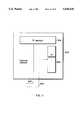
- FIG. 1is a perspective side view of the tennis training system according to the present invention
- FIG. 2is a top cross sectional view of head positions of the user of the system of FIG. 1;
- FIG. 3is a top level block diagram of the system of FIG. 1;
- FIG. 4is a circuit diagram of the system of FIG. 1;
- FIG. 5is a cross sectional view of a position sensor used with the system of FIG. 1;
- FIG. 6a, 6b, and 6cshow the sensor of FIG. 5 at various angles of tilt
- FIG. 7is a block diagram of a polling procedure
- FIG. 8illustrates the registers maintained by the polling procedure of FIG. 7
- FIG. 9is a block diagram of an interrupt procedure
- FIG. 10shows an alternative embodiment of the system of FIG. 1
- FIG. 11shows a position sensor having two tilt sensors mounted at right angles to each other.
- FIGS. 12a and 12bshow tilt sensors in the form of an accelerometer and leveling tube, respectively.
- FIG. 1is a side view of a tennis training system embodying the present invention as it would be worn on the head of a tennis player.
- the systemis used to teach the tennis player to maintain a proper "head-up" position while playing tennis.
- the systemincludes a position processor 2, mounted on a head band 3. It should be apparent to one skilled in the art, that other means can also be used to mount the position processor 2 on a tennis player's head. For example, the position processor 2 can be fixed to a cap worn by the tennis player.
- the player's headis maintained in an head-up position. That is, the axis of the head is maintained substantially vertical. When the head is so positioned, the player can easily track the rapidly moving ball, and balance is also improved. If the head is not positioned in a proper head-up position the player's performance is generally deteriorated.
- FIG. 2is a schematic cross section, of the head 5, as seen from above the tennis player.
- improper positions of the headare classified into four quadrants, each approximately ninety degrees in extent, for example, the quadrants, 5a, 5b, 5c, and 5d, generally labeled "FORWARD”, “BACKWARD,” “LEFT,” and “RIGHT.”
- FORWARDis the position when the head 5 of the tennis player is tilted generally forward, e.g., face down, or towards the ground.
- the other positionslikewise refer to the head 5 being tilted either to the back (BACKWARD), e.g., face upwards to the sky, LEFT (left ear lower than left ear, or RIGHT (right ear lower than left ear).
- BACKWARDback
- LEFTleft ear lower than left ear
- RIGHTright ear lower than left ear
- the positions of the headare conveyed to the tennis player by a visual unit and an audio unit, generally indicated by dashed lines 10 and 20, respectively.
- the visual and audio units, 10 and 20are used, as will be described in greater detail herein, to convey positional information of the head to the tennis player, or to a person who is teaching the tennis player, such as a professional tennis coach.
- the positional informationis sensed by a attitude and angle sensor 100 (FIG. 5) and processed by an electronic circuit (FIG. 4), including a microprocessor 40 running software (FIG. 7 and 9).
- the visual unit 10includes five light emitting diodes (LEDs), 11-15. LEDs 11-14 emit red light, and LED 15 emits green light. Depending on the position of the tennis player's head, the light patterns displayed are as follows: if the head is FORWARD, LEDs 11 and 12 are turned on; if the head is tilted BACKWARD, LEDs 13 and 14 are turned on; if the head is tilted LEFT, LEDs 11 and 13 are turned on; and if the head is tilted RIGHT, LEDs 12 and 14 are turned on. Otherwise, if the head is in the proper head-up position, or not tilted in any direction, the green LED 15 is on. It should be apparent to one skilled in the art that other light patterns and colors may also be used.
- the audio unit 20In conjunction with the positional information conveyed by the visual unit 10, the audio unit 20 generates audible tones: a 3000 Hz tone when the head is tilted FORWARD; a 1500 Hz tone when the head is tilted BACKWARD; a pulsed 3000 Hz tone if the head is tilted LEFT; and a pulsed 1500 Hz tone when the head is tilted RIGHT. No tone is generated when the head is substantially vertical.
- the audio unit 20by means of a digital voice synthesizer emits the words "FORWARD", “BACKWARDS”, “LEFT”, and "RIGHT” to indicate the positions of the head.
- the position processor 2includes a microprocessor 40, a position sensor 100, a multiplexer (MUX) 41, an angle/sensitivity selector (ASSEL) 42, a quadrant selector (QSEL) 44, a clocking circuit 45, and a power on/off circuit 46. Also shown in FIG. 4 are the visual unit 10 and the audio unit 20.
- the microprocessor 40is a Motorola MC68HC705J2.
- the microprocessor 40includes 2K bytes of memory for storing data and instructions, 64 general purpose registers, and input ports 40a and output ports 40b, for receiving and sending data, respectively.
- the position sensor 100will be described in further detail with respect to FIGS. 5 and 11.
- the position sensor 100is a conventional twelve position mercury switch. That is, the position sensor 100 includes 12 sensing ON/OFF switches 101-112.
- the sensor 100is mounted in the position processor 2, so that when the processor 2 is positioned on the head of the tennis player, the sensor is essentially level, and none of the ON/OFF switches of the mercury switch are in an ON position.
- each of the switches 101-112is connected to the MUX 41 via sense lines 41c, the other side is connected to the microprocessor 40 via sensor enable line 40v.
- the switches 101-112 of the sensor 100are selected by the microprocessor 40 via the MUX 41.
- the MUX 41is implemented with two National CD4052 multiplexer circuits 41a and 4lb.
- Each of the circuits 41a and 41bincludes eight sense lines 41c which are controlled from some of the output ports 40b of the microprocessor 40 by the select lines 41d to present switch information (ON/OFF states) to the input ports 40a of the microprocessor 40 on data lines 41e, each of the data lines 40e also connected to ground via a 10K ohm resistor 40p.
- sense lines 41cTwelve of the sixteen (2 ⁇ 8) sense lines 41c are used for the switches 101-112 of the sensor 100, the remaining four sense lines 41c are used for the ASSEL 42.
- the QSEL 44is connected directly to the input ports 40a of the microprocessor 40 via data lines: 41e.
- the ASSEL 42 and QSEL 44are implemented by using two conventional sixteen position (hex) rotary switches 42s and 44s, respectively. Suitable switches 42s and 44s are, for example, MORS ASC 65503 switches.
- the ASSEL 42is implemented by using the switch 42s, and the QSEL 44 is implemented by using switch 44s.
- the sixteen switch positions (0-15)are indicated by various combinations of four ON/OFF switches, that is 2 4 or 16 different combinations of the switch 42s and 44s are possible. For example, position "0" is indicated as OFF, OFF, OFF, OFF, position "1" as OFF, OFF, OFF, ON, and so forth.
- the QSEL 44also includes four diodes 44d configured in the circuit to allow independent isolation of switches 44s when read by the microprocessor 40.
- the clocking circuit 45includes a 4 MHz ceramic resonator 45a.
- the clocking circuit 45also includes a 4.7 Mohm resistor 45b and two 25 of capacitors 45c configured conventionally.
- the output of the clocking circuit 45that is, a 4 MHz clock signal, is connected to the microprocessor 40 via lines 46d.
- the power on-off circuit 46includes a 4.5 V battery 46a and a push-button power ON/OFF switch 46b.
- the resistor 46c and the capacitor 46d of the power on/off circuit 46are, respectively, 10K ohm and 0.1 micro farads.
- the power on/off circuit 46is connected to the microprocessor 40 via line 46e.
- the visual unit 10includes the LEDs 11-15, one side of each LED 11-15 connected to the output ports 40b of the microprocessor 40, and the other side of each of the LEDs 11-15 connected to ground via a 150 ohm resistors 10b.
- the audio unit 20is in the form of a piezo electric transducer 20a. One side of the transducer 20a is connected to one of the output ports 40b of the microprocessor 40, and the other side of the transducer 20a is connected to ground.
- the audio unit 20is in the form of a digital voice synthesizer, which generates the words "forward,” “backward,” “left,” and “right” to indicate the position of the head.
- the electrical operation of the position processor 2is first described. This description will be followed by a description of the software, in the form of instructions and data, permanently stored in the memory of the microprocessor 40, which is used to control and process the electrical signals of the position processor 2.
- the position processor 2is activated by the user, for example the tennis player pushing the power ON/OFF switch 46b of the power on/off circuit 46 to an "ON" position. This action causes the micro-processor 40 to exit a "sleep” mode and enter an "active” mode to power the various circuits 41-46, 10, and 20 of the position processor 2.
- the clock circuit 45generates the necessary clock signal to operate the microprocessor 40 via lines 46d.
- the supply of power to the microprocessorcauses a hardware interrupt which activates the execution of software.
- the software of the microprocessor 40is used to periodically sample the ON/OFF states of the position sensor switches 101-112, and the ON/OFF states of the switches 42s and 44s of the ASSEL 42 and the QSEL 44 by appropriately controlling the select lines 41d of the MUX 41.
- the ON/OFF states of the position sensor 100 switches 101-112, and the ASSEL 42 and the QSEL 44 switches 42s-44sare presented on data lines 41e to the input ports 40a of the microprocessor 40.
- the switch positions (ON or OFF)are processed by the software, and appropriate signals are supplied via the output ports 40b to the visual unit 10 and the audio unit 20 to give positional information to the user.
- the purpose and operation of the ASEL 42 and the QSEL 44will be described with reference to FIGS. 7 and 8.
- the position sensor 100is further described.
- the position sensor 100can be in the form of a miniature twelve position mercury switch. Such switches are well known in the art, and the basic construction and operation of the sensor 100 are only summarized here to facilitate an understanding of the present invention.
- Sensors of this typegenerally include an electrically conductive case 120, in the form of an inverted metallic can, positioned on a substantially planar dielectric mounting base, generally indicated by reference numeral 121.
- a droplet of mercuryis free to move inside the case 120.
- Twelve electrically conductive pins 101-112are circularly positioned, equal distant apart on the mounting base 121. The pins 101-112 protrude through the base 120 so that they may externally connect to the sense lines 41c of the MUX 41 of FIG. 4. Each of the pins 101-112 provide one side of an ON/OFF switch, and the case 120 provides the other side via line 40v.
- the mercury droplet 122is the means used to selectively connect the various pins 101-112 to the case 120 to indicate ON states. When the mercury droplet 122 is simultaneous touching the case 120 and any of the pins 101-112, electrical current can flow from the case 120 to the pins 101-112 to indicate an ON state, otherwise an OFF state is indicated.
- the mercury droplet 122When the mounting base 121 is essentially horizontal or level, the mercury droplet 122 is generally in the middle of the mounting base 121, as shown in FIG. 5, and all of the pins 101-112 of the sensor 100 are in an OFF state. However, if the sensor is tilted in any direction, the force of gravity causes the mercury droplet 122 to seek a lower position on the mounting base 121 and consequently one or more of the pins 101-112 will be shorted to the case 120 by the mercury droplet 122 to indicate an ON state.
- FIG. 6cshows the sensor 100 tilted to an even greater angle, for example the tilt being an angle greater than about 25 degrees, all of the mercury droplet 122 will be pooled along the periphery of the case 120, and as many as three of the pins 101-112, for example pins 107-109, will be in an ON state.
- variations in the manufacture of the sensor 100 or the volume of the mercury droplet 122may give different results.
- the sensor 100can be used to indicate the direction of tilt, as well as, the relative severity or angle of tilt of the sensor 100.
- the circular position of the pins 101-112 which are in an ON stategive the general direction of tilt
- the number of the pins 101-112 that are ONgive the relative angle of tilt of the sensor 100. Note that at any one time either 0, 1, 2, or 3 pins in an ON state, and that such pins are always adjacent.
- the pins 101-112 of the sensor 100are arbitrarily grouped into four groups 100a-100d of three pins each, corresponding to the quadrants 5a-5d, respectively, as shown in FIG. 2. That is, the pins 101-103 in quadrant 100a correspond to the FORWARD head position (5a), pins 107-109 (100b) to the BACKWARD head position (5b), the pins 110-112 (100c) to LEFT head position (5c), and the pins 104-106 (100d) to RIGHT head position (5d).
- the ON states of the pins 101-112can be used to determine the direction of tilt of the head of the tennis player.
- the number of the pins 101-112 that are on in one the quadrants 100a-100d of the sensor 100indicate the relative angle of tilt.
- a software programis provide to sample, process, filter, the sampled ON/OFF states of the switches 101-112 of the sensor, and to display the thus processed ON/OFF states as positional information to the user. Furthermore, the software permits the user to selectively control the sensitive of the position processor 2, and to select the manner in which positional information is presented by setting the switches of the angel/sensitivity selector (ASEL) 42 and the quadrant selector (QSEL) 44 appropriately.
- ASELangel/sensitivity selector
- QSELquadrant selector
- the softwareincludes a polling procedure for sampling and processing ON/OFF states collected from the switches 42s44s, and 101-112, and an interrupt procedure to convey the processed ON/OFF states of the switches to the user.
- FIG. 7shows the steps of the polling procedure 50.
- the polling procedurewill be described also with reference to FIG. 8 which shows the registers maintained by the polling procedure 50.
- the registers of FIG. 7include a sampling register (SAM-REG) 150 having twelve bits 151-162, each bit corresponding to one of the switches 101-112 of the sensor 100, respectively. A logical "0" in a bit indicating on OFF state, and a logical "1" indicating an 0N state of any one of the switches 101-112.
- SAM-REGsampling register
- Each of the CNTREGs 201-212can store a value in the range of 0 to 255.
- a processed count register (PRCREG) 300having twelve bits 301-312, one for each of the CNTREGs 201-212 respectively.
- a quadrant register (QUADREG) 400including four bits. 401-404, corresponding to groups of three bits of the PRCREG 300. That is, bits 301-303 representing a FORWARD (5a) position, bits 304-306 representing a RIGHT (5d) position, bits 307-309 representing a BACKWARD (5b) position, and bits 310-312 representing a LEFT (5c) position.
- the bits 401-404 of the QUADREGalso represent the four possible positions of the head.
- registers 420 and 440are for storing the sampled ON/OFF states of the ASSEL 42 and the QSEL 44, respectively.
- each of the bits 441-444represents the head position quadrants FORWARD (5a), RIGHT (5d), BACKWARD (5b), and LEFT (5c) of FIG. 2.
- Quadrant information as indicated in the bits 401-404 of the QUADREG 400will only be displayed if the corresponding bit in QREG 440 is also set to a logical "1," otherwise the quadrant information in QUADREG 400 will not be displayed.
- the bits 441-444 of the QREG 440are used as a logical AND function.
- bits 441 and 443 of the QREG 420are set to a logical "1", e.g., the binary value of QREG 420 is "1010" (i.e., decimal 10), that is rotary switch 42s is set to position "10", positional information will only be conveyed to the user if the head is tilted either FORWARD or BACKWARD.
- the bits 421-424 of the ASREG 420are used to select predetermined combinations of angle settings and sensitivity with the ASSEL 44 as summarized in Table 1 below.
- the angle of tilt of the sensor 100determined by an arbitrary angle setting, in the range of 1 to 3, the angle settings corresponding to the number of the pins 101-112 that are in an ON state.
- the sensitivitydetermined by the rate at which the sensor 100 is sampled. Sampling the various switches 100, 42s and 44s at a higher rate making the system more sensitive, or more quickly responsive to changes in positions of the head. Sampling the switches at a lower rate makes the system less sensitive to changes in position.
- the rateis determined by multiplying a predetermined time delay, for example 0.4 ms by a predetermined sampling rate selected from values 5, 25, 50, 75, 100, 150,170, or 250.
- the delay periodbeing a period of time between successive sampling of the sensor 100.
- a sampling rate of 5corresponding to the sensor 100 being sampled approximately every 2 ms, and a sampling rate of 25 causing the sensor to be sampled every 50 ms, and so forth.
- sampling rate and anglewere empirically determined by use of the tracing system with a variety of players of different skill level and relative body motion. It should be obvious to one skilled in the art, that many other combinations are also possible.
- All of the registers 150, 201-212, 300, 400, 420, and 440are initialized to logical "0" when the position processor 2 is turned on.
- switches 42s and 44sare sampled as to their ON/OFF states.
- the resulting ON/OFF statesare stored in ASREG 420 and QREG 440, respectively, as bit patterns consisting of logical "0"s and logical "1"s.
- step 52the polling procedure 50 determines the appropriate polling rate as indicated by the contents of ASREG 420 and delays execution of the procedure 50 for that period of time to achieve the desired polling rate or sensitivity of the training system. At the expiration of the predetermined time delay period, step 53 is executed.
- Step 53is used to sample the ON/OFF states of the switches 101-112 of the sensor 100.
- the switches 101-112are sampled by the instructions of the step 52 selecting the switches 101-112 in turn via the MUX 41.
- the ON/OFF state of each of the switches 101-112are stored in the bits 151-162 of the SAMREG 150, a logical "0" or "1” indicating, respectively, either on OFF or ON state of the corresponding switch 101-112 of the sensor 100 during a polling cycle.
- a polling cyclebeing one loop through the steps of the polling procedure 50.
- Step 54is used to maintain the raw counts of CNTREGs 201-212.
- the CNTREGs 201-212are essentially used to indicate how long (or short) each of the switches 101-112 have been either ON or OFF. That is, in step 54, each of values stored in the CNTREGs 201-212 is incremented if the corresponding bit 151-162 of SAMREG 150 is a logical "1," otherwise the value is decremented. Note that the values stored in CNTREG 201-212 are not incremented over 255, nor decremented below 0. In other words, a high count in one of the registers 201-212 is indicative that a particular one of the switches 101-112 is more ON than OFF, a low count indicating the opposite. Or stated otherwise, a high count indicates that the head of the tennis player tends to be tilted in the direction of the pins 101-112 with the highest count.
- step 55the counts stored in the CNTREG 201-212 are processed to give a general indication if one of the switches 101-112 is more ON than OFF.
- the countsare processed as follows. If one of the CNTREGs 201-212 stores a count greater than a HIGH threshold, the corresponding switch 101-112 is deemed to be mostly ON, and therefore, the corresponding bit 301-312 in the PRCREG 300 is set to a logical "1". If the count in one the CNTREGSs 201-212 is less than a LOW threshold the corresponding one of the bits 301-312 of the PRCREG is set to logical "0" to indicate that the corresponding switch 101-112 was mostly OFF.
- the LOW and HIGH thresholdsare spaced apart to provide sufficient hysterisis to filter out sporadic changes of ON and OFF states of the switches 101-112 induced by the spurious movement of the mercury droplet 122 inside the sensor 100 as the user moves about.
- the HIGH and LOW thresholdsin the preferred embodiment, as empirically determined to give good results, are set to counts of 192 and 64, respectively.
- step 56the processed raw counts are further evaluated as follows. If one, two, or three adjacent bits in any one group of three bits 301-303, 304-306, 307-309, and 310-312 of the PRCREG 300 are set to a logical "1" proceed to step 57. If two adjacent bits in any two adjacent groups of bits are set, shift the bits 301-312 right one position, with end around carry, and proceed with step 57. If two adjacent bits are set in one group and one bit is set in an adjacent group, clear the single bit and set the third bit in the group already having two bits sets, proceed with step 57.
- step 57the quadrant register QUADREG 400 is set to the quadrant positions, FORWARD (5a), BACKWARD (5b), LEFT 5c, and RIGHT (5d) by setting the corresponding bits 401, 403, 402 and 404 of QUADREG 400 as follows.
- One of the bits 401-404 in QUADREG 400is set to a logical "1" if any of the bits of the corresponding groups of bits are set in PRCREG to a logical "1" as evaluated in step 56. Otherwise, set the corresponding bit to logical "O".
- Step 58determines angle of tilt of the sensor 100. If the angle setting is 3, all of the bits in a quadrant group of three in the PRCREG 300 must be set to logical "1" to indicate that the sensor 100 is tilted to a greatest angle. Otherwise set the corresponding bit in QUADREG 400 to logical "0". If the angle setting is 2, at least two bits in a quadrant group must be logical "1" in PRCREG 300, otherwise clear the corresponding bit in QUADREG 400. And, if the angle setting is 1, any one bit of a group of quadrant bits being logical "1" is sufficient to indicate that the sensor 100 is tilted at least a minimal angle.
- step 58 of polling procedure 50execution proceeds in a repetitive and circular fashion with step 51.
- the function of the polling procedureis therefore, to sample the ON/OFF states of the switches at a predetermined sampling rate, the sampling rate determining the sensitivity of the training system.
- the procedure 50evaluates and processes the sampled ON/OFF states to reduce states to positional information, including the direction and angle of tilt of the head of the user.
- FIG. 9shows the steps of the interrupt procedure 60 of the software of the position processor 2.
- the LEDS 11-15are turned ON or OFF depending on the bits 401-404 of the QUADREG 400 as processed by the steps 51-58 of the polling procedure 50. That is LEDS 11 and 12 are turned ON if bit 401 is logical "1", LEDS 13 and 14 are turned ON if bit 403 is logical "1", LEDS 11 and 13 are turned on if bit 404 is logical "1”, and LEDS 12 and 14 are turned ON if bit 402 is logical "1", otherwise if the bits 401-404 are all logical "0", turn on LED 15.
- step 62the corresponding audible signals are generated.
- the pulsed and unpulsed tones at 3000, 1500 Hzare generated by using the internal timers of the microprocessor 40 which are initialized to generate interrupts at appropriate frequencies.
- step 63a 60 second interrupt time-out is maintained, to determine if any changes of positions have occurred in the last 60 seconds. If no changes in positions have been detected, the instructions of step 63 place the microprocessor 40 in a low power sleep state in order to conserve power.
- FIG. 10shows an alternative embodiment of the invention.
- a position sensor 500includes two tilt sensors mounted at right angles to each other.
- the tilt sensorsdescribed below with reference to FIG. 11, produce output voltages on lines 502 and 503.
- the output voltagesare continuously proportional to the amount of tilt in the "x" and "y” direction of the two tilt sensors, respectively.
- the x and y directioncorresponding to the axes along which the two sensors are mounted.
- the output voltages of the two sensorscan be converted to a pair of digital signals by an analog to digital convertor 501 of the microprocessor 40.
- the digital signalscan be pairs of data values in the range of 0 to 255 representing the output voltages of the two tilt sensors.
- the pairs of data valuescan be combined by, for example, an inverse tangent function to calculate directional values of the sensors with respect to the x axis and the y axis. For example, if the voltages are equal in sign and magnitude the direction of tilt is half-way between the right angle at which the sensors are mounted. A higher voltage indicates a greater magnitude of the tilt than a lower voltage.
- the directional valuescan be partitioned into ranges representing, for example, 30 degrees. Each 30 degree range corresponding to one of the bits 150-162 of the raw count sample register SAMREG 150 of FIG. 8.
- the filtering and hysterisis method 50 of FIG. 7can be performed as described above.
- FIG. 11shows the position sensor 500 in greater detail.
- the sensor 500includes an "X” sensor 504 and a “Y” sensor 505.
- the sensors 504 and 505are mounted at right angles to each other.
- the output voltage of the "X” sensor 504corresponding to the relative angle of tilt along the x-axis, and the "Y” sensor 505 gives the angle of tilt along the y-axis.
- the voltagesare presented on lines 502 and 503 for processing by the microprocessor 40 of FIG. 10.
- the tilt sensors 504 and 505can be in the form of a conventional accelerometer 600, as shown in FIG. 12a or, as shown in FIG. 126, a fluid-filled curved glass leveling 610 having an infra-red light source 620 and two infra-red detectors 630 to measure the relative position of an air bubble 640 in the fluid 650.
- the training systemcan be provided with a self-centering feature to make the system easier to use by the athlete.
- calibrating voltage samplesare taken from the tilt sensors 504 and 505 to determine base or reference values. In other words, during calibration, the sampled voltages represent the proper position of the head, regardless of the relative position of the system with respect to the athlete.
- the reference valuescan be extracted from samples taken during a predetermined time period, for example 1/2 a second after the system is initially activated by the ON/OFF switch 46b of FIG. 4.
- the reference samplescan be, for example tabularized, and stored in a set 130 of reference registers (REFREG) 131-142, for example, as shown in FIG. 8.
- REFREGreference registers
- any subsequent samples during actual use of the systemcan then adjusted or normalized by the base or reference values of REFREG 131-142, so that the position of the athlete's head can be given as the relative tilt of the head from the proper position.
- the userdoes not have to do any tedious repositioning of the device during use. Instead the user merely mounts the training system on the head, assumes a proper head-up position, and activates the device to calibrate it, and starts using the training system.
Landscapes
- Health & Medical Sciences (AREA)
- Life Sciences & Earth Sciences (AREA)
- General Health & Medical Sciences (AREA)
- Physics & Mathematics (AREA)
- Biomedical Technology (AREA)
- Molecular Biology (AREA)
- Dentistry (AREA)
- Biophysics (AREA)
- Pathology (AREA)
- Engineering & Computer Science (AREA)
- Physiology (AREA)
- Heart & Thoracic Surgery (AREA)
- Medical Informatics (AREA)
- Oral & Maxillofacial Surgery (AREA)
- Surgery (AREA)
- Animal Behavior & Ethology (AREA)
- Geometry (AREA)
- Public Health (AREA)
- Veterinary Medicine (AREA)
- Physical Education & Sports Medicine (AREA)
- Length Measuring Devices With Unspecified Measuring Means (AREA)
Abstract
Description
TABLE 1 ______________________________________ Switch Logical Sampling Position States Angle Setting ______________________________________ 0 0000 1 5 1 0001 2 5 2 0010 3 5 3 0011 1 25 4 0100 2 25 5 0101 1 75 6 0110 2 75 7 0111 3 50 8 1000 1 100 9 1001 2 100 10 1010 1 150 11 1011 3 75 12 1100 2 150 13 1101 3 100 14 1110 3 170 15 1111 3 250 ______________________________________
Claims (17)
Priority Applications (1)
| Application Number | Priority Date | Filing Date | Title |
|---|---|---|---|
| US08/172,118US5430435A (en) | 1992-11-13 | 1993-12-22 | Adjustable athletic training system |
Applications Claiming Priority (2)
| Application Number | Priority Date | Filing Date | Title |
|---|---|---|---|
| US07/976,175US5300921A (en) | 1992-11-13 | 1992-11-13 | Athletic training system |
| US08/172,118US5430435A (en) | 1992-11-13 | 1993-12-22 | Adjustable athletic training system |
Related Parent Applications (1)
| Application Number | Title | Priority Date | Filing Date |
|---|---|---|---|
| US07976175Continuation-In-Part | 1993-11-13 |
Publications (1)
| Publication Number | Publication Date |
|---|---|
| US5430435Atrue US5430435A (en) | 1995-07-04 |
Family
ID=46248299
Family Applications (1)
| Application Number | Title | Priority Date | Filing Date |
|---|---|---|---|
| US08/172,118Expired - LifetimeUS5430435A (en) | 1992-11-13 | 1993-12-22 | Adjustable athletic training system |
Country Status (1)
| Country | Link |
|---|---|
| US (1) | US5430435A (en) |
Cited By (72)
| Publication number | Priority date | Publication date | Assignee | Title |
|---|---|---|---|---|
| US5694340A (en)* | 1995-04-05 | 1997-12-02 | Kim; Charles Hongchul | Method of training physical skills using a digital motion analyzer and an accelerometer |
| US5745028A (en)* | 1994-04-29 | 1998-04-28 | Sound Motion, Inc. | Directional motion instrumentation system |
| WO1999034879A1 (en)* | 1998-01-07 | 1999-07-15 | Pragmatic Designs, Inc. | Electronic counting apparatus for a child's game and method therefor |
| US5941836A (en)* | 1996-06-12 | 1999-08-24 | Friedman; Mark B. | Patient position monitor |
| EP1030595A4 (en)* | 1997-10-24 | 2001-03-28 | Creative Sports Technologies I | Head gear for detecting head motion and providing an indication of head movement |
| US6263836B1 (en) | 1998-11-27 | 2001-07-24 | Robert L. Hollis | Dog behavior monitoring and training apparatus |
| US6307481B1 (en)* | 1999-09-15 | 2001-10-23 | Ilife Systems, Inc. | Systems for evaluating movement of a body and methods of operating the same |
| US6331168B1 (en) | 1997-10-24 | 2001-12-18 | Creative Sports Technologies, Inc. | Golf training head gear for detecting head motion and providing an indication of head movement |
| US6487992B1 (en)* | 1999-11-22 | 2002-12-03 | Robert L. Hollis | Dog behavior monitoring and training apparatus |
| US20030146844A1 (en)* | 1999-09-15 | 2003-08-07 | Ilife Solutions, Inc. | Systems within a communication device for evaluating movement of a body and methods of operating the same |
| US6700499B2 (en)* | 2000-10-16 | 2004-03-02 | Omron Corporation | Body motion detector |
| US6703939B2 (en)* | 1999-09-15 | 2004-03-09 | Ilife Solutions, Inc. | System and method for detecting motion of a body |
| US6730047B2 (en) | 1997-10-24 | 2004-05-04 | Creative Sports Technologies, Inc. | Head gear including a data augmentation unit for detecting head motion and providing feedback relating to the head motion |
| US20040116837A1 (en)* | 2002-10-02 | 2004-06-17 | Seiko Epson Corporation | Body motion detector |
| US20050145200A1 (en)* | 2004-01-07 | 2005-07-07 | Napolez Francisco J. | Neck motion detector and method for bark control device |
| FR2868281A1 (en)* | 2004-03-30 | 2005-10-07 | Commissariat Energie Atomique | METHOD FOR DETERMINING THE MOVEMENTS OF A PERSON |
| US20070015611A1 (en)* | 2005-07-13 | 2007-01-18 | Ultimate Balance, Inc. | Orientation and motion sensing in athletic training systems, physical rehabilitation and evaluation systems, and hand-held devices |
| WO2005021102A3 (en)* | 2003-08-21 | 2007-06-14 | Ultimate Balance Inc | Adjustable training system for athletics and physical rehabilitation including student unit and remote unit communicable therewith |
| US20070169364A1 (en)* | 2001-02-23 | 2007-07-26 | Microstrain, Inc. | Posture and body movement measuring system |
| US20070211050A1 (en)* | 2006-03-09 | 2007-09-13 | Nintendo Co., Ltd. | Coordinate calculating apparatus and coordinate calculating program |
| US20080065319A1 (en)* | 2004-01-16 | 2008-03-13 | Graham Andrew J | Wireless device, program products and methods of using a wireless device to deliver services |
| US20080288200A1 (en)* | 2007-05-18 | 2008-11-20 | Noble Christopher R | Newtonian physical activity monitor |
| US20080291163A1 (en)* | 2004-04-30 | 2008-11-27 | Hillcrest Laboratories, Inc. | 3D Pointing Devices with Orientation Compensation and Improved Usability |
| US20090045966A1 (en)* | 2007-07-20 | 2009-02-19 | Marko Rocznik | Clothing means having a sensor element for detecting a left position |
| US7716008B2 (en) | 2007-01-19 | 2010-05-11 | Nintendo Co., Ltd. | Acceleration data processing program, and storage medium, and acceleration data processing apparatus for use with the same |
| US20100156653A1 (en)* | 2007-05-14 | 2010-06-24 | Ajit Chaudhari | Assessment device |
| US7774155B2 (en) | 2006-03-10 | 2010-08-10 | Nintendo Co., Ltd. | Accelerometer-based controller |
| US7877224B2 (en) | 2006-03-28 | 2011-01-25 | Nintendo Co, Ltd. | Inclination calculation apparatus and inclination calculation program, and game apparatus and game program |
| US7927216B2 (en) | 2005-09-15 | 2011-04-19 | Nintendo Co., Ltd. | Video game system with wireless modular handheld controller |
| US7927253B2 (en) | 2007-08-17 | 2011-04-19 | Adidas International Marketing B.V. | Sports electronic training system with electronic gaming features, and applications thereof |
| US7931535B2 (en) | 2005-08-22 | 2011-04-26 | Nintendo Co., Ltd. | Game operating device |
| US7942745B2 (en) | 2005-08-22 | 2011-05-17 | Nintendo Co., Ltd. | Game operating device |
| CN102188249A (en)* | 2010-03-08 | 2011-09-21 | 精工爱普生株式会社 | Fall detecting device and fall detecting method |
| US8089458B2 (en) | 2000-02-22 | 2012-01-03 | Creative Kingdoms, Llc | Toy devices and methods for providing an interactive play experience |
| US8157651B2 (en) | 2005-09-12 | 2012-04-17 | Nintendo Co., Ltd. | Information processing program |
| US8226493B2 (en) | 2002-08-01 | 2012-07-24 | Creative Kingdoms, Llc | Interactive play devices for water play attractions |
| US8267786B2 (en) | 2005-08-24 | 2012-09-18 | Nintendo Co., Ltd. | Game controller and game system |
| US8308563B2 (en) | 2005-08-30 | 2012-11-13 | Nintendo Co., Ltd. | Game system and storage medium having game program stored thereon |
| US8313379B2 (en) | 2005-08-22 | 2012-11-20 | Nintendo Co., Ltd. | Video game system with wireless modular handheld controller |
| US8360904B2 (en) | 2007-08-17 | 2013-01-29 | Adidas International Marketing Bv | Sports electronic training system with sport ball, and applications thereof |
| US8409003B2 (en) | 2005-08-24 | 2013-04-02 | Nintendo Co., Ltd. | Game controller and game system |
| US20130130845A1 (en)* | 2001-09-12 | 2013-05-23 | Pillar Vision, Inc. | Trajectory detection and feedback system for tennis |
| US20130153206A1 (en)* | 2011-12-14 | 2013-06-20 | Baker Hughes Incorporated | Apparatus and methods for determining parameters downhole using gravity-affected sensor |
| US8475275B2 (en) | 2000-02-22 | 2013-07-02 | Creative Kingdoms, Llc | Interactive toys and games connecting physical and virtual play environments |
| US8493822B2 (en) | 2010-07-14 | 2013-07-23 | Adidas Ag | Methods, systems, and program products for controlling the playback of music |
| US8608535B2 (en) | 2002-04-05 | 2013-12-17 | Mq Gaming, Llc | Systems and methods for providing an interactive game |
| US8629836B2 (en) | 2004-04-30 | 2014-01-14 | Hillcrest Laboratories, Inc. | 3D pointing devices with orientation compensation and improved usability |
| US8702430B2 (en) | 2007-08-17 | 2014-04-22 | Adidas International Marketing B.V. | Sports electronic training system, and applications thereof |
| US8702515B2 (en) | 2002-04-05 | 2014-04-22 | Mq Gaming, Llc | Multi-platform gaming system using RFID-tagged toys |
| US8708821B2 (en) | 2000-02-22 | 2014-04-29 | Creative Kingdoms, Llc | Systems and methods for providing interactive game play |
| US8753165B2 (en) | 2000-10-20 | 2014-06-17 | Mq Gaming, Llc | Wireless toy systems and methods for interactive entertainment |
| US8758136B2 (en) | 1999-02-26 | 2014-06-24 | Mq Gaming, Llc | Multi-platform gaming systems and methods |
| JP2015150134A (en)* | 2014-02-13 | 2015-08-24 | 株式会社ユピテル | Sway detector, sway detection system, and sway detection program |
| US9261978B2 (en) | 2004-04-30 | 2016-02-16 | Hillcrest Laboratories, Inc. | 3D pointing devices and methods |
| US9446319B2 (en) | 2003-03-25 | 2016-09-20 | Mq Gaming, Llc | Interactive gaming toy |
| US9656120B1 (en)* | 2016-01-22 | 2017-05-23 | Jorge Romero Franco | Fitness level |
| WO2017223184A1 (en)* | 2016-06-22 | 2017-12-28 | Leaf Healthcare, Inc. | Systems and methods for displaying sensor-based user orientation information |
| US10004447B2 (en) | 2010-04-22 | 2018-06-26 | Leaf Healthcare, Inc. | Systems and methods for collecting and displaying user orientation information on a user-worn sensor device |
| US10140837B2 (en) | 2010-04-22 | 2018-11-27 | Leaf Healthcare, Inc. | Systems, devices and methods for the prevention and treatment of pressure ulcers, bed exits, falls, and other conditions |
| US10159897B2 (en) | 2004-11-23 | 2018-12-25 | Idhl Holdings, Inc. | Semantic gaming and application transformation |
| US10258258B2 (en) | 2010-03-07 | 2019-04-16 | Leaf Healthcare, Inc. | Systems, devices and methods for the prevention and treatment of pressure ulcers, bed exits, falls, and other conditions |
| US10588565B2 (en) | 2010-04-22 | 2020-03-17 | Leaf Healthcare, Inc. | Calibrated systems, devices and methods for preventing, detecting, and treating pressure-induced ischemia, pressure ulcers, and other conditions |
| US10631732B2 (en) | 2009-03-24 | 2020-04-28 | Leaf Healthcare, Inc. | Systems and methods for displaying sensor-based user orientation information |
| US10758162B2 (en) | 2010-04-22 | 2020-09-01 | Leaf Healthcare, Inc. | Systems, devices and methods for analyzing a person status based at least on a detected orientation of the person |
| US11051751B2 (en) | 2010-04-22 | 2021-07-06 | Leaf Healthcare, Inc. | Calibrated systems, devices and methods for preventing, detecting, and treating pressure-induced ischemia, pressure ulcers, and other conditions |
| US11135477B1 (en)* | 2019-07-23 | 2021-10-05 | Philippos Kneknas | Exercise apparatus calibration system |
| US20220000426A1 (en)* | 2018-11-06 | 2022-01-06 | Jason Friedman | Multi-modal brain-computer interface based system and method |
| US11272860B2 (en) | 2010-04-22 | 2022-03-15 | Leaf Healthcare, Inc. | Sensor device with a selectively activatable display |
| US11278237B2 (en) | 2010-04-22 | 2022-03-22 | Leaf Healthcare, Inc. | Devices, systems, and methods for preventing, detecting, and treating pressure-induced ischemia, pressure ulcers, and other conditions |
| US11369309B2 (en) | 2010-04-22 | 2022-06-28 | Leaf Healthcare, Inc. | Systems and methods for managing a position management protocol based on detected inclination angle of a person |
| US11980449B2 (en) | 2010-04-22 | 2024-05-14 | Leaf Healthcare, Inc. | Systems and methods for monitoring orientation and biometric data using acceleration data |
| US12105208B2 (en) | 2004-06-30 | 2024-10-01 | Adidas Ag | Systems and methods for providing a health coaching message |
Citations (6)
| Publication number | Priority date | Publication date | Assignee | Title |
|---|---|---|---|---|
| US2754497A (en)* | 1954-03-04 | 1956-07-10 | Wolpert Edward | Device for keeping vehicle operators alert |
| US3362023A (en)* | 1965-06-01 | 1968-01-02 | William G. Mcmahon | Golfer's aid |
| US4527982A (en)* | 1981-10-27 | 1985-07-09 | Norman Salzman | Body coordination training aid |
| US4665388A (en)* | 1984-11-05 | 1987-05-12 | Bernard Ivie | Signalling device for weight lifters |
| US5005835A (en)* | 1989-07-14 | 1991-04-09 | Value Engineering Co. | Golf swing head movement monitoring apparatus |
| US5158089A (en)* | 1991-07-05 | 1992-10-27 | Swezey Robert L | Posture-monitoring headband device |
- 1993
- 1993-12-22USUS08/172,118patent/US5430435A/ennot_activeExpired - Lifetime
Patent Citations (6)
| Publication number | Priority date | Publication date | Assignee | Title |
|---|---|---|---|---|
| US2754497A (en)* | 1954-03-04 | 1956-07-10 | Wolpert Edward | Device for keeping vehicle operators alert |
| US3362023A (en)* | 1965-06-01 | 1968-01-02 | William G. Mcmahon | Golfer's aid |
| US4527982A (en)* | 1981-10-27 | 1985-07-09 | Norman Salzman | Body coordination training aid |
| US4665388A (en)* | 1984-11-05 | 1987-05-12 | Bernard Ivie | Signalling device for weight lifters |
| US5005835A (en)* | 1989-07-14 | 1991-04-09 | Value Engineering Co. | Golf swing head movement monitoring apparatus |
| US5158089A (en)* | 1991-07-05 | 1992-10-27 | Swezey Robert L | Posture-monitoring headband device |
Cited By (202)
| Publication number | Priority date | Publication date | Assignee | Title |
|---|---|---|---|---|
| US5745028A (en)* | 1994-04-29 | 1998-04-28 | Sound Motion, Inc. | Directional motion instrumentation system |
| US5694340A (en)* | 1995-04-05 | 1997-12-02 | Kim; Charles Hongchul | Method of training physical skills using a digital motion analyzer and an accelerometer |
| US5941836A (en)* | 1996-06-12 | 1999-08-24 | Friedman; Mark B. | Patient position monitor |
| US6129686A (en)* | 1996-06-12 | 2000-10-10 | Friedman; Mark B. | Patient position monitor |
| US6730047B2 (en) | 1997-10-24 | 2004-05-04 | Creative Sports Technologies, Inc. | Head gear including a data augmentation unit for detecting head motion and providing feedback relating to the head motion |
| EP1030595A4 (en)* | 1997-10-24 | 2001-03-28 | Creative Sports Technologies I | Head gear for detecting head motion and providing an indication of head movement |
| US6331168B1 (en) | 1997-10-24 | 2001-12-18 | Creative Sports Technologies, Inc. | Golf training head gear for detecting head motion and providing an indication of head movement |
| US20040225236A1 (en)* | 1997-10-24 | 2004-11-11 | Creative Sports Technologies, Inc. | Head gear including a data augmentation unit for detecting head motion and providing feedback relating to the head motion |
| WO1999034879A1 (en)* | 1998-01-07 | 1999-07-15 | Pragmatic Designs, Inc. | Electronic counting apparatus for a child's game and method therefor |
| US5989120A (en)* | 1998-01-07 | 1999-11-23 | Pragmatic Designs, Inc. | Electronic counting apparatus for a child's game and method therefor |
| US6263836B1 (en) | 1998-11-27 | 2001-07-24 | Robert L. Hollis | Dog behavior monitoring and training apparatus |
| US8888576B2 (en) | 1999-02-26 | 2014-11-18 | Mq Gaming, Llc | Multi-media interactive play system |
| US8758136B2 (en) | 1999-02-26 | 2014-06-24 | Mq Gaming, Llc | Multi-platform gaming systems and methods |
| US9731194B2 (en) | 1999-02-26 | 2017-08-15 | Mq Gaming, Llc | Multi-platform gaming systems and methods |
| US9861887B1 (en) | 1999-02-26 | 2018-01-09 | Mq Gaming, Llc | Multi-platform gaming systems and methods |
| US9186585B2 (en) | 1999-02-26 | 2015-11-17 | Mq Gaming, Llc | Multi-platform gaming systems and methods |
| US9468854B2 (en) | 1999-02-26 | 2016-10-18 | Mq Gaming, Llc | Multi-platform gaming systems and methods |
| US10300374B2 (en) | 1999-02-26 | 2019-05-28 | Mq Gaming, Llc | Multi-platform gaming systems and methods |
| US6703939B2 (en)* | 1999-09-15 | 2004-03-09 | Ilife Solutions, Inc. | System and method for detecting motion of a body |
| US20030146844A1 (en)* | 1999-09-15 | 2003-08-07 | Ilife Solutions, Inc. | Systems within a communication device for evaluating movement of a body and methods of operating the same |
| US6864796B2 (en) | 1999-09-15 | 2005-03-08 | Ilife Solutions, Inc. | Systems within a communication device for evaluating movement of a body and methods of operating the same |
| US6307481B1 (en)* | 1999-09-15 | 2001-10-23 | Ilife Systems, Inc. | Systems for evaluating movement of a body and methods of operating the same |
| US6487992B1 (en)* | 1999-11-22 | 2002-12-03 | Robert L. Hollis | Dog behavior monitoring and training apparatus |
| US9713766B2 (en) | 2000-02-22 | 2017-07-25 | Mq Gaming, Llc | Dual-range wireless interactive entertainment device |
| US10307671B2 (en) | 2000-02-22 | 2019-06-04 | Mq Gaming, Llc | Interactive entertainment system |
| US8475275B2 (en) | 2000-02-22 | 2013-07-02 | Creative Kingdoms, Llc | Interactive toys and games connecting physical and virtual play environments |
| US9474962B2 (en) | 2000-02-22 | 2016-10-25 | Mq Gaming, Llc | Interactive entertainment system |
| US9579568B2 (en) | 2000-02-22 | 2017-02-28 | Mq Gaming, Llc | Dual-range wireless interactive entertainment device |
| US8686579B2 (en) | 2000-02-22 | 2014-04-01 | Creative Kingdoms, Llc | Dual-range wireless controller |
| US10188953B2 (en) | 2000-02-22 | 2019-01-29 | Mq Gaming, Llc | Dual-range wireless interactive entertainment device |
| US8184097B1 (en) | 2000-02-22 | 2012-05-22 | Creative Kingdoms, Llc | Interactive gaming system and method using motion-sensitive input device |
| US8790180B2 (en) | 2000-02-22 | 2014-07-29 | Creative Kingdoms, Llc | Interactive game and associated wireless toy |
| US8169406B2 (en) | 2000-02-22 | 2012-05-01 | Creative Kingdoms, Llc | Motion-sensitive wand controller for a game |
| US9814973B2 (en) | 2000-02-22 | 2017-11-14 | Mq Gaming, Llc | Interactive entertainment system |
| US8531050B2 (en) | 2000-02-22 | 2013-09-10 | Creative Kingdoms, Llc | Wirelessly powered gaming device |
| US8814688B2 (en) | 2000-02-22 | 2014-08-26 | Creative Kingdoms, Llc | Customizable toy for playing a wireless interactive game having both physical and virtual elements |
| US8164567B1 (en) | 2000-02-22 | 2012-04-24 | Creative Kingdoms, Llc | Motion-sensitive game controller with optional display screen |
| US8368648B2 (en) | 2000-02-22 | 2013-02-05 | Creative Kingdoms, Llc | Portable interactive toy with radio frequency tracking device |
| US8089458B2 (en) | 2000-02-22 | 2012-01-03 | Creative Kingdoms, Llc | Toy devices and methods for providing an interactive play experience |
| US9149717B2 (en) | 2000-02-22 | 2015-10-06 | Mq Gaming, Llc | Dual-range wireless interactive entertainment device |
| US8708821B2 (en) | 2000-02-22 | 2014-04-29 | Creative Kingdoms, Llc | Systems and methods for providing interactive game play |
| US8491389B2 (en) | 2000-02-22 | 2013-07-23 | Creative Kingdoms, Llc. | Motion-sensitive input device and interactive gaming system |
| US8915785B2 (en) | 2000-02-22 | 2014-12-23 | Creative Kingdoms, Llc | Interactive entertainment system |
| US6700499B2 (en)* | 2000-10-16 | 2004-03-02 | Omron Corporation | Body motion detector |
| US8753165B2 (en) | 2000-10-20 | 2014-06-17 | Mq Gaming, Llc | Wireless toy systems and methods for interactive entertainment |
| US9320976B2 (en) | 2000-10-20 | 2016-04-26 | Mq Gaming, Llc | Wireless toy systems and methods for interactive entertainment |
| US10307683B2 (en) | 2000-10-20 | 2019-06-04 | Mq Gaming, Llc | Toy incorporating RFID tag |
| US9480929B2 (en) | 2000-10-20 | 2016-11-01 | Mq Gaming, Llc | Toy incorporating RFID tag |
| US9931578B2 (en) | 2000-10-20 | 2018-04-03 | Mq Gaming, Llc | Toy incorporating RFID tag |
| US8961260B2 (en) | 2000-10-20 | 2015-02-24 | Mq Gaming, Llc | Toy incorporating RFID tracking device |
| US8248367B1 (en) | 2001-02-22 | 2012-08-21 | Creative Kingdoms, Llc | Wireless gaming system combining both physical and virtual play elements |
| US8384668B2 (en) | 2001-02-22 | 2013-02-26 | Creative Kingdoms, Llc | Portable gaming device and gaming system combining both physical and virtual play elements |
| US10758818B2 (en) | 2001-02-22 | 2020-09-01 | Mq Gaming, Llc | Wireless entertainment device, system, and method |
| US9737797B2 (en) | 2001-02-22 | 2017-08-22 | Mq Gaming, Llc | Wireless entertainment device, system, and method |
| US9162148B2 (en) | 2001-02-22 | 2015-10-20 | Mq Gaming, Llc | Wireless entertainment device, system, and method |
| US9393491B2 (en) | 2001-02-22 | 2016-07-19 | Mq Gaming, Llc | Wireless entertainment device, system, and method |
| US8711094B2 (en) | 2001-02-22 | 2014-04-29 | Creative Kingdoms, Llc | Portable gaming device and gaming system combining both physical and virtual play elements |
| US10179283B2 (en) | 2001-02-22 | 2019-01-15 | Mq Gaming, Llc | Wireless entertainment device, system, and method |
| US8913011B2 (en) | 2001-02-22 | 2014-12-16 | Creative Kingdoms, Llc | Wireless entertainment device, system, and method |
| US20070169364A1 (en)* | 2001-02-23 | 2007-07-26 | Microstrain, Inc. | Posture and body movement measuring system |
| US7698830B2 (en) | 2001-02-23 | 2010-04-20 | Microstrain, Inc. | Posture and body movement measuring system |
| US10092793B1 (en)* | 2001-09-12 | 2018-10-09 | Pillar Vision, Inc. | Trajectory detection and feedback systems for tennis |
| US20130130845A1 (en)* | 2001-09-12 | 2013-05-23 | Pillar Vision, Inc. | Trajectory detection and feedback system for tennis |
| US9694238B2 (en)* | 2001-09-12 | 2017-07-04 | Pillar Vision, Inc. | Trajectory detection and feedback system for tennis |
| US9616334B2 (en) | 2002-04-05 | 2017-04-11 | Mq Gaming, Llc | Multi-platform gaming system using RFID-tagged toys |
| US9463380B2 (en) | 2002-04-05 | 2016-10-11 | Mq Gaming, Llc | System and method for playing an interactive game |
| US10478719B2 (en) | 2002-04-05 | 2019-11-19 | Mq Gaming, Llc | Methods and systems for providing personalized interactive entertainment |
| US10507387B2 (en) | 2002-04-05 | 2019-12-17 | Mq Gaming, Llc | System and method for playing an interactive game |
| US8702515B2 (en) | 2002-04-05 | 2014-04-22 | Mq Gaming, Llc | Multi-platform gaming system using RFID-tagged toys |
| US9272206B2 (en) | 2002-04-05 | 2016-03-01 | Mq Gaming, Llc | System and method for playing an interactive game |
| US8827810B2 (en) | 2002-04-05 | 2014-09-09 | Mq Gaming, Llc | Methods for providing interactive entertainment |
| US8608535B2 (en) | 2002-04-05 | 2013-12-17 | Mq Gaming, Llc | Systems and methods for providing an interactive game |
| US11278796B2 (en) | 2002-04-05 | 2022-03-22 | Mq Gaming, Llc | Methods and systems for providing personalized interactive entertainment |
| US10010790B2 (en) | 2002-04-05 | 2018-07-03 | Mq Gaming, Llc | System and method for playing an interactive game |
| US8226493B2 (en) | 2002-08-01 | 2012-07-24 | Creative Kingdoms, Llc | Interactive play devices for water play attractions |
| US7034694B2 (en)* | 2002-10-02 | 2006-04-25 | Seiko Epson Corporation | Body motion detector |
| US20040116837A1 (en)* | 2002-10-02 | 2004-06-17 | Seiko Epson Corporation | Body motion detector |
| US10955558B2 (en) | 2003-01-16 | 2021-03-23 | Adidas Ag | Systems and methods for electronically sharing information about health-related activities |
| US10816671B2 (en) | 2003-01-16 | 2020-10-27 | Adidas Ag | Systems and methods for presenting comparative athletic performance information |
| US10509129B2 (en) | 2003-01-16 | 2019-12-17 | Adidas Ag | Systems and methods for maintaining a health-related action database |
| US10371819B2 (en) | 2003-01-16 | 2019-08-06 | Adidas Ag | Systems and methods for presenting health-related messages |
| US10132930B2 (en) | 2003-01-16 | 2018-11-20 | Adidas Ag | Systems and methods for maintaining a health-related action database |
| US8961312B2 (en) | 2003-03-25 | 2015-02-24 | Creative Kingdoms, Llc | Motion-sensitive controller and associated gaming applications |
| US11052309B2 (en) | 2003-03-25 | 2021-07-06 | Mq Gaming, Llc | Wireless interactive game having both physical and virtual elements |
| US9393500B2 (en) | 2003-03-25 | 2016-07-19 | Mq Gaming, Llc | Wireless interactive game having both physical and virtual elements |
| US8373659B2 (en) | 2003-03-25 | 2013-02-12 | Creative Kingdoms, Llc | Wirelessly-powered toy for gaming |
| US10369463B2 (en) | 2003-03-25 | 2019-08-06 | Mq Gaming, Llc | Wireless interactive game having both physical and virtual elements |
| US9707478B2 (en) | 2003-03-25 | 2017-07-18 | Mq Gaming, Llc | Motion-sensitive controller and associated gaming applications |
| US9770652B2 (en) | 2003-03-25 | 2017-09-26 | Mq Gaming, Llc | Wireless interactive game having both physical and virtual elements |
| US10022624B2 (en) | 2003-03-25 | 2018-07-17 | Mq Gaming, Llc | Wireless interactive game having both physical and virtual elements |
| US9446319B2 (en) | 2003-03-25 | 2016-09-20 | Mq Gaming, Llc | Interactive gaming toy |
| US10583357B2 (en) | 2003-03-25 | 2020-03-10 | Mq Gaming, Llc | Interactive gaming toy |
| US9993724B2 (en) | 2003-03-25 | 2018-06-12 | Mq Gaming, Llc | Interactive gaming toy |
| US9039533B2 (en) | 2003-03-25 | 2015-05-26 | Creative Kingdoms, Llc | Wireless interactive game having both physical and virtual elements |
| WO2005021102A3 (en)* | 2003-08-21 | 2007-06-14 | Ultimate Balance Inc | Adjustable training system for athletics and physical rehabilitation including student unit and remote unit communicable therewith |
| US20050145200A1 (en)* | 2004-01-07 | 2005-07-07 | Napolez Francisco J. | Neck motion detector and method for bark control device |
| US7252051B2 (en)* | 2004-01-07 | 2007-08-07 | Tri-Tronics, Inc. | Neck motion detector and method for bark control device |
| US11119220B2 (en) | 2004-01-16 | 2021-09-14 | Adidas Ag | Systems and methods for providing a health coaching message |
| US7805150B2 (en) | 2004-01-16 | 2010-09-28 | Adidas Ag | Wireless device, program products and methods of using a wireless device to deliver services |
| US11150354B2 (en) | 2004-01-16 | 2021-10-19 | Adidas Ag | Systems and methods for modifying a fitness plan |
| US10571577B2 (en) | 2004-01-16 | 2020-02-25 | Adidas Ag | Systems and methods for presenting route traversal information |
| US20080065319A1 (en)* | 2004-01-16 | 2008-03-13 | Graham Andrew J | Wireless device, program products and methods of using a wireless device to deliver services |
| US11493637B2 (en) | 2004-01-16 | 2022-11-08 | Adidas Ag | Systems and methods for providing a health coaching message |
| US11650325B2 (en) | 2004-01-16 | 2023-05-16 | Adidas Ag | Systems and methods for providing a health coaching message |
| WO2005094676A1 (en)* | 2004-03-30 | 2005-10-13 | Commissariat A L'energie Atomique | Method and device for determining a person's motions |
| US20070186429A1 (en)* | 2004-03-30 | 2007-08-16 | Commissariat A L'energie Atomique | Method and Device for Determining a Person's Motions |
| US7661200B2 (en) | 2004-03-30 | 2010-02-16 | Commissariat A L'energie Atomique | Method and device for determining a person's motions |
| FR2868281A1 (en)* | 2004-03-30 | 2005-10-07 | Commissariat Energie Atomique | METHOD FOR DETERMINING THE MOVEMENTS OF A PERSON |
| US8937594B2 (en) | 2004-04-30 | 2015-01-20 | Hillcrest Laboratories, Inc. | 3D pointing devices with orientation compensation and improved usability |
| US9575570B2 (en) | 2004-04-30 | 2017-02-21 | Hillcrest Laboratories, Inc. | 3D pointing devices and methods |
| US9298282B2 (en) | 2004-04-30 | 2016-03-29 | Hillcrest Laboratories, Inc. | 3D pointing devices with orientation compensation and improved usability |
| US10514776B2 (en) | 2004-04-30 | 2019-12-24 | Idhl Holdings, Inc. | 3D pointing devices and methods |
| US9261978B2 (en) | 2004-04-30 | 2016-02-16 | Hillcrest Laboratories, Inc. | 3D pointing devices and methods |
| US8072424B2 (en) | 2004-04-30 | 2011-12-06 | Hillcrest Laboratories, Inc. | 3D pointing devices with orientation compensation and improved usability |
| US11157091B2 (en) | 2004-04-30 | 2021-10-26 | Idhl Holdings, Inc. | 3D pointing devices and methods |
| US10782792B2 (en) | 2004-04-30 | 2020-09-22 | Idhl Holdings, Inc. | 3D pointing devices with orientation compensation and improved usability |
| US20080291163A1 (en)* | 2004-04-30 | 2008-11-27 | Hillcrest Laboratories, Inc. | 3D Pointing Devices with Orientation Compensation and Improved Usability |
| US9946356B2 (en) | 2004-04-30 | 2018-04-17 | Interdigital Patent Holdings, Inc. | 3D pointing devices with orientation compensation and improved usability |
| US8629836B2 (en) | 2004-04-30 | 2014-01-14 | Hillcrest Laboratories, Inc. | 3D pointing devices with orientation compensation and improved usability |
| US12105208B2 (en) | 2004-06-30 | 2024-10-01 | Adidas Ag | Systems and methods for providing a health coaching message |
| US9675878B2 (en) | 2004-09-29 | 2017-06-13 | Mq Gaming, Llc | System and method for playing a virtual game by sensing physical movements |
| US11154776B2 (en) | 2004-11-23 | 2021-10-26 | Idhl Holdings, Inc. | Semantic gaming and application transformation |
| US10159897B2 (en) | 2004-11-23 | 2018-12-25 | Idhl Holdings, Inc. | Semantic gaming and application transformation |
| US20070015611A1 (en)* | 2005-07-13 | 2007-01-18 | Ultimate Balance, Inc. | Orientation and motion sensing in athletic training systems, physical rehabilitation and evaluation systems, and hand-held devices |
| WO2007008930A3 (en)* | 2005-07-13 | 2007-12-13 | Ultimate Balance Inc | Orientation and motion sensing in athletic training systems, physical rehabilitation and evaluation systems, and hand-held devices |
| US7383728B2 (en) | 2005-07-13 | 2008-06-10 | Ultimate Balance, Inc. | Orientation and motion sensing in athletic training systems, physical rehabilitation and evaluation systems, and hand-held devices |
| US10155170B2 (en) | 2005-08-22 | 2018-12-18 | Nintendo Co., Ltd. | Game operating device with holding portion detachably holding an electronic device |
| US8313379B2 (en) | 2005-08-22 | 2012-11-20 | Nintendo Co., Ltd. | Video game system with wireless modular handheld controller |
| US9011248B2 (en) | 2005-08-22 | 2015-04-21 | Nintendo Co., Ltd. | Game operating device |
| US9700806B2 (en) | 2005-08-22 | 2017-07-11 | Nintendo Co., Ltd. | Game operating device |
| US7931535B2 (en) | 2005-08-22 | 2011-04-26 | Nintendo Co., Ltd. | Game operating device |
| US10238978B2 (en) | 2005-08-22 | 2019-03-26 | Nintendo Co., Ltd. | Game operating device |
| US9498728B2 (en) | 2005-08-22 | 2016-11-22 | Nintendo Co., Ltd. | Game operating device |
| US7942745B2 (en) | 2005-08-22 | 2011-05-17 | Nintendo Co., Ltd. | Game operating device |
| US10661183B2 (en) | 2005-08-22 | 2020-05-26 | Nintendo Co., Ltd. | Game operating device |
| US8267786B2 (en) | 2005-08-24 | 2012-09-18 | Nintendo Co., Ltd. | Game controller and game system |
| US9227138B2 (en) | 2005-08-24 | 2016-01-05 | Nintendo Co., Ltd. | Game controller and game system |
| US8834271B2 (en) | 2005-08-24 | 2014-09-16 | Nintendo Co., Ltd. | Game controller and game system |
| US8409003B2 (en) | 2005-08-24 | 2013-04-02 | Nintendo Co., Ltd. | Game controller and game system |
| US9498709B2 (en) | 2005-08-24 | 2016-11-22 | Nintendo Co., Ltd. | Game controller and game system |
| US9044671B2 (en) | 2005-08-24 | 2015-06-02 | Nintendo Co., Ltd. | Game controller and game system |
| US10137365B2 (en) | 2005-08-24 | 2018-11-27 | Nintendo Co., Ltd. | Game controller and game system |
| US11027190B2 (en) | 2005-08-24 | 2021-06-08 | Nintendo Co., Ltd. | Game controller and game system |
| US8870655B2 (en) | 2005-08-24 | 2014-10-28 | Nintendo Co., Ltd. | Wireless game controllers |
| US8308563B2 (en) | 2005-08-30 | 2012-11-13 | Nintendo Co., Ltd. | Game system and storage medium having game program stored thereon |
| US8157651B2 (en) | 2005-09-12 | 2012-04-17 | Nintendo Co., Ltd. | Information processing program |
| US8708824B2 (en) | 2005-09-12 | 2014-04-29 | Nintendo Co., Ltd. | Information processing program |
| USRE45905E1 (en) | 2005-09-15 | 2016-03-01 | Nintendo Co., Ltd. | Video game system with wireless modular handheld controller |
| US7927216B2 (en) | 2005-09-15 | 2011-04-19 | Nintendo Co., Ltd. | Video game system with wireless modular handheld controller |
| US8430753B2 (en) | 2005-09-15 | 2013-04-30 | Nintendo Co., Ltd. | Video game system with wireless modular handheld controller |
| US7786976B2 (en) | 2006-03-09 | 2010-08-31 | Nintendo Co., Ltd. | Coordinate calculating apparatus and coordinate calculating program |
| US20070211050A1 (en)* | 2006-03-09 | 2007-09-13 | Nintendo Co., Ltd. | Coordinate calculating apparatus and coordinate calculating program |
| US7774155B2 (en) | 2006-03-10 | 2010-08-10 | Nintendo Co., Ltd. | Accelerometer-based controller |
| US7877224B2 (en) | 2006-03-28 | 2011-01-25 | Nintendo Co, Ltd. | Inclination calculation apparatus and inclination calculation program, and game apparatus and game program |
| US8473245B2 (en) | 2006-03-28 | 2013-06-25 | Nintendo Co., Ltd. | Inclination calculation apparatus and inclination calculation program, and game apparatus and game program |
| US8041536B2 (en) | 2006-03-28 | 2011-10-18 | Nintendo Co., Ltd. | Inclination calculation apparatus and inclination calculation program, and game apparatus and game program |
| US7716008B2 (en) | 2007-01-19 | 2010-05-11 | Nintendo Co., Ltd. | Acceleration data processing program, and storage medium, and acceleration data processing apparatus for use with the same |
| US20100156653A1 (en)* | 2007-05-14 | 2010-06-24 | Ajit Chaudhari | Assessment device |
| US8284070B2 (en) | 2007-05-14 | 2012-10-09 | The Ohio State University | Assessment device |
| US20080288200A1 (en)* | 2007-05-18 | 2008-11-20 | Noble Christopher R | Newtonian physical activity monitor |
| US7634379B2 (en) | 2007-05-18 | 2009-12-15 | Ultimate Balance, Inc. | Newtonian physical activity monitor |
| US20090045966A1 (en)* | 2007-07-20 | 2009-02-19 | Marko Rocznik | Clothing means having a sensor element for detecting a left position |
| US9242142B2 (en) | 2007-08-17 | 2016-01-26 | Adidas International Marketing B.V. | Sports electronic training system with sport ball and electronic gaming features |
| US8702430B2 (en) | 2007-08-17 | 2014-04-22 | Adidas International Marketing B.V. | Sports electronic training system, and applications thereof |
| US10062297B2 (en) | 2007-08-17 | 2018-08-28 | Adidas International Marketing B.V. | Sports electronic training system, and applications thereof |
| US8360904B2 (en) | 2007-08-17 | 2013-01-29 | Adidas International Marketing Bv | Sports electronic training system with sport ball, and applications thereof |
| US9645165B2 (en) | 2007-08-17 | 2017-05-09 | Adidas International Marketing B.V. | Sports electronic training system with sport ball, and applications thereof |
| US7927253B2 (en) | 2007-08-17 | 2011-04-19 | Adidas International Marketing B.V. | Sports electronic training system with electronic gaming features, and applications thereof |
| US9625485B2 (en) | 2007-08-17 | 2017-04-18 | Adidas International Marketing B.V. | Sports electronic training system, and applications thereof |
| US9759738B2 (en) | 2007-08-17 | 2017-09-12 | Adidas International Marketing B.V. | Sports electronic training system, and applications thereof |
| US12020588B2 (en) | 2007-08-17 | 2024-06-25 | Adidas International Marketing B.V. | Sports electronic training system, and applications thereof |
| US9087159B2 (en) | 2007-08-17 | 2015-07-21 | Adidas International Marketing B.V. | Sports electronic training system with sport ball, and applications thereof |
| US8221290B2 (en) | 2007-08-17 | 2012-07-17 | Adidas International Marketing B.V. | Sports electronic training system with electronic gaming features, and applications thereof |
| US10631732B2 (en) | 2009-03-24 | 2020-04-28 | Leaf Healthcare, Inc. | Systems and methods for displaying sensor-based user orientation information |
| US10682076B2 (en) | 2010-03-07 | 2020-06-16 | Leaf Healthcare, Inc. | Systems and methods for monitoring the attachment and/or positioning of a wearable of a sensor device |
| US10258258B2 (en) | 2010-03-07 | 2019-04-16 | Leaf Healthcare, Inc. | Systems, devices and methods for the prevention and treatment of pressure ulcers, bed exits, falls, and other conditions |
| US10874330B2 (en) | 2010-03-07 | 2020-12-29 | Leaf Healthcare, Inc. | Systems, devices and methods for preventing, detecting, and treating pressure-induced ischemia, pressure ulcers, and other conditions |
| CN102188249A (en)* | 2010-03-08 | 2011-09-21 | 精工爱普生株式会社 | Fall detecting device and fall detecting method |
| US11272860B2 (en) | 2010-04-22 | 2022-03-15 | Leaf Healthcare, Inc. | Sensor device with a selectively activatable display |
| US10140837B2 (en) | 2010-04-22 | 2018-11-27 | Leaf Healthcare, Inc. | Systems, devices and methods for the prevention and treatment of pressure ulcers, bed exits, falls, and other conditions |
| US10888251B2 (en) | 2010-04-22 | 2021-01-12 | Leaf Healthcare, Inc. | Systems, devices and methods for analyzing the attachment of a wearable sensor device on a user |
| US11051751B2 (en) | 2010-04-22 | 2021-07-06 | Leaf Healthcare, Inc. | Calibrated systems, devices and methods for preventing, detecting, and treating pressure-induced ischemia, pressure ulcers, and other conditions |
| US10758162B2 (en) | 2010-04-22 | 2020-09-01 | Leaf Healthcare, Inc. | Systems, devices and methods for analyzing a person status based at least on a detected orientation of the person |
| US10729357B2 (en) | 2010-04-22 | 2020-08-04 | Leaf Healthcare, Inc. | Systems and methods for generating and/or adjusting a repositioning schedule for a person |
| US12329536B2 (en) | 2010-04-22 | 2025-06-17 | Leaf Healthcare, Inc. | Systems and methods for monitoring pressurization related information for managing a person's position |
| US10588565B2 (en) | 2010-04-22 | 2020-03-17 | Leaf Healthcare, Inc. | Calibrated systems, devices and methods for preventing, detecting, and treating pressure-induced ischemia, pressure ulcers, and other conditions |
| US10004447B2 (en) | 2010-04-22 | 2018-06-26 | Leaf Healthcare, Inc. | Systems and methods for collecting and displaying user orientation information on a user-worn sensor device |
| US10912491B2 (en) | 2010-04-22 | 2021-02-09 | Leaf Healthcare, Inc. | Systems, devices and methods for managing pressurization timers for monitoring and/or managing a person's position |
| US11980449B2 (en) | 2010-04-22 | 2024-05-14 | Leaf Healthcare, Inc. | Systems and methods for monitoring orientation and biometric data using acceleration data |
| US11948681B2 (en) | 2010-04-22 | 2024-04-02 | Leaf Healthcare, Inc. | Wearable sensor device and methods for analyzing a persons orientation and biometric data |
| US11883154B2 (en) | 2010-04-22 | 2024-01-30 | Leaf Healthcare, Inc. | Systems and methods for monitoring a person's position |
| US11278237B2 (en) | 2010-04-22 | 2022-03-22 | Leaf Healthcare, Inc. | Devices, systems, and methods for preventing, detecting, and treating pressure-induced ischemia, pressure ulcers, and other conditions |
| US11317830B2 (en) | 2010-04-22 | 2022-05-03 | Leaf Healthcare, Inc. | Systems and methods for managing pressurization timers for monitoring and/or managing a person's position |
| US11369309B2 (en) | 2010-04-22 | 2022-06-28 | Leaf Healthcare, Inc. | Systems and methods for managing a position management protocol based on detected inclination angle of a person |
| US8493822B2 (en) | 2010-07-14 | 2013-07-23 | Adidas Ag | Methods, systems, and program products for controlling the playback of music |
| US20130153206A1 (en)* | 2011-12-14 | 2013-06-20 | Baker Hughes Incorporated | Apparatus and methods for determining parameters downhole using gravity-affected sensor |
| US9163498B2 (en)* | 2011-12-14 | 2015-10-20 | Baker Hughes Incorporated | Apparatus and methods for determining parameters downhole using gravity-affected sensor |
| JP2015150134A (en)* | 2014-02-13 | 2015-08-24 | 株式会社ユピテル | Sway detector, sway detection system, and sway detection program |
| US9656120B1 (en)* | 2016-01-22 | 2017-05-23 | Jorge Romero Franco | Fitness level |
| WO2017223184A1 (en)* | 2016-06-22 | 2017-12-28 | Leaf Healthcare, Inc. | Systems and methods for displaying sensor-based user orientation information |
| US20220000426A1 (en)* | 2018-11-06 | 2022-01-06 | Jason Friedman | Multi-modal brain-computer interface based system and method |
| US11135477B1 (en)* | 2019-07-23 | 2021-10-05 | Philippos Kneknas | Exercise apparatus calibration system |
Similar Documents
| Publication | Publication Date | Title |
|---|---|---|
| US5430435A (en) | Adjustable athletic training system | |
| US5300921A (en) | Athletic training system | |
| US4699379A (en) | Athletic monitoring device | |
| US12109474B2 (en) | Wrist worn monitoring device | |
| EP0377614B1 (en) | Electronic athletic equipment | |
| US6899585B2 (en) | Body suspended novelty music system | |
| CA1203258A (en) | Reflex training device | |
| US20050046576A1 (en) | Adjustable training system for athletics and physical rehabilitation including student unit and remote unit communicable therewith | |
| US5605336A (en) | Devices and methods for evaluating athletic performance | |
| US5685782A (en) | Golf practice apparatus | |
| US5871406A (en) | Golf swing timing process | |
| US20020107077A1 (en) | Athletic ball impact measurement and display device | |
| US20060105849A1 (en) | Position determination system and ball sport training system | |
| US5377996A (en) | Electronic paddle game device | |
| DE69611992D1 (en) | GOLF GAME WITH AUTOMATIC SCALE DISPLAY | |
| JPH08131599A (en) | Putter | |
| US20070049836A1 (en) | Electronic wristwatch-type exercise signal detecting apparatus | |
| JP2002007057A (en) | Input device for processor | |
| GB2270004A (en) | Physical exercise apparatus | |
| US6409616B1 (en) | Calorie counting racket | |
| US11110334B2 (en) | Golf training aid apparatus and method | |
| US20040077438A1 (en) | Racket orientation indicator device and associated method of operation | |
| US20110130230A1 (en) | Ball for use in play and/or training | |
| US20060122521A1 (en) | Electronic wristwatch-type exercise signal detecting apparatus | |
| JP3697839B2 (en) | Motion data estimation apparatus and motion data estimation method |
Legal Events
| Date | Code | Title | Description |
|---|---|---|---|
| AS | Assignment | Owner name:RHYS RESOURCES INC., MASSACHUSETTS Free format text:ASSIGNMENT OF ASSIGNORS INTEREST;ASSIGNOR:HOCH, DAVID J.;REEL/FRAME:006876/0704 Effective date:19931221 | |
| REMI | Maintenance fee reminder mailed | ||
| FP | Lapsed due to failure to pay maintenance fee | Effective date:19990704 | |
| FEPP | Fee payment procedure | Free format text:PETITION RELATED TO MAINTENANCE FEES FILED (ORIGINAL EVENT CODE: PMFP); ENTITY STATUS OF PATENT OWNER: SMALL ENTITY | |
| FEPP | Fee payment procedure | Free format text:PETITION RELATED TO MAINTENANCE FEES GRANTED (ORIGINAL EVENT CODE: PMFG); ENTITY STATUS OF PATENT OWNER: SMALL ENTITY | |
| FPAY | Fee payment | Year of fee payment:4 | |
| SULP | Surcharge for late payment | ||
| PRDP | Patent reinstated due to the acceptance of a late maintenance fee | Effective date:20000505 | |
| FEPP | Fee payment procedure | Free format text:PETITION RELATED TO MAINTENANCE FEES FILED (ORIGINAL EVENT CODE: PMFP); ENTITY STATUS OF PATENT OWNER: SMALL ENTITY | |
| REIN | Reinstatement after maintenance fee payment confirmed | ||
| FP | Lapsed due to failure to pay maintenance fee | Effective date:20030704 | |
| FEPP | Fee payment procedure | Free format text:PETITION RELATED TO MAINTENANCE FEES GRANTED (ORIGINAL EVENT CODE: PMFG); ENTITY STATUS OF PATENT OWNER: SMALL ENTITY | |
| AS | Assignment | Owner name:ULTIMATE BALANCE, INC., MASSACHUSETTS Free format text:CHANGE OF NAME;ASSIGNOR:RHYS RESOURCES, INC.;REEL/FRAME:014805/0719 Effective date:20030820 | |
| FPAY | Fee payment | Year of fee payment:8 | |
| SULP | Surcharge for late payment | ||
| PRDP | Patent reinstated due to the acceptance of a late maintenance fee | Effective date:20040108 | |
| STCF | Information on status: patent grant | Free format text:PATENTED CASE | |
| AS | Assignment | Owner name:ULTIMATE BALANCE, INC., MASSACHUSETTS Free format text:ASSIGNMENT OF ASSIGNORS INTEREST;ASSIGNOR:THOMAS, A. RHYS;REEL/FRAME:014863/0818 Effective date:20040107 | |
| FPAY | Fee payment | Year of fee payment:12 |