US5429641A - Surgical device for connection of fractured bones - Google Patents
Surgical device for connection of fractured bonesDownload PDFInfo
- Publication number
- US5429641A US5429641AUS08/170,529US17052993AUS5429641AUS 5429641 AUS5429641 AUS 5429641AUS 17052993 AUS17052993 AUS 17052993AUS 5429641 AUS5429641 AUS 5429641A
- Authority
- US
- United States
- Prior art keywords
- screw
- bar
- bores
- connector plate
- plate
- Prior art date
- Legal status (The legal status is an assumption and is not a legal conclusion. Google has not performed a legal analysis and makes no representation as to the accuracy of the status listed.)
- Expired - Lifetime
Links
- 210000000988bone and boneAnatomy0.000titleclaimsdescription34
- 238000003780insertionMethods0.000claimsabstractdescription22
- 230000037431insertionEffects0.000claimsabstractdescription22
- 210000000689upper legAnatomy0.000claimsabstractdescription19
- 210000000501femur bodyAnatomy0.000claimsabstractdescription16
- 239000000463materialSubstances0.000claimsdescription8
- 238000005553drillingMethods0.000description6
- 210000004872soft tissueAnatomy0.000description6
- 230000006835compressionEffects0.000description4
- 238000007906compressionMethods0.000description4
- 230000014509gene expressionEffects0.000description4
- 206010052428WoundDiseases0.000description3
- 208000027418Wounds and injuryDiseases0.000description3
- 210000002436femur neckAnatomy0.000description3
- 125000006850spacer groupChemical group0.000description3
- 210000001519tissueAnatomy0.000description2
- 208000002193PainDiseases0.000description1
- 230000000712assemblyEffects0.000description1
- 238000000429assemblyMethods0.000description1
- 239000002131composite materialSubstances0.000description1
- 210000003414extremityAnatomy0.000description1
- 230000035876healingEffects0.000description1
- 230000007794irritationEffects0.000description1
- 210000000629knee jointAnatomy0.000description1
- 230000004048modificationEffects0.000description1
- 238000012986modificationMethods0.000description1
- 210000003205muscleAnatomy0.000description1
- 230000036407painEffects0.000description1
- 230000000149penetrating effectEffects0.000description1
- 238000001356surgical procedureMethods0.000description1
- 239000002023woodSubstances0.000description1
Images


Classifications
- A—HUMAN NECESSITIES
- A61—MEDICAL OR VETERINARY SCIENCE; HYGIENE
- A61B—DIAGNOSIS; SURGERY; IDENTIFICATION
- A61B17/00—Surgical instruments, devices or methods
- A61B17/56—Surgical instruments or methods for treatment of bones or joints; Devices specially adapted therefor
- A61B17/58—Surgical instruments or methods for treatment of bones or joints; Devices specially adapted therefor for osteosynthesis, e.g. bone plates, screws or setting implements
- A61B17/68—Internal fixation devices, including fasteners and spinal fixators, even if a part thereof projects from the skin
- A61B17/74—Devices for the head or neck or trochanter of the femur
- A61B17/742—Devices for the head or neck or trochanter of the femur having one or more longitudinal elements oriented along or parallel to the axis of the neck
- A61B17/746—Devices for the head or neck or trochanter of the femur having one or more longitudinal elements oriented along or parallel to the axis of the neck the longitudinal elements coupled to a plate opposite the femoral head
- A—HUMAN NECESSITIES
- A61—MEDICAL OR VETERINARY SCIENCE; HYGIENE
- A61B—DIAGNOSIS; SURGERY; IDENTIFICATION
- A61B17/00—Surgical instruments, devices or methods
- A61B17/16—Instruments for performing osteoclasis; Drills or chisels for bones; Trepans
- A61B17/17—Guides or aligning means for drills, mills, pins or wires
- A61B17/1721—Guides or aligning means for drills, mills, pins or wires for applying pins along or parallel to the axis of the femoral neck
- A—HUMAN NECESSITIES
- A61—MEDICAL OR VETERINARY SCIENCE; HYGIENE
- A61B—DIAGNOSIS; SURGERY; IDENTIFICATION
- A61B17/00—Surgical instruments, devices or methods
- A61B17/56—Surgical instruments or methods for treatment of bones or joints; Devices specially adapted therefor
- A61B17/58—Surgical instruments or methods for treatment of bones or joints; Devices specially adapted therefor for osteosynthesis, e.g. bone plates, screws or setting implements
- A61B17/88—Osteosynthesis instruments; Methods or means for implanting or extracting internal or external fixation devices
- A61B17/8875—Screwdrivers, spanners or wrenches
- A61B17/8886—Screwdrivers, spanners or wrenches holding the screw head
- A61B17/8888—Screwdrivers, spanners or wrenches holding the screw head at its central region
- A—HUMAN NECESSITIES
- A61—MEDICAL OR VETERINARY SCIENCE; HYGIENE
- A61B—DIAGNOSIS; SURGERY; IDENTIFICATION
- A61B17/00—Surgical instruments, devices or methods
- A61B17/16—Instruments for performing osteoclasis; Drills or chisels for bones; Trepans
- A61B17/17—Guides or aligning means for drills, mills, pins or wires
- A61B17/1725—Guides or aligning means for drills, mills, pins or wires for applying transverse screws or pins through intramedullary nails or pins
- Y—GENERAL TAGGING OF NEW TECHNOLOGICAL DEVELOPMENTS; GENERAL TAGGING OF CROSS-SECTIONAL TECHNOLOGIES SPANNING OVER SEVERAL SECTIONS OF THE IPC; TECHNICAL SUBJECTS COVERED BY FORMER USPC CROSS-REFERENCE ART COLLECTIONS [XRACs] AND DIGESTS
- Y10—TECHNICAL SUBJECTS COVERED BY FORMER USPC
- Y10S—TECHNICAL SUBJECTS COVERED BY FORMER USPC CROSS-REFERENCE ART COLLECTIONS [XRACs] AND DIGESTS
- Y10S606/00—Surgery
- Y10S606/916—Tool for installing or removing orthopedic fastener
Definitions
- the present inventionis an improvement of the surgical device disclosed in my U.S. Pat. No. 4,465,065. It serves for connection of the fractured neck to the shaft of a femur by means of a pre-drilled connector plate, without the requirement of making a large incision in the overlying skin and tissue.
- the connector plate according to the above patent and according to the present inventionhas a sharp lower edge by which it penetrates through a small incision in the trochanter region into close contact with the shaft.
- the plateis temporarily attach to the horizontal portion of a connector arm, while its vertical portion extends parallel to the plate and is provided with holes which are coaxial with the holes in the plate.
- Concentric guide tubesare inserted through the holes in the vertical portion of the connector arm, are pushed through the soft tissue up to the plate and serve as guides for pre-drilling of the bone parts in the correct position as viewed by X-ray equipment. After pre-drilling the inner guide tubes are removed and the outer tubes serve for insertion of long screws, and are afterwards removed.
- Short screws serving for firm attachment of the plate to the femur shaftare now inserted through the vertical portion, of the connector arm, after suitable drilling through tubes inserted into holes in the arm, which are, co-axial with the holes in the plate.
- the connector armis now detached from the plate, and the wound is closed.
- the present deviceis similar and serves the same purpose, but is designed to avoid certain drawbacks of the original device which have come to light during its use in operations of the kind referred to.
- the following main drawbackswere observed:
- the long screwsdid not permit active compression of the fractured bone parts, a task which is most important for quick healing of the bone and for early use of the limb by the patient.
- the screwswere apt to protrude out of the bone into the soft tissue, after walking of the patient had started and the fracture had been pressed.
- the connector platewas not firmly fastened to the femur during operation, which made drilling difficult.
- the device according to the present inventionaims to obviate these drawbacks by providing improved components which facilitate and shorten the progress of the operation on the one hand, and hold the fractured parts in full alignment and under compression after their complete jointing, on the other.
- sufficient spaceis provided for axial sliding out of the connecting screws, while preventing their protrusion out of the connector plate.
- the improved surgical device for connecting and securing the fractured neck to the femur shaftincludes:
- a connector plate of substantially rectangular cross sectioncomprising a straight lower portion which has a sharpened lower end permitting it's insertion through a small incision in the skin and its being pushed through the soft tissue along the femur into its final position. Its upper end is short and bent outwardly to conform to the contour of the bone; it is perforated by a screw-threaded bore and at least one straight bore which serve for its connection to a holding tool.
- the upper part of the straight portionis perforated by two obliquely directed and screw-threaded bores, and the lower part is perforated by two or more straight, counter-sunk bores, all of which are used for guiding the drills for pre-drilling of the bone parts and for insertion of screws for firm attachment of the plate to the femur shaft and for connection of the fractured bone parts.
- Two long screws used for connecting the fractured parts to the connector platehave their outer ends firmly guided and lengthwise and rotatably movable in relatively short sleeves; they extend through the upper bores through the femur neck and are screwed into the head portion; The outer ends of the sleeves are firmly held in the screw-threads of the two upper bores of the plate, thereby keeping the screws in firm position, while permitting axial movement; the outer ends of the screws are recessed each comprising a coaxial recess of hexagonal or other polygonal cross section which is continued by a screw-threaded bore.
- the inner ends of the sleevesare slightly crimped preventing the screws from escaping out of the sleeves by contact with a step on the screws.
- An angular connector armincluding a short horizontal portion for connection to the upper end of the connector plate and a longer vertical portion extending parallel to the direction of the connector plate; the vertical portion is perforated by two obliquely directed boresband by two or more straight bores, all of them coaxial with the bores of the connector plate, but of larger diameter, permitting the passage and fixation of guide tubes. It is preferably provided with set screws for locating the guide tubes and with means for attaching of an aiming device at its bottom end.
- the short horizontal portionis lengthwise perforated and contains a long screw and at least one protruding pin for engagement with the screw-threaded bore and the straight bore in the upper end of the connector plate.
- Two long composite guide tubesof a length sufficient to extend through the bores in the connector arm to the corresponding oblique bores in the connector plate; they include an outer tube of an inner diameter corresponding to the diameter of the screw to be inserted and to be screwed into the fractured neck, and two inner, removable tubes, viz. a first tube concentrically bored to the diameter of a guide wire to be pushed therethrough into the bone, and a second tube concentrically bored to the diameter of a drill adapted to drill the bone for reception of the two long screws.
- a special screw driveradapted for inserting and fixing the long screws and their sleeves in the connector plate and in the fractured bone parts, and for compressing the fracture after its connection.
- the auxiliary equipmentis removed from the body after the connector plate has been firmly connected to the femur shaft and the fracture has been connected and duly compressed by means of the long screws, whereafter the wounds are to be dressed.
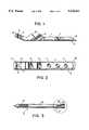
- FIG. 1is a side view and part section of the connector plate
- FIG. 2is a plan view of the connector plate illustrated in FIG. 1,
- FIG. 3is a side view of a long screw
- FIG. 4is a section through the outer end of the screw illustrated in FIG. 3,
- FIG. 5is an end view of the screw illustrated in FIG. 3,
- FIG. 6is a longitudinal section of the sleeve covering the outer end of the long screw
- FIG. 7is a side view and part section of the long screw positioned in the sleeve of FIG. 6,
- FIG. 7ais an enlarged section of part of screw II and sleeve III
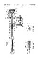
- FIG. 8is a sectional view of the connector plate, the connector arm and auxiliary equipment at the beginning of an operation
- FIG. 9is an end view of the connector arm along line 9--9.
- FIG. 10is a sectional view of the connector plate, the connector arm, and the screwdriver, showing an advanced state of the operation, with one long screw and sleeve position and a second screw in its way to its final position
- FIG. 10ais a longitudinal section of the second removable tube and the drill inserted in the main sleeve
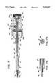
- FIG. 11is a longitudinal section through the screwdriver used in inserting the long screws and their sleeves
- FIG. 11ais an enlarged section of the left hand end of the screwdriver of FIG. 11,
- FIG. 11bis an end view of the screwdriver of FIG. 11,
- FIG. 12is a drawing showing a stage of the operation while using a rod-shaped aiming device
- FIG. 13is a side view and part section of a second embodiment of the connector plate
- FIG. 14is a plan view of the connector plate illustrated in FIG. 13,
- FIG. 15is a section along line 15--15 of FIG. 14,
- FIG. 16is a section along line 16--16 of FIG. 8, showing connection of the connector plate of FIG. 13 to the connector arm,
- FIG. 17is a longitudinal section of another embodiment of the screwdriver illustrated in FIG. 11,
- FIG. 17ais an enlarged section of the left hand end of the screwdriver of FIG. 17,
- FIG. 17bis an end view of the screwdriver of FIG. 17.
- the connector plate I illustrated in FIGS. 1 and 2includes a straight lower, main portion 1 and a head portion 2 outwardly bent in respect of the main portion, to conform to the contour of the bone.
- the head portioncontains one larger, screw-threaded bore 3 and two smaller bores 4 for connection to the horizontal portion of the connector arm as will be described in detail further on.
- screw-threaded bores 5penetrate the main portion at an angle of about 130°, the outer surface of the portion being thickened by two lugs 6 permitting a greater length of the bores 5.
- Underneath the two bores 5three countersunk bores 7 are drilled through the main portion at right angles thereto.
- the lower end of the main portionis sharpened (8) having the purpose of penetrating through the soft tissue and muscles close to the femur shaft during its insertion through a small cut in the skin.
- FIGS. 3 through 7One of the two long screws II and its sleeve III is illustrated in FIGS. 3 through 7:
- the screwincludes a relatively long shaft 10, an inner end provided with screw thread 11 similar to that provided on wood screws, and an outer end recessed in the form of a hexagon 12 continued with a screw-threaded bore 13 of smaller diameter.
- the outer end of the screwis slidably, but tightly, inserted into the inner bore of a sleeve 14, which has its outer end provided with outside screw thread 15 and slotted by two or four slots 16 serving to engage the special screw driver to be shown in FIG. 11.
- the assembled screw and sleeveare shown in FIG. 7, part in side view and part in section.
- the inner end of the sleeveis inwardly crimped (18), thereby preventing the screw from sliding out of the sleeve by contact with a step 17 on the screw shaft.
- the three screws connecting the plate to the shaft of the femur by means of the three bores 7,are not shown as of the usual kind and size used in similar operations.
- FIGS. 8, 9 and 10illustrate the auxiliary equipment serving for insertion and tightening of the long screws and for compressing the fractured bone parts after insertion of the screws.
- the main instrumentis an L-shaped connector arm IV which includes a horizontal portion 20 and a vertical portion 21 firmly connected to each other at right angles.
- the horizontal portionis provided at its inner end with two pins (not visible) engaging the bores 4 of the connector plate and serving to ensure exact parallel alignment of the connector plate with the vertical portion.
- a connecting screw 22extends through a central bore in the horizontal portion and connects the connector arm to the plate by engaging the screw thread 3 in the latter, being actuated by a grip 23. At the same time two pins enter the bores 4 and prevent relative rotation of connector plate and arm.
- the screw 22is hollow to permit passage of a long, pointed bar 24 provided with a grip 25 for forceful insertion into the bone and for exact location of both the connector plate and the connector arm relative to the femur bone.
- the vertical portioncontains two large, obliquely directed bores 26 which are coaxially aligned with the bores 5 in the connector plate, but of larger diameter, Above the two bores 26, three smaller bores 27 are drilled through the portion at right angles thereto and coaxially aligned with the bores 7 of the connector plate, Set screws 28 penetrate the sides of the bores 26 and 27 and serve to hold the tubular guides in position.
- An additional feature of the connector armis in the form of an oblong hole 29 perforating the lower end of tile vertical portion and adapted to hold a rod-shaped aiming device which is secured by a set screw 28'.
- FIG. 12shows the aiming device in position, as well as the X-ray equipment positioned above and below the fracture to be connected.
- FIG. 8likewise illustrates a first stage of an operation carried out by means of the device: after the connector plate has been inserted into the thigh through a small cut and has been slid into an approximate position as viewed by means of X-ray equipment and the aiming device; its correct location in relation to the neck portion is found by means of a guide wire 30 which is inserted into the bone material of the femur shaft and into the bone of the neck through an inner tubular guide (32) located within an outer tube 31 extending through the bore 26 of the connector arm into the screw-threaded bore 5 of the connector plate, The inner tubular guide 32 is screwed into bore 5 of the plate in order to permit exact centering of guide wire 30 and to prevent its disengagement from the connector plate, In case of incorrect location the guide wire is withdrawn, the connector plate is moved by means of the connector arm into another position and the guide wire is again inserted into the bone.
- a guide wire 30which is inserted into the bone material of the femur shaft and into the bone of the neck through an inner
- the pointed bar 24is forcefully pushed into the bone to finally fix the position of bone and plate, whereupon the guide wire 30 and the inner tubular guide (32) are removed. They are replaced by the second inner tubular guide 32a of wider inner bore, and a drill 35 is inserted therethrough which, by mechanical rotation, drills holes into the shaft and the neck for subsequent insertion of one of the long screws.
- the special screwdriver V as illustrated in FIG. 11comprises three concentrically aligned shafts which are independently movable in both axial and rotary direction. They include:
- an inner tubular shaft 43having a hexagon-shaped end 44 for engagement with the hexagonal recess 12 in the long screws. It can be rotated for driving the screw into the pre-drilled bone material by means of a cylindrical grip 45 via a disc 46 firmly mounted on the shaft 43.
- An outermost tubular shaft 47having an inner end in the form of cross-wise aligned edges 48 for engagement with slots 16 in the screw sleeves III. It can be rotated for the purpose of screwing the sleeves into the connector plate by means of a cylindrical grip 49.
- An outer sleeve 56rotationally and longitudinally movable on the inner movable shaft 43. It is provided with a circumferential recess 58 engaged by a pin 59 serving to limit the longitudinal motion of the shaft. A second circumferential recess is provided at the other end of sleeve 56 and engages a stop 57.
- the componentscan be axially moved relative to each other, but are urged into their normal position by helical springs 50 and 51, while additional axial motion of the tubular shaft 43 is made possible by withdrawal of stop 57; their specific use will be explained further on in connection with the final stage of the operation.
- FIG. 10The final stage of the operation of connecting a fractured head to the femur shaft is illustrated in FIG. 10, as follows:
- the inner tubular guideis removed.
- the two long screw-and-sleeve assembliesare inserted and fastened, one after the other, with the aid of the screw driver V, as follows: a screw II is pulled back into a sleeve III up to its outer end, and the hexagon-shaped end 44 of the screwdriver is pushed into the correspondingly shaped recess 12 in the screw end.
- screw IIBy rotating and pushing grip 45 inwardly, screw II is moved along sleeve III and is urged towards the fractured head portion and inserted into the pre-drilled bore in the bone material, rotation being stopped as soon as it has reached the required depth as viewed by X-ray equipment, or whenever step 17 on the screw has reached the crimped end 18 of the sleeve.
- a pin 60 engaging with a circumferential groove 61limits the distance to which grip 42 can be moved in an outward direction, while being urged there by spring 51.
- fracture compression pin 60transfers the load from grip 45 to shaft 40 via grip 42.
- a retracting device VIis attached to the grips 45 and 49 by means of pins 52 inserted into corresponding holes 53.
- screw 55pulls grips 49 and 45 apart as well as grip 42 (by means of pin 60),thereby pulling the attached screw II into the sleeve which is firmly screwed and secured in the plate.
- pointed bar 24is removed and the second screw is inserted into the fractured parts in the same manner.
- FIGS. 13, 14, 15 and 16show a simplified version of the connector plate illustrated in FIGS. 1 and 2.
- the present connector platehas a thicker upper portion, while the lower portion is of about the same thickness as that shown in FIG. 1. Instead of the bent head portion the underside of the thickened upper portion is cut away at a slant (102) corresponding to the shape of the femur.
- the two lugs 6 appearing in FIG. 1are necessary to permit a sufficient length of the screw thread 5, but owing to the greater thickness of the present plate there is sufficient material for these bores.
- FIG. 17A second version of the screwdriver V is illustrated in FIG. 17, wherein the means for moving the grips 49a and 45a apart is by means of a cup-shaped spacer 62.
- the spaceris provided with an inner screw-thread cooperating with an outer screw-thread on grip 49a.
- By rotation of the spacerit is moved to the rear until it contacts grip 45a and moves grip 42 via pin 60 to the rear, thereby pulling screw II rearwardly into the sleeve by means of screw 41 engaging the tapped bore 13 in the screw end, and thus compresses the fracture.
- FIG. 12illustrates the shape and use of an aiming device which is an additional feature of the invention.
- the deviceis used at the beginning of the operation to locate the optimal final position of the screws to be inserted into the fractured bone. It is attached to the connector arm 21 and is adjusted in the direction of the fracture from the outside of the thigh. By viewing the position of the aiming device in relation to the femoral neck by X-ray equipment (73,74) the position of the connector plate and the auxiliary equipment can be adjusted and brought into the most suitable location.
- the aiming devicecomprises an aiming rod 70 connected to the end of a connecting bar 71 at right angles by clamping means 72.
- the connecting baris held in position in the hole 29 at the bottom end of the connector arm 21 and secured there by means of the set screw 28'. After adjustment of the connector plate the aiming device can be detached. As known to the art, all further stages of the operation are likewise controlled by X-ray viewing.
Landscapes
- Health & Medical Sciences (AREA)
- Life Sciences & Earth Sciences (AREA)
- Orthopedic Medicine & Surgery (AREA)
- Surgery (AREA)
- Medical Informatics (AREA)
- General Health & Medical Sciences (AREA)
- Biomedical Technology (AREA)
- Heart & Thoracic Surgery (AREA)
- Nuclear Medicine, Radiotherapy & Molecular Imaging (AREA)
- Molecular Biology (AREA)
- Animal Behavior & Ethology (AREA)
- Engineering & Computer Science (AREA)
- Public Health (AREA)
- Veterinary Medicine (AREA)
- Dentistry (AREA)
- Oral & Maxillofacial Surgery (AREA)
- Neurology (AREA)
- Surgical Instruments (AREA)
Abstract
Description
Claims (16)
Applications Claiming Priority (3)
| Application Number | Priority Date | Filing Date | Title |
|---|---|---|---|
| IL105183 | 1993-03-28 | ||
| IL10518393AIL105183A (en) | 1993-03-28 | 1993-03-28 | Surgical device for connection of fractured bones |
| JP23904994AJP3532622B2 (en) | 1993-03-28 | 1994-10-03 | Surgical instruments for percutaneous connection |
Publications (1)
| Publication Number | Publication Date |
|---|---|
| US5429641Atrue US5429641A (en) | 1995-07-04 |
Family
ID=26322603
Family Applications (1)
| Application Number | Title | Priority Date | Filing Date |
|---|---|---|---|
| US08/170,529Expired - LifetimeUS5429641A (en) | 1993-03-28 | 1993-12-20 | Surgical device for connection of fractured bones |
Country Status (3)
| Country | Link |
|---|---|
| US (1) | US5429641A (en) |
| EP (1) | EP0617927B1 (en) |
| IL (1) | IL105183A (en) |
Cited By (180)
| Publication number | Priority date | Publication date | Assignee | Title |
|---|---|---|---|---|
| US5741262A (en)* | 1992-02-28 | 1998-04-21 | Astra Aktiebolag | Hip joint prosthesis |
| US5741266A (en)* | 1996-09-19 | 1998-04-21 | Biomet, Inc. | Pin placement guide and method of making a bone entry hole for implantation of an intramedullary nail |
| US5836950A (en)* | 1994-11-22 | 1998-11-17 | Hansson; Henrik Lars Johan | Guide instrument |
| US5849004A (en)* | 1996-07-17 | 1998-12-15 | Bramlet; Dale G. | Surgical anchor |
| RU2151566C1 (en)* | 1999-03-31 | 2000-06-27 | Учебно-научный центр Медицинского центра Управления делами Президента Российской Федерации | Device for carrying out osteosynthesis of fractured proximal segment of the femur |
| RU2152763C1 (en)* | 1999-09-01 | 2000-07-20 | Кемеровская городская клиническая больница N 3 им.М.А. Подгорбунского | Method for performing osteosynthesis using wires |
| US6183477B1 (en) | 1998-09-04 | 2001-02-06 | Smith & Nephew, Inc. | Attachment tool for drill guide |
| US6231611B1 (en)* | 1996-06-14 | 2001-05-15 | Raphael Mosseri | Total hip prosthesis for endo-articular implantation, and ancillary device therefor |
| US6342057B1 (en) | 2000-04-28 | 2002-01-29 | Synthes (Usa) | Remotely aligned surgical drill guide |
| US6379364B1 (en) | 2000-04-28 | 2002-04-30 | Synthes (Usa) | Dual drill guide for a locking bone plate |
| US6447546B1 (en) | 2000-08-11 | 2002-09-10 | Dale G. Bramlet | Apparatus and method for fusing opposing spinal vertebrae |
| US20020156474A1 (en)* | 2001-04-20 | 2002-10-24 | Michael Wack | Polyaxial locking plate |
| US20030004513A1 (en)* | 2001-06-27 | 2003-01-02 | Guzman Pamela C. | Method and apparatus for use in the performance of endoscopic minimally invasive orthopaedic plating procedures |
| EP1279373A2 (en) | 2001-07-26 | 2003-01-29 | Yechiel Gotfried | Screwdriver used with a bone connector plate |
| US20030040752A1 (en)* | 2001-08-21 | 2003-02-27 | Kitchens David Gregory | Method and apparatus for percutaneously securing a bone screw and a bone plate to a bone of a patient |
| US20030074005A1 (en)* | 2001-10-17 | 2003-04-17 | Roth Christoph A. | Orthopedic implant insertion instruments |
| US6554553B2 (en) | 1993-03-23 | 2003-04-29 | Yosef Freedland | Tension adjusting device |
| US6589242B1 (en)* | 2000-10-20 | 2003-07-08 | Frederic C. Feiler | Percutaneous scaphoid fixation method and device |
| US20030135211A1 (en)* | 2002-01-17 | 2003-07-17 | Cho Woo Shin | Intramedullary nail, device for inserting a screw into the same and method thereof |
| US6623486B1 (en) | 1999-09-13 | 2003-09-23 | Synthes (U.S.A.) | bone plating system |
| US20030187447A1 (en)* | 2001-04-16 | 2003-10-02 | Joseph Ferrante | Orthopedic screw and method of use |
| US20030220641A1 (en)* | 2000-03-07 | 2003-11-27 | Thelen Sarah L. | Method and apparatus for reducing femoral fractures |
| US6702824B2 (en) | 1999-09-10 | 2004-03-09 | Depuy Orthopaedics, Inc. | Prosthesis positioning apparatus |
| US20040147937A1 (en)* | 2003-01-24 | 2004-07-29 | Depuy Spine, Inc. | Spinal rod approximators |
| US20040147936A1 (en)* | 2003-01-28 | 2004-07-29 | Rosenberg William S. | Spinal rod approximator |
| WO2004110292A2 (en) | 2003-06-12 | 2004-12-23 | Disc-O-Tech Medical Technologies, Ltd. | Plate device |
| US20040267275A1 (en)* | 2003-06-26 | 2004-12-30 | Cournoyer John R. | Spinal implant holder and rod reduction systems and methods |
| USRE38684E1 (en) | 1997-07-01 | 2005-01-04 | Synthes Ag Chur | Freely separable surgical drill guide and plate |
| US20050015092A1 (en)* | 2003-07-16 | 2005-01-20 | Rathbun David S. | Plating system with multiple function drill guide |
| US20050027301A1 (en)* | 2003-08-01 | 2005-02-03 | Pascal Stihl | Drill guide assembly for a bone fixation device |
| WO2004045384A3 (en)* | 2002-11-19 | 2005-02-03 | Acumed Llc | Guide system for bone-repair devices |
| US20050043738A1 (en)* | 2003-08-19 | 2005-02-24 | Ryan Christopher J. | Spring-loaded awl |
| US20050049594A1 (en)* | 2001-04-20 | 2005-03-03 | Wack Michael A. | Dual locking plate and associated method |
| US20050059969A1 (en)* | 2003-09-17 | 2005-03-17 | Depuy Acromed, Inc. | Rod approximator |
| US20050065532A1 (en)* | 2001-09-27 | 2005-03-24 | Matthias Honl | Surgical instruments |
| US20050101959A1 (en)* | 2000-11-22 | 2005-05-12 | Milorad Mitkovic | Internal fixator of bones |
| DE10348932A1 (en)* | 2003-10-18 | 2005-05-25 | Intercus Gmbh | System for the minimally invasive treatment of a fracture of a bone, in particular a porcimal humeral or femoral fracture |
| RU2254089C2 (en)* | 2003-02-03 | 2005-06-20 | Кемеровская городская клиническая больница №3 им. М.А. Подгорбунского | Fixing member for performing osteosynthesis |
| US20050149036A1 (en)* | 2003-12-17 | 2005-07-07 | Varieur Michael S. | Instruments and methods for bone anchor engagement and spinal rod reduction |
| US20050277937A1 (en)* | 2004-06-10 | 2005-12-15 | Leung Takkwong R | Bone plating system |
| US20060009771A1 (en)* | 2000-02-01 | 2006-01-12 | Orbay Jorge L | Bone stabilization system including plate having fixed-angle holes together with unidirectional locking screws and surgeon-directed locking screws |
| US20060041260A1 (en)* | 2000-02-01 | 2006-02-23 | Orbay Jorge L | Fixation system with plate having holes with divergent axes and multidirectional fixators for use therethrough |
| US20060064106A1 (en)* | 2004-09-23 | 2006-03-23 | Fernandez Alberto A | Coplanar X-ray guided aiming arm for locking of intramedullary nails |
| US20060079909A1 (en)* | 2003-12-17 | 2006-04-13 | Runco Thomas J | Instruments and methods for bone anchor engagement and spinal rod reduction |
| US20060095044A1 (en)* | 2004-11-03 | 2006-05-04 | Grady Mark P Jr | Aiming arm for bone plates |
| US20060155282A1 (en)* | 2003-02-28 | 2006-07-13 | Silvana Vese | Osteosynthesis plate |
| US20060173458A1 (en)* | 2004-10-07 | 2006-08-03 | Micah Forstein | Bone fracture fixation system |
| US7097654B1 (en) | 2000-01-03 | 2006-08-29 | Yosef Freedland | Flip-wing tissue retainer |
| US20060217722A1 (en)* | 2003-09-08 | 2006-09-28 | Christof Dutoit | Bone-fixation device |
| US20060217717A1 (en)* | 2005-03-24 | 2006-09-28 | Dale Whipple | Methods and devices for stabilizing a bone anchor |
| US20060235400A1 (en)* | 2003-08-26 | 2006-10-19 | Rolf Schneider | Bone plate |
| US20060241622A1 (en)* | 2003-06-13 | 2006-10-26 | Zergiebel Earl M | Multiple member interconnect for surgical instrument and absorbable screw fastener |
| US20070016205A1 (en)* | 2003-10-30 | 2007-01-18 | Florian Beutter | Bone plate |
| US7207995B1 (en)* | 2004-01-29 | 2007-04-24 | Biomer Manufacturing Corp. | Method and apparatus for retaining a guide wire |
| US20070118146A1 (en)* | 2005-11-23 | 2007-05-24 | Stryker Trauma S.A. | Compression instrument |
| US7229445B2 (en) | 2004-06-21 | 2007-06-12 | Synthes (Usa) | Bone plate with bladed portion |
| US20070161998A1 (en)* | 2005-10-28 | 2007-07-12 | Dale Whipple | Instruments and Methods For Manipulating A Spinal Rod |
| US20070162015A1 (en)* | 1998-03-31 | 2007-07-12 | Zimmer Technology, Inc. | Orthopaedic bone plate |
| US20070260261A1 (en)* | 2005-06-02 | 2007-11-08 | Depuy Spine, Inc. | Instruments and methods for manipulating a spinal fixation element |
| US20070270845A1 (en)* | 2003-09-08 | 2007-11-22 | Kohsuke Watanabe | Orthopaedic plate and screw assembly |
| US20070299447A1 (en)* | 2003-09-08 | 2007-12-27 | Kohsuke Watanabe | Orthopaedic plate and screw assembly |
| US20080004623A1 (en)* | 2003-09-08 | 2008-01-03 | Joseph Ferrante | Orthopaedic Implant and Screw Assembly |
| US7316687B2 (en)* | 2001-08-24 | 2008-01-08 | Zimmer Technology, Inc. | Blade plate and instruments |
| US20080039851A1 (en)* | 2004-03-25 | 2008-02-14 | Schulz Kurt S | Device and template for canine humeral slide osteotomy |
| US7357804B2 (en) | 2003-08-13 | 2008-04-15 | Synthes (U.S.A.) | Quick-release drill-guide assembly for bone-plate |
| US20080140130A1 (en)* | 2004-01-26 | 2008-06-12 | Chan Jason S | Highly-versatile variable-angle bone plate system |
| US20080140127A1 (en)* | 2006-12-06 | 2008-06-12 | Amei Technologies, Inc. | Volar plate fixation device |
| US20080243190A1 (en)* | 2007-03-29 | 2008-10-02 | Depuy Spine, Inc. | In-line rod reduction device and methods |
| US20080269752A1 (en)* | 2007-04-19 | 2008-10-30 | Stryker Trauma Gmbh | Hip fracture device with barrel and end cap for load control |
| US20080269768A1 (en)* | 2007-04-10 | 2008-10-30 | Stryker Trauma Sa | Bone screw holding device |
| US20080269807A1 (en)* | 2007-04-19 | 2008-10-30 | Stryker Trauma Gmbh | Hip fracture device with static locking mechanism allowing compression |
| US20080281330A1 (en)* | 2005-03-17 | 2008-11-13 | Ferrante Joseph M | Medical Securing Member Placement System |
| US20080281331A1 (en)* | 2007-02-08 | 2008-11-13 | Zimmer, Inc. | Targeting device |
| US20080281326A1 (en)* | 2007-03-20 | 2008-11-13 | Kohsuke Watanabe | Orthopaedic plate and screw assembly |
| US20080281336A1 (en)* | 2003-06-13 | 2008-11-13 | Zergiebel Earl M | Multiple member interconnect for surgical instrument and absorbable screw fastener |
| US20090030419A1 (en)* | 2007-07-26 | 2009-01-29 | Depuy Spine, Inc. | Spinal rod reduction instruments and methods for use |
| US7488327B2 (en)* | 2004-04-12 | 2009-02-10 | Synthes (U.S.A.) | Free hand drill guide |
| US20090088804A1 (en)* | 2007-09-27 | 2009-04-02 | Depuy Products, Inc. | Plate holder assembly having movable guide component |
| US20090088764A1 (en)* | 2007-09-28 | 2009-04-02 | Depuy Spine, Inc. | Dual pivot instrument for reduction of a fixation element and method of use |
| US20090088767A1 (en)* | 2007-09-27 | 2009-04-02 | Depuy Products, Inc. | Guide assembly for use in a medical procedure |
| US20090143825A1 (en)* | 2007-11-30 | 2009-06-04 | Robert Graham | Distal Tibia Plating System |
| US20090171400A1 (en)* | 2007-12-28 | 2009-07-02 | Ross Creek Medical | Apparatus for discrete tissue anchoring for soft tissue repair and method of use |
| US7578825B2 (en) | 2004-04-19 | 2009-08-25 | Acumed Llc | Placement of fasteners into bone |
| US20090281545A1 (en)* | 2008-03-05 | 2009-11-12 | Allston J. Stubbs | Method and Apparatus for Arthroscopic Assisted Arthroplasty of the Hip Joint |
| US7655029B2 (en) | 2001-05-28 | 2010-02-02 | Synthes Usa, Llc | Bone plate |
| US7670341B2 (en) | 2005-12-16 | 2010-03-02 | Depuy Products, Inc. | Orthopaedic device with locking barrel |
| US20100063542A1 (en)* | 2008-09-08 | 2010-03-11 | Van Der Burg Erik | Knotless suture anchor for soft tissue repair and method of use |
| US20100076496A1 (en)* | 2004-01-26 | 2010-03-25 | Alberto Angel Fernandez | Variable Angle Locked Bone Fixation System |
| US20100076503A1 (en)* | 2007-02-07 | 2010-03-25 | N.M.B. Medical Applications Ltd | Bone implant |
| US20100106196A1 (en)* | 2008-10-24 | 2010-04-29 | Paul Lawrence Erickson | Method and system for attaching a plate to a bone |
| US20100121348A1 (en)* | 2008-11-12 | 2010-05-13 | Ross Creek Medical | Insertion tool for knotless suture anchor for soft tissue repair and method of use |
| US20100204798A1 (en)* | 2005-10-21 | 2010-08-12 | Stryker Spine | System and method for fusion cage implantation |
| US7780664B2 (en) | 2002-12-10 | 2010-08-24 | Depuy Products, Inc. | Endosteal nail |
| US7896886B2 (en) | 2005-01-28 | 2011-03-01 | Depuy Products, Inc. | Nail plate and implantation jig therefor |
| US7905910B2 (en) | 2003-09-29 | 2011-03-15 | Smith & Nephew, Inc. | Bone plates and bone plate assemblies |
| US7905909B2 (en) | 2005-09-19 | 2011-03-15 | Depuy Products, Inc. | Bone stabilization system including multi-directional threaded fixation element |
| US7938850B2 (en) | 2002-05-30 | 2011-05-10 | Depuy Products, Inc. | Nail plate |
| US7951176B2 (en) | 2003-05-30 | 2011-05-31 | Synthes Usa, Llc | Bone plate |
| US8105367B2 (en) | 2003-09-29 | 2012-01-31 | Smith & Nephew, Inc. | Bone plate and bone plate assemblies including polyaxial fasteners |
| RU2446767C2 (en)* | 2010-06-02 | 2012-04-10 | Евгений Петрович Костив | Methods of osteosynthesis of femur neck fractures and device for its realisation |
| US8206394B2 (en) | 2009-05-13 | 2012-06-26 | Depuy Spine, Inc. | Torque limited instrument for manipulating a spinal rod relative to a bone anchor |
| US8257439B2 (en) | 2004-12-22 | 2012-09-04 | Ldr Medical | Intervertebral disc prosthesis |
| US8262709B1 (en)* | 2011-09-24 | 2012-09-11 | Powlan Roy Y | Device and method for femoral neck fracture fixation |
| US8267999B2 (en) | 2002-11-05 | 2012-09-18 | Ldr Medical | Intervertebral disc prosthesis |
| US8303601B2 (en) | 2006-06-07 | 2012-11-06 | Stryker Spine | Collet-activated distraction wedge inserter |
| US8343219B2 (en) | 2007-06-08 | 2013-01-01 | Ldr Medical | Intersomatic cage, intervertebral prosthesis, anchoring device and implantation instruments |
| US8382807B2 (en) | 2005-07-25 | 2013-02-26 | Smith & Nephew, Inc. | Systems and methods for using polyaxial plates |
| US8409288B2 (en) | 2006-02-15 | 2013-04-02 | Ldr Medical | Transforaminal intersomatic cage for an intervertebral fusion graft and an instrument for implanting the cage |
| US8425574B2 (en) | 2002-07-22 | 2013-04-23 | Acumed, Llc | Bone fixation with a bone plate attached to a fastener assembly |
| US8439932B2 (en) | 2010-05-03 | 2013-05-14 | Biomet Manufacturing Corp. | Submuscular plating system |
| US8449544B2 (en) | 2009-06-30 | 2013-05-28 | Smith & Nephew, Inc. | Orthopaedic implant and fastener assembly |
| US8465546B2 (en) | 2007-02-16 | 2013-06-18 | Ldr Medical | Intervertebral disc prosthesis insertion assemblies |
| US8535322B1 (en)* | 2012-11-07 | 2013-09-17 | Roy Y. Powlan | Hip nail and inertial insertion tooling |
| US20130310842A1 (en)* | 2012-05-15 | 2013-11-21 | Tobias Winkler | Installation tool for bone screw |
| US8608746B2 (en) | 2008-03-10 | 2013-12-17 | DePuy Synthes Products, LLC | Derotation instrument with reduction functionality |
| US8709044B2 (en) | 2005-03-04 | 2014-04-29 | DePuy Synthes Products, LLC | Instruments and methods for manipulating vertebra |
| US8709015B2 (en) | 2008-03-10 | 2014-04-29 | DePuy Synthes Products, LLC | Bilateral vertebral body derotation system |
| US8758346B2 (en) | 2009-09-14 | 2014-06-24 | DePuy Synthes Products, LLC | Variable angle compression plate |
| US20140180342A1 (en)* | 2012-08-30 | 2014-06-26 | Wright Medical Technology, Inc. | Implant for osteotomy, tool for inserting the implant, and method of inserting the implant using the tool |
| US8771284B2 (en) | 2005-11-30 | 2014-07-08 | Ldr Medical | Intervertebral disc prosthesis and instrumentation for insertion of the prosthesis between the vertebrae |
| CN103945781A (en)* | 2011-11-18 | 2014-07-23 | 新特斯有限责任公司 | Femoral neck fracture implant |
| US20140207196A1 (en)* | 2013-01-22 | 2014-07-24 | Paul Slagle | Limited Collapse Surgical Screws |
| US20140243826A1 (en)* | 2013-02-28 | 2014-08-28 | Yechiel Gotfried | Method for connecting fractured bone |
| US8834469B2 (en) | 2009-06-30 | 2014-09-16 | Smith & Nephew, Inc. | Orthopaedic implant and fastener assembly |
| USD714938S1 (en)* | 2013-08-01 | 2014-10-07 | Yechiel Gotfried | Surgical nail |
| US8858635B2 (en) | 2004-02-04 | 2014-10-14 | Ldr Medical | Intervertebral disc prosthesis |
| US8940028B2 (en) | 2005-07-25 | 2015-01-27 | Smith & Nephew, Inc. | Systems and methods for using polyaxial plates |
| US8974532B2 (en) | 2004-04-28 | 2015-03-10 | Ldr Medical | Intervertebral disc prosthesis |
| US8979932B2 (en) | 2005-09-23 | 2015-03-17 | Ldr Medical | Intervertebral disc prosthesis |
| US9039774B2 (en) | 2012-02-24 | 2015-05-26 | Ldr Medical | Anchoring device and system for an intervertebral implant, intervertebral implant and implantation instrument |
| US9044337B2 (en) | 2009-12-31 | 2015-06-02 | Ldr Medical | Anchoring device and system for an intervertebral implant, intervertebral implant and implantation instrument |
| US9078765B2 (en) | 2001-07-13 | 2015-07-14 | Ldr Medical | Vertebral cage device with modular fixation |
| US9095379B2 (en) | 2005-03-04 | 2015-08-04 | Medos International Sarl | Constrained motion bone screw assembly |
| US9333095B2 (en) | 2001-05-04 | 2016-05-10 | Ldr Medical | Intervertebral disc prosthesis, surgical methods, and fitting tools |
| US9408646B2 (en) | 2003-09-03 | 2016-08-09 | DePuy Synthes Products, Inc. | Bone plate with captive clips |
| US9414870B2 (en) | 2003-09-03 | 2016-08-16 | DePuy Synthes Products, Inc. | Translatable carriage fixation system |
| US9463091B2 (en) | 2009-09-17 | 2016-10-11 | Ldr Medical | Intervertebral implant having extendable bone fixation members |
| US9468479B2 (en) | 2013-09-06 | 2016-10-18 | Cardinal Health 247, Inc. | Bone plate |
| US20170007303A1 (en)* | 2014-02-12 | 2017-01-12 | Swemac Innovation Ab | Targeting device and method |
| US9566078B2 (en) | 2012-01-19 | 2017-02-14 | Stryker European Holdings I, Llc | Guide sleeve for suprapatellar surgery |
| US9636228B2 (en) | 2007-02-10 | 2017-05-02 | Howmedica Osteonics Corp. | Radial head implant |
| US9655726B2 (en) | 2004-12-01 | 2017-05-23 | Mayo Foundation For Medical Research And Education | Radial-capitellar implant |
| US20180221074A1 (en)* | 2012-12-28 | 2018-08-09 | Paragon 28, Inc. | Alignment guide apparatus, methods and systems |
| CN108420523A (en)* | 2018-04-20 | 2018-08-21 | 杭州三坛医疗科技有限公司 | Fracture of neck of femur hollow screw guider |
| US20180344331A1 (en)* | 2014-06-30 | 2018-12-06 | Tornier, Inc. | Device for maintaining alignment of a cannulated shaft over a guide pin |
| US10201358B2 (en) | 2015-04-21 | 2019-02-12 | Acumed Llc | Articulating syndesmosis targeting guide device and method |
| CN109640791A (en)* | 2016-08-24 | 2019-04-16 | 克瑞肖株式会社 | Medical probe |
| US10390866B2 (en) | 2011-06-15 | 2019-08-27 | Smith & Nephew, Inc. | Variable angle locking implant |
| US10603185B2 (en) | 2004-02-04 | 2020-03-31 | Ldr Medical | Intervertebral disc prosthesis |
| US10624686B2 (en) | 2016-09-08 | 2020-04-21 | DePuy Synthes Products, Inc. | Variable angel bone plate |
| CN111281515A (en)* | 2020-02-25 | 2020-06-16 | 自贡市第四人民医院(自贡市急救中心) | An auxiliary tool for fracture fixation |
| US10772665B2 (en) | 2018-03-29 | 2020-09-15 | DePuy Synthes Products, Inc. | Locking structures for affixing bone anchors to a bone plate, and related systems and methods |
| US10820930B2 (en) | 2016-09-08 | 2020-11-03 | DePuy Synthes Products, Inc. | Variable angle bone plate |
| US10905476B2 (en) | 2016-09-08 | 2021-02-02 | DePuy Synthes Products, Inc. | Variable angle bone plate |
| US10925651B2 (en) | 2018-12-21 | 2021-02-23 | DePuy Synthes Products, Inc. | Implant having locking holes with collection cavity for shavings |
| US10973556B2 (en) | 2008-06-17 | 2021-04-13 | DePuy Synthes Products, Inc. | Adjustable implant assembly |
| US10993750B2 (en) | 2015-09-18 | 2021-05-04 | Smith & Nephew, Inc. | Bone plate |
| US11013541B2 (en) | 2018-04-30 | 2021-05-25 | DePuy Synthes Products, Inc. | Threaded locking structures for affixing bone anchors to a bone plate, and related systems and methods |
| US11026727B2 (en) | 2018-03-20 | 2021-06-08 | DePuy Synthes Products, Inc. | Bone plate with form-fitting variable-angle locking hole |
| CN113116490A (en)* | 2021-04-13 | 2021-07-16 | 上海市第六人民医院 | Internal fixator and auxiliary device for femoral neck fracture |
| US11213303B2 (en)* | 2014-09-12 | 2022-01-04 | Innovision, Inc. | Bone drill guides and methods of use thereof |
| US11259851B2 (en) | 2003-08-26 | 2022-03-01 | DePuy Synthes Products, Inc. | Bone plate |
| US11291484B2 (en) | 2004-01-26 | 2022-04-05 | DePuy Synthes Products, Inc. | Highly-versatile variable-angle bone plate system |
| US11291481B2 (en) | 2019-03-21 | 2022-04-05 | Medos International Sarl | Rod reducers and related methods |
| US11291482B2 (en) | 2019-03-21 | 2022-04-05 | Medos International Sarl | Rod reducers and related methods |
| US11382674B2 (en)* | 2016-10-05 | 2022-07-12 | Arthrex, Inc. | Fifth metatarsal repair systems and methods of use |
| US11559316B2 (en) | 2017-07-11 | 2023-01-24 | Paragon 28, Inc. | Bone fixation system, assembly, implants, devices, insertion guides, and methods of use |
| US11642142B2 (en) | 2016-10-24 | 2023-05-09 | Paragon 28, Inc. | Osteotomy systems, devices and methods |
| US11666345B2 (en) | 2017-02-27 | 2023-06-06 | Paragon 28, Inc. | Intramedullary nail alignment guides, fixation guides, devices, systems, and methods of use |
| US11779381B2 (en) | 2017-03-30 | 2023-10-10 | Paragon 28, Inc. | Bone fixation system, assembly, implants, devices, alignment guides, and methods of use |
| US11779358B2 (en) | 2017-02-27 | 2023-10-10 | Paragon 28, Inc. | Targeting instruments, systems and methods of use |
| USD1004774S1 (en) | 2019-03-21 | 2023-11-14 | Medos International Sarl | Kerrison rod reducer |
| US11832855B2 (en) | 2017-12-15 | 2023-12-05 | Medos International Sårl | Unilateral implant holders and related methods |
| RU2812577C1 (en)* | 2023-05-23 | 2024-01-30 | федеральное государственное бюджетное образовательное учреждение высшего образования "Тамбовский государственный университет имени Г.Р. Державина" | Method of osteosynthesis of femoral neck fractures using v-shaped wires |
| US11918261B2 (en) | 2019-04-12 | 2024-03-05 | Stryker European Operations Limited | Locking system for femoral neck fracture fixation |
| US11925364B2 (en) | 2019-02-13 | 2024-03-12 | Paragon 28, Inc. | Implant, alignment guides, system and methods of use |
| WO2024121848A1 (en)* | 2022-12-06 | 2024-06-13 | Medical Research & Development Fund for Health Services Bnai Zion Medical Center | Device, system and method for fixation of fractured bones |
| US12076031B2 (en) | 2019-02-14 | 2024-09-03 | Paragon 28, Inc. | Threaded targeting instruments, systems and methods of use |
| US12171442B2 (en) | 2019-02-28 | 2024-12-24 | Paragon 28, Inc. | Fusion systems, instruments, bone plates and methods of use |
| US12318121B2 (en) | 2020-11-09 | 2025-06-03 | Medos International Sàrl | Biplanar forceps reducers and methods of use |
Families Citing this family (22)
| Publication number | Priority date | Publication date | Assignee | Title |
|---|---|---|---|---|
| IL109929A (en) | 1994-06-08 | 1998-04-05 | Gotfried Yehiel | Surgical instrument for use during connection of a fractured bone |
| EP1099413A1 (en)* | 1999-11-09 | 2001-05-16 | Schlumbohm Medizin-Labor-Technologie GmbH | Aiming device for distal locking of an intramedullary nail |
| US7488329B2 (en) | 2000-03-07 | 2009-02-10 | Zimmer Technology, Inc. | Method and apparatus for reducing femoral fractures |
| US7485119B2 (en) | 2000-03-07 | 2009-02-03 | Zimmer Technology, Inc. | Method and apparatus for reducing femoral fractures |
| DE10131993A1 (en)* | 2001-07-02 | 2003-01-23 | Aesculap Ag & Co Kg | Surgical instrument |
| DE10131992B4 (en)* | 2001-07-02 | 2006-11-16 | Aesculap Ag & Co. Kg | bone plate |
| FR2841459B1 (en) | 2002-06-28 | 2004-08-27 | Sanortho | MINIMALLY INVASIVE OSTEOSYNTHESIS DEVICE, PARTICULARLY HIP SCREWS |
| AU2002340696A1 (en)* | 2002-11-15 | 2004-06-15 | Synthes Ag Chur | Bone plate, especially for fixing fractures of the neck of the femur |
| GB2402883B (en)* | 2003-06-21 | 2006-07-05 | Ravi Kumar Khetrapal | Apparatus for assisted percutaneous fixation |
| EP1750604A1 (en)* | 2004-04-12 | 2007-02-14 | Thakkar Dr. Navin | An implant assembly for proximal femoral fracture |
| US20060229624A1 (en) | 2005-03-31 | 2006-10-12 | Zimmer Technology, Inc. | Orthopaedic cutting instrument and method |
| EP1878393A1 (en)* | 2006-07-10 | 2008-01-16 | Stryker Trauma GmbH | Drill assembly for bone reconstruction plate |
| DE202007007322U1 (en) | 2007-05-23 | 2008-10-02 | Baumgart, Rainer, Prof. Dr.med., Dipl.-Ing. | Set of instruments for the minimally invasive preparation of a bone nailing |
| WO2009013568A1 (en)* | 2007-07-20 | 2009-01-29 | Nilli Del Medico | Surgical device for the connection of fractured bones |
| SE533303C2 (en)* | 2007-07-24 | 2010-08-17 | Henrik Hansson | Device for fixing bone fragments in case of bone fracture |
| ITTO20080845A1 (en)* | 2008-11-17 | 2010-05-18 | Intrauma S R L | INSTRUMENT FOR INSERTION OF DRIVING WIRES IN A FRACTURE BONE. |
| EP2455014B1 (en)* | 2010-11-17 | 2015-08-12 | Hyprevention | Implantable device for preventive or interventive treatment of femur fractures, associated ancillary device |
| CN102836002B (en)* | 2012-09-10 | 2014-12-10 | 苏州大学 | Kirschner wire guiding device |
| US9980760B2 (en)* | 2014-11-19 | 2018-05-29 | Paragon 28, Inc. | Step off bone plates, systems, and methods of use |
| EP3820382B1 (en) | 2018-07-11 | 2025-09-10 | Paragon 28, Inc. | Systems comprising alignment guides and implants |
| RU188428U1 (en)* | 2018-09-25 | 2019-04-11 | Общество С Ограниченной Ответственностью "Сахил" | SCREW FOR OSTEOSYNTHESIS OF THE FEMORAL NECK |
| CN109247986B (en)* | 2018-11-21 | 2020-11-03 | 南方医科大学珠江医院 | Fixing method and device for atlantoaxial dislocation assisting incomplete reduction |
Citations (6)
| Publication number | Priority date | Publication date | Assignee | Title |
|---|---|---|---|---|
| FR2501033A1 (en)* | 1981-03-03 | 1982-09-10 | Letournel Emile | Osteosynthesis plate for lower end of femur - has curved main shaft with boss near lower end above pair of oppositely cambered apertured sections |
| US4465065A (en)* | 1983-01-07 | 1984-08-14 | Yechiel Gotfried | Surgical device for connection of fractured bones |
| CH670125A5 (en)* | 1986-07-11 | 1989-05-12 | Ver Drahtwerke Ag | Two-dia. screw with two threaded portions - has larger thread on sleeve turning but not sliding on shank |
| US4940467A (en)* | 1988-02-03 | 1990-07-10 | Tronzo Raymond G | Variable length fixation device |
| GB2232218A (en)* | 1989-06-02 | 1990-12-05 | Frederick John Yarrow | Security fasteners for preventing theft or vandalism |
| US5176681A (en)* | 1987-12-14 | 1993-01-05 | Howmedica International Inc. | Intramedullary intertrochanteric fracture fixation appliance and fitting device |
Family Cites Families (8)
| Publication number | Priority date | Publication date | Assignee | Title |
|---|---|---|---|---|
| US2834342A (en)* | 1956-08-29 | 1958-05-13 | Clyde E Yost | Surgical device for the fixation of fractured bones |
| US4530355A (en)* | 1982-01-18 | 1985-07-23 | Richards Manufacturing Co., Inc. | Compression screw assembly |
| DE3534747A1 (en)* | 1985-09-28 | 1987-04-09 | Hasselbach Christoph Von | THIGH NECK IMPLANT |
| US4776330A (en)* | 1986-06-23 | 1988-10-11 | Pfizer Hospital Products Group, Inc. | Modular femoral fixation system |
| WO1989006940A1 (en)* | 1988-02-03 | 1989-08-10 | Biomet, Inc. | Variable length fixation device |
| DE8900121U1 (en)* | 1989-01-04 | 1990-02-15 | Mecron Medizinische Produkte Gmbh, 1000 Berlin | Compression screw connection device |
| US5032125A (en)* | 1990-02-06 | 1991-07-16 | Smith & Nephew Richards Inc. | Intramedullary hip screw |
| US5217462A (en)* | 1991-03-05 | 1993-06-08 | Pfizer Hospital Products Group, Inc. | Screw and driver |
- 1993
- 1993-03-28ILIL10518393Apatent/IL105183A/ennot_activeIP Right Cessation
- 1993-12-20USUS08/170,529patent/US5429641A/ennot_activeExpired - Lifetime
- 1994
- 1994-03-24EPEP94302143Apatent/EP0617927B1/ennot_activeExpired - Lifetime
Patent Citations (6)
| Publication number | Priority date | Publication date | Assignee | Title |
|---|---|---|---|---|
| FR2501033A1 (en)* | 1981-03-03 | 1982-09-10 | Letournel Emile | Osteosynthesis plate for lower end of femur - has curved main shaft with boss near lower end above pair of oppositely cambered apertured sections |
| US4465065A (en)* | 1983-01-07 | 1984-08-14 | Yechiel Gotfried | Surgical device for connection of fractured bones |
| CH670125A5 (en)* | 1986-07-11 | 1989-05-12 | Ver Drahtwerke Ag | Two-dia. screw with two threaded portions - has larger thread on sleeve turning but not sliding on shank |
| US5176681A (en)* | 1987-12-14 | 1993-01-05 | Howmedica International Inc. | Intramedullary intertrochanteric fracture fixation appliance and fitting device |
| US4940467A (en)* | 1988-02-03 | 1990-07-10 | Tronzo Raymond G | Variable length fixation device |
| GB2232218A (en)* | 1989-06-02 | 1990-12-05 | Frederick John Yarrow | Security fasteners for preventing theft or vandalism |
Cited By (378)
| Publication number | Priority date | Publication date | Assignee | Title |
|---|---|---|---|---|
| US5741262A (en)* | 1992-02-28 | 1998-04-21 | Astra Aktiebolag | Hip joint prosthesis |
| US6554553B2 (en) | 1993-03-23 | 2003-04-29 | Yosef Freedland | Tension adjusting device |
| US5836950A (en)* | 1994-11-22 | 1998-11-17 | Hansson; Henrik Lars Johan | Guide instrument |
| US6231611B1 (en)* | 1996-06-14 | 2001-05-15 | Raphael Mosseri | Total hip prosthesis for endo-articular implantation, and ancillary device therefor |
| US6482237B2 (en) | 1996-06-14 | 2002-11-19 | Raphael Mosseri | Total hip prosthesis adapted to be implanted endo-articularly and its auxiliary device and method of implantation |
| US5849004A (en)* | 1996-07-17 | 1998-12-15 | Bramlet; Dale G. | Surgical anchor |
| US5895390A (en)* | 1996-09-19 | 1999-04-20 | Biomet, Inc. | Pin placement guide used in making a bone entry hole for implantation of an intramedullary nail |
| US5741266A (en)* | 1996-09-19 | 1998-04-21 | Biomet, Inc. | Pin placement guide and method of making a bone entry hole for implantation of an intramedullary nail |
| USRE38684E1 (en) | 1997-07-01 | 2005-01-04 | Synthes Ag Chur | Freely separable surgical drill guide and plate |
| US20070162015A1 (en)* | 1998-03-31 | 2007-07-12 | Zimmer Technology, Inc. | Orthopaedic bone plate |
| US7846189B2 (en) | 1998-03-31 | 2010-12-07 | Zimmer, Inc. | Orthopaedic bone plate |
| US6183477B1 (en) | 1998-09-04 | 2001-02-06 | Smith & Nephew, Inc. | Attachment tool for drill guide |
| RU2151566C1 (en)* | 1999-03-31 | 2000-06-27 | Учебно-научный центр Медицинского центра Управления делами Президента Российской Федерации | Device for carrying out osteosynthesis of fractured proximal segment of the femur |
| RU2152763C1 (en)* | 1999-09-01 | 2000-07-20 | Кемеровская городская клиническая больница N 3 им.М.А. Подгорбунского | Method for performing osteosynthesis using wires |
| US6702824B2 (en) | 1999-09-10 | 2004-03-09 | Depuy Orthopaedics, Inc. | Prosthesis positioning apparatus |
| US7128744B2 (en) | 1999-09-13 | 2006-10-31 | Synthes (Usa) | Bone plating system |
| US6623486B1 (en) | 1999-09-13 | 2003-09-23 | Synthes (U.S.A.) | bone plating system |
| US9211151B2 (en) | 1999-09-13 | 2015-12-15 | DePuy Synthes Products, Inc. | Bone plating system |
| US20040059335A1 (en)* | 1999-09-13 | 2004-03-25 | Synthes (U.S.A.) | Bone plating system |
| US7341589B2 (en) | 1999-09-13 | 2008-03-11 | Synthes (U.S.A.) | Bone plating system |
| US8641744B2 (en) | 1999-09-13 | 2014-02-04 | DePuy Synthes Products, LLC | Bone plating system |
| US20040059334A1 (en)* | 1999-09-13 | 2004-03-25 | Synthes (U.S.A.) | Bone plating system |
| US20080132960A1 (en)* | 1999-09-13 | 2008-06-05 | Weaver Paul C | Bone Plating System |
| US20050080421A1 (en)* | 1999-09-13 | 2005-04-14 | Synthes (Usa) | Bone plating system |
| US7097654B1 (en) | 2000-01-03 | 2006-08-29 | Yosef Freedland | Flip-wing tissue retainer |
| US7695502B2 (en) | 2000-02-01 | 2010-04-13 | Depuy Products, Inc. | Bone stabilization system including plate having fixed-angle holes together with unidirectional locking screws and surgeon-directed locking screws |
| US20060041260A1 (en)* | 2000-02-01 | 2006-02-23 | Orbay Jorge L | Fixation system with plate having holes with divergent axes and multidirectional fixators for use therethrough |
| US20060009771A1 (en)* | 2000-02-01 | 2006-01-12 | Orbay Jorge L | Bone stabilization system including plate having fixed-angle holes together with unidirectional locking screws and surgeon-directed locking screws |
| US20030220641A1 (en)* | 2000-03-07 | 2003-11-27 | Thelen Sarah L. | Method and apparatus for reducing femoral fractures |
| US7258692B2 (en)* | 2000-03-07 | 2007-08-21 | Zimmer, Inc. | Method and apparatus for reducing femoral fractures |
| US6379364B1 (en) | 2000-04-28 | 2002-04-30 | Synthes (Usa) | Dual drill guide for a locking bone plate |
| US6342057B1 (en) | 2000-04-28 | 2002-01-29 | Synthes (Usa) | Remotely aligned surgical drill guide |
| US6447546B1 (en) | 2000-08-11 | 2002-09-10 | Dale G. Bramlet | Apparatus and method for fusing opposing spinal vertebrae |
| US6589242B1 (en)* | 2000-10-20 | 2003-07-08 | Frederic C. Feiler | Percutaneous scaphoid fixation method and device |
| US20050101959A1 (en)* | 2000-11-22 | 2005-05-12 | Milorad Mitkovic | Internal fixator of bones |
| US20030187447A1 (en)* | 2001-04-16 | 2003-10-02 | Joseph Ferrante | Orthopedic screw and method of use |
| US20040030339A1 (en)* | 2001-04-20 | 2004-02-12 | Wack Michael A. | Dual locking plate and associated method |
| US20020156474A1 (en)* | 2001-04-20 | 2002-10-24 | Michael Wack | Polyaxial locking plate |
| US20050049594A1 (en)* | 2001-04-20 | 2005-03-03 | Wack Michael A. | Dual locking plate and associated method |
| US9333095B2 (en) | 2001-05-04 | 2016-05-10 | Ldr Medical | Intervertebral disc prosthesis, surgical methods, and fitting tools |
| US7655029B2 (en) | 2001-05-28 | 2010-02-02 | Synthes Usa, Llc | Bone plate |
| US20050177153A1 (en)* | 2001-06-27 | 2005-08-11 | Guzman Pamela C. | Minimally invasive orthopaedic apparatus and methods |
| US8845648B2 (en) | 2001-06-27 | 2014-09-30 | Biomet C.V. | Minimally invasive orthopaedic apparatus and methods |
| US20030004513A1 (en)* | 2001-06-27 | 2003-01-02 | Guzman Pamela C. | Method and apparatus for use in the performance of endoscopic minimally invasive orthopaedic plating procedures |
| US7819877B2 (en)* | 2001-06-27 | 2010-10-26 | BePuy Products, Inc. | Method and apparatus for endoscopic minimally invasive orthopaedic plating procedures |
| US8328808B2 (en)* | 2001-06-27 | 2012-12-11 | Biomet, C.V. | Minimally invasive orthopaedic apparatus and methods |
| US20050261555A1 (en)* | 2001-06-27 | 2005-11-24 | Guzman Pamela C | Minimally invasive orthopaedic apparatus and methods |
| US20050177159A1 (en)* | 2001-06-27 | 2005-08-11 | Guzman Pamela C. | Minimally invasive orthopaedic apparatus and methods |
| US9078765B2 (en) | 2001-07-13 | 2015-07-14 | Ldr Medical | Vertebral cage device with modular fixation |
| EP1279373A2 (en) | 2001-07-26 | 2003-01-29 | Yechiel Gotfried | Screwdriver used with a bone connector plate |
| EP1279373A3 (en)* | 2001-07-26 | 2003-12-17 | Yechiel Gotfried | Screwdriver used with a bone connector plate |
| US6575974B2 (en)* | 2001-07-26 | 2003-06-10 | Yechiel Gotfried | Surgical device and method for connection of fractured bones |
| US20090005822A1 (en)* | 2001-08-21 | 2009-01-01 | David Gregory Kitchens | Method and apparatus for percutaneously securing a bone screw and a bone plate to a bone of a patient |
| US20050159753A1 (en)* | 2001-08-21 | 2005-07-21 | Kitchens David G. | Method and apparatus for percutaneously securing a bone screw and a bone plate to a bone of a patient |
| US6916323B2 (en) | 2001-08-21 | 2005-07-12 | Depuy Products, Inc. | Method and apparatus for percutaneously securing a bone screw and a bone plate to a bone of a patient |
| US7955361B2 (en)* | 2001-08-21 | 2011-06-07 | Depuy Products, Inc. | Method and apparatus for percutaneously securing a bone screw and a bone plate to a bone of a patient |
| US20030040752A1 (en)* | 2001-08-21 | 2003-02-27 | Kitchens David Gregory | Method and apparatus for percutaneously securing a bone screw and a bone plate to a bone of a patient |
| US7431731B2 (en)* | 2001-08-21 | 2008-10-07 | Depuy Products, Inc. | Method and apparatus for percutaneously securing a bone screw and a bone plate to a bone of a patient |
| US20080027458A1 (en)* | 2001-08-24 | 2008-01-31 | Zimmer Technology, Inc. | Blade plate and instruments |
| US7316687B2 (en)* | 2001-08-24 | 2008-01-08 | Zimmer Technology, Inc. | Blade plate and instruments |
| US20050065532A1 (en)* | 2001-09-27 | 2005-03-24 | Matthias Honl | Surgical instruments |
| US20030074005A1 (en)* | 2001-10-17 | 2003-04-17 | Roth Christoph A. | Orthopedic implant insertion instruments |
| US7175633B2 (en)* | 2001-10-17 | 2007-02-13 | Synthes (Usa) | Orthopedic implant insertion instruments |
| US20030135211A1 (en)* | 2002-01-17 | 2003-07-17 | Cho Woo Shin | Intramedullary nail, device for inserting a screw into the same and method thereof |
| US7938850B2 (en) | 2002-05-30 | 2011-05-10 | Depuy Products, Inc. | Nail plate |
| US8425574B2 (en) | 2002-07-22 | 2013-04-23 | Acumed, Llc | Bone fixation with a bone plate attached to a fastener assembly |
| US8267999B2 (en) | 2002-11-05 | 2012-09-18 | Ldr Medical | Intervertebral disc prosthesis |
| US8753397B2 (en) | 2002-11-05 | 2014-06-17 | Ldr Medical | Intervertebral disc prosthesis |
| US7153309B2 (en)* | 2002-11-19 | 2006-12-26 | Acumed Llc | Guide system for bone-repair devices |
| WO2004045384A3 (en)* | 2002-11-19 | 2005-02-03 | Acumed Llc | Guide system for bone-repair devices |
| US7780664B2 (en) | 2002-12-10 | 2010-08-24 | Depuy Products, Inc. | Endosteal nail |
| US7887539B2 (en)* | 2003-01-24 | 2011-02-15 | Depuy Spine, Inc. | Spinal rod approximators |
| US20040147937A1 (en)* | 2003-01-24 | 2004-07-29 | Depuy Spine, Inc. | Spinal rod approximators |
| US9101416B2 (en) | 2003-01-24 | 2015-08-11 | DePuy Synthes Products, Inc. | Spinal rod approximator |
| US7988698B2 (en) | 2003-01-28 | 2011-08-02 | Depuy Spine, Inc. | Spinal rod approximator |
| US8636776B2 (en) | 2003-01-28 | 2014-01-28 | Depuy Spine, Inc. | Spinal rod approximator |
| US20110144695A1 (en)* | 2003-01-28 | 2011-06-16 | Depuy Spine, Inc. | Spinal rod approximator |
| US20040147936A1 (en)* | 2003-01-28 | 2004-07-29 | Rosenberg William S. | Spinal rod approximator |
| RU2254089C2 (en)* | 2003-02-03 | 2005-06-20 | Кемеровская городская клиническая больница №3 им. М.А. Подгорбунского | Fixing member for performing osteosynthesis |
| US20060155282A1 (en)* | 2003-02-28 | 2006-07-13 | Silvana Vese | Osteosynthesis plate |
| US7951176B2 (en) | 2003-05-30 | 2011-05-31 | Synthes Usa, Llc | Bone plate |
| US9931148B2 (en) | 2003-05-30 | 2018-04-03 | DePuy Synthes Products, Inc. | Bone plate |
| US11419647B2 (en) | 2003-05-30 | 2022-08-23 | DePuy Synthes Products, Inc. | Bone plate |
| US10653466B2 (en) | 2003-05-30 | 2020-05-19 | DePuy Synthes Products, Inc. | Bone plate |
| US9308034B2 (en) | 2003-05-30 | 2016-04-12 | DePuy Synthes Products, Inc. | Bone plate |
| US10231768B2 (en) | 2003-05-30 | 2019-03-19 | DePuy Synthes Products, Inc. | Methods for implanting bone plates |
| WO2004110292A2 (en) | 2003-06-12 | 2004-12-23 | Disc-O-Tech Medical Technologies, Ltd. | Plate device |
| US20060241622A1 (en)* | 2003-06-13 | 2006-10-26 | Zergiebel Earl M | Multiple member interconnect for surgical instrument and absorbable screw fastener |
| US9788833B2 (en) | 2003-06-13 | 2017-10-17 | Covidien Lp | Multiple member interconnect for surgical instrument and absorbable screw fastener |
| US8292933B2 (en) | 2003-06-13 | 2012-10-23 | Tyco Healthcare Group Lp | Multiple member interconnect for surgical instrument and absorbable screw fastener |
| US20080281336A1 (en)* | 2003-06-13 | 2008-11-13 | Zergiebel Earl M | Multiple member interconnect for surgical instrument and absorbable screw fastener |
| US8926637B2 (en) | 2003-06-13 | 2015-01-06 | Covidien Lp | Multiple member interconnect for surgical instrument and absorbable screw fastener |
| US9364274B2 (en) | 2003-06-13 | 2016-06-14 | Covidien Lp | Multiple member interconnect for surgical instrument and absorbable screw fastener |
| US9987010B2 (en) | 2003-06-13 | 2018-06-05 | Covidien Lp | Multiple member interconnect for surgical instrument and absorbable screw fastener |
| US10070860B2 (en) | 2003-06-13 | 2018-09-11 | Covidien Lp | Multiple member interconnect for surgical instrument and absorbable screw fastener |
| US9259221B2 (en) | 2003-06-13 | 2016-02-16 | Covidien Lp | Multiple member interconnect for surgical instrument and absorbable screw fastener |
| US7670362B2 (en)* | 2003-06-13 | 2010-03-02 | Tyco Healthcare Group Lp | Multiple member interconnect for surgical instrument and absorbable screw fastener |
| US20100191294A1 (en)* | 2003-06-13 | 2010-07-29 | Tyco Healthcare Group Lp | Multiple member interconnect for surgical instrument and absorbable screw fastener |
| US20040267275A1 (en)* | 2003-06-26 | 2004-12-30 | Cournoyer John R. | Spinal implant holder and rod reduction systems and methods |
| US20050015093A1 (en)* | 2003-07-16 | 2005-01-20 | Suh Sean S. | Plating system with compression drill guide |
| US20050015092A1 (en)* | 2003-07-16 | 2005-01-20 | Rathbun David S. | Plating system with multiple function drill guide |
| US7731721B2 (en) | 2003-07-16 | 2010-06-08 | Synthes Usa, Llc | Plating system with multiple function drill guide |
| US20050027301A1 (en)* | 2003-08-01 | 2005-02-03 | Pascal Stihl | Drill guide assembly for a bone fixation device |
| US7081119B2 (en) | 2003-08-01 | 2006-07-25 | Hfsc Company | Drill guide assembly for a bone fixation device |
| US7357804B2 (en) | 2003-08-13 | 2008-04-15 | Synthes (U.S.A.) | Quick-release drill-guide assembly for bone-plate |
| US20050043738A1 (en)* | 2003-08-19 | 2005-02-24 | Ryan Christopher J. | Spring-loaded awl |
| US7338494B2 (en) | 2003-08-19 | 2008-03-04 | Synthes (U.S.A.) | Spring-loaded awl |
| US8876873B2 (en) | 2003-08-26 | 2014-11-04 | DePuy Synthes Products, LLC | Bone plate |
| US11259851B2 (en) | 2003-08-26 | 2022-03-01 | DePuy Synthes Products, Inc. | Bone plate |
| US8852245B2 (en) | 2003-08-26 | 2014-10-07 | DePuy Synthes Products, LLC | Bone plate |
| US8845698B2 (en) | 2003-08-26 | 2014-09-30 | DePuy Synthes Products, LLC | Bone plate |
| US9295505B2 (en) | 2003-08-26 | 2016-03-29 | DePuy Synthes Products, Inc. | Bone plate |
| US8343196B2 (en) | 2003-08-26 | 2013-01-01 | Synthes Usa, Llc | Bone plate |
| US20060235400A1 (en)* | 2003-08-26 | 2006-10-19 | Rolf Schneider | Bone plate |
| US10342586B2 (en) | 2003-08-26 | 2019-07-09 | DePuy Synthes Products, Inc. | Bone plate |
| US9414870B2 (en) | 2003-09-03 | 2016-08-16 | DePuy Synthes Products, Inc. | Translatable carriage fixation system |
| US10368927B2 (en) | 2003-09-03 | 2019-08-06 | DePuy Synthes Products, Inc. | Bone plate with captive clips |
| US9408646B2 (en) | 2003-09-03 | 2016-08-09 | DePuy Synthes Products, Inc. | Bone plate with captive clips |
| US20080004623A1 (en)* | 2003-09-08 | 2008-01-03 | Joseph Ferrante | Orthopaedic Implant and Screw Assembly |
| US20110087228A1 (en)* | 2003-09-08 | 2011-04-14 | Smith & Nephew, Inc. | Orthopaedic Plate and Fastener Assembly |
| US7931652B2 (en) | 2003-09-08 | 2011-04-26 | Smith & Nephew, Inc. | Orthopaedic plate and screw assembly |
| US20080033430A1 (en)* | 2003-09-08 | 2008-02-07 | Joseph Ferrante | Orthopaedic Plate and Screw Assembly |
| US7883509B2 (en) | 2003-09-08 | 2011-02-08 | Smith & Nephew, Inc. | Orthopaedic implant and screw assembly |
| US20070299447A1 (en)* | 2003-09-08 | 2007-12-27 | Kohsuke Watanabe | Orthopaedic plate and screw assembly |
| US8105326B2 (en) | 2003-09-08 | 2012-01-31 | Smith & Nephew, Inc. | Orthopaedic implant and fastener assembly |
| US20090209961A1 (en)* | 2003-09-08 | 2009-08-20 | Smith & Nephew, Inc., A Delaware Corporation | Orthopaedic implant and fastener assembly |
| US20070270845A1 (en)* | 2003-09-08 | 2007-11-22 | Kohsuke Watanabe | Orthopaedic plate and screw assembly |
| US8617161B2 (en) | 2003-09-08 | 2013-12-31 | Smith & Nephew, Inc. | Orthopaedic plate and fastener assembly |
| US8147493B2 (en) | 2003-09-08 | 2012-04-03 | Synthes Usa, Llc | Bone-fixation device |
| US20060217722A1 (en)* | 2003-09-08 | 2006-09-28 | Christof Dutoit | Bone-fixation device |
| US20110060337A1 (en)* | 2003-09-08 | 2011-03-10 | Smith & Nephew, Inc. | Orthopaedic Implant and Fastener Assembly |
| US8187275B2 (en) | 2003-09-08 | 2012-05-29 | Smith & Nephew, Inc. | Orthopaedic implant and fastening assembly |
| US20080188853A1 (en)* | 2003-09-08 | 2008-08-07 | Joseph Ferrante | Orthopaedic implant and fastening assembly |
| US7780667B2 (en) | 2003-09-08 | 2010-08-24 | Smith & Nephew, Inc. | Orthopaedic plate and screw assembly |
| US8298234B2 (en) | 2003-09-08 | 2012-10-30 | Smith & Nephew, Inc. | Orthopaedic implant and fastener assembly |
| US7799030B2 (en) | 2003-09-08 | 2010-09-21 | Smith & Nephew, Inc. | Orthopaedic plate and screw assembly |
| US20050059969A1 (en)* | 2003-09-17 | 2005-03-17 | Depuy Acromed, Inc. | Rod approximator |
| US8992581B2 (en) | 2003-09-29 | 2015-03-31 | Smith & Nephew, Inc. | Bone plate and bone plate assemblies including polyaxial fasteners |
| US7909858B2 (en) | 2003-09-29 | 2011-03-22 | Smith & Nephew, Inc. | Bone plate systems using provisional fixation |
| US7905910B2 (en) | 2003-09-29 | 2011-03-15 | Smith & Nephew, Inc. | Bone plates and bone plate assemblies |
| US8105367B2 (en) | 2003-09-29 | 2012-01-31 | Smith & Nephew, Inc. | Bone plate and bone plate assemblies including polyaxial fasteners |
| DE10348932A1 (en)* | 2003-10-18 | 2005-05-25 | Intercus Gmbh | System for the minimally invasive treatment of a fracture of a bone, in particular a porcimal humeral or femoral fracture |
| US7927333B2 (en)* | 2003-10-18 | 2011-04-19 | Intercus Gmbh | System for the minimally invasive treatment of a bone fracture, especially of a proximal humeral or femoral fracture |
| DE10348932B4 (en)* | 2003-10-18 | 2006-01-19 | Intercus Gmbh | System for the minimally invasive treatment of a proximal humeral or femoral fracture |
| US20070225714A1 (en)* | 2003-10-18 | 2007-09-27 | Georg Gradl | System for the Minimally Invasive Treatment of a Bone Fracture, Especially of a Proximal Humeral or Femoral Fracture |
| US20070016205A1 (en)* | 2003-10-30 | 2007-01-18 | Florian Beutter | Bone plate |
| US8246661B2 (en) | 2003-10-30 | 2012-08-21 | Synthes Usa, Llc | Bone plate |
| US8500750B2 (en) | 2003-12-17 | 2013-08-06 | DePuy Synthes Products, LLC. | Instruments and methods for bone anchor engagement and spinal rod reduction |
| US7824413B2 (en) | 2003-12-17 | 2010-11-02 | Depuy Spine, Inc. | Instruments and methods for bone anchor engagement and spinal rod reduction |
| US7842044B2 (en) | 2003-12-17 | 2010-11-30 | Depuy Spine, Inc. | Instruments and methods for bone anchor engagement and spinal rod reduction |
| US8894662B2 (en) | 2003-12-17 | 2014-11-25 | DePuy Synthes Products, LLC | Instruments and methods for bone anchor engagement and spinal rod reduction |
| US7824411B2 (en) | 2003-12-17 | 2010-11-02 | Depuy Spine, Inc. | Instruments and methods for bone anchor engagement and spinal rod reduction |
| US20050149053A1 (en)* | 2003-12-17 | 2005-07-07 | Varieur Michael S. | Instruments and methods for bone anchor engagement and spinal rod reduction |
| US20050149036A1 (en)* | 2003-12-17 | 2005-07-07 | Varieur Michael S. | Instruments and methods for bone anchor engagement and spinal rod reduction |
| US20060079909A1 (en)* | 2003-12-17 | 2006-04-13 | Runco Thomas J | Instruments and methods for bone anchor engagement and spinal rod reduction |
| US11291484B2 (en) | 2004-01-26 | 2022-04-05 | DePuy Synthes Products, Inc. | Highly-versatile variable-angle bone plate system |
| US9168075B2 (en) | 2004-01-26 | 2015-10-27 | DePuy Synthes Products, Inc. | Variable angle locked bone fixation system |
| US20100076496A1 (en)* | 2004-01-26 | 2010-03-25 | Alberto Angel Fernandez | Variable Angle Locked Bone Fixation System |
| US9314284B2 (en) | 2004-01-26 | 2016-04-19 | DePuy Synthes Products, Inc. | Highly-versatile variable-angle bone plate system |
| US20080140130A1 (en)* | 2004-01-26 | 2008-06-12 | Chan Jason S | Highly-versatile variable-angle bone plate system |
| US10335211B2 (en) | 2004-01-26 | 2019-07-02 | DePuy Synthes Products, Inc. | Highly-versatile variable-angle bone plate system |
| US8574268B2 (en) | 2004-01-26 | 2013-11-05 | DePuy Synthes Product, LLC | Highly-versatile variable-angle bone plate system |
| US8715293B2 (en) | 2004-01-29 | 2014-05-06 | Biomet Manufacturing, Llc | Method and apparatus for retaining a guide wire |
| US7207995B1 (en)* | 2004-01-29 | 2007-04-24 | Biomer Manufacturing Corp. | Method and apparatus for retaining a guide wire |
| US20070162046A1 (en)* | 2004-01-29 | 2007-07-12 | Vandewalle Mark V | Method and apparatus for retaining a guide wire |
| US11957598B2 (en) | 2004-02-04 | 2024-04-16 | Ldr Medical | Intervertebral disc prosthesis |
| US10603185B2 (en) | 2004-02-04 | 2020-03-31 | Ldr Medical | Intervertebral disc prosthesis |
| US8858635B2 (en) | 2004-02-04 | 2014-10-14 | Ldr Medical | Intervertebral disc prosthesis |
| US8080010B2 (en)* | 2004-03-25 | 2011-12-20 | Greatbatch Medical S.A. | Device and template for canine humeral slide osteotomy |
| US20080039851A1 (en)* | 2004-03-25 | 2008-02-14 | Schulz Kurt S | Device and template for canine humeral slide osteotomy |
| US7488327B2 (en)* | 2004-04-12 | 2009-02-10 | Synthes (U.S.A.) | Free hand drill guide |
| US7578825B2 (en) | 2004-04-19 | 2009-08-25 | Acumed Llc | Placement of fasteners into bone |
| US8974532B2 (en) | 2004-04-28 | 2015-03-10 | Ldr Medical | Intervertebral disc prosthesis |
| US20090192550A1 (en)* | 2004-06-10 | 2009-07-30 | Ebi, L.P. | Bone plating system |
| US20050277937A1 (en)* | 2004-06-10 | 2005-12-15 | Leung Takkwong R | Bone plating system |
| US7229445B2 (en) | 2004-06-21 | 2007-06-12 | Synthes (Usa) | Bone plate with bladed portion |
| US10080574B2 (en) | 2004-09-23 | 2018-09-25 | DePuy Synthes Products, Inc. | Coplana X-ray guided aiming arm for locking of intramedullary nails |
| US7887545B2 (en) | 2004-09-23 | 2011-02-15 | Synthes Usa, Llc | Coplanar X-ray guided aiming arm for intramedullary nails |
| US20060106400A1 (en)* | 2004-09-23 | 2006-05-18 | Alberto Fernandez | Coplanar X-ray guided aiming arm for locking of intramedullary nails |
| US7481815B2 (en) | 2004-09-23 | 2009-01-27 | Synthes (U.S.A.) | Coplanar X-ray guided aiming arm for locking of intramedullary nails |
| US20060064106A1 (en)* | 2004-09-23 | 2006-03-23 | Fernandez Alberto A | Coplanar X-ray guided aiming arm for locking of intramedullary nails |
| US10820916B2 (en) | 2004-09-23 | 2020-11-03 | DePuy Synthes Products, Inc. | Coplanar X-ray guided aiming arm for locking of intramedullary nails |
| US20060173458A1 (en)* | 2004-10-07 | 2006-08-03 | Micah Forstein | Bone fracture fixation system |
| US8740905B2 (en) | 2004-10-07 | 2014-06-03 | Zimmer, Inc. | Bone fracture fixation system |
| US20060095044A1 (en)* | 2004-11-03 | 2006-05-04 | Grady Mark P Jr | Aiming arm for bone plates |
| US8043297B2 (en)* | 2004-11-03 | 2011-10-25 | Synthes Usa, Llc | Aiming arm for bone plates |
| US9655726B2 (en) | 2004-12-01 | 2017-05-23 | Mayo Foundation For Medical Research And Education | Radial-capitellar implant |
| US8257439B2 (en) | 2004-12-22 | 2012-09-04 | Ldr Medical | Intervertebral disc prosthesis |
| US10226355B2 (en) | 2004-12-22 | 2019-03-12 | Ldr Medical | Intervertebral disc prosthesis |
| US7896886B2 (en) | 2005-01-28 | 2011-03-01 | Depuy Products, Inc. | Nail plate and implantation jig therefor |
| US7927341B2 (en) | 2005-01-28 | 2011-04-19 | Depuy Products, Inc. | Nail plate and jig therefor |
| US20080103595A1 (en)* | 2005-02-25 | 2008-05-01 | Precimed S.A. of Geneva, CH | Device and template for canine humeral slide osteotomy |
| US10172648B2 (en) | 2005-03-04 | 2019-01-08 | Medos International Sarl | Constrained motion bone screw assembly |
| US11849978B2 (en) | 2005-03-04 | 2023-12-26 | Medos International Sarl | Constrained motion bone screw assembly |
| US11446066B2 (en) | 2005-03-04 | 2022-09-20 | DePuy Synthes Products, Inc. | Instruments and methods for manipulating vertebra |
| US11000315B2 (en) | 2005-03-04 | 2021-05-11 | Medos International Sarl | Constrained motion bone screw assembly |
| US9795416B2 (en) | 2005-03-04 | 2017-10-24 | Medos International Sárl | Constrained motion bone screw assembly |
| US9095379B2 (en) | 2005-03-04 | 2015-08-04 | Medos International Sarl | Constrained motion bone screw assembly |
| US10314624B2 (en) | 2005-03-04 | 2019-06-11 | DePuy Synthes Products, Inc. | Instruments and methods for manipulating vertebra |
| US8709044B2 (en) | 2005-03-04 | 2014-04-29 | DePuy Synthes Products, LLC | Instruments and methods for manipulating vertebra |
| US20080281330A1 (en)* | 2005-03-17 | 2008-11-13 | Ferrante Joseph M | Medical Securing Member Placement System |
| US20060217717A1 (en)* | 2005-03-24 | 2006-09-28 | Dale Whipple | Methods and devices for stabilizing a bone anchor |
| US20070260261A1 (en)* | 2005-06-02 | 2007-11-08 | Depuy Spine, Inc. | Instruments and methods for manipulating a spinal fixation element |
| US8216241B2 (en) | 2005-06-02 | 2012-07-10 | Depuy Spine, Inc. | Instruments and methods for manipulating a spinal fixation element |
| US8647347B2 (en) | 2005-06-02 | 2014-02-11 | DePuy Synthes Products, LLC | Instruments and methods for manipulating a spinal fixation element |
| US12343053B2 (en) | 2005-07-25 | 2025-07-01 | Smith & Nephew, Inc. | Systems and methods for using polyaxial plates |
| US8888824B2 (en) | 2005-07-25 | 2014-11-18 | Smith & Nephew, Inc. | Systems and methods for using polyaxial plates |
| US8940028B2 (en) | 2005-07-25 | 2015-01-27 | Smith & Nephew, Inc. | Systems and methods for using polyaxial plates |
| US9795424B2 (en) | 2005-07-25 | 2017-10-24 | Smith & Nephew, Inc. | Systems and methods for using polyaxial plates |
| US10327822B2 (en) | 2005-07-25 | 2019-06-25 | Smith & Nephew, Inc. | Systems and methods for using polyaxial plates |
| US11896270B2 (en) | 2005-07-25 | 2024-02-13 | Smith & Nephew, Inc. | Systems and methods for using polyaxial plates |
| US10736680B2 (en) | 2005-07-25 | 2020-08-11 | Smith & Nephew, Inc. | Systems and methods for using polyaxial plates |
| US10092337B2 (en) | 2005-07-25 | 2018-10-09 | Smith & Nephew, Inc. | Systems and methods for using polyaxial plates |
| US8382807B2 (en) | 2005-07-25 | 2013-02-26 | Smith & Nephew, Inc. | Systems and methods for using polyaxial plates |
| US10292741B2 (en) | 2005-07-25 | 2019-05-21 | Smith & Nephew, Inc. | Systems and methods for using polyaxial plates |
| US10080598B2 (en) | 2005-07-25 | 2018-09-25 | Smith & Nephew, Inc. | Systems and methods for using polyaxial plates |
| US7905909B2 (en) | 2005-09-19 | 2011-03-15 | Depuy Products, Inc. | Bone stabilization system including multi-directional threaded fixation element |
| US8979932B2 (en) | 2005-09-23 | 2015-03-17 | Ldr Medical | Intervertebral disc prosthesis |
| US11872138B2 (en) | 2005-09-23 | 2024-01-16 | Ldr Medical | Intervertebral disc prosthesis |
| US10492919B2 (en) | 2005-09-23 | 2019-12-03 | Ldr Medical | Intervertebral disc prosthesis |
| US20100204798A1 (en)* | 2005-10-21 | 2010-08-12 | Stryker Spine | System and method for fusion cage implantation |
| US20070161998A1 (en)* | 2005-10-28 | 2007-07-12 | Dale Whipple | Instruments and Methods For Manipulating A Spinal Rod |
| US20070118146A1 (en)* | 2005-11-23 | 2007-05-24 | Stryker Trauma S.A. | Compression instrument |
| US7704257B2 (en)* | 2005-11-23 | 2010-04-27 | Stryker Trauma S.A. | Compression instrument |
| US8771284B2 (en) | 2005-11-30 | 2014-07-08 | Ldr Medical | Intervertebral disc prosthesis and instrumentation for insertion of the prosthesis between the vertebrae |
| US7670341B2 (en) | 2005-12-16 | 2010-03-02 | Depuy Products, Inc. | Orthopaedic device with locking barrel |
| US8409288B2 (en) | 2006-02-15 | 2013-04-02 | Ldr Medical | Transforaminal intersomatic cage for an intervertebral fusion graft and an instrument for implanting the cage |
| US9713535B2 (en) | 2006-02-15 | 2017-07-25 | Ldr Medical | Transforaminal intersomatic cage for an intervertebral fusion graft and an instrument for implanting the cage |
| US10758363B2 (en) | 2006-02-15 | 2020-09-01 | Ldr Medical | Transforaminal intersomatic cage for an intervertebral fusion graft and an instrument for implanting the cage |
| US8303601B2 (en) | 2006-06-07 | 2012-11-06 | Stryker Spine | Collet-activated distraction wedge inserter |
| US20080140127A1 (en)* | 2006-12-06 | 2008-06-12 | Amei Technologies, Inc. | Volar plate fixation device |
| US8398687B2 (en) | 2006-12-06 | 2013-03-19 | Amei Technologies, Inc. | Volar plate fixation device |
| US20100076503A1 (en)* | 2007-02-07 | 2010-03-25 | N.M.B. Medical Applications Ltd | Bone implant |
| US20080281331A1 (en)* | 2007-02-08 | 2008-11-13 | Zimmer, Inc. | Targeting device |
| US8795287B2 (en) | 2007-02-08 | 2014-08-05 | Zimmer, Inc. | Targeting device |
| US9636228B2 (en) | 2007-02-10 | 2017-05-02 | Howmedica Osteonics Corp. | Radial head implant |
| US10398574B2 (en) | 2007-02-16 | 2019-09-03 | Ldr Medical | Intervertebral disc prosthesis insertion assemblies |
| US8465546B2 (en) | 2007-02-16 | 2013-06-18 | Ldr Medical | Intervertebral disc prosthesis insertion assemblies |
| US10188528B2 (en) | 2007-02-16 | 2019-01-29 | Ldr Medical | Interveterbral disc prosthesis insertion assemblies |
| US8939978B2 (en)* | 2007-03-20 | 2015-01-27 | Smith & Nephew, Inc. | Orthopaedic plate and screw assembly |
| US20110238121A1 (en)* | 2007-03-20 | 2011-09-29 | Smith & Nephew, Inc. | Orthopaedic plate and screw assembly |
| US7918853B2 (en) | 2007-03-20 | 2011-04-05 | Smith & Nephew, Inc. | Orthopaedic plate and screw assembly |
| US20080281326A1 (en)* | 2007-03-20 | 2008-11-13 | Kohsuke Watanabe | Orthopaedic plate and screw assembly |
| US8172847B2 (en) | 2007-03-29 | 2012-05-08 | Depuy Spine, Inc. | In-line rod reduction device and methods |
| US20080243190A1 (en)* | 2007-03-29 | 2008-10-02 | Depuy Spine, Inc. | In-line rod reduction device and methods |
| US20080269768A1 (en)* | 2007-04-10 | 2008-10-30 | Stryker Trauma Sa | Bone screw holding device |
| US8398636B2 (en) | 2007-04-19 | 2013-03-19 | Stryker Trauma Gmbh | Hip fracture device with barrel and end cap for load control |
| US9254153B2 (en) | 2007-04-19 | 2016-02-09 | Stryker Trauma Gmbh | Hip fracture device with static locking mechanism allowing compression |
| US8734494B2 (en) | 2007-04-19 | 2014-05-27 | Stryker Trauma Gmbh | Hip fracture device with static locking mechanism allowing compression |
| US20080269752A1 (en)* | 2007-04-19 | 2008-10-30 | Stryker Trauma Gmbh | Hip fracture device with barrel and end cap for load control |
| US20080269807A1 (en)* | 2007-04-19 | 2008-10-30 | Stryker Trauma Gmbh | Hip fracture device with static locking mechanism allowing compression |
| US8343219B2 (en) | 2007-06-08 | 2013-01-01 | Ldr Medical | Intersomatic cage, intervertebral prosthesis, anchoring device and implantation instruments |
| US10751187B2 (en) | 2007-06-08 | 2020-08-25 | Ldr Medical | Intersomatic cage, intervertebral prosthesis, anchoring device and implantation instruments |
| US7887541B2 (en) | 2007-07-26 | 2011-02-15 | Depuy Spine, Inc. | Spinal rod reduction instruments and methods for use |
| US20090030419A1 (en)* | 2007-07-26 | 2009-01-29 | Depuy Spine, Inc. | Spinal rod reduction instruments and methods for use |
| US8636742B2 (en) | 2007-07-26 | 2014-01-28 | Depuy Spine, Inc. | Spinal rod reduction instruments and methods for use |
| US20110034961A1 (en)* | 2007-07-26 | 2011-02-10 | Depuy Spine, Inc. | Spinal rod reduction instruments and methods for use |
| US20090088804A1 (en)* | 2007-09-27 | 2009-04-02 | Depuy Products, Inc. | Plate holder assembly having movable guide component |
| US20090088767A1 (en)* | 2007-09-27 | 2009-04-02 | Depuy Products, Inc. | Guide assembly for use in a medical procedure |
| US8808300B2 (en)* | 2007-09-27 | 2014-08-19 | Biomet C.V. | Guide assembly for use in a medical procedure |
| US8790348B2 (en) | 2007-09-28 | 2014-07-29 | Depuy Spine, Inc. | Dual pivot instrument for reduction of a fixation element and method of use |
| US20090088764A1 (en)* | 2007-09-28 | 2009-04-02 | Depuy Spine, Inc. | Dual pivot instrument for reduction of a fixation element and method of use |
| US9265538B2 (en) | 2007-09-28 | 2016-02-23 | DePuy Synthes Products, Inc. | Dual pivot instrument for reduction of a fixation element and method of use |
| US8911443B2 (en) | 2007-11-30 | 2014-12-16 | Biomet C.V. | Plate holder for manipulating bone plate |
| US20090143825A1 (en)* | 2007-11-30 | 2009-06-04 | Robert Graham | Distal Tibia Plating System |
| US8317842B2 (en) | 2007-11-30 | 2012-11-27 | Biomet C.V. | Distal tibia plating system |
| US20090171400A1 (en)* | 2007-12-28 | 2009-07-02 | Ross Creek Medical | Apparatus for discrete tissue anchoring for soft tissue repair and method of use |
| US8597336B2 (en) | 2007-12-28 | 2013-12-03 | Howmedica Osteonics Corp. | Apparatus for discrete tissue anchoring for soft tissue repair and method of use |
| US20090281545A1 (en)* | 2008-03-05 | 2009-11-12 | Allston J. Stubbs | Method and Apparatus for Arthroscopic Assisted Arthroplasty of the Hip Joint |
| US8828008B2 (en)* | 2008-03-05 | 2014-09-09 | Allston J. Stubbs | Apparatus for arthroscopic assisted arthroplasty of the hip joint |
| US9402727B2 (en) | 2008-03-05 | 2016-08-02 | Allston J. Stubbs | Method and apparatus for arthroscopic assisted arthroplasty of the hip joint |
| US9326798B2 (en) | 2008-03-10 | 2016-05-03 | DePuy Synthes Products, Inc. | Derotation instrument with reduction functionality |
| US8709015B2 (en) | 2008-03-10 | 2014-04-29 | DePuy Synthes Products, LLC | Bilateral vertebral body derotation system |
| US8608746B2 (en) | 2008-03-10 | 2013-12-17 | DePuy Synthes Products, LLC | Derotation instrument with reduction functionality |
| US10973556B2 (en) | 2008-06-17 | 2021-04-13 | DePuy Synthes Products, Inc. | Adjustable implant assembly |
| US11992245B2 (en) | 2008-06-17 | 2024-05-28 | DePuy Synthes Products, Inc. | Adjustable implant assembly |
| US8777990B2 (en) | 2008-09-08 | 2014-07-15 | Howmedica Osteonics Corp. | Knotless suture anchor for soft tissue repair and method of use |
| US8992573B2 (en) | 2008-09-08 | 2015-03-31 | Howmedica Osteonics Corp. | Knotless suture anchor for soft tissue repair and method of use |
| US20100063542A1 (en)* | 2008-09-08 | 2010-03-11 | Van Der Burg Erik | Knotless suture anchor for soft tissue repair and method of use |
| US10729422B2 (en) | 2008-09-08 | 2020-08-04 | Howmedica Osteonics Corp. | Knotless suture anchor for soft tissue repair and method of use |
| US9867606B2 (en) | 2008-09-08 | 2018-01-16 | Howmedica Osteonics Corp. | Knotless suture anchor for soft tissue repair and method of use |
| US20100106196A1 (en)* | 2008-10-24 | 2010-04-29 | Paul Lawrence Erickson | Method and system for attaching a plate to a bone |
| US8425573B2 (en) | 2008-10-24 | 2013-04-23 | The Cleveland Clinic Foundation | Method and system for attaching a plate to a bone |
| US20100121348A1 (en)* | 2008-11-12 | 2010-05-13 | Ross Creek Medical | Insertion tool for knotless suture anchor for soft tissue repair and method of use |
| US9451942B2 (en) | 2008-11-12 | 2016-09-27 | Howmedica Osteonics Corp. | Insertion tool for knotless suture anchor for soft tissue repair and method of use |
| US8679126B2 (en) | 2009-05-13 | 2014-03-25 | DePuy Synthes Products, LLC | Torque limited instrument for manipulating a spinal rod relative to a bone anchor |
| US8206394B2 (en) | 2009-05-13 | 2012-06-26 | Depuy Spine, Inc. | Torque limited instrument for manipulating a spinal rod relative to a bone anchor |
| US8834469B2 (en) | 2009-06-30 | 2014-09-16 | Smith & Nephew, Inc. | Orthopaedic implant and fastener assembly |
| US8449544B2 (en) | 2009-06-30 | 2013-05-28 | Smith & Nephew, Inc. | Orthopaedic implant and fastener assembly |
| US8758346B2 (en) | 2009-09-14 | 2014-06-24 | DePuy Synthes Products, LLC | Variable angle compression plate |
| US9463091B2 (en) | 2009-09-17 | 2016-10-11 | Ldr Medical | Intervertebral implant having extendable bone fixation members |
| US11246715B2 (en) | 2009-12-31 | 2022-02-15 | Ldr Medical | Anchoring device and system for an intervertebral implant, intervertebral implant and implantation instrument |
| US10195046B2 (en) | 2009-12-31 | 2019-02-05 | Ldr Medical | Instruments and methods for removing fixation devices from intervertebral implants |
| US10531961B2 (en) | 2009-12-31 | 2020-01-14 | Ldr Medical | Anchoring device and system for an intervertebral implant, intervertebral implant and implantation instrument |
| US9044337B2 (en) | 2009-12-31 | 2015-06-02 | Ldr Medical | Anchoring device and system for an intervertebral implant, intervertebral implant and implantation instrument |
| US9833331B2 (en) | 2009-12-31 | 2017-12-05 | Ldr Medical | Anchoring device and system for an intervertebral implant, intervertebral implant and implantation instrument |
| US8439932B2 (en) | 2010-05-03 | 2013-05-14 | Biomet Manufacturing Corp. | Submuscular plating system |
| RU2446767C2 (en)* | 2010-06-02 | 2012-04-10 | Евгений Петрович Костив | Methods of osteosynthesis of femur neck fractures and device for its realisation |
| US12390253B2 (en) | 2011-06-15 | 2025-08-19 | Smith & Nephew, Inc. | Variable angle locking implant |
| US10390866B2 (en) | 2011-06-15 | 2019-08-27 | Smith & Nephew, Inc. | Variable angle locking implant |
| US10448980B2 (en) | 2011-06-15 | 2019-10-22 | Smith & Nephew, Inc. | Variable angle locking implant |
| US10405901B2 (en) | 2011-06-15 | 2019-09-10 | Smith & Nephew, Inc. | Variable angle locking implant |
| US8262709B1 (en)* | 2011-09-24 | 2012-09-11 | Powlan Roy Y | Device and method for femoral neck fracture fixation |
| CN103945781B (en)* | 2011-11-18 | 2016-11-16 | 新特斯有限责任公司 | Femoral Neck Fracture Implants |
| CN107095714A (en)* | 2011-11-18 | 2017-08-29 | 新特斯有限责任公司 | Fracture of neck of femur implant |
| US9999453B2 (en) | 2011-11-18 | 2018-06-19 | DePuy Synthes Products, Inc. | Femoral neck fracture implant |
| US9314283B2 (en)* | 2011-11-18 | 2016-04-19 | DePuy Synthes Products, Inc. | Femoral neck fracture implant |
| US10507048B2 (en) | 2011-11-18 | 2019-12-17 | DePuy Synthes Products, Inc. | Femoral neck fracture implant |
| AU2017221892B2 (en)* | 2011-11-18 | 2018-10-25 | Synthes Gmbh | Femoral neck fracture implant |
| CN107095714B (en)* | 2011-11-18 | 2020-04-10 | 新特斯有限责任公司 | Femoral neck fracture implant |
| US9662156B2 (en) | 2011-11-18 | 2017-05-30 | DePuy Synthes Products, Inc. | Femoral neck fracture implant |
| CN103945781A (en)* | 2011-11-18 | 2014-07-23 | 新特斯有限责任公司 | Femoral neck fracture implant |
| AU2012339503B2 (en)* | 2011-11-18 | 2017-06-15 | Synthes Gmbh | Femoral neck fracture implant |
| US9566078B2 (en) | 2012-01-19 | 2017-02-14 | Stryker European Holdings I, Llc | Guide sleeve for suprapatellar surgery |
| US9999430B2 (en) | 2012-01-19 | 2018-06-19 | Stryker European Holdings I, Llc | Guide sleeve for suprapatellar surgery |
| US10245156B2 (en) | 2012-02-24 | 2019-04-02 | Ldr Medical | Anchoring device and system for an intervertebral implant, intervertebral implant and implantation instrument |
| US10350083B2 (en) | 2012-02-24 | 2019-07-16 | Ldr Medical | Anchoring device and system for an intervertebral implant, intervertebral implant and implantation instrument |
| US11273056B2 (en) | 2012-02-24 | 2022-03-15 | Ldr Medical | Anchoring device and system for an intervertebral implant, intervertebral implant and implantation instrument |
| US9039774B2 (en) | 2012-02-24 | 2015-05-26 | Ldr Medical | Anchoring device and system for an intervertebral implant, intervertebral implant and implantation instrument |
| US20130310842A1 (en)* | 2012-05-15 | 2013-11-21 | Tobias Winkler | Installation tool for bone screw |
| US20140180342A1 (en)* | 2012-08-30 | 2014-06-26 | Wright Medical Technology, Inc. | Implant for osteotomy, tool for inserting the implant, and method of inserting the implant using the tool |
| US8535322B1 (en)* | 2012-11-07 | 2013-09-17 | Roy Y. Powlan | Hip nail and inertial insertion tooling |
| US11779382B2 (en) | 2012-12-28 | 2023-10-10 | Paragon 28, Inc. | Alignment guide apparatus, methods and systems |
| US20180221074A1 (en)* | 2012-12-28 | 2018-08-09 | Paragon 28, Inc. | Alignment guide apparatus, methods and systems |
| US12295633B2 (en) | 2012-12-28 | 2025-05-13 | Paragon 28, Inc. | Alignment guide apparatus, methods and systems |
| US11395691B2 (en) | 2012-12-28 | 2022-07-26 | Paragon 28, Inc. | Alignment guide apparatus, methods and systems |
| USD1045639S1 (en) | 2012-12-28 | 2024-10-08 | Paragon 28, Inc. | Alignment guide |
| US10327829B2 (en)* | 2012-12-28 | 2019-06-25 | Paragon 28, Inc. | Alignment guide apparatus, methods and systems |
| US20140207196A1 (en)* | 2013-01-22 | 2014-07-24 | Paul Slagle | Limited Collapse Surgical Screws |
| US20140243826A1 (en)* | 2013-02-28 | 2014-08-28 | Yechiel Gotfried | Method for connecting fractured bone |
| USD714938S1 (en)* | 2013-08-01 | 2014-10-07 | Yechiel Gotfried | Surgical nail |
| US9468479B2 (en) | 2013-09-06 | 2016-10-18 | Cardinal Health 247, Inc. | Bone plate |
| US10758281B2 (en)* | 2014-02-12 | 2020-09-01 | Swemac Innovation Ab | Targeting device and method |
| US20170007303A1 (en)* | 2014-02-12 | 2017-01-12 | Swemac Innovation Ab | Targeting device and method |
| US10918397B2 (en)* | 2014-06-30 | 2021-02-16 | Tornier, Inc. | Device for maintaining alignment of a cannulated shaft over a guide pin |
| US20180344331A1 (en)* | 2014-06-30 | 2018-12-06 | Tornier, Inc. | Device for maintaining alignment of a cannulated shaft over a guide pin |
| US11213303B2 (en)* | 2014-09-12 | 2022-01-04 | Innovision, Inc. | Bone drill guides and methods of use thereof |
| US10201358B2 (en) | 2015-04-21 | 2019-02-12 | Acumed Llc | Articulating syndesmosis targeting guide device and method |
| US10993750B2 (en) | 2015-09-18 | 2021-05-04 | Smith & Nephew, Inc. | Bone plate |
| US11974787B2 (en) | 2015-09-18 | 2024-05-07 | Smith & Nephew, Inc. | Bone plate |
| US11534213B2 (en) | 2015-09-18 | 2022-12-27 | Smith & Nephew, Inc. | Bone plate |
| US11197724B2 (en) | 2016-08-24 | 2021-12-14 | Curexo, Inc. | Medical probe |
| CN109640791A (en)* | 2016-08-24 | 2019-04-16 | 克瑞肖株式会社 | Medical probe |
| US10905476B2 (en) | 2016-09-08 | 2021-02-02 | DePuy Synthes Products, Inc. | Variable angle bone plate |
| US10820930B2 (en) | 2016-09-08 | 2020-11-03 | DePuy Synthes Products, Inc. | Variable angle bone plate |
| US11529176B2 (en) | 2016-09-08 | 2022-12-20 | DePuy Synthes Products, Inc. | Variable angle bone plate |
| US10624686B2 (en) | 2016-09-08 | 2020-04-21 | DePuy Synthes Products, Inc. | Variable angel bone plate |
| US11382674B2 (en)* | 2016-10-05 | 2022-07-12 | Arthrex, Inc. | Fifth metatarsal repair systems and methods of use |
| US12185953B2 (en) | 2016-10-24 | 2025-01-07 | Paragon 28, Inc. | Osteotomy systems, devices and methods |
| US11642142B2 (en) | 2016-10-24 | 2023-05-09 | Paragon 28, Inc. | Osteotomy systems, devices and methods |
| US12396768B2 (en) | 2017-02-27 | 2025-08-26 | Paragon 28, Inc. | Intramedullary nail alignment guides, fixation guides, devices, systems, and methods of use |
| US11779358B2 (en) | 2017-02-27 | 2023-10-10 | Paragon 28, Inc. | Targeting instruments, systems and methods of use |
| US12178454B2 (en) | 2017-02-27 | 2024-12-31 | Paragon 28, Inc. | Targeting instruments, systems and methods of use |
| US11666345B2 (en) | 2017-02-27 | 2023-06-06 | Paragon 28, Inc. | Intramedullary nail alignment guides, fixation guides, devices, systems, and methods of use |
| US11779381B2 (en) | 2017-03-30 | 2023-10-10 | Paragon 28, Inc. | Bone fixation system, assembly, implants, devices, alignment guides, and methods of use |
| US12295634B2 (en) | 2017-03-30 | 2025-05-13 | Paragon 28, Inc. | Bone fixation system, assembly, implants, devices, alignment guides, and methods of use |
| US11559316B2 (en) | 2017-07-11 | 2023-01-24 | Paragon 28, Inc. | Bone fixation system, assembly, implants, devices, insertion guides, and methods of use |
| US12336742B2 (en) | 2017-12-15 | 2025-06-24 | Medos International Sárl | Unilateral implant holders and related methods |
| US11832855B2 (en) | 2017-12-15 | 2023-12-05 | Medos International Sårl | Unilateral implant holders and related methods |
| US11026727B2 (en) | 2018-03-20 | 2021-06-08 | DePuy Synthes Products, Inc. | Bone plate with form-fitting variable-angle locking hole |
| US10772665B2 (en) | 2018-03-29 | 2020-09-15 | DePuy Synthes Products, Inc. | Locking structures for affixing bone anchors to a bone plate, and related systems and methods |
| CN108420523A (en)* | 2018-04-20 | 2018-08-21 | 杭州三坛医疗科技有限公司 | Fracture of neck of femur hollow screw guider |
| CN108420523B (en)* | 2018-04-20 | 2023-09-08 | 杭州三坛医疗科技有限公司 | Femoral neck fracture hollow screw guiding device |
| US11013541B2 (en) | 2018-04-30 | 2021-05-25 | DePuy Synthes Products, Inc. | Threaded locking structures for affixing bone anchors to a bone plate, and related systems and methods |
| US10925651B2 (en) | 2018-12-21 | 2021-02-23 | DePuy Synthes Products, Inc. | Implant having locking holes with collection cavity for shavings |
| US11925364B2 (en) | 2019-02-13 | 2024-03-12 | Paragon 28, Inc. | Implant, alignment guides, system and methods of use |
| US12076031B2 (en) | 2019-02-14 | 2024-09-03 | Paragon 28, Inc. | Threaded targeting instruments, systems and methods of use |
| US12171442B2 (en) | 2019-02-28 | 2024-12-24 | Paragon 28, Inc. | Fusion systems, instruments, bone plates and methods of use |
| US11291482B2 (en) | 2019-03-21 | 2022-04-05 | Medos International Sarl | Rod reducers and related methods |
| US11291481B2 (en) | 2019-03-21 | 2022-04-05 | Medos International Sarl | Rod reducers and related methods |
| USD1004774S1 (en) | 2019-03-21 | 2023-11-14 | Medos International Sarl | Kerrison rod reducer |
| US11918261B2 (en) | 2019-04-12 | 2024-03-05 | Stryker European Operations Limited | Locking system for femoral neck fracture fixation |
| CN111281515A (en)* | 2020-02-25 | 2020-06-16 | 自贡市第四人民医院(自贡市急救中心) | An auxiliary tool for fracture fixation |
| US12318121B2 (en) | 2020-11-09 | 2025-06-03 | Medos International Sàrl | Biplanar forceps reducers and methods of use |
| CN113116490A (en)* | 2021-04-13 | 2021-07-16 | 上海市第六人民医院 | Internal fixator and auxiliary device for femoral neck fracture |
| WO2024121848A1 (en)* | 2022-12-06 | 2024-06-13 | Medical Research & Development Fund for Health Services Bnai Zion Medical Center | Device, system and method for fixation of fractured bones |
| RU2812577C1 (en)* | 2023-05-23 | 2024-01-30 | федеральное государственное бюджетное образовательное учреждение высшего образования "Тамбовский государственный университет имени Г.Р. Державина" | Method of osteosynthesis of femoral neck fractures using v-shaped wires |
| RU2826781C1 (en)* | 2024-04-15 | 2024-09-17 | федеральное государственное бюджетное образовательное учреждение высшего образования "Тамбовский государственный университет имени Г.Р. Державина" | Method for osteosynthesis of femoral neck fractures with wires |
Also Published As
| Publication number | Publication date |
|---|---|
| IL105183A (en) | 1996-07-23 |
| EP0617927B1 (en) | 1999-01-20 |
| EP0617927A1 (en) | 1994-10-05 |
Similar Documents
| Publication | Publication Date | Title |
|---|---|---|
| US5429641A (en) | Surgical device for connection of fractured bones | |
| US4465065A (en) | Surgical device for connection of fractured bones | |
| US6406477B1 (en) | Intramedullary nail | |
| US4790304A (en) | Self-locking pin device particularly useful for internally fixing bone fractures | |
| JP2599777B2 (en) | Proximal femur fracture fixation device | |
| CA2084621C (en) | Locking nail for the medical care of hollow bone fractures | |
| US4383527A (en) | Device for guiding the insertion of surgical wires into bone tissue | |
| US2500370A (en) | Repair of femur fracture | |
| US4450835A (en) | Method and system for inserting a surgical wire | |
| US7766920B2 (en) | Cannulated fastener system | |
| CA2854565C (en) | Headless compression screw with integrated reduction-compression instrument | |
| US4399813A (en) | Apparatus and method for removing a prosthesis embedded in skeletal bone | |
| US4381770A (en) | Method and apparatus for performing percutaneous bone surgery and new pin implant | |
| US20080119854A1 (en) | Bone fixture apparatus and jig | |
| US20100312245A1 (en) | Bone screw system and method for the fixation of bone fractures | |
| US6575974B2 (en) | Surgical device and method for connection of fractured bones | |
| CN1988852A (en) | Snap-lock for drill sleeve | |
| JP2009022734A (en) | Assembly for minimally invasive reduction of hip fracture | |
| JP3532622B2 (en) | Surgical instruments for percutaneous connection | |
| WO2009013568A1 (en) | Surgical device for the connection of fractured bones | |
| CN211704796U (en) | Intramedullary nail and intramedullary nail internal fixation kit | |
| WO2005082263A1 (en) | Device for fixation of femur fractures | |
| DE69416020T2 (en) | Surgical device for connecting broken bones | |
| US20240090931A1 (en) | Collinear reduction clamp | |
| US20230285116A1 (en) | Compression/neutral drill guide sleeve |
Legal Events
| Date | Code | Title | Description |
|---|---|---|---|
| STCF | Information on status: patent grant | Free format text:PATENTED CASE | |
| FEPP | Fee payment procedure | Free format text:PAYOR NUMBER ASSIGNED (ORIGINAL EVENT CODE: ASPN); ENTITY STATUS OF PATENT OWNER: SMALL ENTITY | |
| REMI | Maintenance fee reminder mailed | ||
| FPAY | Fee payment | Year of fee payment:4 | |
| SULP | Surcharge for late payment | ||
| FPAY | Fee payment | Year of fee payment:8 | |
| AS | Assignment | Owner name:ORTHOFIX INTERNATIONAL BV, NETHERLANDS Free format text:SUPPLY AND LICENSE AGREEMENT;ASSIGNOR:EFRATGO LIMITED;REEL/FRAME:013758/0679 Effective date:20021223 | |
| AS | Assignment | Owner name:EFRATGO LTD., ISRAEL Free format text:ASSIGNMENT OF ASSIGNORS INTEREST;ASSIGNOR:GOTFRIED, YECHIEL;REEL/FRAME:014268/0059 Effective date:20030623 | |
| AS | Assignment | Owner name:ORTHOFIX INTERNATIONAL B.V., NETHERLANDS Free format text:ASSIGNMENT OF ASSIGNORS INTEREST;ASSIGNOR:EFRATGO LIMITED;REEL/FRAME:017015/0956 Effective date:20051101 | |
| AS | Assignment | Owner name:ORTHOFIX S.R.L.,ITALY Free format text:ASSIGNMENT OF ASSIGNORS INTEREST;ASSIGNOR:ORTHOFIX INTERNATIONAL B.V.;REEL/FRAME:018224/0446 Effective date:20060801 Owner name:ORTHOFIX S.R.L., ITALY Free format text:ASSIGNMENT OF ASSIGNORS INTEREST;ASSIGNOR:ORTHOFIX INTERNATIONAL B.V.;REEL/FRAME:018224/0446 Effective date:20060801 | |
| FPAY | Fee payment | Year of fee payment:12 |