US5429598A - Surgical access device and procedure - Google Patents
Surgical access device and procedureDownload PDFInfo
- Publication number
- US5429598A US5429598AUS08/230,165US23016594AUS5429598AUS 5429598 AUS5429598 AUS 5429598AUS 23016594 AUS23016594 AUS 23016594AUS 5429598 AUS5429598 AUS 5429598A
- Authority
- US
- United States
- Prior art keywords
- tube
- cannula
- stylet
- trocar
- state
- Prior art date
- Legal status (The legal status is an assumption and is not a legal conclusion. Google has not performed a legal analysis and makes no representation as to the accuracy of the status listed.)
- Expired - Lifetime
Links
- 238000000034methodMethods0.000titleclaimsabstractdescription60
- 210000003815abdominal wallAnatomy0.000claimsabstractdescription43
- 210000002784stomachAnatomy0.000claimsdescription61
- 210000000056organAnatomy0.000claimsdescription23
- 238000004873anchoringMethods0.000claimsdescription7
- 239000004020conductorSubstances0.000claimsdescription4
- 230000003213activating effectEffects0.000claimsdescription2
- 238000012800visualizationMethods0.000description11
- 210000000683abdominal cavityAnatomy0.000description5
- 239000012530fluidSubstances0.000description5
- 238000003780insertionMethods0.000description5
- 230000037431insertionEffects0.000description5
- 238000007789sealingMethods0.000description5
- 229940079593drugDrugs0.000description4
- 239000003814drugSubstances0.000description4
- 210000003238esophagusAnatomy0.000description4
- 235000015097nutrientsNutrition0.000description4
- 230000002496gastric effectEffects0.000description3
- CURLTUGMZLYLDI-UHFFFAOYSA-NCarbon dioxideChemical compoundO=C=OCURLTUGMZLYLDI-UHFFFAOYSA-N0.000description2
- 210000001015abdomenAnatomy0.000description2
- 230000004087circulationEffects0.000description2
- 238000004891communicationMethods0.000description2
- 210000001035gastrointestinal tractAnatomy0.000description2
- 210000000936intestineAnatomy0.000description2
- 239000007788liquidSubstances0.000description2
- 239000000463materialSubstances0.000description2
- 230000017074necrotic cell deathEffects0.000description2
- 244000043261Hevea brasiliensisSpecies0.000description1
- 206010061218InflammationDiseases0.000description1
- 206010035664PneumoniaDiseases0.000description1
- 208000002847Surgical WoundDiseases0.000description1
- 239000000853adhesiveSubstances0.000description1
- 230000001070adhesive effectEffects0.000description1
- 230000015572biosynthetic processEffects0.000description1
- 230000017531blood circulationEffects0.000description1
- 229910002092carbon dioxideInorganic materials0.000description1
- 239000001569carbon dioxideSubstances0.000description1
- 210000001072colonAnatomy0.000description1
- 230000007812deficiencyEffects0.000description1
- 235000005911dietNutrition0.000description1
- 230000000378dietary effectEffects0.000description1
- 210000001198duodenumAnatomy0.000description1
- 230000000694effectsEffects0.000description1
- 239000013536elastomeric materialSubstances0.000description1
- 210000004051gastric juiceAnatomy0.000description1
- 230000001771impaired effectEffects0.000description1
- 208000015181infectious diseaseDiseases0.000description1
- 230000004054inflammatory processEffects0.000description1
- 208000014674injuryDiseases0.000description1
- 238000002357laparoscopic surgeryMethods0.000description1
- 229920000126latexPolymers0.000description1
- 239000004816latexSubstances0.000description1
- 235000020888liquid dietNutrition0.000description1
- 210000004072lungAnatomy0.000description1
- 238000002483medicationMethods0.000description1
- 210000003928nasal cavityAnatomy0.000description1
- 229920003052natural elastomerPolymers0.000description1
- 229920001194natural rubberPolymers0.000description1
- 230000000050nutritive effectEffects0.000description1
- 230000035515penetrationEffects0.000description1
- 230000001737promoting effectEffects0.000description1
- 238000011084recoveryMethods0.000description1
- 231100000241scarToxicity0.000description1
- 238000010561standard procedureMethods0.000description1
- 238000001356surgical procedureMethods0.000description1
- 230000008733traumaEffects0.000description1
- 210000001835visceraAnatomy0.000description1
Images


Classifications
- A—HUMAN NECESSITIES
- A61—MEDICAL OR VETERINARY SCIENCE; HYGIENE
- A61J—CONTAINERS SPECIALLY ADAPTED FOR MEDICAL OR PHARMACEUTICAL PURPOSES; DEVICES OR METHODS SPECIALLY ADAPTED FOR BRINGING PHARMACEUTICAL PRODUCTS INTO PARTICULAR PHYSICAL OR ADMINISTERING FORMS; DEVICES FOR ADMINISTERING FOOD OR MEDICINES ORALLY; BABY COMFORTERS; DEVICES FOR RECEIVING SPITTLE
- A61J15/00—Feeding-tubes for therapeutic purposes
- A61J15/0015—Gastrostomy feeding-tubes
- A—HUMAN NECESSITIES
- A61—MEDICAL OR VETERINARY SCIENCE; HYGIENE
- A61B—DIAGNOSIS; SURGERY; IDENTIFICATION
- A61B17/00—Surgical instruments, devices or methods
- A61B17/02—Surgical instruments, devices or methods for holding wounds open, e.g. retractors; Tractors
- A61B17/0218—Surgical instruments, devices or methods for holding wounds open, e.g. retractors; Tractors for minimally invasive surgery
- A—HUMAN NECESSITIES
- A61—MEDICAL OR VETERINARY SCIENCE; HYGIENE
- A61B—DIAGNOSIS; SURGERY; IDENTIFICATION
- A61B17/00—Surgical instruments, devices or methods
- A61B17/34—Trocars; Puncturing needles
- A61B17/3415—Trocars; Puncturing needles for introducing tubes or catheters, e.g. gastrostomy tubes, drain catheters
- A—HUMAN NECESSITIES
- A61—MEDICAL OR VETERINARY SCIENCE; HYGIENE
- A61B—DIAGNOSIS; SURGERY; IDENTIFICATION
- A61B17/00—Surgical instruments, devices or methods
- A61B17/34—Trocars; Puncturing needles
- A61B17/3417—Details of tips or shafts, e.g. grooves, expandable, bendable; Multiple coaxial sliding cannulas, e.g. for dilating
- A—HUMAN NECESSITIES
- A61—MEDICAL OR VETERINARY SCIENCE; HYGIENE
- A61J—CONTAINERS SPECIALLY ADAPTED FOR MEDICAL OR PHARMACEUTICAL PURPOSES; DEVICES OR METHODS SPECIALLY ADAPTED FOR BRINGING PHARMACEUTICAL PRODUCTS INTO PARTICULAR PHYSICAL OR ADMINISTERING FORMS; DEVICES FOR ADMINISTERING FOOD OR MEDICINES ORALLY; BABY COMFORTERS; DEVICES FOR RECEIVING SPITTLE
- A61J15/00—Feeding-tubes for therapeutic purposes
- A61J15/0026—Parts, details or accessories for feeding-tubes
- A61J15/003—Means for fixing the tube inside the body, e.g. balloons, retaining means
- A61J15/0034—Retainers adjacent to a body opening to prevent that the tube slips through, e.g. bolsters
- A61J15/0038—Retainers adjacent to a body opening to prevent that the tube slips through, e.g. bolsters expandable, e.g. umbrella type
- A—HUMAN NECESSITIES
- A61—MEDICAL OR VETERINARY SCIENCE; HYGIENE
- A61B—DIAGNOSIS; SURGERY; IDENTIFICATION
- A61B17/00—Surgical instruments, devices or methods
- A61B17/04—Surgical instruments, devices or methods for suturing wounds; Holders or packages for needles or suture materials
- A61B17/0401—Suture anchors, buttons or pledgets, i.e. means for attaching sutures to bone, cartilage or soft tissue; Instruments for applying or removing suture anchors
- A—HUMAN NECESSITIES
- A61—MEDICAL OR VETERINARY SCIENCE; HYGIENE
- A61B—DIAGNOSIS; SURGERY; IDENTIFICATION
- A61B17/00—Surgical instruments, devices or methods
- A61B17/34—Trocars; Puncturing needles
- A61B17/3474—Insufflating needles, e.g. Veress needles
- A—HUMAN NECESSITIES
- A61—MEDICAL OR VETERINARY SCIENCE; HYGIENE
- A61B—DIAGNOSIS; SURGERY; IDENTIFICATION
- A61B17/00—Surgical instruments, devices or methods
- A61B2017/0046—Surgical instruments, devices or methods with a releasable handle; with handle and operating part separable
- A—HUMAN NECESSITIES
- A61—MEDICAL OR VETERINARY SCIENCE; HYGIENE
- A61B—DIAGNOSIS; SURGERY; IDENTIFICATION
- A61B17/00—Surgical instruments, devices or methods
- A61B17/34—Trocars; Puncturing needles
- A61B2017/348—Means for supporting the trocar against the body or retaining the trocar inside the body
- A61B2017/3482—Means for supporting the trocar against the body or retaining the trocar inside the body inside
- A61B2017/3484—Anchoring means, e.g. spreading-out umbrella-like structure
- A—HUMAN NECESSITIES
- A61—MEDICAL OR VETERINARY SCIENCE; HYGIENE
- A61J—CONTAINERS SPECIALLY ADAPTED FOR MEDICAL OR PHARMACEUTICAL PURPOSES; DEVICES OR METHODS SPECIALLY ADAPTED FOR BRINGING PHARMACEUTICAL PRODUCTS INTO PARTICULAR PHYSICAL OR ADMINISTERING FORMS; DEVICES FOR ADMINISTERING FOOD OR MEDICINES ORALLY; BABY COMFORTERS; DEVICES FOR RECEIVING SPITTLE
- A61J15/00—Feeding-tubes for therapeutic purposes
- A61J15/0026—Parts, details or accessories for feeding-tubes
- A61J15/003—Means for fixing the tube inside the body, e.g. balloons, retaining means
- A61J15/0034—Retainers adjacent to a body opening to prevent that the tube slips through, e.g. bolsters
- A61J15/0038—Retainers adjacent to a body opening to prevent that the tube slips through, e.g. bolsters expandable, e.g. umbrella type
- A61J15/0042—Retainers adjacent to a body opening to prevent that the tube slips through, e.g. bolsters expandable, e.g. umbrella type inflatable
Definitions
- This inventionrelates generally to apparatus and methods for providing percutaneous access to an internal body conduit and relates more specifically in one aspect of the invention to apparatus and methods for providing percutaneous access through a gastrostomy tube directly into the stomach of a patient.
- Tubesare used to provide direct access into internal organs, cavities and other conduits of patients, for a variety of reasons.
- a feeding tubeis placed in the stomach, duodenum, intestine or colon of a patient in order to provide access for the direct administration of liquid diet or medication. This may be required due to some problem of the patient associated with his ability to chew, swallow, or otherwise ingest nutrients into the stomach through the normal channel including the mouth, throat, esophagus and hiatal valve.
- a feeding tubeThere are four standard methods for placement of a feeding tube.
- an open surgical techniqueis used.
- the feeding tubeis placed, under direct visualization, through a surgical incision in the abdominal wall, and into the organ.
- the organis then pulled into proximity with the abdominal wall and anchored in a process commonly referred to as approximation.
- This step of approximationis also performed under direct visualization which allows the surgeon to adjust the anchoring tension in order to achieve the best contact and pressure between the organ and the abdominal wall.
- this open procedurebest facilitates approximation, it nevertheless leaves the patient with a sizable incision and a long recovery period. This is also a time consuming procedure which must be performed in the operating room.
- nasal gastric tubeshave been used to provide access to the stomach.
- a tubeis introduced into the nasal cavity of the patient, past the throat and into the stomach. This procedure need not be accomplished in the operating room, so it is much less expensive. Nevertheless, the patient is required to swallow at an appropriate time in order to pass the tube through the throat. If this passage is not accurately accomplished the tube can lodge in the lungs causing the patient to undergo considerable trauma and even producing pneumonia.
- Some practitionersare more skilled at this process of tube passage than others, but even these practitioners have a success rate of only about 50%.
- a nasal gastric tubemust be taped to the side of the patient's face, often leading to sever adhesive burns. Also, in some cases the patient must be restrained in order to prevent the self-removal of this tube.
- Nasal gastric tubesare generally for short term use. They are usually converted to gastrostomy feeding tubes if the period needs to be extended.
- a gastroscopeIn a procedure commonly referred to as percutaneous endoscopic gastrostomy (PEG) a gastroscope is placed through the mouth of the patient and into the stomach. The scope is then deflected toward the abdominal wall where the light from the scope helps identify the ideal location to access the stomach.
- a percutaneous introducera guidewire is inserted into the stomach through the abdominal wall; anchors are then placed across the abdominal wall and into the stomach. The tip of the guidewire is grasped through the working channel of the scope and pulled with the scope through the patient's mouth.
- a feeding tubeis then attached to the guidewire using sutures and is pulled into place as the guidewire is withdrawn from the abdomen.
- Radiologic placementhas also been attempted under fluoroscopic vision.
- a percutaneous introduceris placed in the stomach through the abdominal wall and anchors are suitably applied.
- the guidewireis introduced into the stomach through an introducer which is then removed.
- Successive dilatorscan then be introduced over the guidewire until a suitably sized split-sheath can be placed.
- the feeding tubeis then introduced through the sheath and into the stomach. Ultimately the sheath is retracted and split apart around the feeding tube. This procedure also suffers from the lack of visualization during the approximation step.
- a trocarUnder laparoscopic visualization, a trocar is placed through the abdominal wall at a desired location for the feeding tube.
- the stomach, or other body conduit of interestis pulled toward the abdominal wall by operation of a laparoscopic grasper through the trocar.
- the stomachis inflated through a esophageal tube and anchors are placed percutaneously into the Stomach. After the stomach is pulled toward the abdominal wall, the grasper is removed from the trocar cannula and replaced with an electrosurgical obturator.
- the trocar obturator assemblyis then advanced to contact the stomach wall at the desired location of the feeding tube.
- the assemblyis advanced through the stomach wall by activating the trocar with electrosurgical power. This enables the trocar to penetrate the fibrous but supple stomach wall with a low force of entry.
- the obturatoris then removed from the cannula and a feeding tube is prepared for insertion.
- This feeding tubewill commonly have a central channel extending between a proximal end and a distal end.
- the channelis plugged or otherwise blocked at the distal end of the tube in proximity to an anchoring tip which normally is disposed in a high profile state.
- a stylet inserted into the central channelengages the plug or block at the distal end of the tube. Stretching the tube along the stylet moves the tube and particularly the anchoring tip into a stretched low profile state.
- a locking mechanism disposed between the tube and the styletmaintains this stretched low profile state during insertion of the feeding tube through the cannula and into the stomach.
- the styletcan be unlocked and removed from the feeding tube thereby permitting the anchoring tip of the tube to deploy to a normal high profile state within the stomach.
- the cannula of the trocarcan then be removed over the proximal end of the feeding tube leaving the feeding tube extending through the abdominal wall into the stomach.
- the cannulacan be removed first followed by removal of the stylet.
- the tube in its natural statecan have an outside diameter which is larger than that of the trocar. Even though the tube in its stretched state will have a reduced diameter permitting the tube to be inserted through the trocar cannula, once the cannula is removed the tube is free to expand to its natural diameter which will typically be larger than the diameter of the hole left by the trocar. This size differential tends to form strong seals between the feeding tube and the walls of the stomach and abdomen.
- this procedurecan be accomplished under endoscopic vision. This enables the stomach to be carefully positioned in the critical approximation step next to the abdominal wall. Under visualization, this approximation can be achieved with a sufficiently tight relationship to accomplish the necessary sealing, but with a sufficiently loose relationship to facilitate blood circulation.
- the inventionincludes a combination comprising a trocar for creating a hole into a body conduit.
- a cannula included in the trocarhas a cylindrical wall with an outside diameter and an inside diameter.
- the combinationalso includes an elastomeric tube having a channel extending between a proximal end and a distal end, the tube having in a normal state a first outside diameter greater than the outside diameter of the cannula and having in a stretched state a second outside diameter less than the inside diameter of the cannula.
- a styletis sized and configured to engage the tube at the distal end of the tube.
- the styletis operable to move the tube from the normal state to the stretched state so the tube can be inserted into the cannula and through the cannula into the body conduit. This combination enables the stylet and cannula to be removed from the tube leaving the tube in the normal state with its larger first outside diameter filling the hole left by the smaller outside diameter of the cannula.
- the combinationin another aspect of the invention includes a tube having an elongate configuration and an axis extending between a proximal end and a distal end.
- the tubehas walls defining a lumen along the axis and elastomeric characteristics permitting the tube to be stretched axially between a normal state and a stretched state.
- the tubeIn the normal state the tube has a high profile wherein the walls of the tube have a first length and a first outside diameter.
- the stretched statethe tube has a low profile and the walls of the tube have a second length greater than the first length and a second outside diameter less than the first outside diameter.
- a plug disposed along the axis of the tube at the distal end of the tubehas a generally fixed relationship with the walls of the tube.
- An elongate stylethas a proximal end and a distal end separated by a length greater than the first length of the tube in the normal state.
- This styletis sized and configured to be inserted into the proximal end of the tube along the lumen of the tube to bring the distal end of the stylet into engaging relationship with the plug at the distal end of the tube.
- a connectorincludes a first connector portion and a second connector portion which is adapted to be releasibly locked to the first connector portion.
- the first connector portionis attached to the proximal end of the tube while the second connector portion is attached to the proximal end of the stylet.
- the tubehas properties for being stretched along the stylet from its normal high profile state to its stretched low profile state. Means is included in the connector for releasibly locking the first portion of the connector to the second portion of the connector to maintain the tube in its stretched, low profile state.
- a methodfor inserting a medical device through a hole and having a particular diameter, and into a body conduit.
- the methodincludes the steps of providing the medical device in the form of an elongate tube with an axis extending between a proximal end and a distal end.
- the tubehas walls defining a lumen along the axis and elastomeric characteristics permitting the tube to be stretched axially between a natural state and a stretched state.
- the walls of the tubeIn the natural state the walls of the tube have a high profile, a first length and a first outside diameter.
- the wallsIn the stretched state, the walls have a low profile with the second length greater than the first length and a second outside diameter less than the first outside diameter.
- the methodalso includes the steps of providing a stylet having a proximal end and a distal end separated by a length greater than the first length of the tube in the natural state. Engaging the distal end of the tube with the distal end of the stylet and stretching the tube by moving the proximal end of the tube along the stylet moves the tube to the stretched low profile state. The proximal end of the tube can then be locked to the stylet with the tube in the stretched low profile state.
- the methodincludes the step of inserting the stylet and the tube in the stretched state to the whole in the body conduit. The proximal end of the tube unlocked from the stylet to permit the tube to return to the natural high profile state. The distal end of the stylet is then disengaged from the distal end of the tube and the stylet removed from the hole leaving the tube extending through the hole into the body conduit with the tube in the natural high profile state.
- a methodfor placing a catheter percutaneously into a body conduit disposed Within the abdominal wall of a patient.
- the methodincludes the step of providing the trocar including a cannula and an obturator, the cannula having a proximal wall with an outside diameter and an inside diameter.
- the trocaris inserted through the abdominal wall and into the body conduit of the patient. Removing the obturator from the cannula opens the working channel of the trocar.
- a catheteris provided in the form of an elastomeric tube having a channel extending along the length of the tube between a proximal end and a distal end.
- the tubehas in a normal state a first outside diameter greater than the outside diameter of the cannula and in a stretched state a second outside diameter less than the inside diameter of the cannula.
- a styletis provided having a length extending between a proximal end and a distal end. The length of the stylet is greater than the first length of the tube in the normal state.
- the tubeis stretched along the stylet from the normal state to the stretched state and inserted through the cannula of the trocar into the body conduit.
- the styletcan then be removed from within the tube. This step can be preceded or followed by removal of the cannula over the tube. In either case the tube is left to extend percutaneously through the abdominal wall and into the body conduit of the patient.
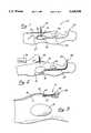
- FIG. 1is a side view of a patient illustrating a feeding tube of the present invention percutaneously accessing the stomach cavity of the patient;
- FIG. 2is a side view of the patient illustrating the insufflation of the body cavity and the inflation of the stomach cavity;
- FIG. 3is a side view of the abdominal cavity illustrating a step whereby a trocar is inserted through the abdominal wall to facilitate endoscopic visualization;
- FIG. 4is a side view similar to FIG. 3 and illustrating a step for placement of a second trocar through the abdominal wall;
- FIG. 5is a side view similar to FIG. 3 illustrating the steps of grasping, drawing and anchoring the stomach in proximity to the abdominal wall;
- FIG. 6is a side view similar to FIG. 3 illustrating further operation of the second trocar to penetrate the stomach wall;
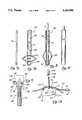
- FIG. 7ais a side elevation view of a gastrostomy tube shown in its normal high profile state and including anchor means in the form of a plurality of fingers;
- FIG. 7bis a side elevation view of a gastrostomy tube shown in its normal high profile state and including anchor means in the form of a balloon;
- FIG. 8is a side elevation view showing the distal end of the stylet engaging the distal end of the gastrostomy tube to facilitate stretching the tube along the length of the stylet;
- FIG. 9is an axial cross-section view of a locking mechanism including a first portion attached to the proximal end of the feeding tube and a second portion releasibly lockable to the first portion of the connector and attached to the proximal end of the stylet;
- FIG. 10is a side elevation view showing the feeding tube in a low profile state stretched along the length of the stylet and releasibly locked in the stretched state by the connector;
- FIG. 11is a side view similar to FIG. 3 illustrating the step for insertion of the stretched feeding tube through the cannula of the trocar;
- FIG. 12is a side view similar to FIG. 3 showing the locking mechanism unlocked and the stylet removed from the feeding tube to achieve the high profile state, with the cannula of the trocar being removed over the distal end of the feeding tube;
- FIG. 13is a side view similar to FIG. 1 and illustrating the approximation step wherein the stomach is brought into loose sealing engagement with the abdominal wall, and a funnel tip is applied to the proximal end of the feeding tube to facilitate the introduction of liquid nutrients and medicines into the stomach of the patient.
- a gastrostomy feeding tubeis illustrated in FIG. 1 and designated generally by the reference numeral 10.
- the tube 10is positioned to extend through an abdominal wall 12 into an abdominal cavity 13 of a patient 14. Within the cavity 13 the tube 10 extends toward a stomach 15, through a stomach wall 16, and into a stomach cavity 18.
- the patient 14includes an esophagus 23 which extends from a mouth 25 into fluid communication with the stomach cavity 18.
- the gastrostomy tube 10is representative of any device which provides percutaneous access to the interior regions of the patient 14. It may comprise a tube providing access with the interior regions for fluids, or it may provide access for other apparatus such as an electrical conductor or other surgical instruments.
- the stomach 15is representative of any body conduit in the digestive tract, such as the esophagus 23 or intestine 27, and or any other body conduit, cavity or organ of the patient 14, such as a bladder 30. In FIG. 1, the gastrostomy tube 10 provides direct percutaneous access into the stomach cavity 18 thereby permitting the introduction of dietary nutrients and medication directly into the digestive tract.
- Placement of the gastrostomy tube 10 or other access device into the stomach 15 or other body conduitcan be accomplished in accordance with the method and apparatus illustrated in the remaining drawings.
- an insufflation or Veress needle 34can be inserted through the abdominal wall 12 into the abdominal cavity 13. This needle 34 provides access into the abdominal cavity 13 permitting a pump 36 to introduce a pressurized gas, such as carbon dioxide directly into the cavity 13. This process, commonly referred to as insufflation, increases the volume of the cavity 13 providing an enlarged working area for laparoscopic surgery.
- the wall 16 of the stomach 15is approximately 1/8 to 1/4 inch in thickness and is highly fibrous making it relatively tough.
- the stomach wall 18is very supple. These characteristics combine to make the stomach wall 16 relatively difficult to penetrate particularly by way of a puncture. For these reasons, it may be desirable in a particular procedure to inflate the stomach cavity 18, for example by way of an esophageal tube 38 extending through the mouth 25 and the esophagus 23.
- trocar 41As in many laparoscopic procedures, visualization is provided by means of a scope placed through a trocar 41 which can be inserted through the abdominal wall 12 into the cavity 13.
- This trocar 41will typically include a cannula 43 having a seal housing 45 and an obturator 47 having a handle 50.
- the obturator 47can generally be of any type, such as the mechanical or electrosurgical varieties.
- the obturator 47can be removed leaving the cannula 43 with the associated working channel 53 providing percutaneous access into the abdominal cavity 13.
- the initial placement of this trocar 41facilitates the important visualization of all future steps in the process.
- an endoscope 61can be inserted into the working channel 53 of the cannula 43. Images present at the distal end of the endoscope 61 are transmitted by way of a cable 63 for display on a monitor 65.
- a second trocar 70including a cannula 72 having a seal housing 74 and an obturator 76 having a handle 78.
- the cannula 72 of the second trocar 70has a cylindrical configuration with an inner surface 81 defining a working channel 83 with an inside diameter, and an outer surface 87 defining an outside diameter of the cannula 72.
- the obturator 76can be of the mechanical variety, an electrosurgical obturator is of particular advantage for the reasons discussed in greater detail below.
- Such an electrosurgical obturatoris disclosed and claimed in applicant's copending application Ser. No. 08/156,958 filed on Nov. 22, 1993 and entitled Electrosurgical Trocar.
- the electrosurgical obturator 76enables the trocar 70 to be inserted with a relatively small axial force thereby facilitating placement of the cannula 72 across the abdominal wall 12.
- the obturator 76can be removed from the cannula 72, and pair of laparoscopic graspers 90 can be inserted through the working channel 83 as illustrated in FIG. 5.
- the graspers 90have a pair of serrated jaws 92 which can be opened and closed by operation of scissor handles 94. Moving the graspers 90 axially through the working channel 83 brings the jaws 92 into proximity with the stomach wall 16. Then, by operation of the handles 94, the jaws can be opened and closed to grasp the stomach wall 16. Axial retraction of the graspers 90 through the cannula 72 moves the stomach 15 into proximity with the abdominal wall 12.
- a plurality of anchorssuch as the four anchors illustrated in FIG. 6 and designated by the odd reference numbers 103-107, can be used to maintain the stomach wall 18 in this proximal location.
- Two of the anchors 101 and 103are illustrated in FIG. 5 each including a T-bar 110 and 112, respectively, and an associated suture 121 and 123, respectively.
- the anchors 101-107can be placed using an access needle 130 which is inserted percutaneously through the abdominal wall 12 and the stomach wall 16.
- the T-bar 112 with its associated suture 123can be inserted into the needle 130 and forced through the needle with a wire 132. Once the T-bar 112 clears the distal end of the needle 130 it will deploy in a generally parallel relationship to the wall 16, and the needle 130 can be removed over the suture 123.
- the graspers 90can be removed and the obturator 76 reinserted into the cannula 72 as illustrated in FIG. 6.
- stomach wall 16is relatively tough since it has a substantial thickness of 1/8 to 1/4 inch and a general fibrous consistency.
- the stomach wall 16also is very supple. These two characteristics of the stomach make it most difficult to puncture the stomach using an ordinary mechanical trocar.
- the obturator 76is energized by high frequency current from a generator 141 which is introduced to the obturator 76 through a cable 143. Energizing the electrosurgical obturator with this high frequency current tends to vaporize the cells of the stomach wall 16 effectively cutting the wall prior to its penetration by the trocar 70.
- FIG. 7aA preferred embodiment of the feeding tube 10 is illustrated in FIG. 7a.
- This tube 10has an elongate configuration which is defined by an axis 152 extending between a proximal end 154 and a distal end 156.
- the tube 10is preferably molded from latex, natural rubber, or any other material having generally elastomeric characteristics.
- the tube 10is provided with a central lumen 158 along the axis 152 which is open at the proximal end 154 but at least partially closed at the distal end 156.
- the closure at the distal endcan be implemented for example by a plug or wall 161 which at least partially blocks the lumen 158.
- This wall 161extends generally transverse, such as perpendicular, to the axis 152 and effectively closes the lumen 158.
- Supporting the wall 161 at the distal end 156 of the tube 10are a plurality of fingers 163, perhaps four in number, which are equally spaced around the circumference of the tube 10 and extend generally radially outwardly in the normal high profile state illustrated in FIG. 7a.
- These fingers 163define intervening slots 165 which are in fluid communication with the lumen 158. Accordingly, the lumen 158 and slots 165 provide a channel through which the patient 14 can be fed liquid nutrients and medications.
- the feeding tube 10includes anchor means in the form of a balloon 165.
- This balloonis inflatable through an inflation channel 166 and an inflation hole 167 beneath the balloon 165.
- the feeding tube 10 in its normal statehas a high profile along the length of the tube 10 but the balloon 165 is in a deflated state. Expansion of the balloon 165 is achieved when the balloon is inflated in order to anchor the feeding tube 10 in the stomach 15.
- the feeding tube 10 of FIG. 7balso includes the central channel 158 and a plurality of holes 168 through which the nutritive fluids can be administered.
- a stylet 170is illustrated in FIG. 7c to have a generally elongate configuration.
- the stylet 170preferably has a length greater than that of the feeding tube 10 in the normal high profile state illustrated in FIG. 7a.
- the tube 10 in the normal statehas the length of about 9.5 inches
- the stylethas a length of about 15 inches.
- the diameter of the lumen 158is about 0.2 inches
- the diameter of the styletis preferably 0.125 inches.
- the stylet 170is of particular advantage in stretching or otherwise moving the feeding tube 10 between the normal high profile state illustrated in FIGS. 7a and 7b and the stretched low profile state illustrated in FIGS. 8 and 10.
- the tube 10will have a length greater than that in the normal state, and an outside diameter which is less than that in the normal state.
- the stretching of the tube 10can be accomplished in at least two ways using the stylet 170.
- the distal end of the stylet 170is inserted through one of the slots 165 to engage the wall 161 at the distal end 156 of the tube 10.
- Drawing the proximal end 154 of the tube 10 along the stylet 170will move the tube 10 from the normal high profile state to the stretched low profile state.
- the tube 10can be held in frictional relationship against the stylet 170 to maintain the stretched low profile configuration.
- the stretched statecan be achieved and maintained with a different apparatus and method illustrated in FIGS. 9 and 10.
- This apparatusincludes a locking mechanism or connector 174 having a first connector portion 176 and a second connector portion 178.
- the first connector portion 176can be fixed to the proximal end of the feeding tube 10 while the second connector portion 178 is fixed to the proximal end of the stylet 170.
- the connector 174can be of a type manufactured by Colder Products of St. Paul, Minn., which is constructed so that the two connector portions 176 and 178 can be releasibly locked to each other.
- first connector portion 176is generally cylindrical and includes a flange 181 which extends radially outwardly.
- the outside diameter of the flange 181is preferably less than the inside diameter of the inner surface 81 of the cannula 72.
- the second connector portion 178is provided with a recess 183 which has a diameter slightly larger than the flange 181.
- a locking flange 184has a similar recess 185 and the same diameter as the recess 183.
- this locking flange 184is movable radially between an unlocked position wherein the recesses 183 and 185 are axially aligned to receive the flange 181, and an unlocked position where the recesses 183 and 185 are misaligned to 3Lock the flange 181 in the recess 183. Radial movement of the locking flange 184 is facilitated by a tab 187 which is biased by a spring 189 to the locked position.
- the stylet 170can be inserted directly into the lumen 158 to engage the wall 161 at the distal end 156 of the tube 10.
- the first connector portion 176can then be grasped and moved axially with the proximal end 154 of the tube 10, in the direction of the second connector portion 178.
- Thisstretches the tube 10 into the stretched low profile state illustrated in FIG. 10.
- the tab 187 and associated locking flange 184 of the second connector portion 178can be moved against the bias of the spring 189 inwardly to receive the flange 181 of the first connector portion 176. Releasing the tab 187 moves the locking flange 184 to the locked position retaining the flange 181 in the recess 183. In this manner, the tube 10 can be releasibly locked in its stretched low profile state.
- the tube 10 in its low profile statecan be inserted into the working channel 83 of the cannula 72.
- the tab 187 of the connector 174can be operated to release the first connector portions 176 from the second connector portions 178. This will permit the elastomeric tube 10 to automatically retract from its stretched low profile state, and move along the stylet 170 to its normal high profile state. This movement will also permit the fingers 163 to expand radially outwardly to their normal state thereby forming an anchor for the tube 10 within the stomach cavity 18 as illustrated in FIG. 12.
- the cannula 72can then be removed proximally over the tube 10 and the first connector portion 176 as illustrated in FIG. 12. Although there may be some frictional resistance to this relative movement, the fingers 163, functioning as an anchor, will tend to hold the tube in position across the abdominal wall 12 and the stomach wall 16.
- the tube 10If the tube 10 is provided with an outside diameter in its normal state which is greater than the outside diameter of the outer surface 87 of the cannula 72, then the tube 10 will automatically exert a pressure against the stomach wall 16 and the abdominal wall 12 as it attempts to become larger than the diameter of the holes left by the trocar 70. In effect, the tube 10 attempts to achieve an outside diameter which is greater than the inside diameter of the holes through which it extends. This provides excellent sealing characteristic which help to prevent leakage around the tube 10.
- One of the final steps in the processrelates to approximation between the stomach wall 16 and the abdominal wall 12. This approximation helps to develop an adhesion which will form scar tissue defining a single channel through the walls 12 and 16. Once this happens, the feeding tube 10 can be removed and replaced without further use of a trocar.
- the sutures associated with the anchors 101-107can be pulled to draw the associated T-bars and the stomach wall 16 against the abdominal wall 12.
- the sutures 121 and 123are pulled and tied together to maintain the walls 12 and 16 in juxtaposition.
- the visualization provided by the endoscope 61is of particular advantage. By viewing this procedure, the sutures 121 and 123 can be drawn sufficiently tight to bring the walls 12 and 16 into a snug sealing relationship without reducing circulation and promoting necrosis.
- first connector portion 176is provided with a reduced diameter facilitating removal of the cannula 72, it may be desirable to provide an enlarged funnel 194 for attachment to the proximal end 154 of the tube 10.
- This funnel 194will facilitate the administration of fluids to the patient 14. Attachment of the funnel 194 to the tube 10 is accomplished in the illustrated embodiment by providing an additional connector portion 196, similar to the connector portion 178, which will maintain the funnel 194 and the tube 10 in a releasibly locked relationship.
- the tube 10can be formed from many different materials although an elastomeric material is preferred in order to take advantage of the stylet 170 and the resulting choice it offers between a high profile and a low profile state. Many types of connectors can also be used for maintaining the tube 10 in the stretched low profile state. Where the connector has two portions, such as the portions 176 and 178 illustrated in FIG. 9, the smaller of these two portions is preferred for attachment to the tube 10. This facilitates removal of the cannula 72 over the smaller connector portion 176 as illustrated in FIG. 12.
Landscapes
- Health & Medical Sciences (AREA)
- Life Sciences & Earth Sciences (AREA)
- Surgery (AREA)
- Public Health (AREA)
- Animal Behavior & Ethology (AREA)
- Veterinary Medicine (AREA)
- General Health & Medical Sciences (AREA)
- Biomedical Technology (AREA)
- Nuclear Medicine, Radiotherapy & Molecular Imaging (AREA)
- Engineering & Computer Science (AREA)
- Heart & Thoracic Surgery (AREA)
- Medical Informatics (AREA)
- Molecular Biology (AREA)
- Pathology (AREA)
- Gastroenterology & Hepatology (AREA)
- Surgical Instruments (AREA)
- Media Introduction/Drainage Providing Device (AREA)
- Infusion, Injection, And Reservoir Apparatuses (AREA)
Abstract
Description
Claims (20)
Priority Applications (6)
| Application Number | Priority Date | Filing Date | Title |
|---|---|---|---|
| US08/230,165US5429598A (en) | 1994-04-19 | 1994-04-19 | Surgical access device and procedure |
| JP7527154AJPH09511934A (en) | 1994-04-19 | 1995-04-18 | Surgical access device and access method |
| PCT/US1995/004717WO1995028200A1 (en) | 1994-04-19 | 1995-04-18 | Surgical access device and procedure |
| CA002188318ACA2188318C (en) | 1994-04-19 | 1995-04-18 | Surgical access device and procedure |
| DE69527781TDE69527781T2 (en) | 1994-04-19 | 1995-04-18 | SURGICAL ACCESS DEVICE |
| EP95917021AEP0756505B1 (en) | 1994-04-19 | 1995-04-18 | Surgical access device |
Applications Claiming Priority (1)
| Application Number | Priority Date | Filing Date | Title |
|---|---|---|---|
| US08/230,165US5429598A (en) | 1994-04-19 | 1994-04-19 | Surgical access device and procedure |
Publications (1)
| Publication Number | Publication Date |
|---|---|
| US5429598Atrue US5429598A (en) | 1995-07-04 |
Family
ID=22864184
Family Applications (1)
| Application Number | Title | Priority Date | Filing Date |
|---|---|---|---|
| US08/230,165Expired - LifetimeUS5429598A (en) | 1994-04-19 | 1994-04-19 | Surgical access device and procedure |
Country Status (5)
| Country | Link |
|---|---|
| US (1) | US5429598A (en) |
| EP (1) | EP0756505B1 (en) |
| JP (1) | JPH09511934A (en) |
| DE (1) | DE69527781T2 (en) |
| WO (1) | WO1995028200A1 (en) |
Cited By (70)
| Publication number | Priority date | Publication date | Assignee | Title |
|---|---|---|---|---|
| US5626614A (en)* | 1995-12-22 | 1997-05-06 | Applied Medical Resources Corporation | T-anchor suturing device and method for using same |
| US5813976A (en)* | 1996-04-02 | 1998-09-29 | Filipi; Charles J. | Stabilizing instrumentation for the performing of endoscopic surgical procedures |
| US6077250A (en)* | 1997-10-01 | 2000-06-20 | Boston Scientific Corporation | Apparatus and method for percutaneously placing gastrostomy tubes |
| US6110183A (en)* | 1998-12-22 | 2000-08-29 | Cook Incorporated | Suture anchor device |
| WO2000064526A1 (en)* | 1999-04-23 | 2000-11-02 | Torsten Gratzki | Intervention device |
| US6423036B1 (en) | 1999-06-07 | 2002-07-23 | Gibbons Surgical Corporation | Cannula anchoring port |
| WO2002085225A1 (en)* | 2001-04-19 | 2002-10-31 | Scimed Life Systems, Inc. | Apparatus and method for the insertion of a medical device |
| US20030158572A1 (en)* | 2002-02-15 | 2003-08-21 | Mcfarlane Richard H. | Anchoring assembly for a medical instrument |
| WO2004069035A3 (en)* | 2003-01-31 | 2005-04-14 | Flex Partners Inc | System and method for rapid placement of chest tubes |
| US20050209619A1 (en)* | 2004-03-22 | 2005-09-22 | Johnson Gary M | Surgical access port and method of using same |
| US20050251207A1 (en)* | 2004-05-07 | 2005-11-10 | Usgi Medical Inc. | Apparatus and methods for positioning and securing anchors |
| US20050261661A1 (en)* | 2002-04-26 | 2005-11-24 | Mcfarlane Richard H | Floating seal assembly for a trocar |
| US20050273116A1 (en)* | 2003-01-31 | 2005-12-08 | Simpson Philip J | System and method for rapid placement of chest tubes |
| US7189235B2 (en) | 1999-10-20 | 2007-03-13 | Anulex Technologies, Inc. | Spinal disc annulus reconstruction method and spinal disc annulus stent |
| WO2007035526A2 (en) | 2005-09-16 | 2007-03-29 | Applied Medical Technology, Inc. | Non-balloon low profile feed device with insertion/removal tool |
| US20070167966A1 (en)* | 2003-01-31 | 2007-07-19 | Simpson Philip J | Manipulation and cutting system and method |
| US20070276356A1 (en)* | 2004-06-29 | 2007-11-29 | C. R. Bard, Inc. | Methods And Systems For Providing Fluid Communication With A Gastrostomy Tube |
| US20080015501A1 (en)* | 2004-03-23 | 2008-01-17 | Michael Gertner | Abdominal Wall Balloon To Treat Obesity |
| US20080051739A1 (en)* | 2006-08-25 | 2008-02-28 | Mcfarlane Richard H | Caged floating seal assembly |
| US7347863B2 (en) | 2004-05-07 | 2008-03-25 | Usgi Medical, Inc. | Apparatus and methods for manipulating and securing tissue |
| US7361180B2 (en) | 2004-05-07 | 2008-04-22 | Usgi Medical, Inc. | Apparatus for manipulating and securing tissue |
| US20080125796A1 (en)* | 2006-11-28 | 2008-05-29 | Stryker Development Llc | Gastrotomy closure device |
| US7390329B2 (en) | 2004-05-07 | 2008-06-24 | Usgi Medical, Inc. | Methods for grasping and cinching tissue anchors |
| US7416554B2 (en) | 2002-12-11 | 2008-08-26 | Usgi Medical Inc | Apparatus and methods for forming and securing gastrointestinal tissue folds |
| US20080275297A1 (en)* | 2007-05-01 | 2008-11-06 | Ethicon Endo-Surgery, Inc. | Endoscopic guide device |
| US7571729B2 (en) | 2004-03-09 | 2009-08-11 | Usgi Medical, Inc. | Apparatus and methods for performing mucosectomy |
| US7601159B2 (en) | 2004-05-07 | 2009-10-13 | Usgi Medical, Inc. | Interlocking tissue anchor apparatus and methods |
| US7615076B2 (en) | 1999-10-20 | 2009-11-10 | Anulex Technologies, Inc. | Method and apparatus for the treatment of the intervertebral disc annulus |
| US7618426B2 (en) | 2002-12-11 | 2009-11-17 | Usgi Medical, Inc. | Apparatus and methods for forming gastrointestinal tissue approximations |
| US20100016884A1 (en)* | 2006-03-13 | 2010-01-21 | Mini-Lap Techonologies, Inc. | Minimally Invasive Surgical Assembly and Methods |
| US7678135B2 (en) | 2004-06-09 | 2010-03-16 | Usgi Medical, Inc. | Compressible tissue anchor assemblies |
| US7695493B2 (en) | 2004-06-09 | 2010-04-13 | Usgi Medical, Inc. | System for optimizing anchoring force |
| US7704264B2 (en) | 1999-06-25 | 2010-04-27 | Usgi Medical, Inc. | Apparatus and methods for forming and securing gastrointestinal tissue folds |
| US7736379B2 (en) | 2004-06-09 | 2010-06-15 | Usgi Medical, Inc. | Compressible tissue anchor assemblies |
| US7736374B2 (en) | 2004-05-07 | 2010-06-15 | Usgi Medical, Inc. | Tissue manipulation and securement system |
| US7753941B2 (en) | 2000-04-04 | 2010-07-13 | Anulex Technologies, Inc. | Devices and methods for annular repair of intervertebral discs |
| US7828850B2 (en) | 1999-10-20 | 2010-11-09 | Anulex Technologies, Inc. | Methods and devices for spinal disc annulus reconstruction and repair |
| US20110034775A1 (en)* | 2009-02-25 | 2011-02-10 | Lozman Philip R | Surgical Retention Port and Method of Use |
| US7918869B2 (en) | 2004-05-07 | 2011-04-05 | Usgi Medical, Inc. | Methods and apparatus for performing endoluminal gastroplasty |
| US7918845B2 (en) | 2003-01-15 | 2011-04-05 | Usgi Medical, Inc. | Endoluminal tool deployment system |
| US7922768B2 (en) | 1999-10-20 | 2011-04-12 | Anulex Technologies, Inc. | Spinal disc annulus reconstruction method and deformable spinal disc annulus stent |
| US7935147B2 (en) | 1999-10-20 | 2011-05-03 | Anulex Technologies, Inc. | Method and apparatus for enhanced delivery of treatment device to the intervertebral disc annulus |
| US20110106113A1 (en)* | 2007-07-13 | 2011-05-05 | The Brigham And Women's Hospital, Inc. | System and method for hernia mesh fixation |
| US7942898B2 (en) | 2002-12-11 | 2011-05-17 | Usgi Medical, Inc. | Delivery systems and methods for gastric reduction |
| US7942884B2 (en) | 2002-12-11 | 2011-05-17 | Usgi Medical, Inc. | Methods for reduction of a gastric lumen |
| US7951201B2 (en) | 1999-10-20 | 2011-05-31 | Anulex Technologies, Inc. | Method and apparatus for the treatment of the intervertebral disc annulus |
| US20110288488A1 (en)* | 2006-10-26 | 2011-11-24 | Cook Medical Technologies Llc | Inside out t-fastener system |
| US8128698B2 (en) | 1999-10-20 | 2012-03-06 | Anulex Technologies, Inc. | Method and apparatus for the treatment of the intervertebral disc annulus |
| US8163022B2 (en) | 2008-10-14 | 2012-04-24 | Anulex Technologies, Inc. | Method and apparatus for the treatment of the intervertebral disc annulus |
| US8206417B2 (en) | 2004-06-09 | 2012-06-26 | Usgi Medical Inc. | Apparatus and methods for optimizing anchoring force |
| US8216252B2 (en) | 2004-05-07 | 2012-07-10 | Usgi Medical, Inc. | Tissue manipulation and securement system |
| US8257394B2 (en) | 2004-05-07 | 2012-09-04 | Usgi Medical, Inc. | Apparatus and methods for positioning and securing anchors |
| US20120238959A1 (en)* | 2011-03-14 | 2012-09-20 | C.R. Bard, Inc. | Biased Internal Bolster for a Medical Device |
| US8298291B2 (en) | 2005-05-26 | 2012-10-30 | Usgi Medical, Inc. | Methods and apparatus for securing and deploying tissue anchors |
| WO2012160134A1 (en)* | 2011-05-24 | 2012-11-29 | Fresenius Kabi Deutschland Gmbh | Probe for the enteral nutrition of a patient |
| EP2158859B1 (en)* | 2005-10-13 | 2013-04-17 | Covidien LP | Trocar anchor |
| US8444657B2 (en) | 2004-05-07 | 2013-05-21 | Usgi Medical, Inc. | Apparatus and methods for rapid deployment of tissue anchors |
| US8460319B2 (en) | 2010-01-11 | 2013-06-11 | Anulex Technologies, Inc. | Intervertebral disc annulus repair system and method |
| US8556977B2 (en) | 1999-10-20 | 2013-10-15 | Anulex Technologies, Inc. | Tissue anchoring system and method |
| US8726909B2 (en) | 2006-01-27 | 2014-05-20 | Usgi Medical, Inc. | Methods and apparatus for revision of obesity procedures |
| US8821392B2 (en) | 2009-02-25 | 2014-09-02 | Joint Product Solutions, Llc | Surgical retention port and method of use |
| US8870916B2 (en) | 2006-07-07 | 2014-10-28 | USGI Medical, Inc | Low profile tissue anchors, tissue anchor systems, and methods for their delivery and use |
| US9211234B2 (en) | 2010-09-27 | 2015-12-15 | Avent, Inc. | Configurable percutaneous endoscopic gastrostomy tube |
| US9265514B2 (en) | 2012-04-17 | 2016-02-23 | Miteas Ltd. | Manipulator for grasping tissue |
| US9271752B2 (en) | 2013-03-13 | 2016-03-01 | Swan Valley Medical Incorporated | Method and apparatus for placing a cannula in a bladder |
| US9326757B2 (en) | 2009-12-31 | 2016-05-03 | Teleflex Medical Incorporated | Surgical instruments for laparoscopic aspiration and retraction |
| US9572751B2 (en) | 2009-07-07 | 2017-02-21 | C. R. Bard, Inc. | Extensible internal bolster for a medical device |
| US9585651B2 (en) | 2005-05-26 | 2017-03-07 | Usgi Medical, Inc. | Methods and apparatus for securing and deploying tissue anchors |
| US9737294B2 (en) | 2013-01-28 | 2017-08-22 | Cartiva, Inc. | Method and system for orthopedic repair |
| US10179012B2 (en) | 2013-01-28 | 2019-01-15 | Cartiva, Inc. | Systems and methods for orthopedic repair |
Families Citing this family (1)
| Publication number | Priority date | Publication date | Assignee | Title |
|---|---|---|---|---|
| US20090131967A1 (en) | 2007-11-16 | 2009-05-21 | Hollis Jeffrey D | Surgical trocar |
Citations (7)
| Publication number | Priority date | Publication date | Assignee | Title |
|---|---|---|---|---|
| US5071405A (en)* | 1989-06-02 | 1991-12-10 | Abbott Laboratories | Gastrostomy tube |
| USRE34021E (en)* | 1985-11-18 | 1992-08-04 | Abbott Laboratories | Percutaneous fixation of hollow organs |
| US5151086A (en)* | 1991-10-22 | 1992-09-29 | The Regents Of The University Of California | Laparoscopic tube placement method |
| US5167627A (en)* | 1990-09-13 | 1992-12-01 | Abbott Laboratories | Stoma creator gastrostomy device and method for placement of a feeding tube |
| US5250025A (en)* | 1990-08-15 | 1993-10-05 | Intramed Laboratories | Percutaneous access catheter and method of use |
| US5279553A (en)* | 1992-04-02 | 1994-01-18 | Martin J. Winkler | Transpyloric jejunostomy cannulating system |
| US5281204A (en)* | 1989-12-26 | 1994-01-25 | Nissho Corporation | Device for forming an inserting hole and method of using and making the same |
Family Cites Families (5)
| Publication number | Priority date | Publication date | Assignee | Title |
|---|---|---|---|---|
| DE3814618C1 (en)* | 1988-04-29 | 1989-02-02 | Rainer Dr. 8000 Muenchen De Baumgart | |
| US4861334A (en)* | 1988-06-24 | 1989-08-29 | Nawaz Arain | Self-retaining gastrostomy tube |
| US5234425A (en)* | 1989-03-03 | 1993-08-10 | Thomas J. Fogarty | Variable diameter sheath method and apparatus for use in body passages |
| US5158545A (en)* | 1991-05-02 | 1992-10-27 | Brigham And Women's Hospital | Diameter expansion cannula |
| US5431676A (en)* | 1993-03-05 | 1995-07-11 | Innerdyne Medical, Inc. | Trocar system having expandable port |
- 1994
- 1994-04-19USUS08/230,165patent/US5429598A/ennot_activeExpired - Lifetime
- 1995
- 1995-04-18DEDE69527781Tpatent/DE69527781T2/ennot_activeExpired - Lifetime
- 1995-04-18EPEP95917021Apatent/EP0756505B1/ennot_activeExpired - Lifetime
- 1995-04-18JPJP7527154Apatent/JPH09511934A/enactivePending
- 1995-04-18WOPCT/US1995/004717patent/WO1995028200A1/enactiveIP Right Grant
Patent Citations (7)
| Publication number | Priority date | Publication date | Assignee | Title |
|---|---|---|---|---|
| USRE34021E (en)* | 1985-11-18 | 1992-08-04 | Abbott Laboratories | Percutaneous fixation of hollow organs |
| US5071405A (en)* | 1989-06-02 | 1991-12-10 | Abbott Laboratories | Gastrostomy tube |
| US5281204A (en)* | 1989-12-26 | 1994-01-25 | Nissho Corporation | Device for forming an inserting hole and method of using and making the same |
| US5250025A (en)* | 1990-08-15 | 1993-10-05 | Intramed Laboratories | Percutaneous access catheter and method of use |
| US5167627A (en)* | 1990-09-13 | 1992-12-01 | Abbott Laboratories | Stoma creator gastrostomy device and method for placement of a feeding tube |
| US5151086A (en)* | 1991-10-22 | 1992-09-29 | The Regents Of The University Of California | Laparoscopic tube placement method |
| US5279553A (en)* | 1992-04-02 | 1994-01-18 | Martin J. Winkler | Transpyloric jejunostomy cannulating system |
Non-Patent Citations (4)
| Title |
|---|
| "18 French Flexiflo Lap G", Ross Product Division, Abbott Laboratories, 1993, (product brochure). |
| "Laparoscopic Placement of Gastrostomy Feeding Tube", Ross Product Division, Abbott Laboratories, Mar. 1993. (product brochure). |
| 18 French Flexiflo Lap G , Ross Product Division, Abbott Laboratories, 1993, (product brochure).* |
| Laparoscopic Placement of Gastrostomy Feeding Tube , Ross Product Division, Abbott Laboratories, Mar. 1993. (product brochure).* |
Cited By (147)
| Publication number | Priority date | Publication date | Assignee | Title |
|---|---|---|---|---|
| US5626614A (en)* | 1995-12-22 | 1997-05-06 | Applied Medical Resources Corporation | T-anchor suturing device and method for using same |
| US5813976A (en)* | 1996-04-02 | 1998-09-29 | Filipi; Charles J. | Stabilizing instrumentation for the performing of endoscopic surgical procedures |
| US6077250A (en)* | 1997-10-01 | 2000-06-20 | Boston Scientific Corporation | Apparatus and method for percutaneously placing gastrostomy tubes |
| US6402722B1 (en) | 1997-10-01 | 2002-06-11 | Scimed Life Systems, Inc. | Apparatus and method for percutaneously placing gastrostomy tubes |
| US6110183A (en)* | 1998-12-22 | 2000-08-29 | Cook Incorporated | Suture anchor device |
| WO2000064526A1 (en)* | 1999-04-23 | 2000-11-02 | Torsten Gratzki | Intervention device |
| US6423036B1 (en) | 1999-06-07 | 2002-07-23 | Gibbons Surgical Corporation | Cannula anchoring port |
| US8574243B2 (en) | 1999-06-25 | 2013-11-05 | Usgi Medical, Inc. | Apparatus and methods for forming and securing gastrointestinal tissue folds |
| US7704264B2 (en) | 1999-06-25 | 2010-04-27 | Usgi Medical, Inc. | Apparatus and methods for forming and securing gastrointestinal tissue folds |
| US7744613B2 (en) | 1999-06-25 | 2010-06-29 | Usgi Medical, Inc. | Apparatus and methods for forming and securing gastrointestinal tissue folds |
| US7955340B2 (en) | 1999-06-25 | 2011-06-07 | Usgi Medical, Inc. | Apparatus and methods for forming and securing gastrointestinal tissue folds |
| US8343175B2 (en) | 1999-06-25 | 2013-01-01 | Usgi Medical, Inc. | Apparatus and methods for forming and securing gastrointestinal tissue folds |
| US7951201B2 (en) | 1999-10-20 | 2011-05-31 | Anulex Technologies, Inc. | Method and apparatus for the treatment of the intervertebral disc annulus |
| US7985257B2 (en) | 1999-10-20 | 2011-07-26 | Anulex Technologies, Inc. | Methods and devices for spinal disc annulus reconstruction and repair |
| US9095442B2 (en) | 1999-10-20 | 2015-08-04 | Krt Investors, Inc. | Method and apparatus for the treatment of the intervertebral disc annulus |
| US7749273B2 (en) | 1999-10-20 | 2010-07-06 | Anulex Technologies, Inc. | Method and apparatus for the treatment of the intervertebral disc annulus |
| US8632590B2 (en) | 1999-10-20 | 2014-01-21 | Anulex Technologies, Inc. | Apparatus and methods for the treatment of the intervertebral disc |
| US7828850B2 (en) | 1999-10-20 | 2010-11-09 | Anulex Technologies, Inc. | Methods and devices for spinal disc annulus reconstruction and repair |
| US7670379B2 (en) | 1999-10-20 | 2010-03-02 | Anulex Technologies, Inc. | Spinal disc annulus reconstruction method |
| US7189235B2 (en) | 1999-10-20 | 2007-03-13 | Anulex Technologies, Inc. | Spinal disc annulus reconstruction method and spinal disc annulus stent |
| US7909879B2 (en) | 1999-10-20 | 2011-03-22 | Anulex Technologies, Inc. | Intervertebral disc annulus stent |
| US8556977B2 (en) | 1999-10-20 | 2013-10-15 | Anulex Technologies, Inc. | Tissue anchoring system and method |
| US7615076B2 (en) | 1999-10-20 | 2009-11-10 | Anulex Technologies, Inc. | Method and apparatus for the treatment of the intervertebral disc annulus |
| US9675347B2 (en) | 1999-10-20 | 2017-06-13 | Krt Investors, Inc. | Apparatus for the treatment of tissue |
| US8128698B2 (en) | 1999-10-20 | 2012-03-06 | Anulex Technologies, Inc. | Method and apparatus for the treatment of the intervertebral disc annulus |
| US8088165B2 (en) | 1999-10-20 | 2012-01-03 | Anulex Technologies, Inc. | Spinal disc annulus reconstruction method and deformable spinal disc annulus stent |
| US8048160B2 (en) | 1999-10-20 | 2011-11-01 | Anulex Technologies, Inc. | Intervertebral disc annulus stent |
| US8034112B2 (en) | 1999-10-20 | 2011-10-11 | Anulex Technologies, Inc. | Spinal disc annulus reconstruction method and spinal disc annulus stent |
| US7993405B2 (en) | 1999-10-20 | 2011-08-09 | Anulex Technologies, Inc. | Spinal disc annulus repair system and methods |
| US9114025B2 (en) | 1999-10-20 | 2015-08-25 | Krt Investors, Inc. | Methods and devices for spinal disc annulus reconstruction and repair |
| US7963992B2 (en) | 1999-10-20 | 2011-06-21 | Anulex Technologies, Inc. | Method and apparatus for the treatment of the intervertebral disc annulus |
| US7922768B2 (en) | 1999-10-20 | 2011-04-12 | Anulex Technologies, Inc. | Spinal disc annulus reconstruction method and deformable spinal disc annulus stent |
| US7935147B2 (en) | 1999-10-20 | 2011-05-03 | Anulex Technologies, Inc. | Method and apparatus for enhanced delivery of treatment device to the intervertebral disc annulus |
| US7905923B2 (en) | 2000-04-04 | 2011-03-15 | Anulex Technologies, Inc. | Devices and methods for annular repair of intervertebral discs |
| US7753941B2 (en) | 2000-04-04 | 2010-07-13 | Anulex Technologies, Inc. | Devices and methods for annular repair of intervertebral discs |
| US6743207B2 (en) | 2001-04-19 | 2004-06-01 | Scimed Life Systems, Inc. | Apparatus and method for the insertion of a medical device |
| US20040193114A1 (en)* | 2001-04-19 | 2004-09-30 | Elbert Linda D. | Apparatus and method for the insertion of a medical device |
| US7959610B2 (en) | 2001-04-19 | 2011-06-14 | Boston Scientific Scimed, Inc. | Apparatus and method for the insertion of a medical device |
| US20070142778A1 (en)* | 2001-04-19 | 2007-06-21 | Elbert Linda D | Apparatus and method for the insertion of a medical device |
| US7186238B2 (en) | 2001-04-19 | 2007-03-06 | Boston Scientific Scimed, Inc. | Apparatus and method for the insertion of a medical device |
| WO2002085225A1 (en)* | 2001-04-19 | 2002-10-31 | Scimed Life Systems, Inc. | Apparatus and method for the insertion of a medical device |
| US20030158572A1 (en)* | 2002-02-15 | 2003-08-21 | Mcfarlane Richard H. | Anchoring assembly for a medical instrument |
| US6908454B2 (en) | 2002-02-15 | 2005-06-21 | Taut, Inc. | Anchoring assembly for a medical instrument |
| US7011314B2 (en) | 2002-04-26 | 2006-03-14 | Taut, Inc. | Floating seal assembly for a trocar |
| US20050261661A1 (en)* | 2002-04-26 | 2005-11-24 | Mcfarlane Richard H | Floating seal assembly for a trocar |
| US7618426B2 (en) | 2002-12-11 | 2009-11-17 | Usgi Medical, Inc. | Apparatus and methods for forming gastrointestinal tissue approximations |
| US7416554B2 (en) | 2002-12-11 | 2008-08-26 | Usgi Medical Inc | Apparatus and methods for forming and securing gastrointestinal tissue folds |
| US7942884B2 (en) | 2002-12-11 | 2011-05-17 | Usgi Medical, Inc. | Methods for reduction of a gastric lumen |
| US7942898B2 (en) | 2002-12-11 | 2011-05-17 | Usgi Medical, Inc. | Delivery systems and methods for gastric reduction |
| US8066719B2 (en) | 2002-12-11 | 2011-11-29 | Ewers Richard C | Apparatus and methods for forming gastrointestinal tissue approximations |
| US8216260B2 (en) | 2002-12-11 | 2012-07-10 | Usgi Medical, Inc. | Apparatus and methods for forming and securing gastrointestinal tissue folds |
| US8262676B2 (en) | 2002-12-11 | 2012-09-11 | Usgi Medical, Inc. | Apparatus and methods for forming gastrointestinal tissue approximations |
| US7918845B2 (en) | 2003-01-15 | 2011-04-05 | Usgi Medical, Inc. | Endoluminal tool deployment system |
| US7842058B2 (en) | 2003-01-31 | 2010-11-30 | Flex Partners, Inc. | Manipulation and cutting system and method |
| WO2004069035A3 (en)* | 2003-01-31 | 2005-04-14 | Flex Partners Inc | System and method for rapid placement of chest tubes |
| AU2010201427B8 (en)* | 2003-01-31 | 2010-06-10 | Walter Dean Gillespie | System and method for rapid placement of chest tubes |
| US7811293B2 (en) | 2003-01-31 | 2010-10-12 | Philip J. Simpson | System and method for rapid placement of chest tubes |
| US20050273116A1 (en)* | 2003-01-31 | 2005-12-08 | Simpson Philip J | System and method for rapid placement of chest tubes |
| US20070167966A1 (en)* | 2003-01-31 | 2007-07-19 | Simpson Philip J | Manipulation and cutting system and method |
| AU2010201427B2 (en)* | 2003-01-31 | 2010-06-03 | Walter Dean Gillespie | System and method for rapid placement of chest tubes |
| AU2004209999B2 (en)* | 2003-01-31 | 2010-04-29 | Walter Dean Gillespie | System and method for rapid placement of chest tubes |
| US10045871B2 (en) | 2003-12-12 | 2018-08-14 | Usgi Medical, Inc. | Apparatus for manipulating and securing tissue |
| US9510817B2 (en) | 2003-12-12 | 2016-12-06 | Usgi Medical, Inc. | Apparatus for manipulating and securing tissue |
| US7703459B2 (en) | 2004-03-09 | 2010-04-27 | Usgi Medical, Inc. | Apparatus and methods for mapping out endoluminal gastrointestinal surgery |
| US7571729B2 (en) | 2004-03-09 | 2009-08-11 | Usgi Medical, Inc. | Apparatus and methods for performing mucosectomy |
| US20050209619A1 (en)* | 2004-03-22 | 2005-09-22 | Johnson Gary M | Surgical access port and method of using same |
| US8007477B2 (en) | 2004-03-22 | 2011-08-30 | Applied Medical Resources Corporation | Surgical access port and method of using same |
| US8715251B2 (en) | 2004-03-22 | 2014-05-06 | Applied Medical Resources Corporation | Surgical access port and method of using same |
| US10124156B2 (en) | 2004-03-22 | 2018-11-13 | Applied Medical Resources Corporation | Surgical access port and method of using same |
| US20080015501A1 (en)* | 2004-03-23 | 2008-01-17 | Michael Gertner | Abdominal Wall Balloon To Treat Obesity |
| US8308765B2 (en) | 2004-05-07 | 2012-11-13 | Usgi Medical, Inc. | Apparatus and methods for positioning and securing anchors |
| US8236009B2 (en) | 2004-05-07 | 2012-08-07 | Usgi Medical, Inc. | Needle assembly for tissue manipulation |
| US7390329B2 (en) | 2004-05-07 | 2008-06-24 | Usgi Medical, Inc. | Methods for grasping and cinching tissue anchors |
| US11045341B2 (en) | 2004-05-07 | 2021-06-29 | Usgi Medical, Inc. | Apparatus for manipulating and securing tissue |
| US7736378B2 (en) | 2004-05-07 | 2010-06-15 | Usgi Medical, Inc. | Apparatus and methods for positioning and securing anchors |
| US7361180B2 (en) | 2004-05-07 | 2008-04-22 | Usgi Medical, Inc. | Apparatus for manipulating and securing tissue |
| US8828027B2 (en) | 2004-05-07 | 2014-09-09 | U.S.G.I. Medical, Inc. | Tissue manipulation and securement system |
| US7347863B2 (en) | 2004-05-07 | 2008-03-25 | Usgi Medical, Inc. | Apparatus and methods for manipulating and securing tissue |
| US8444657B2 (en) | 2004-05-07 | 2013-05-21 | Usgi Medical, Inc. | Apparatus and methods for rapid deployment of tissue anchors |
| US8057511B2 (en) | 2004-05-07 | 2011-11-15 | Usgi Medical, Inc. | Apparatus and methods for positioning and securing anchors |
| US8926634B2 (en) | 2004-05-07 | 2015-01-06 | Usgi Medical, Inc. | Apparatus and methods for manipulating and securing tissue |
| US7601159B2 (en) | 2004-05-07 | 2009-10-13 | Usgi Medical, Inc. | Interlocking tissue anchor apparatus and methods |
| US20050251207A1 (en)* | 2004-05-07 | 2005-11-10 | Usgi Medical Inc. | Apparatus and methods for positioning and securing anchors |
| US7621925B2 (en) | 2004-05-07 | 2009-11-24 | Usgi Medical, Inc. | Needle assembly for tissue manipulation |
| US7736374B2 (en) | 2004-05-07 | 2010-06-15 | Usgi Medical, Inc. | Tissue manipulation and securement system |
| US8257394B2 (en) | 2004-05-07 | 2012-09-04 | Usgi Medical, Inc. | Apparatus and methods for positioning and securing anchors |
| US8216253B2 (en) | 2004-05-07 | 2012-07-10 | Usgi Medical, Inc. | Apparatus for manipulating and securing tissue |
| US7918869B2 (en) | 2004-05-07 | 2011-04-05 | Usgi Medical, Inc. | Methods and apparatus for performing endoluminal gastroplasty |
| US8216252B2 (en) | 2004-05-07 | 2012-07-10 | Usgi Medical, Inc. | Tissue manipulation and securement system |
| US8382800B2 (en) | 2004-06-09 | 2013-02-26 | Usgi Medical, Inc. | Compressible tissue anchor assemblies |
| US7736379B2 (en) | 2004-06-09 | 2010-06-15 | Usgi Medical, Inc. | Compressible tissue anchor assemblies |
| US8740940B2 (en) | 2004-06-09 | 2014-06-03 | Usgi Medical, Inc. | Compressible tissue anchor assemblies |
| US7695493B2 (en) | 2004-06-09 | 2010-04-13 | Usgi Medical, Inc. | System for optimizing anchoring force |
| US8206417B2 (en) | 2004-06-09 | 2012-06-26 | Usgi Medical Inc. | Apparatus and methods for optimizing anchoring force |
| US7678135B2 (en) | 2004-06-09 | 2010-03-16 | Usgi Medical, Inc. | Compressible tissue anchor assemblies |
| US20070276356A1 (en)* | 2004-06-29 | 2007-11-29 | C. R. Bard, Inc. | Methods And Systems For Providing Fluid Communication With A Gastrostomy Tube |
| US9682224B2 (en) | 2004-06-29 | 2017-06-20 | C. R. Bard, Inc. | Method and systems for providing fluid communication with a gastrostomy tube |
| US8858533B2 (en) | 2004-06-29 | 2014-10-14 | C. R. Bard, Inc. | Methods and systems for providing fluid communication with a gastrostomy tube |
| US8298291B2 (en) | 2005-05-26 | 2012-10-30 | Usgi Medical, Inc. | Methods and apparatus for securing and deploying tissue anchors |
| US9585651B2 (en) | 2005-05-26 | 2017-03-07 | Usgi Medical, Inc. | Methods and apparatus for securing and deploying tissue anchors |
| US8709018B2 (en) | 2005-09-16 | 2014-04-29 | Applied Medical Technology, Inc. | Non-balloon low profile feed device with insertion/removal tool |
| EP1933790A4 (en)* | 2005-09-16 | 2009-11-04 | Applied Med Tech Inc | Non-balloon low profile feed device with insertion/removal tool |
| US20070078465A1 (en)* | 2005-09-16 | 2007-04-05 | Applied Medical Technology, Inc. | Non-balloon low profile feed device with insertion/removal tool |
| WO2007035526A2 (en) | 2005-09-16 | 2007-03-29 | Applied Medical Technology, Inc. | Non-balloon low profile feed device with insertion/removal tool |
| EP2158859B1 (en)* | 2005-10-13 | 2013-04-17 | Covidien LP | Trocar anchor |
| US8726909B2 (en) | 2006-01-27 | 2014-05-20 | Usgi Medical, Inc. | Methods and apparatus for revision of obesity procedures |
| US20100016884A1 (en)* | 2006-03-13 | 2010-01-21 | Mini-Lap Techonologies, Inc. | Minimally Invasive Surgical Assembly and Methods |
| US9326784B2 (en) | 2006-03-13 | 2016-05-03 | Teleflex Medical Incorporated | Minimally invasive surgical assembly and methods |
| US8870916B2 (en) | 2006-07-07 | 2014-10-28 | USGI Medical, Inc | Low profile tissue anchors, tissue anchor systems, and methods for their delivery and use |
| US20100241080A1 (en)* | 2006-08-25 | 2010-09-23 | Teleflex Medical Incorporated | Caged floating seal assembly |
| US9901373B2 (en) | 2006-08-25 | 2018-02-27 | Teleflex Medical Incorporated | Caged floating seal assembly |
| US20080051739A1 (en)* | 2006-08-25 | 2008-02-28 | Mcfarlane Richard H | Caged floating seal assembly |
| US10799267B2 (en) | 2006-08-25 | 2020-10-13 | Teleflex Medical Incorporated | Caged floating seal assembly |
| US7731695B2 (en) | 2006-08-25 | 2010-06-08 | Teleflex Medical Incorporated | Caged floating seal assembly |
| US8821445B2 (en) | 2006-08-25 | 2014-09-02 | Teleflex Medical Incorporated | Caged floating seal assembly |
| US8287558B2 (en)* | 2006-10-26 | 2012-10-16 | Cook Medical Technologies Llc | Inside out T-fastener system |
| US20110288488A1 (en)* | 2006-10-26 | 2011-11-24 | Cook Medical Technologies Llc | Inside out t-fastener system |
| US20080125796A1 (en)* | 2006-11-28 | 2008-05-29 | Stryker Development Llc | Gastrotomy closure device |
| US20080275297A1 (en)* | 2007-05-01 | 2008-11-06 | Ethicon Endo-Surgery, Inc. | Endoscopic guide device |
| US7967741B2 (en) | 2007-05-01 | 2011-06-28 | Ethicon Endo-Surgery, Inc. | Endoscopic guide device |
| US20110106113A1 (en)* | 2007-07-13 | 2011-05-05 | The Brigham And Women's Hospital, Inc. | System and method for hernia mesh fixation |
| US8163022B2 (en) | 2008-10-14 | 2012-04-24 | Anulex Technologies, Inc. | Method and apparatus for the treatment of the intervertebral disc annulus |
| US8454697B2 (en) | 2008-10-14 | 2013-06-04 | Anulex Technologies, Inc. | Method and apparatus for the treatment of tissue |
| US9192372B2 (en) | 2008-10-14 | 2015-11-24 | Krt Investors, Inc. | Method for the treatment of tissue |
| US20110034775A1 (en)* | 2009-02-25 | 2011-02-10 | Lozman Philip R | Surgical Retention Port and Method of Use |
| US8771179B2 (en) | 2009-02-25 | 2014-07-08 | Joint Product Solutions, Llc | Surgical retention port and method of use |
| US8821392B2 (en) | 2009-02-25 | 2014-09-02 | Joint Product Solutions, Llc | Surgical retention port and method of use |
| US8409085B2 (en) | 2009-02-25 | 2013-04-02 | Joint Product Solutions, Llc | Surgical retention port and method of use |
| US9572751B2 (en) | 2009-07-07 | 2017-02-21 | C. R. Bard, Inc. | Extensible internal bolster for a medical device |
| US9326757B2 (en) | 2009-12-31 | 2016-05-03 | Teleflex Medical Incorporated | Surgical instruments for laparoscopic aspiration and retraction |
| US9795372B2 (en) | 2010-01-11 | 2017-10-24 | Krt Investors, Inc. | Intervertebral disc annulus repair system and bone anchor delivery tool |
| US8460319B2 (en) | 2010-01-11 | 2013-06-11 | Anulex Technologies, Inc. | Intervertebral disc annulus repair system and method |
| US8652153B2 (en) | 2010-01-11 | 2014-02-18 | Anulex Technologies, Inc. | Intervertebral disc annulus repair system and bone anchor delivery tool |
| US9211234B2 (en) | 2010-09-27 | 2015-12-15 | Avent, Inc. | Configurable percutaneous endoscopic gastrostomy tube |
| US20120238959A1 (en)* | 2011-03-14 | 2012-09-20 | C.R. Bard, Inc. | Biased Internal Bolster for a Medical Device |
| WO2012160134A1 (en)* | 2011-05-24 | 2012-11-29 | Fresenius Kabi Deutschland Gmbh | Probe for the enteral nutrition of a patient |
| CN103547246B (en)* | 2011-05-24 | 2016-06-15 | 费森尤斯卡比德国有限公司 | For the conduit of patients with enteral nutrition caused |
| CN103547246A (en)* | 2011-05-24 | 2014-01-29 | 弗雷泽纽斯卡比德国有限公司 | Probe for the enteral nutrition of a patient |
| US12207831B2 (en) | 2012-04-17 | 2025-01-28 | A-Base Korlatolt Felelossegu Tarsasag | Manipulator for grasping tissue |
| US9610088B2 (en) | 2012-04-17 | 2017-04-04 | A-Base Korlatolt Felelossegu Tarsasag | Manipulator for grasping tissue |
| US9265514B2 (en) | 2012-04-17 | 2016-02-23 | Miteas Ltd. | Manipulator for grasping tissue |
| US11633203B2 (en) | 2012-04-17 | 2023-04-25 | A-Base Korlatolt Felelossegu Tarsasag | Manipulator for grasping tissue |
| US10441302B2 (en) | 2012-04-17 | 2019-10-15 | A-Base Korlatolt Felelossegu Tarsasag | Manipulator for grasping tissue |
| US9737294B2 (en) | 2013-01-28 | 2017-08-22 | Cartiva, Inc. | Method and system for orthopedic repair |
| US11471199B2 (en) | 2013-01-28 | 2022-10-18 | Cartiva, Inc. | Systems and methods for orthopedic repair |
| US10179012B2 (en) | 2013-01-28 | 2019-01-15 | Cartiva, Inc. | Systems and methods for orthopedic repair |
| US9271752B2 (en) | 2013-03-13 | 2016-03-01 | Swan Valley Medical Incorporated | Method and apparatus for placing a cannula in a bladder |
Also Published As
| Publication number | Publication date |
|---|---|
| JPH09511934A (en) | 1997-12-02 |
| DE69527781D1 (en) | 2002-09-19 |
| EP0756505A1 (en) | 1997-02-05 |
| WO1995028200A1 (en) | 1995-10-26 |
| EP0756505A4 (en) | 1999-02-24 |
| DE69527781T2 (en) | 2002-12-05 |
| EP0756505B1 (en) | 2002-08-14 |
Similar Documents
| Publication | Publication Date | Title |
|---|---|---|
| US5429598A (en) | Surgical access device and procedure | |
| US5151086A (en) | Laparoscopic tube placement method | |
| US7721742B2 (en) | Methods for diagnostic and therapeutic interventions in the peritoneal cavity | |
| US7959610B2 (en) | Apparatus and method for the insertion of a medical device | |
| EP3030307B1 (en) | Transabdominal gastric surgery system | |
| US6918871B2 (en) | Method for accessing cavity | |
| US6030364A (en) | Apparatus and method for percutaneous placement of gastro-intestinal tubes | |
| US8475430B2 (en) | Catheter assembly and method for internally anchoring a catheter in a patient | |
| US20100261962A1 (en) | Natural orifice transluminal endoscopic surgery overtube and method of introducing multiple endoscopes | |
| EP2166955B1 (en) | Devices for traversing an anatomic wall | |
| US20080125796A1 (en) | Gastrotomy closure device | |
| US20080108860A1 (en) | Methods and Apparatus for Magnetic Manipulation or Retrieval | |
| Duh et al. | Laparoscopic gastrostomy using T-fasteners as retractors and anchors | |
| JP5172842B2 (en) | Inter-organization fixation device and method of use thereof | |
| US6015400A (en) | Method for placing a feeding tube | |
| CA2188318C (en) | Surgical access device and procedure | |
| RU6694U1 (en) | DEVICE FOR PUNCH PERCUTANOUS ENDOSCOPIC GASTROSTOMY | |
| COSGROVE et al. | Percutaneous gastrostomy made simple | |
| Aherrao et al. | Percutaneous Endoscopic Gastrostomy | |
| SPITZ et al. | OPEN ACHALASIA LEWIS SPITZ | |
| Rückauer et al. | Endoscopic percutaneous gastrostomy |
Legal Events
| Date | Code | Title | Description |
|---|---|---|---|
| AS | Assignment | Owner name:APPLIED MEDICAL RESOURCES CORP., CALIFORNIA Free format text:ASSIGNMENT OF ASSIGNORS INTEREST;ASSIGNORS:WAXMAN, KENNETH;HART, CHARLES C.;REEL/FRAME:006956/0565;SIGNING DATES FROM 19940412 TO 19940418 | |
| STCF | Information on status: patent grant | Free format text:PATENTED CASE | |
| CC | Certificate of correction | ||
| FEPP | Fee payment procedure | Free format text:PAYOR NUMBER ASSIGNED (ORIGINAL EVENT CODE: ASPN); ENTITY STATUS OF PATENT OWNER: LARGE ENTITY | |
| FPAY | Fee payment | Year of fee payment:4 | |
| REMI | Maintenance fee reminder mailed | ||
| FPAY | Fee payment | Year of fee payment:8 | |
| SULP | Surcharge for late payment | Year of fee payment:7 | |
| FEPP | Fee payment procedure | Free format text:PAT HOLDER NO LONGER CLAIMS SMALL ENTITY STATUS, ENTITY STATUS SET TO UNDISCOUNTED (ORIGINAL EVENT CODE: STOL); ENTITY STATUS OF PATENT OWNER: LARGE ENTITY | |
| FPAY | Fee payment | Year of fee payment:12 | |
| AS | Assignment | Owner name:CITIBANK, N.A., TEXAS Free format text:SECURITY AGREEMENT;ASSIGNOR:APPLIED MEDICAL RESOURCES CORPORATION;REEL/FRAME:028115/0276 Effective date:20120417 | |
| AS | Assignment | Owner name:APPLIED MEDICAL RESOURCES CORPORATION, CALIFORNIA Free format text:RELEASE BY SECURED PARTY;ASSIGNOR:CITIBANK N.A., AS ADMINISTRATIVE AGENT;REEL/FRAME:066795/0595 Effective date:20240129 |