US5429133A - Radiation responsive laparoscopic instrument - Google Patents
Radiation responsive laparoscopic instrumentDownload PDFInfo
- Publication number
- US5429133A US5429133AUS07/992,617US99261792AUS5429133AUS 5429133 AUS5429133 AUS 5429133AUS 99261792 AUS99261792 AUS 99261792AUS 5429133 AUS5429133 AUS 5429133A
- Authority
- US
- United States
- Prior art keywords
- crystal
- window
- radiation
- electrically conductive
- receiving
- Prior art date
- Legal status (The legal status is an assumption and is not a legal conclusion. Google has not performed a legal analysis and makes no representation as to the accuracy of the status listed.)
- Expired - Lifetime
Links
Images


Classifications
- A—HUMAN NECESSITIES
- A61—MEDICAL OR VETERINARY SCIENCE; HYGIENE
- A61B—DIAGNOSIS; SURGERY; IDENTIFICATION
- A61B1/00—Instruments for performing medical examinations of the interior of cavities or tubes of the body by visual or photographical inspection, e.g. endoscopes; Illuminating arrangements therefor
- A—HUMAN NECESSITIES
- A61—MEDICAL OR VETERINARY SCIENCE; HYGIENE
- A61M—DEVICES FOR INTRODUCING MEDIA INTO, OR ONTO, THE BODY; DEVICES FOR TRANSDUCING BODY MEDIA OR FOR TAKING MEDIA FROM THE BODY; DEVICES FOR PRODUCING OR ENDING SLEEP OR STUPOR
- A61M37/00—Other apparatus for introducing media into the body; Percutany, i.e. introducing medicines into the body by diffusion through the skin
- A61M37/0069—Devices for implanting pellets, e.g. markers or solid medicaments
- A—HUMAN NECESSITIES
- A61—MEDICAL OR VETERINARY SCIENCE; HYGIENE
- A61B—DIAGNOSIS; SURGERY; IDENTIFICATION
- A61B6/00—Apparatus or devices for radiation diagnosis; Apparatus or devices for radiation diagnosis combined with radiation therapy equipment
- A61B6/42—Arrangements for detecting radiation specially adapted for radiation diagnosis
- A61B6/4208—Arrangements for detecting radiation specially adapted for radiation diagnosis characterised by using a particular type of detector
- A61B6/425—Arrangements for detecting radiation specially adapted for radiation diagnosis characterised by using a particular type of detector using detectors specially adapted to be used in the interior of the body
- A—HUMAN NECESSITIES
- A61—MEDICAL OR VETERINARY SCIENCE; HYGIENE
- A61B—DIAGNOSIS; SURGERY; IDENTIFICATION
- A61B6/00—Apparatus or devices for radiation diagnosis; Apparatus or devices for radiation diagnosis combined with radiation therapy equipment
- A61B6/42—Arrangements for detecting radiation specially adapted for radiation diagnosis
- A61B6/4208—Arrangements for detecting radiation specially adapted for radiation diagnosis characterised by using a particular type of detector
- A61B6/4258—Arrangements for detecting radiation specially adapted for radiation diagnosis characterised by using a particular type of detector for detecting non x-ray radiation, e.g. gamma radiation
- A—HUMAN NECESSITIES
- A61—MEDICAL OR VETERINARY SCIENCE; HYGIENE
- A61N—ELECTROTHERAPY; MAGNETOTHERAPY; RADIATION THERAPY; ULTRASOUND THERAPY
- A61N5/00—Radiation therapy
- A61N5/10—X-ray therapy; Gamma-ray therapy; Particle-irradiation therapy
- A61N5/1048—Monitoring, verifying, controlling systems and methods
- G—PHYSICS
- G01—MEASURING; TESTING
- G01T—MEASUREMENT OF NUCLEAR OR X-RADIATION
- G01T1/00—Measuring X-radiation, gamma radiation, corpuscular radiation, or cosmic radiation
- G01T1/16—Measuring radiation intensity
- G01T1/161—Applications in the field of nuclear medicine, e.g. in vivo counting
Definitions
- one techniqueincludes the scintillation scanning of patients injected with relatively high energy, e.g. 131 I labeled antibodies.
- Such photoscanning or scintillation scanningprovides scintigrams difficult to interpret because of blood pool background radioactivity.
- Computer subtraction of radioactive blood pool agents and the use of two labeled antibodies (one specific for the tumor and one non-specific)have been attempted to enhance imaging. Nevertheless, such techniques have been found to provide little, if any, useful information to the surgeon, especially over and above CAT scans, magnetic resonance imagings, and like traditional techniques.
- large tumoris readily located by the surgeon by visualization at the operating theater and, in particular, through palpation, i.e. the feel of a tumor as opposed to that of normal tissue.
- occult tumori.e. tumor which cannot be found by the conventional surgical procedure of sight and feel. Failure to locate and remove such occult tumor generally will result in the continued growth of cancer in the patient, a condition often misidentified as "recurrent" cancer.
- conventional diagnostic techniquesas, for example, use of the classic gamma camera and the like, fail to find or locate occult tumor. As tumor sites become smaller, the radionucleide concentrations at a given tumor site will tend to be lost, from an imaging standpoint, in the background where blood pool radiation necessarily is present in the patient.
- the hint radiation emanating from neoplastic tissue at occult sitesbecomes detectable, for example, in part because of the inherent application of the approximate inverse square law of radiation propagation.
- the procedureis known as the Radioimmunoguided SurgeryTM system (Radioimmunoguided Surgery being a trademark of Neoprobe Corporation, Columbus, Ohio) and is successful additionally because of a recognition that tumor detection should be delayed until the blood pool background of circulating radiolabeled antibody has had an opportunity to be cleared from the body.
- the photon emissions or radiation emitted by minor tumors compared to surrounding tissuebecomes detectable in view of the proximity of the probe device to it.
- the '840 patentdiscloses the ability of the radiolabeled antibody to remain bound to or associated with neoplastic tissue for extended periods of time with the radio tag still bound thereto. Moreover, even though the accretion of radioactivity at the tumor site decreases over time, the blood pool background and surrounding tissue (relative to the tumor sites) decrease at a much greater rate so that the radioactive sites can be determined readily utilizing a hand held probe positioned in close proximity with the tissue under investigation.
- laparoscopic surgeryhas become popular as an alternative to traditional operative procedures.
- laparoscopic surgical techniqueshave been employed with more complicated gastro-intestinal procedures.
- Such proceduresoffer savings in total health care costs as a result of shorter hospital stays and a more rapid patient return to normal activity.
- these proceduresrequire instrumentation and technique supplanting conventional three-dimensional viewing and tactile feedback to the surgeon.
- Improved instrumentationparticularly is called for where these newer surgical techniques are applied to the detection and removal of neoplastic tissue.
- Laparoscopic surgerygenerally features the establishment of one or more portals of entry into the abdominal cavity. Mechanisms for inserting and removing various instruments through these portals without loss of pneumoperitoneum are necessary. These ports are established by the insertion of a trochar tip through the skin of the patient in conjunction with a port defining cannula or sheath. The trocar is inserted through the lumen of the cannula as an obturator. Typically, the cannulas have a spring-loaded trumpet valve to permit the introduction of instruments into the abdomen and prevent gas from escaping. Conventionally, the size of the cannula sleeve is 1 mm larger in diameter than the corresponding instrument that will traverse it. Diameters for such instruments may reach, for example, 15 mm or larger in extent.
- the surgeon or surgical oncologistmay not only seek to resect neoplastic tissue but properly stage cancer patients so that an appropriate mode of therapy can be administered.
- the latter stagingis particularly important in view of the National Institute of Health (NIH) consensus report concerning the administration of adjuvant chemotherapy to appropriately staged patients.
- NASHNational Institute of Health
- the present inventionis addressed to instruments for detecting and localizing sources of radiation emission and, particularly, to radiation detecting instruments employed for laparoscopic surgical procedures. Requisite response to locator retained radioactive emissions at tumor sites is achieved with the instruments, while the constraints otherwise associated with the limited size of cannula port are accommodated. Because elongated instruments usually are inserted and maneuvered generally parallel with the body plane, a more effective utilization of the radiation emission detection technique has been developed through employment of a "side looking" detector crystal mounting. With such mounting, the forward surface of the detecting crystal is oriented generally transversely to the lengthwise extent of the instrument.
- the detectormay be of rectangular configuration, having a widthwise extent limited by the correspondingly limited diameter of the instrument, but a lengthwise extent selected to provide a radiation confronting surface of sufficient area.
- cadmium telluride detectorsare employed with the instrument, their noise generating microphonic attributes are controlled through an improved crystal mounting architecture.
- the inventionaccordingly, comprises the apparatus possessing the construction, combination of elements, and arrangement of parts which are exemplified in the following detailed disclosure.
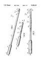
- FIG. 1is a perspective view of a laparoscopic instrument according to the invention
- FIG. 2is a side view of the instrument of FIG. 1 showing components therein in phantom;
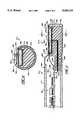
- FIG. 3is a partial sectional view of the instrument of FIG. 1;
- FIG. 4is an exploded perspective view of a crystal and associated crystal mount employed with the instrument of FIG. 1;
- FIG. 5is a sectional view taken through the plane 5--5 shown in FIG. 3;
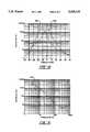
- FIG. 6is a graph showing the sensitivity of the instrument of FIG. 1 in counts per second with a distance of its detector component from a source of radiation;
- FIG. 7is a schematic representation of a human body showing a laparoscopic utilization of the instrument of the invention.
- FIG. 8is a schematic representation of a human body showing another utilization of the instrument of the invention.
- FIG. 9is a schematic representation of the instrument of FIG. 1 with the access tube thereof in broken fashion showing an opposite side thereof;
- FIG. 10is a chart showing the sensitivity of the instrument of the invention when employed for longitudinal and transverse scanning movement
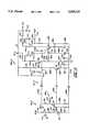
- FIGS. 11A and 11Bcombine as labeled to form a block diagram of the functional components of a signal treatment and control system associated with the instrument of the invention
- FIG. 12is an electrical schematic diagram of a preamplification function employed with the instrument of the invention.
- FIG. 13is a partial sectional view of an instrument according to the invention which is configured for detecting beta radiation emissions
- FIG. 14is a sectional view of the instrument of FIG. 13 taken through the plane 14--14 shown therein.
- locatorincludes a substance which preferentially concentrates at tumor sites by binding with a marker (the cancer cell or product of the cancer, for example) produced by or associated with neoplastic tissue or neoplasms.
- Appropriate locators todayprimarily include antibodies (whole and monoelonal), antibody fragments, chimefie versions of whole antibodies and antibody fragments, humanized versions thereof, as well as other tumor specific carriers, i.e. locators. It should be appreciated, however, that single chain antibodies (S CAs such as disclosed in U.S. Pat. No.
- RIGSradioimmunoguided surgical techniques
- the hand-held radiation detecting probe employed conventionally with the RIGS systemis described in U.S. Pat. No. 5,070,878 by Denen, issued Dec. 10, 1991, and assigned in common herewith.
- This probeutilizes a cadmium telluride crystal of adequate surface area which is mounted in a "forward looking" manner.
- the window component thereof at the tipis moved transversely along tissue being evaluated.
- the RIGS surgical approachis one wherein the extent of radiation emanating from a carrier located at neoplastic tissue is quite faint, it becomes necessary that the crystal be of adequate surface area to capture sufficient radiation emissions.
- the surgeonbecause of the rapid fall-off of radiation as the crystal surface is moved away from that tissue region in consequence of the inverse square law of radiation propagation, it is essential that the surgeon maintain a close proximity between the crystal surface behind the probe window and the radioactive tissue. In effect, this application of the inverse square law of radiation propagation aids in sharply delineating the extent or boundaries of neoplastic tissue.
- Collimatorsobviously are not employed with such a system where low energy radiation is involved inasmuch as they would not sharpen the location of radiation but would lessen the number of received emissions from the faint radiation source at the tumor site. From the laparoscopic surgical standpoint, it is necessary that the laparoscopic instrument be maneuverable, having an access tube or the like of diameter limited by the port of a cannula, for example, less than 12 mm. In the development of the instant invention, it was determined that the latter diametric constraint imposed unwanted limitations on the available surface area of a radiation detecting crystal such as cadmium telluride.
- the laparoscopic instrumentAs a forward looking laparoscopic adaptation of the radiation detecting probe was employed, in addition to the low count rates available with smaller diameter crystals, as the source of radiation was approached, usually in a longitudinal direction along the body cavity, instrument response diminishes as the crystal moves across the radiation source because of the shielding positioned about the crystal itself. Transverse movement of the instrument within the body cavity, for example, from a vertical orientation, represents a procedure with serious limitations to the extent it is not desirable.
- the laparoscopic instrumentis required to be configured within the diametric constraints associated with its insertion through a cannula and its somewhat horizontal maneuvering within the body cavity.
- the devicemust be capable of retaining a crystal such as cadmium-zinc-telluride for detection which has adequate surface area to achieve operationally effective radiation detecting sensitivity.
- This instrumentthen is called upon to locate neoplastic tissue through faint radiation emissions while being observed two-dimensionally with a television camera which also is inserted through a cannula into that same body cavity. In effect, the instrument is called upon to replace the surgeon's sense of touch and to support the surgeon's vision which now is restricted to two dimensions.
- Instrument 10includes a hand-grippable cylindrical base portion 12 to which an elongate accessing tube 14 is fixed.
- Accessing tube 14is of a length convenient to the surgeon for accessing those regions of the abdominal cavity intended for neoplastic tissue detection and localization. This length may, for example, be about 14 inches (36 cm) and extends to a tip 16. Inwardly from this tip 16 there is a detector support portion represented generally at 18 which extends to a union or joint represented at line 20.
- Tube 14is cylindrical, having an outer diameter, for example, of 11 mm such that it is suitable for insertion through a conventional 12 mm diameter cannula port.
- This cylindrical configurationextends through to the tip 16, however, the detector crystal mounted within the instrument 10 provides for "side looking" evaluation of impinging radiation.
- Thisis through a planar or flat window 22 located at the detector support portion 18 and which is seen to have a somewhat elongate rectangular peripheral shape.
- the crystal detectorwhich will be seen to be spaced but closely proximate the window 22 is operated in conjunction with signal treatment and control circuitry which ultimately is coupled through a console mounted connector (not shown) to the instrument 10 via a shielded flexible cable 24 extending from the hand-grippable base 12.
- the control and signal treatment componentsare contained within a console to which the cable 24 leads and which is located out of the sterile surgical field. However, some signal treatment components are necessitated at the instrument 10 itself.
- a crystal mount arrangementis shown in general in phantom at 26 located within the accessing tube 14 at the detector support portion 18.
- a preamplification stagerepresented generally at 28.
- a forward stage 28is positioned in proximity to crystal mount 26 and stage 28 then communicates, for example, with shielded cable as represented by dashed line 30 with a second or final preamplification stage shown in phantom at 32 which is mounted within the hand-grippable base 12. Cable 24 is electrically connected with this last amplification stage represented at 32.
- a crystal mount 34which is formed of a material selected to attenuate gamma radiation such as lead is provided which is inserted within the passageway of rod 14 at the detector support portion 18.
- This mount 34is seen to be generally cylindrical in shape with a flattened or truncated upwardly disposed surface 36 and a stepped down surface portion 38. Formed inwardly from the flat surface 36 is a rectangular crystal receiving and supporting cavity 40.
- the mount 34is seen to be positioned within a separate or discrete cylindrical tip component 42 of the tube 14.
- the component 42is seen to be flattened to define the window surface 22 and is slidably mounted over a stepped down surface 44 (FIG. 3) turned within tube 14. Retention of this tip component 42 upon the stepped down surface 44, for example, is provided using an electrically conductive epoxy cement. In this regard, the connection must be such as to assure no leakage of body fluids within the passageway 46 formed within tube 14.
- the upwardly disposed flat surface 36 of the mount 34is spaced in close adjacency with the underside of the window component 22 of tip component 42. This permits the positioning of a radiation responsive crystal as close as possible to that surface window 22.
- FIG. 3shows an opening or conduit 48 formed within the mount 34 which extends from an opening 50 within the rearward surface of mount 34 to a corresponding opening 54 at the bottom surface of cavity 40.
- the configuration thus depicted in connection with FIGS. 3-5is one intended for use in detecting locators labeled with gamma emitting radiation, and, particularly, emitted from 125 I which, for the surgical performance contemplated will be of very low energy level.
- Cadmium-zinc-telluride detecting crystalsare employed for this purpose. Such crystals are marketed by Aurora Technologies, Inc., San Diego, Calif.
- the crystal used for detectionit is desirable that the crystal used for detection have as large a surface area as is practical to improve counting efficiency.
- that active surface areawill be equivalent to the surface area of forward looking crystal mounts as are used in conventional RIGS surgery.
- a rectangular cadmium-zinc-telluride crystal 60is employed having a principal lengthwise dimension in parallel with the central axis 62 of the tube 14. Because cadmium telluride crystals exhibit microphonic (piezoelectric) effects, their mounting for the instant use requires a rigid avoidance of noise generated by rubbing or by the transmission of acoustical noise or the like into the crystal 60 from its mounting environment. To achieve this requisite mounting with an avoidance of microphonic induced noise, the cavity 40 is initially covered with an electrically insulative polymeric layer 64.
- the layer 64is formed of silicone, generally referred to as silicone rubber which is an elastomer in which the C linkages of a polymerized hydrocarbon are replaced by Si--O linkages. It is sold, for example, under the trademark "SILASTIC".
- the layer 64can be developed as a rectangular receptacle with a rectangular mold carrying a conventional mold release.
- a necessary electrical biasfor example at 60 v, is asserted at the rearward surface 66 of the crystal 60 by an electrical contact arrangement including multi-strand wire 68 seen extending from connection with a circuit board 70 in FIG. 3 and through the opening 50 of passageway 48 to opening 54 within the cavity 40.
- the plurality of strands of this wireare "spread out” over the polymeric layer 64 as seen in general at 72 in FIG. 4.
- an electrically conductive cushion layer 74positioned over the electrically insulative polymeric layer 64 at the bottom of the cavity 40 is an electrically conductive cushion layer 74 having a lower disposed surface 76 positioned over the strands 72 and upon the forwardly facing surface of layer 64.
- this lower disposed surface 76 of the cushion layer 74is adhered to the upper surface of the heat-stable silicone rubber. Additional amounts of the "SILASTIC" material may be used for this purpose.
- the electrically insulative elastomeric adhesiveretains its elastic properties over time and high temperature conditions.
- the electrically conductive cushion layer 74is provided as a non-woven TEFLON cloth which is carbon filled to the extent rendering it an effective conductor of electricity.
- the materialis a carbon containing stretched, highly crystalline, unsintered polytetrafiuoroethylene marketed under the trademark "Gore-Tex".
- the lower or rearward surface 82 of the cadmium-zinc-telluride crystal 60is freely abuttably positioned over the upwardly disposed surface 78 of electrically conductive cushion layer 74. No adhesive is employed in this union other than some of the silicone adhesive may migrate about the edge of the crystal 60 with beneficial effect.
- a thin elastomerically deformable sheet 86is stretched over the assembly including the upwardly disposed surface 84 of crystal 60. This compressibly urges the crystal downwardly to improve device performance.
- the thin sheet 86may be provided as a carbon-filled rubber and thus serves the second purpose of asserting necessary ground at the surface 84 of crystal 60. Note in this regard, that in stretching the sheet 86 over the crystal 60, it is fastened by machine screw and washer combination 88 at the forward or tip portion 90 of mount 34 seen in FIG. 3. The opposite end of the sheet 86 is similarly fastened to surface 38 of mount 34 by a machine screw and washer arrangement shown at 92 in FIGS. 3 and 4. Ground is conveyed to the sheet 86 from the lead mount 34 which, in turn, is coupled to ground through the forward stage 28 of the preamplifier function. Note that the circuit board 70 is seen attached to surface 38 of mount 34 with a screw 94.
- the upwardly disposed surface 84 of crystal 60is spaced from the underside of window 22 by a very small gap 96 to avoid acoustic or vibrationally induced noise.
- the distance from the outwardly disposed surface of window 22 to that upwardly disposed surface of crystal 60is quite small, being, for example, less than 2 mm. This permits the upwardly disposed surface 84 of crystal 60 to be positioned in very close proximity to the tissue under investigation. It is the flatness of the window 22 within the generally cylindrical instrument 10 which additionally permits this close positioning of the crystal to the tissue under investigation.
- Such distancing for the purpose of the operation of instrument 10is quite important in view of the low level of radiation involved and the noted approximate inverse square relationship of radiation propagation.
- FIG. 6the sensitivity of instrument 10 with respect to distance from a radiation source as may be encountered is revealed.
- the figureshows a curve 100 generated employing a 1 microcurie source ( 129 I). That source gradually is positioned further and further away from the upward surface 84 of crystal 60. Note that at a 2 mm distance, representing the equivalent of positioning the source right at the top surface of window 22, a count of about 3,000 counts per second is recognized. However, that initial count at the closest proximity to window 22 is seen by curve 100 to drop to 2,000 counts per second at the close distance of about 4 mm from the source. This rapid fall-off demonstrates the importance of the flatness of window 22 and its close positioning in adjacency with the top surface 84 of crystal 60.
- FIG. 7a schematic representation of the human anatomy is provided.
- the horizontal body 110is depicted having a liver region 112 in the vicinity of the rib cage.
- this regionis the gastrohepatic ligament with associated lymph nodes about the portal region of liver 112. These nodes are currently the subject of substantial interest on the part of those employing the RIGS system.
- Below the liver region 112is the colon.
- the colonis 120-200 cm long.
- the ascending colonis shown at 114 extending from the iliac fossa to the inferior surface of the liver 112.
- the transverse colon 116extends to the descending colon 118 thence to the sigmoid colon 120, the latter being suspended by its mesentery.
- the instrument 10is reproduced having been inserted through a cannula 122 located below the umbilicus.
- the detector support portion 18 of instrument 10is seen scanning somewhat horizontally both transversely and longitudinally a tumor region 124 while being observed by a laparoscope or video camera 126 which has been inserted through cannula 128 above the umbulicus.
- Other portstypically will be opened within the body 110 following pneumoperitoneum.
- FIG. 8shows a similar procedure in conjunction with a body representation utilizing the same numeration for identification as shown in FIG. 7.
- the instrument 10has been inserted through a cannula 140 below the umbilicus but positioned so as to permit scanning of the descending colon 118, particularly with respect to a tumor region represented at 142.
- the laparoscopic camera 126is inserted through a cannula 144 such that it may be positioned to observe the detector support portion 18 of instrument 10 as it scans about the region of interest 142. It has been found desirable to provide a visual televised readout of the rotational orientation of the instrument 10 during such procedures. Looking momentarily to FIG.
- a thin line 146may be seen to be engraved along the back surface of the accessing tube 14 including its detector support portion 18. This line may be observed by the video camera 126 and is seen to extend to the base portion 12 such that it may be observed also by the surgeon outside of the body cavity.
- the line 146is positioned along the instrument opposite the center of planar window 22.
- the output of the instrument 10 with respect to the noted transverse scanning and longitudinal scanningis revealed at respective curves 148 and 150.
- the same source and general set-up as described in connection with FIG. 6was used in a laboratory setting.
- the cadmium telluride crystal 60 employed with the instrument 10had dimensions of 7 mm ⁇ 14 mm.
- the sourcewas moved from the center position of the window 22 and outwardly therefrom. This center position, located at distance "0" shows a somewhat sharp peak in the resultant output in counts per second which may be expected from the shorter widthwise dimension of the crystal.
- curve 150the outer tip 16 of the probe was established as a 0 position, thus the curve 150 is shifted with respect to curve 148 and exhibits a wider peak response which is in keeping with the greater principal longitudinal dimension of the cadmium telluride crystal 60.
- FIG. 11A and 11Ba block diagrammatic representation of the signal treatment and control circuitry employed with instrument 10 is revealed.
- that crystal which is being employedfor example crystal 60 as labelled, is shown having one face coupled to ground through line 157, while the opposite, biased face thereof is coupled via lines 158 and 159 to a bias filter represented at block 160.
- Bias filter 160is part of the earlier-described forward preamplification stage 28 herein identified in FIG. 11A by a dashed boundary with the same numeration.
- the input to the filter 160is derived ultimately from cable 24 (FIG. 1) and is represented in FIG. 11A at line 161 as being applied through that cable again represented by numeral 24.
- Line 158corresponds with line 68 earlier described in connection with FIG. 3 and supplies an appropriate bias, for example, 60 v to the rearward surface of crystal 60. This bias emanates from a power supply shown at block 162 in FIG. 11B and represented at line 163.
- Line 158 from crystal 60is shown extending to an integrator stage 164 of the first preamplifier stage 28.
- the integrated valuation of a detected radiation disturbance or charge categorized signalthen is shown directed as represented by line 165a to a driver-amplification network shown at block 166.
- Line 165aadditionally is a part of the shielded cable 30 extending through the passageway 46 of access tube 14 to the second preamplification stage 32 within base 12 as described in connection with FIG. 2.
- Cable 30also may carry ground and +12 v supply as shown, respectively, at lines 165b and 165c.
- the noted 12 v power supply as represented at line 165cis derived for the driver amplifier stage 166 from the power supply 162 (FIG. 11B) as represented at line 167 which, as shown in FIG.
- 11Ais directed to a probe current network represented by block 168.
- the network 168develops signals, for example, determining whether the probe instrument 10 has been properly connected to a console based control system described in detail in U.S. Pat. No. 4,801,803 (not shown).
- Delivery of the 12 v power supply for the preamplifier stage 32is represented at line 170 as extending to the driver-amplifier 166 via cable 24 and line 171.
- Ground to the instrument 10also is developed from the power supply block 162 as represented at line 172 shown in FIG. 11A as extending to cable 24 and via line 173 to the driver-amplification stage 166.
- the output of the driver-amplification stage 166is represented at line 174 extending through the cable 24 and then being represented as line 175 to the input of a normalizing amplifier represented at block 176.
- the network represented by block 176functions to amplify or attenuate, i.e. scale the noise characteristic of any given instrument 10 and normalize the value thereof or render it consistent for later comparison stages.
- the 27 key energy level gamma ray generated pulses in a system employing 125 Iwill be about five times higher than noise levels.
- Normalizing amplifier network 176will establish those noise levels at some predetermined level, for example, 200 millivolts, and the resultant proportional valid gamma related pulses will become about 1 v high for purposes of ensuing comparison functions.
- the amplifier network at block 176is controlled from a digital-to-analog converter network represented at block 177 via line 178.
- Network 177is controlled from line 179 extending, as shown in FIG. 11B, to block 180 representing a microcomputer network.
- the normalized output developed from network 176is presented along lines 181 and 182 to a noise averager circuit as represented at block 183.
- This network 183determines an average amplitude value for the noise of a given system with a given instrument 10 and provides a corresponding signal as represented at line 184 (noise amp) which is employed as above described as information used by the microcomputer 180.
- This informationin addition to being employed with the normalizing amplifier network represented at block 176, may be used to develop a low window valuation for the comparison function.
- Line 182also extends via line 186 to a pulse acquire network represented at block 188.
- This networkfunctions, when activated, by the microcomputer represented at block 180, to acquire the value of the highest pulse amplitude witnessed at line 186. Periodically, this information then is transmitted to the microcomputer at block 180 as represented by line 190. Representing a form of peak detector, the network is sometimes referred to as a "snapshot circuit".
- a buffer amplifierwhich will provide at line 1.96 an output representing received pulses which may be made available to the system, for example, at a console (not shown).
- Line 181extends, as shown at FIG. 11B, at line 198, to one input of an upper window comparator represented at block 200 and a lower window comparator illustrated at block 202.
- the threshold level for comparative purposes employed by the network at block 202is shown asserted from line 204 and, preferably, is developed by the logic of microcomputer network 180 at a level just above the noise amplitude signals generated from line 184. Of course, manual setting of such windows can be carried out. In similar fashion, the upper window of acceptance for valid radiation interaction is established from a corresponding line 206. This threshold setting may be made from the information taken from pulse acquire network 188.
- the upper window and lower window threshold selectionsare made under the control of the microcomputer network at block 180 which controls the digital-to-analog network shown at block 177. It is the characteristic of such networks as at block 177 to provide an output which is comprised, for example, of 256 steps of varying amplitude. The percentage of incrementation from step to step will vary somewhat over a range of voltage values provided. Accordingly, the outputs from this conversion network at block 177, as shown at lines 208 and 210 are directed to squarer networks shown, respectively, at blocks 212 and 214. These networks function to square the current outputs at lines 208 and 210 and thus achieve a uniform percentage incrementation of the threshold defining outputs at lines 204 and 206.
- the outputs of the comparator networks shown at blocks 200 and 202represent candidate pulses which may be above or below the given thresholds and are identified as being presented as "UW pulse” and "LW pulse” along respective lines 216 and 218. These lines are shown directed to a real time pulse discriminator network represented at block 220 which carries out Boolean logic to determine the presence or absence of valid pulses. Valid pulses are introduced to the microcomputer network 180 as represented by line 222.
- the microcomputer network represented at block 180performs under a number of operational modes to provide both audio and visual outputs to aid the surgeon in locating and differentiating tumorous tissue.
- a volume control functionmay be asserted with amplitude variations controlled from a solid-state form of potentiometer represented at line 228 and block 230.
- Control to potentiometer 230is represented at line 229.
- a "siren" type of frequency variationmay be asserted as represented at line 232 to an audio amplification circuit represented at block 234 for driving a speaker as represented at 236 and line 238.
- the frequency output from speaker 236increases as the instrument 10 is moved closer to the situs of concentrated radiation.
- conventional clicks and beepscan be provided at the option of the operator.
- the microcomputer network 180as represented by bus defining arrow 240 and block 242 also addresses an input-output network which, as represented at bus arrow 244, functions to provide a pulse count output of varying types as well as outputs representing volume levels, pulse height, noise levels, and battery status. These outputs are provided in visual format at a visual display represented at block 245.
- the input-output function represented at block 242provides appropriate scanning of switches or the like may be employed with the control system and are represented by block 241 and bus input arrow 243.
- the microcomputer network at block 180functions to control a light emitting diode drive network represented by block 246 from line 248.
- the drive network represented at block 246is shown providing an input, as represented by line 250, to a light emitting diode (LED) display as represented by block 251.
- a serial output port of conventional varietyalso may be provided with the system, such ports being represented at block 252 being addressed from the microcomputer represented at block 180 from line 254 and having output and input components represented by arrow 256.
- a real time clock-calendar having a non-volatile memoryalso may be provided in conjunction with the functions of the microcomputer network 180 as represented by block 258 and bus-arrow 260. Further, the microcomputer may be employed to monitor the performance of the power supply represented at block 162.
- the power supplyalso provides a +5 source for the logic level components of the circuit as represented by line 268; a -5 source at line 270, as well as a -9 v source at line 272 for purposes of display drive, and finally, a 2.5 v reference as represented at line 274 to provide reference input for the preamplification analog circuitry.
- the microcomputer network as represented at block 180also provides an input to the digital-to-analog conversion network represented at block 177 which corresponds with the instantaneous pulse rate and this information is conveyed to a pulse rate and this information is conveyed to a pulse rate amplifier network represented at block 276 via line 278.
- the resultant output, as represented at line 280may be provided, for example, at a convenient location upon a console.
- This circuit represented at block 276also may be employed to generate a calibrating pulse for testing the downstream components of the system.
- the microcomputer represented at block 180applies a predetermined pulse level through the digital-to-analog conversion network at block 177 for presentation to the amplifier network represented at block 276.
- the resultant output at line 282is selectively switched, as represented by block 284, to define pulse width from the microcomputer input at line 286 to the calibrating pulse at line 288.
- the dual stage preamplification function employed with the instrument 10is represented generally at 290.
- the preamplification function 290includes the earlier-described forward stage 28 which is coupled by a shielded connector 30 to a second stage again represented in general at 32.
- the circuit 290is seen performing in conjunction with a radiation detecting crystal herein again represented at 60 and is seen to include a bias filtering component as earlier described and again represented in general at 160 as well as an integrator component 164 again represented by that numeration.
- the components of the cable 30are represented as described in conjunction with FIG. 11A at lines 165a-165c. Bias, as before, is shown being provided from line 161.
- This biasis seen to be asserted through one side of crystal 30 through the bias filter 160 comprised of resistors R1, R2, and a capacitor C1.
- Capacitor C1provides a local filter to remove any spurious noise which may be engendered in the line transmitting bias.
- the opposite face of crystal 60is coupled to ground as represented by earlier-described line 165b.
- Crystal bias resistor R2is provided having a large resistance value, for example, about 50 megohms, a level selected to avoid absorbing current disturbances from the crystal.
- the input signal to the integration stage 164is asserted through coupling capacitor C2 and line 292 to the gate input terminal of a N-channel junction field effect transistor (JFET) Q1.
- JFETjunction field effect transistor
- Line 292also is coupled via line 294 and bias resistor R3 to ground at line 165b.
- the resistance value at resistor R3is selected commensurately with the selection of resistance for resistor R2, preferably about 200 megaohms to avoid signal absorption. Generally, the resistance for this component will be selected between about 10 to 10,000 megaohms.
- the transistor Q1performs with stray capacitance and, additionally, in effect, operates as a source follower charge amplifier, its purpose being to achieve an impedance transformation from a very high impedance gate suited to low current and low noise. In general, the JFET structure exhibits lowest current noise at the room temperature operating conditions contemplated for the present instrument.
- the devicetends to create a large current disturbance at its source terminal at line 296.
- Line 296extends through a source load resistor R4 to ground line 165b.
- the resistor R4functions as a d.c. current return device.
- the drain terminal of transistor Q1is coupled to +12 supply at line 165c while the same terminal is decoupled or isolated by a filter comprised of capacitor C4 and resistor R5.
- the charge categorized output of stage 28 at line 165ais transmitted along the cable 30 and line 165a to the base of NPN, bipolar transistor Q2.
- Transistor Q2performs a voltage amplification and a singular bipolar component is elected for this function inasmuch as such devices exhibit low voltage noise characteristics at room temperature. Additionally, the devices have a higher amplification factor availability than corresponding field effect transistors.
- the degree of amplification achievable with stage Q2is related to the impedance exhibited with respect to its emitter and collector, i.e. the value of the collector load impedance divided by the emitter impedance.
- the emitter of transistor Q2is coupled via line 298 to ground through resistor R6 and is by-passed to ground via lines 298 and 300 through capacitor C5.
- the latter componentexhibits relatively low impedance on the order of 25 ohms at the frequencies of interest.
- the collector of transistor Q2is coupled with +12 supply via line 302.
- Line 302is associated with a relatively high resistance value resistor R7 which is in series with a resistor R8.
- an NPN transistor Q3is coupled in a "bootstrap" circuit arrangement to raise its effective collector impedance to transistor Q2.
- the base of transistor Q3is coupled via line 304 to line 302, while the collector thereof at line 306 is coupled to supply line 171 in conjunction with a decoupling filter comprised of resistor R9 and capacitor C7.
- the emitter of transistor Q3is coupled to line 308 to ground through resistor R10 as well as via line 310 incorporating resistor R11 and capacitor C6. This line 310 extends to a position intermediate resistors R7 and R8.
- Transistor Q3functions as an emitter follower, feeding the noted junction between resistors R7 and R8 through resistor R11 and capacitor C6 in bootstrapping fashion.
- Resistor R11is incorporated in the circuit to damp the positive feedback and lower gain otherwise elevated due to the stage separation of the preamplification function 290.
- Transistors Q2 and Q3may be considered to participate in the integration function 164, however, for the instant description, they are incorporated within what has been referred to as a driver amplifier function 166.
- the signal at line 308is applied through resistor R12 and capacitor C9 to the base of an NPN transistor Q4 which forms one component of an amplification stage in conjunction with PNP transistor Q5.
- This A.C. voltage amplifiercomprises few components and exhibits high gain and broad bandwidth characteristics. Because the gamma ray interaction at crystal 60 will exhibit a frequency disturbance spectrum ranging from about 50 KHz to 200 KHz, the frequency response of this amplification component is tailored accordingly. For example, the high end roll-off of the response is established by resistor R10 within line 308 and capacitor C8 within line 310.
- a voltage bias to the base of transistor Q4is provided via line 312 from supply following its division by divider resistors R13 and R14. This bias input, amounting to about 1/4 of the supply voltage is treated by the filter combination of resistor R9 and capacitor C7.
- the 12 power supplyadditionally is filtered by a pi filter comprised of capacitors C10 and C12 along with resistor R15 as coupled within line 314.
- Line 314is seen to extend via line 316 to the emitter of transistor Q5 and through resistor R16 to the base thereof as well as to the collector of transistor Q4.
- the emitter of transistor Q4extends via lines 318, 320, and 322 to resistor R17 and the collector of transistor Q5 as well as to resistor R18.
- the output of the preamplifier function 290is provided at earlier-described line 174 incorporating resistor R19.
- the gain of this output stageis set by resistor R20 in conjunction with resistor R17, while capacitor C11 aids in the setting of low frequency roll-off for the amplifier component.
- the high frequency roll-off characteristicis further aided by the combination of resistor R12 and capacitor C13, the latter component being coupled between line 324 and ground via line 326.
- Low end roll-off characteristics for the amplification stagefurther are aided by the combination of capacitor C5 and resistor R6.
- radioisotopes emitting beta radiationadditionally can be used in conjunction with the laparoscopic instrument of the invention.
- the instrumentwill employ a crystal semi-conductor responsive to beta radiation emissions or positrons.
- Beta radiation responsive devices intended for interoperative useare disclosed, for example, in U.S. Pat. No. 5,008,546.
- the instrument 10is revealed having an access tube 14 as before incorporating a passageway 46 and at least one initial stage of a pre-amplification function as represented at 28 in conjunction with a thin elongate circuit board 340.
- the detector support portion 18 of the instrument 10now is configured somewhat differently, having an outer cylindrical support housing 342 which may be formed of aluminum or plastic and which is attached to a surface 344 of reduced diameter at the end of tube 14.
- the housing 342is attached by an epoxy adhesive which, for the present embodiment, should be electrically conductive.
- Housing 342forms a tip 346 and extending inwardly from that tip in generally parallel relationship with the central axis 348 of the instrument is a rectangular opening 350 defined by the peripheral edges as at 352.
- a thin polymeric cover 354having a thickness, for example, of 4 mils and being vapor coated with aluminum to provide opacity within the interior of the housing 342 while remaining substantially transmissive to beta radiation to define a window at opening 350.
- the cover 354may be provided as a thin polyester, for example, such as that sold under the trademark "Mylar".
- a detector or crystal componentis selected which is responsive to beta or positron emissions while remaining non-responsive to gamma radiation.
- Such a componentmay be provided as a silicon crystal configured with a PN junction, the latter being reverse biased to evoke a depletion layer.
- Such a crystalis represented in the figure at 356 positioned within a rectangular cavity 358 formed within a crystal mount 360.
- Mount 360is fashioned of a material which attenuates beta radiation without the generation of secondary X-rays. Accordingly, the device is made of a plastic or the like and specifically not a heavy metal such as lead. A polycarbonate may be used for the purpose of device 360.
- Mount 360appears quite similar to that described at 34 having a flat upper surface 362 which is again stepped down at 364 for the purpose of supporting elongate circuit board 340 through a screw connection 366.
- a conduit 368extends through mount 360 from an opening 370 within the passageway 46 to an opening 372 at the bottom center of cavity 358.
- Silicon device 356will not exhibit the microphonic noise effects of a cadmium telluride device, consequently, its mounting is somewhat simplified.
- a silicone or silicone rubber layer 374is formed along the walls of cavity 358, for example, as before, utilizing a mold and mold release. Connection of the lower crystal surface 380 of silicon crystal 356 with a biasing lead as at 376 may be provided through an electrically conductive adhesive or by thermal compressive bonding.
- the ground connection to the upper surface 382 of crystal 356may be provided by an aluminum wire as at 378. Aluminum is used for this purpose to avoid X-ray generation and may be coupled into surface 382 by thermal compression bonding.
Landscapes
- Health & Medical Sciences (AREA)
- Life Sciences & Earth Sciences (AREA)
- Engineering & Computer Science (AREA)
- Biomedical Technology (AREA)
- Medical Informatics (AREA)
- General Health & Medical Sciences (AREA)
- Physics & Mathematics (AREA)
- Public Health (AREA)
- Veterinary Medicine (AREA)
- Nuclear Medicine, Radiotherapy & Molecular Imaging (AREA)
- Animal Behavior & Ethology (AREA)
- Radiology & Medical Imaging (AREA)
- Heart & Thoracic Surgery (AREA)
- Pathology (AREA)
- Optics & Photonics (AREA)
- Molecular Biology (AREA)
- High Energy & Nuclear Physics (AREA)
- Surgery (AREA)
- Biophysics (AREA)
- Anesthesiology (AREA)
- General Physics & Mathematics (AREA)
- Spectroscopy & Molecular Physics (AREA)
- Hematology (AREA)
- Dermatology (AREA)
- Endoscopes (AREA)
- Nuclear Medicine (AREA)
- Radiation-Therapy Devices (AREA)
- Instruments For Viewing The Inside Of Hollow Bodies (AREA)
- Surgical Instruments (AREA)
- Analysing Materials By The Use Of Radiation (AREA)
- Geophysics And Detection Of Objects (AREA)
- Materials For Medical Uses (AREA)
- Medicines Containing Antibodies Or Antigens For Use As Internal Diagnostic Agents (AREA)
- Piezo-Electric Transducers For Audible Bands (AREA)
Abstract
Description
Claims (21)
Priority Applications (15)
| Application Number | Priority Date | Filing Date | Title |
|---|---|---|---|
| US07/992,617US5429133A (en) | 1992-12-18 | 1992-12-18 | Radiation responsive laparoscopic instrument |
| CA002110857ACA2110857C (en) | 1992-12-18 | 1993-12-07 | Radiation responsive laparoscopic instrument |
| IL107920AIL107920A (en) | 1992-12-18 | 1993-12-07 | Radiation responsive laparoscopic instrument |
| EP93630100AEP0603110B1 (en) | 1992-12-18 | 1993-12-09 | Radiation responsive laparoscopic instrument |
| AT93630100TATE175855T1 (en) | 1992-12-18 | 1993-12-09 | RADIATION RESPONSIVE LAPAROSCOPIC INSTRUMENT |
| ES93630100TES2128408T3 (en) | 1992-12-18 | 1993-12-09 | RADIATION SENSITIVE LAPAROSCOPIC INSTRUMENT. |
| DE69323166TDE69323166T2 (en) | 1992-12-18 | 1993-12-09 | Laparoscopic instrument responsive to radiation |
| AU52594/93AAU669236B2 (en) | 1992-12-18 | 1993-12-16 | Radiation responsive laparoscopic instrument |
| KR1019930028464AKR100186784B1 (en) | 1992-12-18 | 1993-12-18 | Radiation Reactive Laparoscopic Instruments |
| JP5344950AJP2816642B2 (en) | 1992-12-18 | 1993-12-20 | Radiation source detection and localization device |
| MX9400056AMX9400056A (en) | 1992-12-18 | 1994-01-03 | RADIATION SENSITIVE LAPAROSCOPIC INSTRUMENT. |
| US08/214,814US5383456A (en) | 1992-12-18 | 1994-03-17 | Radiation-based laparoscopic method for determining treatment modality |
| IL112902AIL112902A (en) | 1992-12-18 | 1995-03-07 | Radiation-based laparoscopic method for determining treatment modality |
| AU14881/95AAU678334B2 (en) | 1992-12-18 | 1995-03-15 | Radiation-based laparoscopic method for determining treatment modality |
| CA002144821ACA2144821A1 (en) | 1992-12-18 | 1995-03-16 | Radiation-based laparoscopic method for determining treatment modality |
Applications Claiming Priority (2)
| Application Number | Priority Date | Filing Date | Title |
|---|---|---|---|
| US07/992,617US5429133A (en) | 1992-12-18 | 1992-12-18 | Radiation responsive laparoscopic instrument |
| US08/214,814US5383456A (en) | 1992-12-18 | 1994-03-17 | Radiation-based laparoscopic method for determining treatment modality |
Related Child Applications (1)
| Application Number | Title | Priority Date | Filing Date |
|---|---|---|---|
| US08/214,814Continuation-In-PartUS5383456A (en) | 1992-12-18 | 1994-03-17 | Radiation-based laparoscopic method for determining treatment modality |
Publications (1)
| Publication Number | Publication Date |
|---|---|
| US5429133Atrue US5429133A (en) | 1995-07-04 |
Family
ID=26909391
Family Applications (2)
| Application Number | Title | Priority Date | Filing Date |
|---|---|---|---|
| US07/992,617Expired - LifetimeUS5429133A (en) | 1992-12-18 | 1992-12-18 | Radiation responsive laparoscopic instrument |
| US08/214,814Expired - LifetimeUS5383456A (en) | 1992-12-18 | 1994-03-17 | Radiation-based laparoscopic method for determining treatment modality |
Family Applications After (1)
| Application Number | Title | Priority Date | Filing Date |
|---|---|---|---|
| US08/214,814Expired - LifetimeUS5383456A (en) | 1992-12-18 | 1994-03-17 | Radiation-based laparoscopic method for determining treatment modality |
Country Status (11)
| Country | Link |
|---|---|
| US (2) | US5429133A (en) |
| EP (1) | EP0603110B1 (en) |
| JP (1) | JP2816642B2 (en) |
| KR (1) | KR100186784B1 (en) |
| AT (1) | ATE175855T1 (en) |
| AU (2) | AU669236B2 (en) |
| CA (2) | CA2110857C (en) |
| DE (1) | DE69323166T2 (en) |
| ES (1) | ES2128408T3 (en) |
| IL (2) | IL107920A (en) |
| MX (1) | MX9400056A (en) |
Cited By (33)
| Publication number | Priority date | Publication date | Assignee | Title |
|---|---|---|---|---|
| US5495111A (en)* | 1994-10-26 | 1996-02-27 | Neoprobe Corporation | Crystal array based localizer for tissue sampling |
| WO1997003369A1 (en)* | 1995-07-13 | 1997-01-30 | Pol.Hi.Tech. S.R.L. | Surgical probe for laparoscopy or intracavitary tumour localization |
| US5810806A (en)* | 1996-08-29 | 1998-09-22 | Ethicon Endo-Surgery | Methods and devices for collection of soft tissue |
| US5857463A (en)* | 1995-10-13 | 1999-01-12 | Neoprobe Corporation | Remotely controlled apparatus and system for tracking and locating a source of photoemissions |
| US6076009A (en)* | 1997-05-05 | 2000-06-13 | The University Of Michigan | Solid state beta-sensitive surgical probe |
| US6132372A (en) | 1993-05-13 | 2000-10-17 | Synectics Medical, Incorporated | Measurement of gastric emptying and gastrointestinal output |
| US6144876A (en)* | 1998-10-23 | 2000-11-07 | Neoprobe Corporation | Scanning a radiation source with a count rate output derived with a dynamic window analysis |
| WO2000033105A3 (en)* | 1998-11-30 | 2000-11-16 | Carewise Medical Products Corp | Minimally invasive surgical instrument for tissue identification, dislodgment and retrieval and methods of use |
| US6161912A (en)* | 1996-04-10 | 2000-12-19 | Seiko Epson Corporation | Method of maintaining and controlling the helmholtz resonant frequency in an ink jet print head |
| US6204505B1 (en)* | 1998-10-06 | 2001-03-20 | Neoprobe Corporation | Surgical probe apparatus and system |
| US6222193B1 (en) | 1998-10-06 | 2001-04-24 | Neoprobe Corporation | Radiation responsive surgical probe apparatus |
| US6242741B1 (en) | 1998-10-23 | 2001-06-05 | United States Surgical Corporation | Radiation detection apparatus |
| US6259095B1 (en) | 1998-10-23 | 2001-07-10 | Neoprobe Corporation | System and apparatus for detecting and locating sources of radiation |
| US6272373B1 (en) | 1998-10-23 | 2001-08-07 | Neoprobe Corporation | Scanning system and method for locating sources of radiation emission |
| US6280398B1 (en) | 1999-10-18 | 2001-08-28 | Ethicon Endo-Surgery | Methods and devices for collection of soft tissue |
| US20030152513A1 (en)* | 2001-09-06 | 2003-08-14 | Imetrix, Inc. | Intravascular delivery of therapeutic and imaging agents to stressed and apoptotic cells using annexin V as a targeting vector |
| US20040075058A1 (en)* | 2002-10-22 | 2004-04-22 | Ira Blevis | Gamma camera |
| US6782289B1 (en) | 1999-10-08 | 2004-08-24 | The Board Of Trustees Of The Leland Stanford Junior University | Methods and apparatus for characterizing lesions in blood vessels and other body lumens |
| US20060178577A1 (en)* | 2000-01-04 | 2006-08-10 | Iwanczyk Jan S | Intravascular imaging detector |
| US20060212044A1 (en)* | 2003-10-02 | 2006-09-21 | University Of Florida Research Foundation, Inc. | Frameless stereotactic guidance of medical procedures |
| US20070021641A1 (en)* | 2005-07-20 | 2007-01-25 | Clear Vascular, Inc. | Methods and compositions for treating luminal inflammatory disease |
| US20070071676A1 (en)* | 2005-09-26 | 2007-03-29 | Clear Vascular, Inc. | Methods and Therapies for Treating Inflammatory Conditions with Exposed Collagen |
| US20100321192A1 (en)* | 2009-06-19 | 2010-12-23 | Vivant Medical, Inc. | Microwave Ablation Antenna Radiation Detector |
| US20110213241A1 (en)* | 2009-06-19 | 2011-09-01 | Vivant Medical, Inc. | Laparoscopic Port with Microwave Rectifier |
| US8344331B1 (en) | 2009-03-20 | 2013-01-01 | Devicor Medical Products, Inc. | K-alpha probe for detection of photon emissions |
| US9139316B2 (en) | 2010-12-29 | 2015-09-22 | Cardinal Health 414, Llc | Closed vial fill system for aseptic dispensing |
| WO2015160770A1 (en) | 2014-04-15 | 2015-10-22 | The Regents Of The University Of California | Bi-terminal pegylated integrin-binding peptides and methods of use thereof |
| US9417332B2 (en) | 2011-07-15 | 2016-08-16 | Cardinal Health 414, Llc | Radiopharmaceutical CZT sensor and apparatus |
| US9480962B2 (en) | 2011-07-15 | 2016-11-01 | Cardinal Health 414, Llc | Modular cassette synthesis unit |
| US10906020B2 (en) | 2011-07-15 | 2021-02-02 | Cardinal Health 414, Llc | Systems, methods and devices for producing, manufacturing and control of radiopharmaceuticals |
| US11185601B2 (en)* | 2016-06-13 | 2021-11-30 | The Regents Of The University Of California | Alpha(v)beta(6) integrin-binding peptides and methods of use thereof |
| WO2025160502A1 (en) | 2024-01-26 | 2025-07-31 | The Regents Of The University Of California | Peptide receptor radionuclide therapy |
| WO2025191096A1 (en) | 2024-03-14 | 2025-09-18 | Bicycletx Limited | Bicyclic peptide |
Families Citing this family (61)
| Publication number | Priority date | Publication date | Assignee | Title |
|---|---|---|---|---|
| US5482040A (en)* | 1994-04-14 | 1996-01-09 | The Ohio State University Research Foundation | Biostaging of adenocarcinomas utilizing radiolabeled tumor-associated glycoprotein antibodies |
| US5732704A (en)* | 1995-10-13 | 1998-03-31 | Neoprobe Corporation | Radiation based method locating and differentiating sentinel nodes |
| EP0973433A1 (en)* | 1995-10-16 | 2000-01-26 | Carl G. Coin | Computed tomographic colonscopy |
| US5682888A (en)* | 1996-06-13 | 1997-11-04 | Neoprobe Corporation | Apparatus and system for detecting and locating photon emissions with remote switch control |
| US5928150A (en)* | 1997-10-04 | 1999-07-27 | Neoprobe Corporation | System for locating and detecting a source of photon emissions |
| US6205352B1 (en) | 1997-11-19 | 2001-03-20 | Oncology Innovations, Inc. | Sentinel node identification using non-isotope means |
| US6077508A (en)* | 1998-03-23 | 2000-06-20 | American Diagnostica Inc. | Urokinase plasminogen activator receptor as a target for diagnosis of metastases |
| JP3380175B2 (en)* | 1998-09-24 | 2003-02-24 | アロカ株式会社 | Radiation measuring instrument |
| US6331703B1 (en) | 1999-03-12 | 2001-12-18 | Ethicon Endo-Surgery, Inc. | Guidance method for radiation detection |
| US6346706B1 (en)* | 1999-06-24 | 2002-02-12 | The Regents Of The University Of Michigan | High resolution photon detector |
| US7373197B2 (en)* | 2000-03-03 | 2008-05-13 | Intramedical Imaging, Llc | Methods and devices to expand applications of intraoperative radiation probes |
| US6510336B1 (en) | 2000-03-03 | 2003-01-21 | Intra Medical Imaging, Llc | Methods and devices to expand applications of intraoperative radiation probes |
| US6602488B1 (en) | 2000-03-03 | 2003-08-05 | Intramedical Imaging, Llc | Use of radiopharmaceuticals and intraoperative radiation probe for delivery of medicinal treatments |
| US8055329B2 (en)* | 2001-01-22 | 2011-11-08 | Spectrum Dynamics Llc | Ingestible device for radioimaging of the gastrointestinal tract |
| US8909325B2 (en)* | 2000-08-21 | 2014-12-09 | Biosensors International Group, Ltd. | Radioactive emission detector equipped with a position tracking system and utilization thereof with medical systems and in medical procedures |
| US8565860B2 (en)* | 2000-08-21 | 2013-10-22 | Biosensors International Group, Ltd. | Radioactive emission detector equipped with a position tracking system |
| US8489176B1 (en) | 2000-08-21 | 2013-07-16 | Spectrum Dynamics Llc | Radioactive emission detector equipped with a position tracking system and utilization thereof with medical systems and in medical procedures |
| US8036731B2 (en)* | 2001-01-22 | 2011-10-11 | Spectrum Dynamics Llc | Ingestible pill for diagnosing a gastrointestinal tract |
| JPWO2003010557A1 (en)* | 2001-07-26 | 2004-11-18 | 日本メジフィジックス株式会社 | Radiation detector |
| CA2642135C (en) | 2001-11-21 | 2013-04-09 | E-Z-Em, Inc. | Device, system, kit or method for collecting effluent from an individual |
| US20040082863A1 (en)* | 2002-03-15 | 2004-04-29 | Mcgreevy James | Device and method for the photodynamic diagnosis of tumor tissue |
| US20040116807A1 (en)* | 2002-10-17 | 2004-06-17 | Roni Amrami | Blood vessels wall imaging catheter |
| US20040204646A1 (en)* | 2002-11-04 | 2004-10-14 | V-Target Technologies Ltd. | Intracorporeal-imaging head |
| EP1573495B1 (en) | 2002-11-04 | 2009-11-04 | Spectrum Dynamics LLC | Apparatus and methods for imaging and attenuation correction |
| US7968851B2 (en) | 2004-01-13 | 2011-06-28 | Spectrum Dynamics Llc | Dynamic spect camera |
| US8571881B2 (en) | 2004-11-09 | 2013-10-29 | Spectrum Dynamics, Llc | Radiopharmaceutical dispensing, administration, and imaging |
| US9470801B2 (en)* | 2004-01-13 | 2016-10-18 | Spectrum Dynamics Llc | Gating with anatomically varying durations |
| WO2006051531A2 (en)* | 2004-11-09 | 2006-05-18 | Spectrum Dynamics Llc | Radioimaging |
| WO2006054296A2 (en)* | 2004-11-17 | 2006-05-26 | Spectrum Dynamics Llc | Methods of detecting prostate cancer |
| CN1981210A (en)* | 2004-01-13 | 2007-06-13 | 光谱动力学有限责任公司 | Multi-dimensional image reconstruction |
| US8586932B2 (en) | 2004-11-09 | 2013-11-19 | Spectrum Dynamics Llc | System and method for radioactive emission measurement |
| WO2008010227A2 (en)* | 2006-07-19 | 2008-01-24 | Spectrum Dynamics Llc | Imaging protocols |
| WO2007054935A2 (en)* | 2005-11-09 | 2007-05-18 | Spectrum Dynamics Llc | Dynamic spect camera |
| WO2005112895A2 (en)* | 2004-05-20 | 2005-12-01 | Spectrum Dynamics Llc | Ingestible device platform for the colon |
| EP1766550A2 (en) | 2004-06-01 | 2007-03-28 | Spectrum Dynamics LLC | Methods of view selection for radioactive emission measurements |
| EP1778957A4 (en) | 2004-06-01 | 2015-12-23 | Biosensors Int Group Ltd | OPTIMIZING THE MEASUREMENT OF RADIOACTIVE EMISSIONS IN SPECIFIC BODY STRUCTURES |
| US8423125B2 (en) | 2004-11-09 | 2013-04-16 | Spectrum Dynamics Llc | Radioimaging |
| US9943274B2 (en) | 2004-11-09 | 2018-04-17 | Spectrum Dynamics Medical Limited | Radioimaging using low dose isotope |
| US8615405B2 (en) | 2004-11-09 | 2013-12-24 | Biosensors International Group, Ltd. | Imaging system customization using data from radiopharmaceutical-associated data carrier |
| US9316743B2 (en) | 2004-11-09 | 2016-04-19 | Biosensors International Group, Ltd. | System and method for radioactive emission measurement |
| WO2008059489A2 (en) | 2006-11-13 | 2008-05-22 | Spectrum Dynamics Llc | Radioimaging applications of and novel formulations of teboroxime |
| EP1844351A4 (en) | 2005-01-13 | 2017-07-05 | Biosensors International Group, Ltd. | Multi-dimensional image reconstruction and analysis for expert-system diagnosis |
| US8837793B2 (en) | 2005-07-19 | 2014-09-16 | Biosensors International Group, Ltd. | Reconstruction stabilizer and active vision |
| EP1908011B1 (en)* | 2005-07-19 | 2013-09-04 | Spectrum Dynamics LLC | Reconstruction stabilizer and active vision |
| US8644910B2 (en)* | 2005-07-19 | 2014-02-04 | Biosensors International Group, Ltd. | Imaging protocols |
| ES2556974T3 (en)* | 2005-08-12 | 2016-01-21 | Jiang Liu | Devices for lymphatic system orientation |
| US7806850B2 (en) | 2005-10-24 | 2010-10-05 | Bracco Diagnostics Inc. | Insufflating system, method, and computer program product for controlling the supply of a distending media to an endoscopic device |
| US8204500B2 (en) | 2005-12-28 | 2012-06-19 | Starhome Gmbh | Optimal voicemail deposit for roaming cellular telephony |
| US8894974B2 (en)* | 2006-05-11 | 2014-11-25 | Spectrum Dynamics Llc | Radiopharmaceuticals for diagnosis and therapy |
| WO2008075362A2 (en)* | 2006-12-20 | 2008-06-26 | Spectrum Dynamics Llc | A method, a system, and an apparatus for using and processing multidimensional data |
| EP2209416A4 (en) | 2007-10-15 | 2014-05-14 | Univ Maryland | APPARATUS AND METHOD FOR ANALYZING THE INTESTINES OF A PATIENT |
| US8521253B2 (en)* | 2007-10-29 | 2013-08-27 | Spectrum Dynamics Llc | Prostate imaging |
| US9808345B2 (en) | 2008-07-24 | 2017-11-07 | Iorthopedics, Inc. | Resilient arthroplasty device |
| US8338788B2 (en) | 2009-07-29 | 2012-12-25 | Spectrum Dynamics Llc | Method and system of optimized volumetric imaging |
| WO2011091005A2 (en) | 2010-01-22 | 2011-07-28 | Grotz R Thomas | Resilient knee implant and methods |
| US10307257B2 (en) | 2010-01-22 | 2019-06-04 | Iorthopedics, Inc. | Resilient knee implant and methods |
| WO2013033447A2 (en) | 2011-09-01 | 2013-03-07 | Grotz R Thomas | Resilient interpositional arthroplasty device |
| US9561335B2 (en) | 2010-11-24 | 2017-02-07 | Bracco Diagnostics Inc. | System, device, and method for providing and controlling the supply of a distending media for CT colonography |
| USD833613S1 (en) | 2011-01-19 | 2018-11-13 | Iorthopedics, Inc. | Resilient knee implant |
| GB2570730B (en)* | 2018-02-06 | 2022-01-05 | Lightpoint Medical Ltd | Tethered laparoscopic probe |
| CN114557779B (en)* | 2022-03-01 | 2022-11-18 | 中国医学科学院北京协和医院 | An instrument for locating tumors through gastroscope forceps |
Citations (10)
| Publication number | Priority date | Publication date | Assignee | Title |
|---|---|---|---|---|
| US3669095A (en)* | 1966-08-25 | 1972-06-13 | Tokyo Shibaura Electric Co | Catheter-type semi-conductor radiation detector for insertion into a human body |
| DE2538376A1 (en)* | 1974-08-29 | 1976-03-11 | France Etat | NUCLEAR PHYSICAL DETECTOR |
| US4243884A (en)* | 1978-11-09 | 1981-01-06 | Actus, Inc. | Probe assembly |
| GB2117900A (en)* | 1982-03-25 | 1983-10-19 | Michael Anthony Newell | Radiation detector |
| US4893013A (en)* | 1987-03-17 | 1990-01-09 | Neoprobe Corporation | Detector and localizer for low energy radiation emissions |
| US4959547A (en)* | 1989-06-08 | 1990-09-25 | Care Wise Medical Products Corporation | Apparatus and methods for detecting, localizing, and imaging of radiation in biological systems |
| US4996429A (en)* | 1988-11-08 | 1991-02-26 | Nokia Unterhaltungselektronik | Pocket measuring instrument for measuring ionizing radiation |
| US4995396A (en)* | 1988-12-08 | 1991-02-26 | Olympus Optical Co., Ltd. | Radioactive ray detecting endoscope |
| US5036201A (en)* | 1990-03-09 | 1991-07-30 | Care Wise Medical Products Corporation | Probe and collimator for quick releasable mounting thereon |
| US5215077A (en)* | 1989-11-09 | 1993-06-01 | Machida Endoscope Co., Ltd. | Direct vision/side vision exchangeable endoscope |
Family Cites Families (12)
| Publication number | Priority date | Publication date | Assignee | Title |
|---|---|---|---|---|
| US4015592A (en)* | 1974-12-24 | 1977-04-05 | Bradley Moore Patrick Ralph | Nuclear medicine system for imaging radiation |
| US4267446A (en)* | 1979-04-03 | 1981-05-12 | Geoco, Inc. | Dual scintillation detector for determining grade of uranium ore |
| US4801803A (en)* | 1987-03-17 | 1989-01-31 | Neoprobe Corporation | Detector and localizer for low energy radiation emissions |
| US5151598A (en)* | 1987-03-17 | 1992-09-29 | Neoprobe Corporation | Detector and localizer for low energy radiation emissions |
| US5070878A (en)* | 1988-11-14 | 1991-12-10 | Neoprobe Corporation | Detector and localizer for low energy radiation emissions |
| US5088492A (en)* | 1987-09-16 | 1992-02-18 | Olympus Optical Co., Ltd. | Radioactive ray detecting endoscope |
| US5008546A (en)* | 1990-06-18 | 1991-04-16 | The Regents Of The University Of California | Intraoperative beta probe and method of using the same |
| US5217003A (en)* | 1991-03-18 | 1993-06-08 | Wilk Peter J | Automated surgical system and apparatus |
| US5261404A (en)* | 1991-07-08 | 1993-11-16 | Mick Peter R | Three-dimensional mammal anatomy imaging system and method |
| DE4218321A1 (en)* | 1991-12-09 | 1993-06-17 | Siemens Ag | DIAGNOSTIC SYSTEM |
| US5269753A (en)* | 1992-07-14 | 1993-12-14 | Wilk Peter J | Method for use in laparoscopic hernia repair |
| US5311859A (en)* | 1992-09-11 | 1994-05-17 | Welch Allyn, Inc. | Add-on video camera arrangement for optical laparoscope |
- 1992
- 1992-12-18USUS07/992,617patent/US5429133A/ennot_activeExpired - Lifetime
- 1993
- 1993-12-07CACA002110857Apatent/CA2110857C/ennot_activeExpired - Lifetime
- 1993-12-07ILIL107920Apatent/IL107920A/ennot_activeIP Right Cessation
- 1993-12-09ATAT93630100Tpatent/ATE175855T1/ennot_activeIP Right Cessation
- 1993-12-09DEDE69323166Tpatent/DE69323166T2/ennot_activeExpired - Lifetime
- 1993-12-09EPEP93630100Apatent/EP0603110B1/ennot_activeExpired - Lifetime
- 1993-12-09ESES93630100Tpatent/ES2128408T3/ennot_activeExpired - Lifetime
- 1993-12-16AUAU52594/93Apatent/AU669236B2/ennot_activeCeased
- 1993-12-18KRKR1019930028464Apatent/KR100186784B1/ennot_activeExpired - Lifetime
- 1993-12-20JPJP5344950Apatent/JP2816642B2/ennot_activeExpired - Lifetime
- 1994
- 1994-01-03MXMX9400056Apatent/MX9400056A/enunknown
- 1994-03-17USUS08/214,814patent/US5383456A/ennot_activeExpired - Lifetime
- 1995
- 1995-03-07ILIL112902Apatent/IL112902A/ennot_activeIP Right Cessation
- 1995-03-15AUAU14881/95Apatent/AU678334B2/ennot_activeCeased
- 1995-03-16CACA002144821Apatent/CA2144821A1/ennot_activeAbandoned
Patent Citations (10)
| Publication number | Priority date | Publication date | Assignee | Title |
|---|---|---|---|---|
| US3669095A (en)* | 1966-08-25 | 1972-06-13 | Tokyo Shibaura Electric Co | Catheter-type semi-conductor radiation detector for insertion into a human body |
| DE2538376A1 (en)* | 1974-08-29 | 1976-03-11 | France Etat | NUCLEAR PHYSICAL DETECTOR |
| US4243884A (en)* | 1978-11-09 | 1981-01-06 | Actus, Inc. | Probe assembly |
| GB2117900A (en)* | 1982-03-25 | 1983-10-19 | Michael Anthony Newell | Radiation detector |
| US4893013A (en)* | 1987-03-17 | 1990-01-09 | Neoprobe Corporation | Detector and localizer for low energy radiation emissions |
| US4996429A (en)* | 1988-11-08 | 1991-02-26 | Nokia Unterhaltungselektronik | Pocket measuring instrument for measuring ionizing radiation |
| US4995396A (en)* | 1988-12-08 | 1991-02-26 | Olympus Optical Co., Ltd. | Radioactive ray detecting endoscope |
| US4959547A (en)* | 1989-06-08 | 1990-09-25 | Care Wise Medical Products Corporation | Apparatus and methods for detecting, localizing, and imaging of radiation in biological systems |
| US5215077A (en)* | 1989-11-09 | 1993-06-01 | Machida Endoscope Co., Ltd. | Direct vision/side vision exchangeable endoscope |
| US5036201A (en)* | 1990-03-09 | 1991-07-30 | Care Wise Medical Products Corporation | Probe and collimator for quick releasable mounting thereon |
Cited By (65)
| Publication number | Priority date | Publication date | Assignee | Title |
|---|---|---|---|---|
| US6132372A (en) | 1993-05-13 | 2000-10-17 | Synectics Medical, Incorporated | Measurement of gastric emptying and gastrointestinal output |
| US5495111A (en)* | 1994-10-26 | 1996-02-27 | Neoprobe Corporation | Crystal array based localizer for tissue sampling |
| WO1997003369A1 (en)* | 1995-07-13 | 1997-01-30 | Pol.Hi.Tech. S.R.L. | Surgical probe for laparoscopy or intracavitary tumour localization |
| US6021341A (en)* | 1995-07-13 | 2000-02-01 | Consiglio Nazionale Delle Ricerche | Surgical probe for laparoscopy or intracavitary tumor localization |
| US5857463A (en)* | 1995-10-13 | 1999-01-12 | Neoprobe Corporation | Remotely controlled apparatus and system for tracking and locating a source of photoemissions |
| EP0768544A3 (en)* | 1995-10-13 | 1999-04-28 | Neoprobe Corporation | Remotely controlled apparatus and system for tracking and locating a source of photoemissions |
| US6161912A (en)* | 1996-04-10 | 2000-12-19 | Seiko Epson Corporation | Method of maintaining and controlling the helmholtz resonant frequency in an ink jet print head |
| US5810806A (en)* | 1996-08-29 | 1998-09-22 | Ethicon Endo-Surgery | Methods and devices for collection of soft tissue |
| US6076009A (en)* | 1997-05-05 | 2000-06-13 | The University Of Michigan | Solid state beta-sensitive surgical probe |
| US20030004407A1 (en)* | 1997-11-18 | 2003-01-02 | Carewise Medical Products Corporation | Minimally invasive surgical |
| US6484050B1 (en) | 1997-11-18 | 2002-11-19 | Care Wise Medical Products Corporation | Minimally invasive surgical instrument for tissue identification, dislodgment and retrieval and methods of use |
| US6204505B1 (en)* | 1998-10-06 | 2001-03-20 | Neoprobe Corporation | Surgical probe apparatus and system |
| US6222193B1 (en) | 1998-10-06 | 2001-04-24 | Neoprobe Corporation | Radiation responsive surgical probe apparatus |
| US6259095B1 (en) | 1998-10-23 | 2001-07-10 | Neoprobe Corporation | System and apparatus for detecting and locating sources of radiation |
| US20040238748A1 (en)* | 1998-10-23 | 2004-12-02 | Eric Miller | Radiation detection apparatus |
| US6272373B1 (en) | 1998-10-23 | 2001-08-07 | Neoprobe Corporation | Scanning system and method for locating sources of radiation emission |
| US20060054826A1 (en)* | 1998-10-23 | 2006-03-16 | Eric Miller | Radiation detection apparatus |
| US7049599B2 (en) | 1998-10-23 | 2006-05-23 | United States Surgical Corporation | Radiation detection apparatus |
| US6242741B1 (en) | 1998-10-23 | 2001-06-05 | United States Surgical Corporation | Radiation detection apparatus |
| US6534770B2 (en) | 1998-10-23 | 2003-03-18 | United States Surgical Corporation | Radiation detection apparatus |
| US7126125B2 (en) | 1998-10-23 | 2006-10-24 | United States Surgical Corporation | Radiation detection apparatus |
| US6144876A (en)* | 1998-10-23 | 2000-11-07 | Neoprobe Corporation | Scanning a radiation source with a count rate output derived with a dynamic window analysis |
| US6984826B2 (en) | 1998-10-23 | 2006-01-10 | United States Surgical Corporation | Radiation detection apparatus |
| WO2000033105A3 (en)* | 1998-11-30 | 2000-11-16 | Carewise Medical Products Corp | Minimally invasive surgical instrument for tissue identification, dislodgment and retrieval and methods of use |
| US6782289B1 (en) | 1999-10-08 | 2004-08-24 | The Board Of Trustees Of The Leland Stanford Junior University | Methods and apparatus for characterizing lesions in blood vessels and other body lumens |
| US20020147413A1 (en)* | 1999-10-18 | 2002-10-10 | Ritchart Mark A. | Methods and devices for collection of soft tissue |
| US6280398B1 (en) | 1999-10-18 | 2001-08-28 | Ethicon Endo-Surgery | Methods and devices for collection of soft tissue |
| US6976968B2 (en) | 1999-10-18 | 2005-12-20 | Ritchart Mark A | Methods and devices for collection of soft tissue |
| US20060195031A1 (en)* | 2000-01-04 | 2006-08-31 | Gamma Medica-Ideas, Inc. | Intravascular imaging detector |
| US7359747B2 (en) | 2000-01-04 | 2008-04-15 | Gamma Medica-Ideas, Inc. | Intravascular imaging detector |
| US7813786B2 (en) | 2000-01-04 | 2010-10-12 | Gamma Medica-Ideas, Inc. | Intravascular imaging detector |
| US20060178577A1 (en)* | 2000-01-04 | 2006-08-10 | Iwanczyk Jan S | Intravascular imaging detector |
| US7787933B2 (en) | 2000-01-04 | 2010-08-31 | Gamma Medica-Ideas, Inc. | Intravascular imaging detector |
| US20060195032A1 (en)* | 2000-01-04 | 2006-08-31 | Gamma Medica-Ideas, Inc. | Intravascular imaging detector |
| US7328058B2 (en) | 2000-01-04 | 2008-02-05 | Gamma Medica-Ideas, Inc. | Intravascular imaging detector |
| US20060224065A1 (en)* | 2000-01-04 | 2006-10-05 | Gamma Medica-Ideas, Inc. | Intravascular imaging detector |
| US20030152513A1 (en)* | 2001-09-06 | 2003-08-14 | Imetrix, Inc. | Intravascular delivery of therapeutic and imaging agents to stressed and apoptotic cells using annexin V as a targeting vector |
| US7102138B2 (en) | 2002-10-22 | 2006-09-05 | Elgems Ltd. | Gamma camera |
| US20050218331A1 (en)* | 2002-10-22 | 2005-10-06 | Elgems Ltd. | Gamma camera |
| US20040075058A1 (en)* | 2002-10-22 | 2004-04-22 | Ira Blevis | Gamma camera |
| US6906330B2 (en) | 2002-10-22 | 2005-06-14 | Elgems Ltd. | Gamma camera |
| US20060212044A1 (en)* | 2003-10-02 | 2006-09-21 | University Of Florida Research Foundation, Inc. | Frameless stereotactic guidance of medical procedures |
| US20070021641A1 (en)* | 2005-07-20 | 2007-01-25 | Clear Vascular, Inc. | Methods and compositions for treating luminal inflammatory disease |
| US7874975B2 (en) | 2005-07-20 | 2011-01-25 | Clear Vascular, Inc. | Methods and compositions for treating luminal inflammatory disease |
| US20070071676A1 (en)* | 2005-09-26 | 2007-03-29 | Clear Vascular, Inc. | Methods and Therapies for Treating Inflammatory Conditions with Exposed Collagen |
| US9623129B2 (en) | 2005-09-26 | 2017-04-18 | Snip Holdings, Inc. | Methods and therapies for treating inflammatory conditions with exposed collagen |
| US9494696B1 (en) | 2009-03-20 | 2016-11-15 | Devicor Medical Products, Inc. | K-alpha probe for detection of photon emissions |
| US8344331B1 (en) | 2009-03-20 | 2013-01-01 | Devicor Medical Products, Inc. | K-alpha probe for detection of photon emissions |
| US8653469B1 (en) | 2009-03-20 | 2014-02-18 | Devicor Medical Products, Inc. | K-alpha probe for detection of photon emissions |
| US20110213241A1 (en)* | 2009-06-19 | 2011-09-01 | Vivant Medical, Inc. | Laparoscopic Port with Microwave Rectifier |
| US8552915B2 (en)* | 2009-06-19 | 2013-10-08 | Covidien Lp | Microwave ablation antenna radiation detector |
| US8847830B2 (en) | 2009-06-19 | 2014-09-30 | Covidien Lp | Microwave ablation antenna radiation detector |
| US8323275B2 (en)* | 2009-06-19 | 2012-12-04 | Vivant Medical, Inc. | Laparoscopic port with microwave rectifier |
| US9625395B2 (en) | 2009-06-19 | 2017-04-18 | Covidien Lp | Microwave ablation antenna radiation detector |
| US20100321192A1 (en)* | 2009-06-19 | 2010-12-23 | Vivant Medical, Inc. | Microwave Ablation Antenna Radiation Detector |
| US10226401B2 (en) | 2010-12-29 | 2019-03-12 | Cardinal Health 414, Llc | Closed vial fill system for aseptic dispensing |
| US9139316B2 (en) | 2010-12-29 | 2015-09-22 | Cardinal Health 414, Llc | Closed vial fill system for aseptic dispensing |
| US9480962B2 (en) | 2011-07-15 | 2016-11-01 | Cardinal Health 414, Llc | Modular cassette synthesis unit |
| US9417332B2 (en) | 2011-07-15 | 2016-08-16 | Cardinal Health 414, Llc | Radiopharmaceutical CZT sensor and apparatus |
| US10906020B2 (en) | 2011-07-15 | 2021-02-02 | Cardinal Health 414, Llc | Systems, methods and devices for producing, manufacturing and control of radiopharmaceuticals |
| WO2015160770A1 (en) | 2014-04-15 | 2015-10-22 | The Regents Of The University Of California | Bi-terminal pegylated integrin-binding peptides and methods of use thereof |
| US11185601B2 (en)* | 2016-06-13 | 2021-11-30 | The Regents Of The University Of California | Alpha(v)beta(6) integrin-binding peptides and methods of use thereof |
| US12023391B2 (en) | 2016-06-13 | 2024-07-02 | The Regents Of The University Of California | Alpha(v)beta(6) integrin-binding peptides and methods of use thereof |
| WO2025160502A1 (en) | 2024-01-26 | 2025-07-31 | The Regents Of The University Of California | Peptide receptor radionuclide therapy |
| WO2025191096A1 (en) | 2024-03-14 | 2025-09-18 | Bicycletx Limited | Bicyclic peptide |
Also Published As
| Publication number | Publication date |
|---|---|
| JP2816642B2 (en) | 1998-10-27 |
| CA2110857A1 (en) | 1994-06-19 |
| AU678334B2 (en) | 1997-05-22 |
| IL112902A (en) | 1998-02-22 |
| EP0603110A3 (en) | 1995-02-01 |
| EP0603110A2 (en) | 1994-06-22 |
| CA2144821A1 (en) | 1995-09-18 |
| ATE175855T1 (en) | 1999-02-15 |
| KR940013458A (en) | 1994-07-15 |
| DE69323166T2 (en) | 1999-06-24 |
| DE69323166D1 (en) | 1999-03-04 |
| AU669236B2 (en) | 1996-05-30 |
| KR100186784B1 (en) | 1999-04-01 |
| IL107920A0 (en) | 1994-04-12 |
| AU5259493A (en) | 1994-06-30 |
| ES2128408T3 (en) | 1999-05-16 |
| AU1488195A (en) | 1995-05-25 |
| US5383456A (en) | 1995-01-24 |
| IL107920A (en) | 1998-02-22 |
| CA2110857C (en) | 1999-03-09 |
| JPH06258440A (en) | 1994-09-16 |
| MX9400056A (en) | 1994-07-29 |
| EP0603110B1 (en) | 1999-01-20 |
| IL112902A0 (en) | 1995-06-29 |
Similar Documents
| Publication | Publication Date | Title |
|---|---|---|
| US5429133A (en) | Radiation responsive laparoscopic instrument | |
| US5441050A (en) | Radiation responsive surgical instrument | |
| US4893013A (en) | Detector and localizer for low energy radiation emissions | |
| CA1315424C (en) | Detector and localizer for low energy radiation emissions | |
| AU712444B2 (en) | Remotely controlled apparatus and system for tracking and locating a source of photoemissions | |
| US5682888A (en) | Apparatus and system for detecting and locating photon emissions with remote switch control | |
| AU703306B2 (en) | Radiation based method for locating and differentiating sentinel nodes | |
| US5151598A (en) | Detector and localizer for low energy radiation emissions | |
| US5987350A (en) | Surgical probe apparatus and system | |
| CA1329418C (en) | Detector and localizer for low energy radiation emissions | |
| US5916167A (en) | Surgical probe apparatus and system | |
| US6204505B1 (en) | Surgical probe apparatus and system | |
| CA1313429C (en) | Gamma radiation detector with enhanced signal treatment | |
| US6218669B1 (en) | Surgical probe apparatus | |
| US6191422B1 (en) | Radiation probe with compound semiconductor crystal performing in a trapping-dependent operational mode | |
| CA1337441C (en) | Detector and localizer for low energy radiation emissions | |
| KR19980048569A (en) | Remote control devices and systems for tracking and locating photon sources |
Legal Events
| Date | Code | Title | Description |
|---|---|---|---|
| AS | Assignment | Owner name:NEOPROBE CORPORATION, OHIO Free format text:ASSIGNMENT OF ASSIGNORS INTEREST.;ASSIGNORS:THURSTON, MARLIN O.;SLIFKO, DALE A.;REEL/FRAME:006367/0715 Effective date:19921217 | |
| STCF | Information on status: patent grant | Free format text:PATENTED CASE | |
| FPAY | Fee payment | Year of fee payment:4 | |
| SULP | Surcharge for late payment | ||
| REMI | Maintenance fee reminder mailed | ||
| FPAY | Fee payment | Year of fee payment:8 | |
| SULP | Surcharge for late payment | Year of fee payment:7 | |
| FPAY | Fee payment | Year of fee payment:12 | |
| AS | Assignment | Owner name:PLATINUM-MONTAUR LIFE SCIENCES, LLC, NEW YORK Free format text:SECURITY INTEREST;ASSIGNORS:NEOPROBE CORPORATION;CARDIOSONIX LTD.;CIRA BIOSCIENCES INC.;REEL/FRAME:020371/0958 Effective date:20071226 | |
| AS | Assignment | Owner name:NEOPROBE CORPORATION,OHIO Free format text:RELEASE BY SECURED PARTY;ASSIGNOR:PLATINUM-MONTAUR LIFE SCIENCES, LLC;REEL/FRAME:024626/0597 Effective date:20100625 Owner name:CARDIOSONIX LTD.,OHIO Free format text:RELEASE BY SECURED PARTY;ASSIGNOR:PLATINUM-MONTAUR LIFE SCIENCES, LLC;REEL/FRAME:024626/0597 Effective date:20100625 Owner name:CIRA BIOSCIENCES INC.,OHIO Free format text:RELEASE BY SECURED PARTY;ASSIGNOR:PLATINUM-MONTAUR LIFE SCIENCES, LLC;REEL/FRAME:024626/0597 Effective date:20100625 | |
| AS | Assignment | Owner name:DEVICOR MEDICAL PRODUCTS, INC., OHIO Free format text:ASSIGNMENT OF ASSIGNORS INTEREST;ASSIGNOR:NEOPROBE CORPORATION;REEL/FRAME:026862/0873 Effective date:20110817 | |
| AS | Assignment | Owner name:GENERAL ELECTRIC CAPITAL CORPORATION, AS AGENT, MA Free format text:SECURITY AGREEMENT;ASSIGNOR:DEVICOR MEDICAL PRODUCTS, INC.;REEL/FRAME:027021/0180 Effective date:20110817 |