US5428690A - Method and apparatus for automated assay of biological specimens - Google Patents
Method and apparatus for automated assay of biological specimensDownload PDFInfo
- Publication number
- US5428690A US5428690AUS07/837,051US83705192AUS5428690AUS 5428690 AUS5428690 AUS 5428690AUS 83705192 AUS83705192 AUS 83705192AUS 5428690 AUS5428690 AUS 5428690A
- Authority
- US
- United States
- Prior art keywords
- slide
- action
- operator
- action point
- analysis
- Prior art date
- Legal status (The legal status is an assumption and is not a legal conclusion. Google has not performed a legal analysis and makes no representation as to the accuracy of the status listed.)
- Expired - Lifetime
Links
- 238000000034methodMethods0.000titleclaimsabstractdescription42
- 238000003556assayMethods0.000titleclaimsabstractdescription28
- 238000004458analytical methodMethods0.000claimsabstractdescription98
- 230000006870functionEffects0.000claimsabstractdescription40
- 230000002452interceptive effectEffects0.000claimsabstractdescription13
- 230000009471actionEffects0.000claimsdescription214
- 238000003860storageMethods0.000claimsdescription29
- 238000010191image analysisMethods0.000claimsdescription19
- 230000000007visual effectEffects0.000claimsdescription18
- 230000033001locomotionEffects0.000claimsdescription13
- 230000003993interactionEffects0.000claimsdescription10
- RJKFOVLPORLFTN-LEKSSAKUSA-NProgesteroneChemical compoundC1CC2=CC(=O)CC[C@]2(C)[C@@H]2[C@@H]1[C@@H]1CC[C@H](C(=O)C)[C@@]1(C)CC2RJKFOVLPORLFTN-LEKSSAKUSA-N0.000claimsdescription6
- 229940011871estrogenDrugs0.000claimsdescription5
- 239000000262estrogenSubstances0.000claimsdescription5
- 229960003387progesteroneDrugs0.000claimsdescription3
- 239000000186progesteroneSubstances0.000claimsdescription3
- 230000000977initiatory effectEffects0.000claims2
- 238000003384imaging methodMethods0.000claims1
- 230000002250progressing effectEffects0.000claims1
- 230000003287optical effectEffects0.000abstractdescription45
- 238000012545processingMethods0.000abstractdescription8
- 238000004166bioassayMethods0.000abstractdescription2
- 210000004027cellAnatomy0.000description60
- 239000000523sampleSubstances0.000description32
- 210000001519tissueAnatomy0.000description25
- SXEHKFHPFVVDIR-UHFFFAOYSA-N[4-(4-hydrazinylphenyl)phenyl]hydrazineChemical compoundC1=CC(NN)=CC=C1C1=CC=C(NN)C=C1SXEHKFHPFVVDIR-UHFFFAOYSA-N0.000description21
- 238000010586diagramMethods0.000description17
- 102000015694estrogen receptorsHuman genes0.000description11
- 108010038795estrogen receptorsProteins0.000description11
- 239000002244precipitateSubstances0.000description11
- DWCZIOOZPIDHAB-UHFFFAOYSA-Lmethyl greenChemical compound[Cl-].[Cl-].C1=CC(N(C)C)=CC=C1C(C=1C=CC(=CC=1)[N+](C)(C)C)=C1C=CC(=[N+](C)C)C=C1DWCZIOOZPIDHAB-UHFFFAOYSA-L0.000description10
- 238000010186stainingMethods0.000description9
- 238000006243chemical reactionMethods0.000description8
- 238000005259measurementMethods0.000description8
- 230000005540biological transmissionEffects0.000description6
- 239000000872bufferSubstances0.000description6
- 210000004940nucleusAnatomy0.000description6
- 238000004891communicationMethods0.000description5
- 238000001914filtrationMethods0.000description5
- MHAJPDPJQMAIIY-UHFFFAOYSA-NHydrogen peroxideChemical compoundOOMHAJPDPJQMAIIY-UHFFFAOYSA-N0.000description4
- 239000003153chemical reaction reagentSubstances0.000description4
- 238000002360preparation methodMethods0.000description4
- 238000003825pressingMethods0.000description4
- 230000004044responseEffects0.000description4
- 238000012552reviewMethods0.000description4
- CSCPPACGZOOCGX-UHFFFAOYSA-NAcetoneChemical compoundCC(C)=OCSCPPACGZOOCGX-UHFFFAOYSA-N0.000description3
- OKKJLVBELUTLKV-UHFFFAOYSA-NMethanolChemical compoundOCOKKJLVBELUTLKV-UHFFFAOYSA-N0.000description3
- 102000007999Nuclear ProteinsHuman genes0.000description3
- 108010089610Nuclear ProteinsProteins0.000description3
- 210000004369bloodAnatomy0.000description3
- 239000008280bloodSubstances0.000description3
- 238000003745diagnosisMethods0.000description3
- 230000008569processEffects0.000description3
- 108090000468progesterone receptorsProteins0.000description3
- 238000004393prognosisMethods0.000description3
- 102000005962receptorsHuman genes0.000description3
- 108020003175receptorsProteins0.000description3
- WSFSSNUMVMOOMR-UHFFFAOYSA-NFormaldehydeChemical compoundO=CWSFSSNUMVMOOMR-UHFFFAOYSA-N0.000description2
- 101000882584Homo sapiens Estrogen receptorProteins0.000description2
- 238000003491arrayMethods0.000description2
- 230000027455bindingEffects0.000description2
- 239000003086colorantSubstances0.000description2
- 239000002131composite materialSubstances0.000description2
- 239000013068control sampleSubstances0.000description2
- 238000013479data entryMethods0.000description2
- 238000012217deletionMethods0.000description2
- 230000037430deletionEffects0.000description2
- 230000009977dual effectEffects0.000description2
- 238000000684flow cytometryMethods0.000description2
- 238000010562histological examinationMethods0.000description2
- 238000002372labellingMethods0.000description2
- 238000012986modificationMethods0.000description2
- 230000004048modificationEffects0.000description2
- 239000011824nuclear materialSubstances0.000description2
- 102000003998progesterone receptorsHuman genes0.000description2
- 238000007447staining methodMethods0.000description2
- 238000011179visual inspectionMethods0.000description2
- 238000012935AveragingMethods0.000description1
- 241000283707CapraSpecies0.000description1
- 108020004414DNAProteins0.000description1
- 238000013382DNA quantificationMethods0.000description1
- 102000001554HemoglobinsHuman genes0.000description1
- 108010054147HemoglobinsProteins0.000description1
- 108060003951ImmunoglobulinProteins0.000description1
- 206010028980NeoplasmDiseases0.000description1
- 102000003992PeroxidasesHuman genes0.000description1
- 102100025803Progesterone receptorHuman genes0.000description1
- 101001035657Rattus norvegicus 28 kDa heat- and acid-stable phosphoproteinProteins0.000description1
- 238000009825accumulationMethods0.000description1
- 230000008901benefitEffects0.000description1
- 230000000903blocking effectEffects0.000description1
- 210000000601blood cellAnatomy0.000description1
- 239000000969carrierSubstances0.000description1
- 210000003855cell nucleusAnatomy0.000description1
- 230000001413cellular effectEffects0.000description1
- 238000012790confirmationMethods0.000description1
- 239000000356contaminantSubstances0.000description1
- 238000013500data storageMethods0.000description1
- 238000002405diagnostic procedureMethods0.000description1
- 238000009826distributionMethods0.000description1
- 230000000694effectsEffects0.000description1
- 210000003743erythrocyteAnatomy0.000description1
- 230000003054hormonal effectEffects0.000description1
- 102000018358immunoglobulinHuman genes0.000description1
- 239000007788liquidSubstances0.000description1
- 230000005055memory storageEffects0.000description1
- 238000001000micrographMethods0.000description1
- 239000000203mixtureSubstances0.000description1
- 230000000877morphologic effectEffects0.000description1
- 230000009871nonspecific bindingEffects0.000description1
- 238000010606normalizationMethods0.000description1
- 230000007170pathologyEffects0.000description1
- 108040007629peroxidase activity proteinsProteins0.000description1
- 108010036385plasmin-plasmin inhibitor complexProteins0.000description1
- 229940077150progesterone and estrogenDrugs0.000description1
- 102000004169proteins and genesHuman genes0.000description1
- 108090000623proteins and genesProteins0.000description1
- 238000012216screeningMethods0.000description1
- 239000000126substanceSubstances0.000description1
- 238000010408sweepingMethods0.000description1
- 238000012360testing methodMethods0.000description1
- 239000003106tissue adhesiveSubstances0.000description1
- 238000013519translationMethods0.000description1
- 210000004881tumor cellAnatomy0.000description1
- 238000012800visualizationMethods0.000description1
Images


Classifications
- G—PHYSICS
- G02—OPTICS
- G02B—OPTICAL ELEMENTS, SYSTEMS OR APPARATUS
- G02B21/00—Microscopes
- G02B21/34—Microscope slides, e.g. mounting specimens on microscope slides
- G—PHYSICS
- G01—MEASURING; TESTING
- G01N—INVESTIGATING OR ANALYSING MATERIALS BY DETERMINING THEIR CHEMICAL OR PHYSICAL PROPERTIES
- G01N35/00—Automatic analysis not limited to methods or materials provided for in any single one of groups G01N1/00 - G01N33/00; Handling materials therefor
- G01N35/00029—Automatic analysis not limited to methods or materials provided for in any single one of groups G01N1/00 - G01N33/00; Handling materials therefor provided with flat sample substrates, e.g. slides
- G—PHYSICS
- G01—MEASURING; TESTING
- G01N—INVESTIGATING OR ANALYSING MATERIALS BY DETERMINING THEIR CHEMICAL OR PHYSICAL PROPERTIES
- G01N35/00—Automatic analysis not limited to methods or materials provided for in any single one of groups G01N1/00 - G01N33/00; Handling materials therefor
- G01N35/00584—Control arrangements for automatic analysers
- G01N35/00594—Quality control, including calibration or testing of components of the analyser
- G01N35/00603—Reinspection of samples
- G—PHYSICS
- G01—MEASURING; TESTING
- G01N—INVESTIGATING OR ANALYSING MATERIALS BY DETERMINING THEIR CHEMICAL OR PHYSICAL PROPERTIES
- G01N1/00—Sampling; Preparing specimens for investigation
- G01N1/28—Preparing specimens for investigation including physical details of (bio-)chemical methods covered elsewhere, e.g. G01N33/50, C12Q
- G01N1/30—Staining; Impregnating ; Fixation; Dehydration; Multistep processes for preparing samples of tissue, cell or nucleic acid material and the like for analysis
Definitions
- This inventionrelates to a system for performing an assay of slide mounted biological cell samples, and more particularly, for providing an automated method and arrangement to identify to the system locations at which to perform selected analysis functions.
- the diagnosis and/or prognosis of a patient's conditionfrequently includes the removal of a cell sample, such as a tissue mass, from the patient.
- a cell samplesuch as a tissue mass
- confirmation of the diagnosis with histological examination of the cell sample removed from the patientis necessary.
- the histological examinationentails cell staining procedures which allow the morphological features of the cells to be seen relatively easily in a light microscope.
- a pathologistafter examining the stained cell sample, makes a qualitative determination of the state of the tissue and reaches a conclusion regarding the prognosis for the patient. While this diagnostic method has a long history, it is somewhat lacking in scientific rigor since it is heavily reliant on the subjective judgment of the pathologist and it is extremely time-consuming.
- Flow cytometry equipmentis one type of automated apparatus for cell analysis. With flow cytometry, mass tests are performed in gross on a specimen cell population without a researcher being able to exclude or include certain data of the population. The specimen is measured "as is" without really knowing what cells are being measured and how many. Important single cell data or data from relatively small groups of cells are lost in the overall averaging of a specimen. Further, relatively large amounts of a specimen have to be used to provide a required level of accuracy. Again, small changes in individual cells or small cell populations cannot be discerned.
- flow cytometersare very expensive and can handle only liquid blood specimens or tissue disaggregated specimens. Additionally, flow cytometers are incapable of working on standard tissue sections or using conventional microscope slides which are the preferred specimen forms of pathology laboratories.
- slides prepared for use in image analysisoften have different areas widely spaced on the slide at which different actions or functions are to be performed.
- a slidemay have a clear area thereon which is selected for use in adjusting or calibrating the light and color levels needed for analysis of specimens located on the slide in another area of the slide.
- the operatormay want to adjust the light level for each slide or for a group of slides in a slide tray or carrier.
- the specimen cellsmay be located in a small portion of a specimen area on the slide and considerable time would be saved if the carrier positioned the slide specimen with this small portion of specimens directly beneath the microscope rather than having to examine large empty areas before locating the small specimen.
- a calibration specimen in a calibration areamay take a long time to locate by the machine because of the large empty area about the specimen.
- the blood samplemay cover the entire slide leaving no clear area for light setting.
- the slidescan be searched by the analysis apparatus to find particular areas, such as specimen or calibrate areas, however, doing so with a for example, 40 ⁇ objective used for analysis, is difficult and time-consuming.
- the image area of a high power objectiveis only on the order of 20 by 20 microns so that each step in a search routine is very short and many such steps must be performed. Further, the depth of field with a high power objective is very short and refocusing must occur at each image field.
- a clear areais under the slide, as will be the case for most of a search for small samples, much time is wasted trying to focus on non-existent objects. It is a significant problem in an automated analysis to be able to locate a small area or a specimen on a slide and to perform a desired function on each of a plurality of areas on the slides in a carrier in a fast and efficient manner.
- an operatorfirst performs a visual inspection of each slide noting the location of each area on the slide that an operator wants to perform a function.
- the operatorthen stores the address of the noted location and the associated function in a data file of the apparatus.
- the operatoris assisted in identifying the areas on the slide by a coordinate system which may be in the form of a coordinate mask or pattern shown on or through the slide.
- a coordinate systemwhich may be in the form of a coordinate mask or pattern shown on or through the slide.
- the address location of the pointmay be entered into the computer data file.
- the operatormay more finely define the coordinate address of the point by having an enlarged grid area shown on the monitor.
- the operatormay then locate a spot on the enlarged grid to enter its coordinate location in the data file.
- the operatorthen enters the selected function for that location into the data file in association with the location.
- the operatorproceeds to one or more locations on the same slide and enters a location and an associated function therefore for that slide.
- the operatorproceeds with such a review for each slide of the group of slides in the carrier.
- the data fileis completed.
- the carrieris then positioned in automated analysis apparatus for automatic analysis.
- the apparatusreads the data file and moves the carrier to have each slide and each location on each slide positioned beneath the microscope.
- the image analysis meansperforms the designated function at each location on each slide, and then slide-by-slide until all of the slides in the carrier have been automatically analyzed.
- the inventionincludes an operator interactive method of and apparatus for easily finding very small things, such as a small dot or sliver of specimen, on a very large slide area that would be very difficult and time-consuming to locate automatically at the high resolution, e.g., 40 ⁇ used when using an image analysis microscope.
- the slides usedare transparent and the operator can easily see a zero, zero location point and a small sliver or dot of specimen, e.g., one centimeter in length or diameter in a large specimen area on the slide, e.g., a 5 ⁇ 20 centimeter specimen area.
- the field of the 40 ⁇ microscopemay be in the order of a 20 ⁇ 20 micron field and a large number of focusing repetitions and stepping of the stage and slide would be necessary to cover the empty areas if the specimen location were not located and addressed under low resolution by an operator previous to the slide being scanned automatically by the image analysis machine.
- the operatorvisually sees the specimen in a particular location on the slide and designates the section of the slide having the specimen and notes a marked position on that designated section as the coordinate address for the specimen.
- the operatorviews a grid projected on the slide and designates the grid section having the specimen and such designation causes the grid section and specimen to be shown in enlarged size, e.g., 4 ⁇ or 10 ⁇ on a monitor screen.
- the mark noted by the operatormay have been placed there by the pathologist at earlier time or the mark may be made by operator moving a mark along the monitor screen to a position adjacent the specimen while it is being viewed. In either event, the operator enters the address of the mark as the location to begin the scanning operation for the specimen.
- the preferred apparatusincludes a flat bed carrier having a plurality of slides therein and the operator prepares each slide usually with several addresses and a specific function for the address such as focus, scan, analyze, etc. There may be more than one operator and more than one station that is pre-screening the slides interactively and the slides in their respective carriers are transferred to the automatic image analysis machine which automatically steps the flat bed carrier or a carrousel-type carrier to quickly move each slide through the various functions needed to perform the analysis.
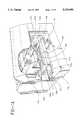
- FIG. 1is a perspective view of an apparatus for assaying biological specimens embodying the present invention
- FIG. 1Ais a perspective view, having portions broken away, of an automatic optical input subsystem of the apparatus for assaying biological specimens shown in FIG. 1;
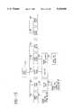
- FIG. 2is a block diagram of the apparatus shown in FIG. 1;
- FIG. 3shows a slide holder and associated control equipment of the apparatus shown in FIG. 1;
- FIG. 4is a block diagram view of focus and light control portions of the apparatus shown in FIG. 1;
- FIG. 5is a plan view of a tissue section microscope slide for use with the apparatus of FIG. 1;
- FIG. 6is a graphical representation of the optical properties employed in biological specimen assay
- FIGS. 7 and 8are schematic views of the biological specimen preparation prior to assay
- FIGS. 9 and 10are flow diagrams of the control procedures invoked in the assay of a plurality of biological specimens
- FIG. 11represents an image field of an optically unfiltered tissue section
- FIG. 12represents the image field of FIG. 11 when optically filtered by a red filter having a passband centered about 620 nanometers;
- FIG. 13represents the image field of FIG. 11 when optically filtered by a green filter having a passband centered about 500 nanometers;
- FIG. 14ais a template for use in identifying slide action points
- FIG. 14bis a representation of a slide tray in which the template of FIG. 14a is visible;
- FIG. 15shows the apparatus operations available from a tray setup function of the apparatus
- FIG. 16is a visual image presented to an operator during the tray setup functions
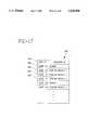
- FIG. 17shows a data file established during tray setup
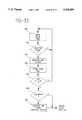
- FIG. 18is a flow diagram of a setup scan routine
- FIG. 19shows a monitor screen displayed during tray setup
- FIG. 20shows a monitor screen displayed during a setup scan routine
- FIG. 21is a flow diagram of analysis by the apparatus after slide locations have been selected.
- FIG. 22is a flow diagram of operations performed to resolve joystick actions.
- FIG. 23is a flow diagram of a scan routine.
- the preferred embodiment disclosed hereinis used for the assay or quantitation of biological specimens specifically estrogen and progesterone in tissue samples.
- the tissue sample staining and measuring techniques for the estrogen/progesterone assayare described in detail in U.S. Pat. No. 5,008,185, issued Apr. 16, 1991 to Bacus which is hereby incorporated by reference.
- the tissue sample assayis performed using a two-color optical system to enhance the optical characteristics of stained tissue samples. It will be apparent to those skilled in the art that many inventive features of the disclosed embodiment may be employed for other types of cell analysis e.g., DNA quantification and that other types of optical apparatus e.g., single color could be employed.
- FIG. 1An apparatus for assaying biological specimens, and embodying the present invention and generally identified by numeral 10 is shown in perspective view in FIG. 1 and in block diagram form in FIG. 2.
- the apparatus 10comprises an interactive optical input system 11a primarily for use in low power scanning of microscope slides of biological specimens to select fields for later analysis.
- An automated assay processing system 11balso comprises a portion of the apparatus for scanning up to eight slides at once at relatively high magnification for performing biological assays on the slide.
- a processor system 32receives signals from the optical units for later image processing.
- the interactive optical system 11acomprises an optical microscope 12, which may be of any conventional type, but in this embodiment, is a Riechart Diastar.
- An optical conversion module 14is mounted on the microscope 12 to enhance the optically magnified image of cell samples viewed with the microscope 12.
- the optical conversion module 14, as may best be seen in FIG. 2,includes a beam-splitting prism 80 which conveys approximately 90% of the light into optical conversion module 14 and passes the remaining 10% to a microscope eyepiece 76.
- the light transmitted into module 14is fed to a dichroic beam-splitter 82 which reflects a portion of the light to a television camera 20 via a red filter 18 and a mirror 81.
- the remaining portion of the lightis filtered by a dichroic beam-splitter 82 and fed to a television camera 26 through a green filter 24.
- the dichroic beam-splitter 82selectively passes light having wavelengths greater than approximately 560 nanometers to the filter 18 and having a wavelength of less than 560 nanometers to the filter 24.
- the dichroic beam-splitter 82acts as a first color filter before the light reaches the color filters 18 and 24.
- Red filter 18is a 620 ⁇ 20 nanometer bandpass optical transmission filter which provides a high contrast image to the camera 20.
- the camera 20then generates an NTSC image signal which is fed through an optical signal switch 90a to an image processor 90 of an image processor module 28 (FIG.
- Green filter 24is a 500 ⁇ 20 nanometer narrow bandpass optical transmission filter which provides a high contrast image to a camera 26.
- the camera 26then feeds an NTSC image signal through the optical signal switch 90a to an image processor 92.
- Both of the image processors 90 and 92contain analog to digital converters for converting the analog NTSC signals to a digitized 384 by 485 array pixel image.
- the center 256 by 256 array of pixels from this digitized imageis then stored within frame buffers internal to the image processors 90 and 92.
- the visual image represented by the 256 by 256 array of pixelsis referred to as an image field.
- the optical elements of conversion module 14are adjusted so that each camera 20 and 26 receives the same optical image and each pixel of the digitized pixel arrays produced by processors 90 and 92, presents the same region of a viewed optical field.
- Each of the image processors 90 and 92is a Model AT428 from the Data Cube Corporation, and includes six internal frame buffers.
- the image processors 90 and 92are connected to a system bus 34 of a computer 32.
- the frame buffers of image processors 90 and 92are mapped into the address space of a microprocessor 36 in computer 32 to provide easy access for image processing.
- an image monitor 30is connected to image processor 92 and displays a cell sample image field stored in a predetermined one of the frame buffers. The storage of an image field representation into the predetermined frame buffer is described later herein.
- the automatic optical conversion module 11bincludes a prism 80a which conveys the light into optical conversion module 14a.
- the light transmitted into module 14ais fed to a dichroic beam-splitter 82a which reflects a portion of the light to a television camera 20a via a red filter 18a and a mirror 81a .
- the remaining portion of the lightis filtered by a dichroic beam-splitter 82a and fed to a television camera 26a through a green filter 24a.
- the dichroic beam-splitter 82aselectively passes light having wavelengths greater than approximately 560 nanometers to the filter 18a and having a wavelength of less than 560 nanometers to the filter 24a.
- the dichroic beam-splitter 82aacts as a first color filter before the light reaches the color filters 18a and 24a.
- Red filter 18ais a 620 ⁇ 20 nanometer bandpass optical transmission filter which provides a high contrast image to the camera 20a.
- the camera 20athen generates an NTSC image signal which is fed through the optical signal switch 90 to the image processor 90 of the image processor module 28 (FIG. 2).
- Green filter 24ais a 500 ⁇ 20 nanometer narrow bandpass optical transmission filter which provides a high contrast image to a camera 26a.
- the camera 26athen feeds an NTSC image signal through the optical signal switch 90a to the image processor 92.
- the microprocessor 36 of computer 32is an Intel 80486 microprocessor which is connected to the system bus 34.
- the optical switch 90aunder control of the microprocessor 36, selects the signal from interactive unit 11a or automatic unit 11b to be fed to the image processors 90 and 92.
- a random access memory 38 and a read only memory 40are also connected to the system bus 34 for storage of program and data.
- a disk controller 42is connected by a local bus 44 to a Winchester disk drive 46 and to a floppy disk drive 48 for secondary information storage.
- local bus 44is connected to a moveable media bulk data drive 45 such as an optical write once read many times (WORM) drive for image field recording and retrieval.
- WORMoptical write once read many times
- a video conversion board 50in this embodiment a VGA board, is connected to the system bus 34 to control an instruction monitor 52 connected to the VGA board 50. Operational information such as selection menus and reports of analysis are displayed on instruction monitor 52.
- a keyboard processor 54is connected to the system bus 34 to interpret signals from a keyboard 56 connected to the keyboard processor 54. Input signals to microprocessor 36 are also generated by a hand control drive (mouse) 13 having a control button 15. Signals from mouse 13 and its button 15 are conveyed to bus 34 via a mouse interface 17.
- a printer 58is connected to the system bus 34 for communication with microprocessor 36.
- the apparatus 10also includes a joystick control device 13a of a type well known in the art. Signals from the joystick 13a are conveyed to bus 34 via a joystick interface 17a.
- the automated image input subsystem 11b of apparatus 10performs automated X-Y slide positioning, image focusing, light intensity adjustment and light color balancing functions.
- the X-Y slide position controlling apparatusis shown in FIGS. 1, 1A, 3 and 4, and includes a slide holder 62a capable of holding eight microscope slides 101 through 108 in side-by-side relationship such that the upper surfaces of the slides are substantially coplanar.
- Slide holder 62awhich is sometimes referred to as a flat bed carrier, is movably attached to the stage 65a of microscope objective 64a by means of a slide holder base 63a.
- the portion of slide holder 62a positionable with respect to microscope objective 64ais controlled by an X position stepper motor 110 and a Y position stepper motor 111 which are mechanically attached to base 63a.
- the stepper motors 110 and 111are of the type known in the art which respond to pulse signals from a slide holder position controller 60.
- the actual X and Y positions of the slide holder 62aare sensed by an X position sensor 68 and a Y position sensor 66, respectively, which substantially continuously report position information to slide holder controller 60.
- the slide holder 62a, base 63a, and position sensors 66 and 68 including limit switches and numbered 110 and 111comprise a commercially available unit from Marzhauser Wetzlar GmbH Model EKSB-S4 with Model MCL-3 control units.
- the slide holder base 63ais capable of placing substantially all of each of slides 101 through 108 under the objective 64a.
- Slide holder position controller 60is connected to system bus 34 by means of a communication path 61.
- Microprocessor 36transmits commands to slide holder position controller 60 specifying an X and Y position to place under the microscope objective 64a.
- Slide holder position controller 60responds to such commands by transmitting to the X and Y stepper motors 110 and 111 the appropriate sets of pulse signals to move the slide holder 62a to the desired X-Y position.
- the actual position of slide holder 62ais checked by slide holder position controller 60 during and at the completion of movement.
- the slide holder position controller 60also maintains an internal record of the X and Y position of the slide holder 62a which internal record can be read by microprocessor 36 via bus 34 and communication path 61.
- the apparatus 10also includes a focus and light controller 73 which controls the light intensity and color balance from the light source 84a, as well as the focus of the image field presented to microscope 12.
- Microprocessor 36communicates with focus and light controller 73, via the system bus 34 and a communication path 74, to control the focus and light properties.
- FIG. 4is a functional block diagram of focus and light controller 73 and its connection to objective 64a and to bus 34.
- the objective 64aincludes a focus stepper motor 75a, which is controlled by focus and light controller 73 through the stepper motor controller 73a to raise and lower the stage 62a, and thereby raise and lower the microscope slides 101 through 108 carried by slide holder 62a.
- Microprocessor 36includes a focus routine which is periodically performed during tissue analysis.
- microprocessor 36reviews a digital representation of an image field from the image processors 90 and 92, and issues a command to focus and light controller 73, to raise or lower the stage by a specified amount. Focus and light controller 73 responsively transmits to focus stepper motor 75a electrical signals to implement the requested stage movement. By continued checking of the quality of the image field and adjustment of the up and down position of the slide holder 62a, microprocessor 36 brings the upper surface of the slide under the objective 64a into focus.
- Microprocessor 36also stores a target value for the light intensity which is to be maintained during tissue sample analysis. This stored light intensity value is used by microprocessor 36 in conjunction with an intensity function to regulate the intensity of light from light source 84a.
- the intensity function of microprocessor 36is enabled, the light intensity as represented by image fields from image processors 90 and 92 is determined. Any departure from the stored target light intensity value is corrected by sending intensity control commands to focus and light controller 73 which responds thereto by controlling a voltage regulator to increase or decrease the voltage applied to light source 84a.
- Voltage regulator 83may be, for example, a standard rotatable voltage regulator which is rotated by a stepper motor operating under the control of electrical signals from focus and light controller 73.
- the analysis performed in the present embodimentrelies on a two-color system. For accuracy of measurement, it is important that the two-colors observed by cameras 20 and 26 be of substantially the same intensity.
- the microprocessor 36includes a color balance function, which is called to match the intensities of the red and green colors applied to cameras 20 and 26 by light source 84.
- Objective 64ahas associated with it a condenser 85a, which is controlled by a stepper motor 86a, electrically connected to focus and light controller 73.
- microprocessorsenses color imbalance by comparing the image field of image processor 90 with that of image processor 92.
- Microprocessor 36sends color balance adjustment commands to focus and light controller 73 in response to color imbalance and through a process of repeated comparison and color balance adjustment commands achieves a color balance suitable for tissue sample analysis.
- FIG. 5shows a representation slide e.g., 102 which has been prepared for analysis in accordance with the embodiment.
- the slide 102includes a dark line outline 87 of a rectangle near one end thereof.
- the rectangle 87which is printed in substantially the same position on all slides is used during focus and light adjustment routines and during slide preparation to identify the placement of tissue samples.
- a method of quantitating nuclear proteins of the present embodimentincludes providing specimen 88 cell objects on slide 102 and staining them with an optical enhancement factor which specifically binds to the nuclear protein.
- the stainis then viewed with the image analysis system 10 to measure the optical density of the stain for intensity measurement and to locate the areas in which stain is found for distribution measurement. Because the intensity of the staining relates to the quantity of the nuclear proteins, measurement of the different optical densities of the stain permits a direct measurement of the quantity of the proteins.
- control cell objects 89are placed on a reference section of the slide 102 to provide a normalization or reference optical density for the staining. Further, one or several counterstains can be used to further distinguish among several features of the cell objects.
- the slideshould be prepared such that the control cell objects 89 overlap the longitudinal center line of the slide (denoted by a dotted line 91 in FIG. 5) and that the control cell objects 89 are closer to the rectangle 87 than is the specimen 88.
- the specimen 88should be positioned overlapping the longitudinal center line and farther from rectangle 87 than the control cell objects 89.
- the staining methodemploys a sensitive peroxidase-antiperoxidase technique for visualization of estrogen or progesterone receptors in specimens through the use of monoclonal antibodies directed specifically against those receptors.
- a diagrammatic representation of the process on the microscopic levelis illustrated in FIGS. 7 and 8. Two portions of a human tumor specimen containing a cell population from which the estrogen receptors are to be measured are placed on the two separate sections of the slide 14 and suitably fixed thereto as by tissue adhesive. The separate sections are then fixed in separate washes of formalin, methanol and acetone, and thereafter, treated with a blocking reagent to prevent non-specific binding of the subsequent reagents.
- the part of the specimen cells 88 to be measuredis incubated with a primary antibody, a monoclonal antibody (rat) to human estrogen receptor in the specimen portion of the slide.
- This antibodyas represented at 128, binds specifically to the estrogen receptor sites ER of this tissue portion.
- the reference portion 89 of the specimenis incubated with a control, normal rat IgG, represented at 130.
- the purpose of the control 130is to evaluate the amount of binding of the immunoperoxidase reagents in this technique to nonspecific sites NS of the specimen to yield a background measurement.
- tissue sections 88 and 89 on the slide 102are then incubated with a bridging antibody, an anti-rat immunoglobulin (goat) illustrated at 132 in both figures.
- the bridging antibody 132binds to the rat antibody 128 against human estrogen receptor in the specimen section 88 and to any bound normal rat IgG 130 in the control section 89.
- a rat PAP complex 134is added to both sections 88 and 89 of the specimen and binds to the anti-rat IgG bridging antibody at 132.
- a solution containing hydrogen peroxide and diaminobenzidine (DAB) and 4 N HClis added to the specimen and control sections.
- DABdiaminobenzidine
- the reaction of the peroxidase with hydrogen peroxideconverts the bound DAB present into an insoluble reddish brown precipitate.
- the proportion of the precipitate and its locationare influenced by the binding positions of the PAP complex and, through the bridging and primary antibodies, the locations and amounts of the estrogen receptors in the specimen.
- the concentrations, timing, and chemical compositions of the reagents used in this staining methodare more fully described in the aforementioned U.S. Pat. No. 5,008,185.
- the monoclonal antibody which is used to bind to the estrogen receptor sitesis one of those developed at the University of Chicago and designated H222 sP2 and H226 sP2, and that which is used to bind to the progesterone receptor is one which is commercially available from Transbio Sarl 6 Rue Thiers, Paris France and designated mPRI.
- the DAB precipitateis then visualized by image analysis with apparatus 10 to determine the quantitation of the estrogen receptors in the specimen.
- the brown precipitatedoes not transmit light well and will show up as dark areas in the cells of the specimen.
- the optical density and hence pixel intensitywill be related directly to the amount of DAB precipitate and to the quantity of estrogen receptor which has bound the antibodies.
- a counterstain of methyl greenis added. It is important to note that both the primary stain of DAB precipitate and the counterstain of methyl green are specific to the nucleus of each cell. This means that debris and other cellular features will appear lighter in the microscope image and can be distinguished.
- a dual camera methodis thereafter applied to distinguish the areas stained by the DAB and the areas stained by the methyl green.
- the red and green filters 18 and 24respectively form monochromatic images of the cell objects at their respective cameras 20 and 26 which images can be stored in the apparatus 10. These images, one by the red filter and the other by the green filter, are used to separate the primary stained areas from the nuclear areas, and to separate the nuclear areas from other cell or field features.
- the results and desirability of this dual filtering of a counterstained cell imageare more fully illustrated in FIG. 6.
- the percentage of light transmitted through the nuclei stained with methyl greenis shown in the curve A as a function of the wavelength of light.
- the percentage of transmission of light for diaminobenzidine (DAB)is shown in curve B as a function of the wavelength of light.
- the bandwidth of wavelengths of light passed by the green filteris illustrated in band C while the bandwidth of wavelengths of light passed by the red filter is illustrated in band D.
- the methyl green stained areais enhanced during one filtering relative to other areas of the cell, and the areas which have diaminobenzidine precipitate are enhanced relative to the methyl green areas during the other filtering.
- the nuclear areas of the cell objectsare optically enhanced along with the areas having DAB precipitate.
- FIG. 11represents an optical image field of a tissue sample as presented to the microscope objective 64.
- objects 200, 202 and 204are green cell nuclei where nuclei 202 and 204 have brown areas 206 and 208 respectively of DAB precipitate.
- Nucleus 200does not contain any estrogen receptor and therefore, does not have any DAB precipitate.
- Objects 210, 212 and 214are various other cell features or debris from the tissue section.
- FIG. 12represents the image field presented by red filter 18 to camera 20 and its associated image processor 90. In FIG. 12, the nuclei 200, 202 and 204 stand out because of the counter staining and filtering, while the DAB areas are not visible.
- FIG. 12represents the image field presented by red filter 18 to camera 20 and its associated image processor 90. In FIG. 12, the nuclei 200, 202 and 204 stand out because of the counter staining and filtering, while the DAB areas are not visible.
- FIG. 12represents the image field presented by red filter 18 to camera 20 and its associated image processor
- FIG. 13represents the image field presented by green filter 24, to camera 26 and its associated image processor 92.
- the estrogen receptor areas 206 and 208stand out so that their area and density can be readily measured.
- the dotted lines of FIG. 13represent the boundaries of nuclei 200, 202 and 204, which are shown for reference purposes.
- a monitor 30is available for displaying image fields of the cell sample.
- microprocessor 36computes a composite image by summing the image field of image processor 90 (of the type shown in FIG. 12). With the image field of image processor 92 (of the type shown in FIG. 13), the composite image is then stored by microprocessor 36 in the predetermined frame buffer of image processor 92 which is the source of images for monitor 30.
- up to eight slides mounted in a slide trayare analyzed in an automatic analysis session.
- One of the eight slides (101)is a calibrate slide and the remaining seven slides are preferably prepared using tissue sections from the same tissue mass.
- the calibrate slide 101is prepared in the same manner as all other slides, but the tissue sections used are taken from a standard tissue mass having known amounts of estrogen and progesterone receptors.
- all eight slides which are to be analyzed in the same sessionare fixed and stained in accordance with the above disclosed process as a batch, so that they all undergo substantially the same preparation.
- slide holder 62awhich secures each slide at a predetermined position on the slide holder.
- calibration slide 101is placed in the left most position and the slides 102 through 108 are distributed in any order in the remaining seven slide positions. All slides are oriented so that their printed rectangle 87 is at the bottom as shown in FIG. 3.
- the slide holderis then inserted into the slide holder base 63a with the printed rectangles away from microscope 12. After placement of the slide holder, the operator signals, by means of keyboard 56, that the analysis is to begin.
- FIGS. 9 and 10A flow diagram of the automated analysis routine is shown in inter-related FIGS. 9 and 10.
- the routinebegins at a step 136 with a request by the apparatus on instruction monitor 52 for patient labelling information.
- patient labellingis completed by means of operator interaction with the keyboard 56, the automated portion of the analysis procedure begins and the operator is free to go about other tasks.
- microprocessor 36by means of control signals sent over system bus 34 to the slide holder position controller 60, requests the movement of slide holder 62a to its maximum X and Y positions, as represented by a point 120 in the upper left of slide 101 and a point 121 in the lower right of slide 108. No actual marks appear on the slides to represent points 120 and 121, but these points are located by the maximum travel of the slide holder 62a.
- the X and Y values of points 120 and 121are read from position sensors 110 and 111 so that the position ranges of slide holder 62a are known by microprocessor 36.
- microprocessor 36can easily compute the X address of the longitudinal center of each slide 101 through 108, and since the position of the rectangle 87 on each slide is also known the Y position of each rectangle 87 can be computed with reasonable accuracy. These slide reference positions are calculated in step 140.
- the analysis routinenext proceeds to step 142 in which the microprocessor 36 requests movement of the slide holder 62 to position the near center of rectangle 87 of slide 101 under the objective 64a.
- the automated analysis routine of the present embodimentis performed using a single 40 ⁇ objective which has a short depth of field on the order of a few microns.
- the slide holder and slidesare relatively precise, they do not necessarily guarantee that the surface of the slides will always be at optimum focus when presented to the microscope objective 64a. Accordingly, as the analysis for each new slide begins, the apparatus is first focused using a line 79 of the slide rectangle 87. After the initial focus on line 79 is achieved, the apparatus is periodically refocused during analysis to provide accurate image fields.
- a step 144the slide 101 is moved so that the path of the objective travels along the imaginary center line 91 (FIG. 5) until line 79 is detected.
- Line 79is of sufficient width and opacity that it is detectable even with a poorly focused objective.
- microprocessor 36monitors the pixel array of image processor 90 which represents the current image field presented to the objective. Microprocessor stops slide movement, when line 79 appears in the image field of image processor 90 and performs a focus routine on the inner edge of line 79.
- microprocessor 36successively analyses the sharpness of the image field from image processor 40 and adjusts the microscope stage to objective distance by means of focus and light controller 73.
- the flowproceeds to block 126 in which the slide is moved back to a point within rectangle 87.
- the rectangle 87is to be free from any tissue section or other contaminants. Accordingly, the light level and color balance can be adjusted by means described above while the presented image field is from within rectangle 87.
- step 150the slide is moved to view successive image fields along the center line 91 in search of a first image field representing reference tissue sample 89.
- the slideis moved so that the objective 64a traces a path represented by a search path line 94 shown in FIG. 5.
- Periodically slide motionis stopped, the objective 64a is focused by the microprocessor 36 and the then current image field from image processor 90 is analyzed to determine if the control sample has been found.
- An image field of control sample 89will be identified in a step 152 as an image field possessing analysis value.
- An image fieldis determined in step 152 to possess analysis value when the area of the nuclear material in the image field from image processor 90 exceeds a predetermined threshold stored in microprocessor 36.
- Microprocessor 36analyzes each image field pixel array from image processor 90 which arrays represent the nuclear image of the image fields. When the nuclear area of an image field exceeds the threshold stored in microprocessor 36, the image field has analysis value and the flow proceeds to step 154 where attributes of the image field are measured and recorded.
- step 154the digitized image field from image processor 90 is analyzed to identify a nuclear boundary level value for the nuclear material in the field.
- the nuclear boundary level which will be used in quantitation of the specimen 88is stored in memory 38.
- microprocessor 36measures the digitized image field from image processor 92 to identify an antibody stain threshold. This threshold is necessary to determine the contribution of the non-specific staining of the control cells and the contribution of the counterstain methyl green, to the total stain detected by the instrument. This antibody stain threshold permits the discrimination between antibody negative stain cells and antibody positive stain cells. After its determination, the antibody stain threshold level is stored in memory 38.
- a step 156is performed in which the digital image fields of both image processors 90 and 92 are stored in memory.
- the digital image fieldsmay advantageously be stored in bulk data drive 45.
- the search path 93begins within rectangle 87 and proceeds along center line 91 until a first image field having analysis value is detected at point 93.
- the search movement patterndirected by microprocessor 36, changes the search movement pattern for image fields, as directed by microprocessor 36, follows a sweeping pattern back and forth across the control as represented in FIG. 5 by the line 94. While traversing the reference specimen 89 successive image fields of the specimen are analyzed and for each image field the possessing analysis value, the nuclear boundary level and the antibody stain threshold are updated. Also, both digital images of each image field found to possess analysis value are stored in memory.
- Image fieldscontinue to be analyzed from control specimen 89 until the total nuclear area of the image fields of analysis value exceeds 5,000 square microns.
- slide holder movementis directed to return the objective 64 to center line 91 and to proceed downwardly (step 160) until a first specimen image field is detected at point 96 of FIG. 5.
- the image field having analysis valueis identified in step 164 of the flow diagram (FIG. 10) based on the nuclear area contained by the image field.
- step 164finds an image field having analysis value
- the flowproceeds to step 166 where attributes of the specimen image field are measured and recorded.
- the attributes measured and recorded in step 166comprise the optical density of DAB areas 206 and 208, the visible area of DAB areas 206 and 208 and a comparison of the total nuclear area in the image field with the area of DAB areas 206 and 208.
- the digitized representations of the image fieldare also stored in memory.
- the entirety of the specimen 88is scanned by the apparatus as represented by the line 94 (FIG. 5). The completion of scanning for tissue sample 88 is detected in step 170.
- the recorded datarelates to calibration slide 101, as is detected in step 171, calibration values are calculated and stored for later use in the analysis of measured attributes of other slides 102 through 108.
- the flowproceeds to a step 172 to determine if all slides have been analyzed in step 172. Since in the present example, they have not, the slide holder is moved to position the objective in the rectangle 87 of the next slide in the slide set, which is slide 102.
- slides 102 through 108will be analyzed in sequence in the same manner as calibrate slide 101, except that the data measured in their specimen portions 88 is not stored as calibrate data but as analysis results.
- the cell sampleswere automatically located by the apparatus during an analysis operation.
- the apparatus 10can be used to preselect points on the slide where analysis is to occur.
- the apparatus 10includes the interactive optical means 11a which comprises the microscope 12 having multiple turret objectives including a low power objective.
- the microscope 12has mounted thereon a manually operable stage for carrying a microscope slide having a biological specimen thereon.
- the manually operable stagemay be manipulated by the operator to bring various portions of the slide under the low power microscope objective.
- the position sensors 12awhich are disclosed in U.S. Pat. No.
- 5,018,209 to Bacusmay be marked by a press of a button 15 on the mouse, keyboard or the like to signal the processor means that the coordinates of that field are to be stored so that the field may later be examined at high power by the automatic optical means 11b.
- the slidemay be quickly and rapidly scanned manually at low power selecting the portions of interest and then loaded into the slide rack 62a with other slides for examination at high power by objective 64a using the high speed automatic processing as set forth previously.
- the low magnification scan of interactive system 11 aallows empty fields and fields which are not of interest to be avoided to reduce the amount of time consumed by the automatic optical means 11b.
- the system 10therefore provides the advantage of the combination of interactive, rapid, low power scanning and storage of coordinates with high power automatic assay for full diagnostic treatment of the biological specimen.
- the imagesmay be called up from the WORM drive 45 for additional editing or for deletion from assays, statistics and the like.
- the systemallows pre-assay editing of the fields by the use of the low power microscope and post-assay editing of the fields with re-assaying by calling up the images from the WORM drive 45.
- the tray of slides 62acould be placed in the automatic optical apparatus 116 and the individual slides, e.g., 101, would be searched for calibrate and specimen samples, which samples would be appropriately analyzed. Additionally, the slides could be previewed under a low power microscope 12 and locations of analysis interest entered directly into the analysis apparatus 10 to identify the starting points of analysis functions.
- a third method and apparatuscan also be employed to identify search locations on microscope slides.
- the third method and apparatuswhich is described in detail below, permits the selection of a plurality of search locations, called action points, on each of the plurality of slides in a slide tray, e.g., 62a, and permits the operator to specify an action e.g., scan or set light, at each selected action point.
- the action points and associated actionsare easily selected interactively with the analysis apparatus 10 in preparation for an analysis session.
- the action points and associated actionscan be selected on other ancillary apparatus and a data file representing such selections can be prepared.
- the slide trayis loaded into the automatic optical apparatus 11b and a corresponding data file is entered into the analysis apparatus 10 by moveable storage means (diskette) or electronic communication.
- the selection of action pointsbegins after at least one slide is mounted in a slide carrier (slide tray) 62a and involves visual inspection of the slides by an operator and entry of information by that operator into the computer 32 by means of keyboard 56 and mouse 13.
- a slide carrierspace tray
- FIG. 14ashows a coordinate grid-forming template 251 as shown in FIG. 14a and a tray setup function 250 (FIG. 15) is initiated on the analysis apparatus 10.
- FIG. 14bshows a slide tray 62a held so that the coordinate grid of the template 251 is formed on the slides.
- the template 251 and slide tray 62amay be held in position by an appropriate jig (not shown).
- the slide tray 62ais positioned over the gridded template which is viewed through the slides.
- Other methods of forming a grid reference on the slidescould be used, such as projecting the grid on the slides by optic means or viewing the slides through a clear gridded template.
- the tray setup functionincludes operator reviewing of its actual slides 101 through 108, a determination of the locations of points of interest (action points) on the slides from the coordinate pattern and the entry into apparatus 10 of information defining the points of interest.
- the tray setup function 250begins with a visual image 270 (FIG. 16) of a slide tray and slides 273 being displayed on instruction monitor 52. Also displayed on monitor 52 in the tray setup step function 250 is a tray setup menu 272, which identifies routines to be performed.
- the individual routines of menu 272are selected by moving a cursor 271 by means of mouse 13 and selecting a routine by pressing the button 15 when the cursor is on a routine.
- the selection of menu items by means of a mouse and cursoris well known in the art.
- the routines available in the tray setup function 250are also shown in flow diagram form in FIG. 15.
- the label tray routine 252is entered to establish the identity of the slide tray being set up for analysis.
- the instruction monitordisplays a window shown at 253 of FIG. 15, requesting entry by the operator of a preassigned tray identity number and a pre-assigned operator number.
- the routineUpon exiting from the label tray routine by operator selection, the routine returns to the tray setup function 250 and establishes a tray data file 280 (FIG. 17) for the identified tray.
- the data file 280is stored in RAM 38 at a location identified by the tray identity number.
- the tray data file 280includes a tray header 281 which stores both the tray identity number and the operator identity number as entered by the operator.
- the operatorselects the label slide routine 255.
- the operatorselects from the displayed slide tray one of the slide images 273 which corresponds to an actual slide in the slide tray being set up.
- the slide image 273is selected by the mouse 13 and cursor 271.
- a promptappears on monitor 52 for operator entry of the type of slide being set up, the patient number for the slide and the accession number.
- the promptis represented at step 257 in FIG. 15.
- the slide typesare shown at 274 in FIG. 16.
- the routinereturns to the tray setup function 250 which stores the entered data in a slide header 282 of data structure 280 (FIG. 17).
- the label slide routine 255can be used to identify all 8 slides in the tray which resulting in the storage of 8 slide headers, each associated with one slide 101-108.
- the actual slide numbers from slides 101-108have been written in parenthesis on slides 273 to show the correspondence between actual slides and slide images.
- the setup scan routineallows the operator to identify action points on the slides and to define an action to be performed at each identified action point.
- a flow diagram of the setup scan routine 258is shown in FIG. 18.
- the operatorfirst selects a slide image 273 by cursor 271 movement.
- the flowproceeds to a step 301 where the identity of the actual slide 103 corresponding to the selected slide image is read.
- a step 302is performed in which a slide grid 276 (FIG. 19), is displayed on monitor 52.
- Slide grid 276is an enlarged image of the selected slide image and includes a reference grid pattern of four columns labelled A through D and nine rows, labelled 1 through 9.
- the rectangles represented in slide grid 276correspond to the pattern of reference rectangles formed on the actual slides in the slide tray 62a, as shown in FIG. 14b.
- the operatorwants to specify a particular point on the actual slide for analysis or other action, he or she selects the rectangle on slide grid 276 which includes the particular point. Since the grid rectangles on the slide grid 276 correspond to the reference rectangles formed on the slides held in the slide holder (FIG. 14b), the identification of a rectangle of interest on slide grid 276 is a relatively simple task.
- a portion of a cell sampleis present in rectangle B-1 of slide 103. Accordingly, the operator moves cursor 271 to the rectangle B-1 of slide grid 276 on monitor 52 and presses button 15 to select rectangle B-1.
- the rectangle positionis read by the apparatus 10 at step 303 (FIG. 18) and the flow proceeds to a step 304, where a large grid 277 and an action menu 278 are displayed on monitor 2.
- Large grid 277represents the selected rectangle B-1 of slide grid 276, and allows precise positioning of an action point within the selected rectangle.
- the large grid 277is sub-divided into, for example, 100 horizontal (X) by 100 vertical (Y) coordinate positions one of which can be selected by moving the tip of cursor 271 thereto and pressing mouse button 15.
- a dot 279is shown in the lower left-hand quadrant of large grid 277 to represent a selected point in cell sample 263.
- the X, Y coordinate position of point 279 in large grid 277is read by the apparatus in step 305. Since the position of rectangle B-1 on the slide is predetermined and its position of point 279 within rectangle B-1 is now known, the absolute X, Y coordinate of the point on the slide is computed and stored in step 306.
- Each action point selectedis associated with one of the actions listed in menu 278. Accordingly, the operator next moves the cursor to menu 278 to select one of the menu items.
- the selected action which is identified in step 307is used in a manner described below to control apparatus 10 during the analysis of the slides on the slide tray. That is, after all slides have been appropriately "marked” with action points, each associated with an action, the slide tray is mounted in automated assay apparatus 11b as shown in FIGS. 1 and 1a and the apparatus 10 implements the specified actions at the specified action points. It is important to note that the actions do not take place when selected but are recorded in a data file, e.g., 280, for use after the slide tray 62a is placed in assay apparatus 11b.
- a data filee.g., 280
- the show field actionwill cause the apparatus 11b to align the specified action point with objective lens 64a and display a focused image field of the action point on image monitor 30.
- the joystick actionwill cause the apparatus to align the specified action point with the objective lens 64a and to release the control of the alignment between the objective 64a and the microscope slide to the operator, through joystick 13a manipulation.
- the set and check light actionsalso cause the apparatus to properly align the specified action point with the objective lens 64a, at which point light levels can be set or checked respectively, as previously discussed.
- the scan actionwill cause the alignment of the microscope objective 64a and the selected action point on a microscope slide and then begin to measure the attributes of a sample on the microscope slide. In the present embodiment, the scan action requires additional information to define the measurements to be made and how the scan is to be performed. The accumulation of such additional information is described later herein.
- a step 308(FIG. 18) is performed to detect the selection of both an action point and its associated action. Subsequently, a check 309 is made to determine if the selected action is a scan action. Flow proceeds to step 311, when the selected action is not a scan action. In step 311, a dot 279 is displayed on monitor 52 image 270 to indicate the position of the newly selected action point. Next, a step 312 is performed to store in data file 280 the accumulated data, called a position record, identifying the coordinate address of the action point and its associated action. For non-scan actions, the position record comprises data representing the location of the selected action point and the associated action.
- the position recordis stored in association with the slide header, e.g., 282 of the slide identified in step 301.
- data file 280FIG. 17
- the position records 283, 284 and 285 associated with slide 101are shown occupying memory locations subsequent to the slide 101 header 282.
- other forms of associationsuch as linking or address translation tables could be used to associate slide headers with their associated position records.
- multiple position recordscan be associated with the same slide.
- step 313a scan criteria menu 279 (FIG. 20) is displayed on instruction monitor 52.
- the scan criteria menu 279in conjunction with mouse and keyboard manipulation by the operator, defines the parameters of the scan to be performed at a previously selected action point.
- the scan type menu item 286can be selected to set the scan-type to raster (as shown), horizontal or vertical. Raster scanning is a zig-zag pattern, as shown in FIG. 5, horizontal scanning consists of a straight line across the slide and vertical scanning consists of a straight line along the slide length.
- the X and Y step rate menu items 288 and 289can be selected and set to define the spacing between evaluated image fields. Similarly, the definitions of blank fields and good fields (fields of analysis value) can be established by selecting and setting menu items 290 and 291.
- the sample type menu item 293allows the operator to specify whether the sample being evaluated is a specimen or a calibration sample. Specifying the sample type identifies how the measured cell object attributes in the image fields are to be evaluated when the slide is later analyzed in the apparatus 11b.
- the scan criteria menu 279also includes a settable value 295 to identify the end of a scan line. As shown in menu 279, an end of line has been set to occur when three consecutive blank image fields are viewed. Menu 279 also includes a settable value 296 which terminates a raster scan at a preset number of zig-zags and a settable value 297 which terminates a scan when a set number of image fields have been analyzed.
- step 314After the scan criteria have been set using the scan criteria menu 279, the operator exits from the menu and the apparatus reads, at step 314, the established scan criteria values. From step 314, flow proceeds to block 311 where the action points are displayed on the slide tray image 270, as previously described. Flow proceeds through step 312, in which the position record is stored in data file 280, to the select slide step 300. It should be mentioned that for scan actions, the position record stored in data file 280 includes the scan defining criteria established in menu 279 in addition to the action point coordinates and specified action, e.g., scan. At the conclusion of the setup scan routine 258, flow returns to the tray setup function 250 of FIG. 15.
- a load setup routine 259responds to the operator entry (step 260) of a slide tray identity, for which a data file was previously created, by reading (step 261) the identified slide tray data file.
- a save setup routine 262commits a just-prepared data file 280 to a more secure memory storage, for example, into disk storage.
- a clear setup routine 264permits the clearing of the most recently created setup data file before it is committed to the more secure storage.
- a delete setup routine 263enables the deletion of an identified data file from the more secure memory area.
- a slide tray data file 280 as represented in FIG. 17exists in memory.
- the slide tray data file 280is accessible by its tray identity number and includes data representations of one or more action points, each in association with one of the described actions.
- FIG. 21is a flow diagram of the steps performed by apparatus 10 in the analysis of biological specimens mounted on the slides of the identified slide tray.
- the preceding actionsestablish a data file 280 identifying action points and actions for a slide tray identified by an identity number.
- the slide trayis loaded into automated assay processing system 11b of apparatus 10 and the slide tray identity of the loaded slide tray is entered (step 320) at keyboard 56.
- the slide tray rangesare found in step 322 and slide positions calculated in step 324 in the manner described above with regard to the flow diagram of FIG. 9.
- the computer 32retrieves (step 326) the slide tray data file identified by the slide tray identity entered in step 320.
- a step 327is performed in which the position records of all slides are read from the slide tray data file 280 and reviewed to identify all action points associated with joystick actions.
- the joystick actionsare separated from the other actions because they involve continued operator activity.
- FIG. 22is a flow diagram of the joystick completion routine 328.
- the slide trayis moved (step 329) by the automated assay system 11b to align the first joystick action point with the microscope objective 64a.
- the image field at the action pointis presented on display monitor 30 and the X-Y position control of the slide tray 62a is released to the joystick (step 330).
- the computer 32responds to joystick signals by controlling the assay processing system 11b to move the slide to positions determined by operator interaction with the joystick 13a.
- the mouse button 15is pressed. The pressing of button 15 is detected in step 332.
- action step 344the slide headers e.g., 282 (FIG. 17) are reviewed in sequence from slide 101 through slide 108 to identify slides to be analyzed.
- a slide header for a slide to be analyzedis accessed, its associated position records are accessed in sequence to control the operation of the analysis apparatus.
- the objective 64ais substantially aligned with the action point defined in the position record, and the associated action stored in the position record is performed.
- the actionis a show field action 345, the assay processing system 11b is controlled to present the image at the action point to display monitor 30 and to record a copy of the image. After such recording, flow returns to the action step 344 for the analysis of another position record.
- a position recordincludes a set light or check light action
- the set 346 or check light 347 function respectivelyis performed after movement of the apparatus to the action point defined in the position record.
- the remaining action typeis performed through action function 344 is the scan action 348, which is shown in greater detail in FIG. 23.
- the scan actionbegins at step 350, in which the slide tray 62a is controlled to move the image field at the selected action point to microscope objective 64a. As previously discussed, the field is focused after each move operation. The image field at the action point is then analyzed in step 352 to determine whether the image field has analysis value.
- the scan criteria of the present position recordis consulted to determine the definition of a good field. For example, in the scan criteria represented in the menu 279 (FIG. 20) a good field is one in which 70% of its area comprises cell objects.
- the flowreturns to block 350 where the slide tray is moved to place a new image field under objective 64a.
- the type of move operation performedis controlled by the previously established scan type, X step rate and Y step rate stored in the position record type for the present action point. For example, if the scan type is set to vertical scanning and the Y step rate to 2 apparatus 11b would be controlled to move in the Y direction by two fields and stop to image a new field. After the new image field is focused, it is again analyzed in step 352 for a determination of its value for analysis. When the analysis value step 352 determines that the current image field has analysis value, flow proceeds to step 354 where the attributes of the cell objects in the image field are measured and recorded. Next a pixel image of the current image field is stored in bulk data storage in step 356 and a step 358 is performed to determine if the end of the scan has been reached.
- step 360is performed to determine the sample type of the cell objects being analyzed. If the sample type is a calibrate sample, the calibrate values are computed and stored in a step 362 and the flow returns to the action step 344. Alternatively, when step 360 determines that a specimen sample has been scanned, flow returns directly to the action step 344.
- the computer 32again reviews the slide tray data file to identify additional, unserviced position records. Action step 344 will service these unserviced position records until all have been serviced. At which time, a message is displayed on instruction monitor 52 which indicates the completion of the present analysis operation.
- the operatorenters a sample type during the setting of scan criteria (FIG. 20).
- the sample typeis either specimen or calibrate.
- Other choices of sample typecould also be available without departing from the invention.
- the type of assaysuch as DNA mass assay or red blood cell hemoglobin assay, could be set as sample types and the apparatus 10 could analyze the measured and recorded attributes accordingly.
- each slide in a slide traycould include different types of cell samples such as blood cells or tumor cells prepared in a manner specific to that type of cell sample. In such situations, the operator would enter the cell type during the label slide routine 255.
- the analysis apparatuswould then read the sample type from the slide header, e.g., 282 to cause the appropriate analysis routines to be executed.
- an action point pre-selection embodimentincludes the ability to specify and record an action to be performed at each action point. Certain actions have been specifically disclosed, however, persons of ordinary skill in the art may include other actions without departing from the invention. Additionally, the disclosed embodiments use display monitors and menus for data entry. Other types of data entry could be used without departing from the invention.
Landscapes
- Physics & Mathematics (AREA)
- Analytical Chemistry (AREA)
- General Physics & Mathematics (AREA)
- Chemical & Material Sciences (AREA)
- Immunology (AREA)
- Biochemistry (AREA)
- General Health & Medical Sciences (AREA)
- Life Sciences & Earth Sciences (AREA)
- Health & Medical Sciences (AREA)
- Pathology (AREA)
- Engineering & Computer Science (AREA)
- Quality & Reliability (AREA)
- Optics & Photonics (AREA)
- Investigating Or Analysing Biological Materials (AREA)
- Investigating Or Analysing Materials By Optical Means (AREA)
- Microscoopes, Condenser (AREA)
- Sampling And Sample Adjustment (AREA)
Abstract
Description
Claims (38)
Priority Applications (5)
| Application Number | Priority Date | Filing Date | Title |
|---|---|---|---|
| US07/837,051US5428690A (en) | 1991-09-23 | 1992-02-18 | Method and apparatus for automated assay of biological specimens |
| CA002089518ACA2089518A1 (en) | 1992-02-18 | 1993-02-15 | Method and apparatus for automated assay of biological specimens |
| EP97108890AEP0798550A1 (en) | 1992-02-18 | 1993-02-17 | Microscope slide viewing apparatus |
| EP19930102433EP0557871A3 (en) | 1992-02-18 | 1993-02-17 | Method and apparatus for automated assay of biological specimens |
| JP5029263AJPH06281553A (en) | 1992-02-18 | 1993-02-18 | Method and equipment for automated calibration of biological specimen |
Applications Claiming Priority (2)
| Application Number | Priority Date | Filing Date | Title |
|---|---|---|---|
| US76433691A | 1991-09-23 | 1991-09-23 | |
| US07/837,051US5428690A (en) | 1991-09-23 | 1992-02-18 | Method and apparatus for automated assay of biological specimens |
Related Parent Applications (1)
| Application Number | Title | Priority Date | Filing Date |
|---|---|---|---|
| US76433691AContinuation-In-Part | 1991-09-23 | 1991-09-23 |
Publications (1)
| Publication Number | Publication Date |
|---|---|
| US5428690Atrue US5428690A (en) | 1995-06-27 |
Family
ID=25273380
Family Applications (1)
| Application Number | Title | Priority Date | Filing Date |
|---|---|---|---|
| US07/837,051Expired - LifetimeUS5428690A (en) | 1991-09-23 | 1992-02-18 | Method and apparatus for automated assay of biological specimens |
Country Status (4)
| Country | Link |
|---|---|
| US (1) | US5428690A (en) |
| EP (2) | EP0798550A1 (en) |
| JP (1) | JPH06281553A (en) |
| CA (1) | CA2089518A1 (en) |
Cited By (146)
| Publication number | Priority date | Publication date | Assignee | Title |
|---|---|---|---|---|
| WO1996007977A1 (en)* | 1994-09-08 | 1996-03-14 | Neopath, Inc. | Cytological system illumination integrity checking apparatus and method |
| WO1996031835A1 (en)* | 1995-04-04 | 1996-10-10 | Base Ten Systems, Inc. | Ultrasonic image archiving method and system |
| US5625706A (en)* | 1995-05-31 | 1997-04-29 | Neopath, Inc. | Method and apparatus for continously monitoring and forecasting slide and specimen preparation for a biological specimen population |
| WO1998003933A1 (en)* | 1996-07-23 | 1998-01-29 | R2 Technology, Inc. | User interface for computer aided diagnosis system |
| US5715327A (en)* | 1994-09-20 | 1998-02-03 | Neopath, Inc. | Method and apparatus for detection of unsuitable conditions for automated cytology scoring |
| US5732150A (en)* | 1995-09-19 | 1998-03-24 | Ihc Health Services, Inc. | Method and system for multiple wavelength microscopy image analysis |
| US5793969A (en)* | 1993-07-09 | 1998-08-11 | Neopath, Inc. | Network review and analysis of computer encoded slides |
| WO1998039728A1 (en)* | 1997-03-03 | 1998-09-11 | Bacus Research Laboratories, Inc. | Method and apparatus for creating a virtual microscope slide |
| US5843644A (en)* | 1994-03-01 | 1998-12-01 | The United States Of America As Represented By The Secretary Of The Department Of Health And Human Services | Isolation of cellular material under microscopic visualization using an adhesive/extraction reagent tipped probe |
| US5843657A (en)* | 1994-03-01 | 1998-12-01 | The United States Of America As Represented By The Department Of Health And Human Services | Isolation of cellular material under microscopic visualization |
| US6007996A (en)* | 1995-12-12 | 1999-12-28 | Applied Spectral Imaging Ltd. | In situ method of analyzing cells |
| WO2000015105A1 (en) | 1998-09-14 | 2000-03-23 | Lucid, Inc. | A system for marking the locations of imaged tissue with respect to the surface of the tissue |
| US6101265A (en)* | 1996-08-23 | 2000-08-08 | Bacus Research Laboratories, Inc. | Method and apparatus for acquiring and reconstructing magnified specimen images from a computer-controlled microscope |
| WO2000062247A1 (en) | 1999-04-13 | 2000-10-19 | Chromavision Medical Systems, Inc. | Histological reconstruction and automated image analysis |
| US6137897A (en)* | 1997-03-28 | 2000-10-24 | Sysmex Corporation | Image filing system |
| WO2001004828A1 (en)* | 1999-07-13 | 2001-01-18 | Chromavision Medical Systems, Inc. | Automated detection of objects in a biological sample |
| US6181811B1 (en) | 1998-01-13 | 2001-01-30 | Neopath, Inc. | Method and apparatus for optimizing biological and cytological specimen screening and diagnosis |
| US6215892B1 (en) | 1995-11-30 | 2001-04-10 | Chromavision Medical Systems, Inc. | Method and apparatus for automated image analysis of biological specimens |
| EP1063974A4 (en)* | 1998-03-07 | 2001-06-13 | Stephen C Wardlaw | Analysis of quiescent anticoagulated whole blood samples |
| US6269846B1 (en) | 1998-01-13 | 2001-08-07 | Genetic Microsystems, Inc. | Depositing fluid specimens on substrates, resulting ordered arrays, techniques for deposition of arrays |
| US6330349B1 (en)* | 1995-11-30 | 2001-12-11 | Chromavision Medical Systems, Inc. | Automated method for image analysis of residual protein |
| US20020001402A1 (en)* | 1999-11-01 | 2002-01-03 | Tel Aviv Medical Center Research Development Fund | System and method for generating a profile of particulate components of a body fluid sample |
| US6349264B1 (en)* | 1996-10-07 | 2002-02-19 | Lab Vision Corporation | Method and apparatus for automatic tissue staining |
| WO2001031566A3 (en)* | 1999-10-29 | 2002-02-21 | Cytyc Corp | Apparatus and methods for verifying the location of areas of interest within a sample in an imaging system |
| US20020025064A1 (en)* | 2000-06-23 | 2002-02-28 | Teruaki Itoh | Specimen processing system |
| US6396941B1 (en) | 1996-08-23 | 2002-05-28 | Bacus Research Laboratories, Inc. | Method and apparatus for internet, intranet, and local viewing of virtual microscope slides |
| US6404906B2 (en) | 1997-03-03 | 2002-06-11 | Bacus Research Laboratories,Inc. | Method and apparatus for acquiring and reconstructing magnified specimen images from a computer-controlled microscope |
| US6407858B1 (en) | 1998-05-14 | 2002-06-18 | Genetic Microsystems, Inc | Focusing of microscopes and reading of microarrays |
| WO2002050759A1 (en)* | 2000-12-19 | 2002-06-27 | Bacus Research Laboratories, Inc. | Method and apparatus for processing an image of a tissue sample microarray |
| US6418236B1 (en)* | 1999-06-24 | 2002-07-09 | Chromavision Medical Systems, Inc. | Histological reconstruction and automated image analysis |
| US20020090120A1 (en)* | 2001-01-11 | 2002-07-11 | Wetzel Arthur W. | System and method for finding regions of interest for microscopic digital montage imaging |
| US20020090122A1 (en)* | 2000-11-03 | 2002-07-11 | Baer Thomas M. | Road map image guide for automated microdissection |
| US20020090127A1 (en)* | 2001-01-11 | 2002-07-11 | Interscope Technologies, Inc. | System for creating microscopic digital montage images |
| US6428752B1 (en) | 1998-05-14 | 2002-08-06 | Affymetrix, Inc. | Cleaning deposit devices that form microarrays and the like |
| WO2002101635A1 (en)* | 2001-06-12 | 2002-12-19 | Applied Imaging Corporation | Automated scanning method for pathology samples |
| US6521463B2 (en)* | 1999-08-20 | 2003-02-18 | Robert A. Levine | Method and assembly for separating formed constituents from a liquid constituent in a complex biologic fluid sample |
| US20030068638A1 (en)* | 2001-08-03 | 2003-04-10 | William Cork | Nanoparticle imaging system and method |
| US20030120633A1 (en)* | 2001-11-13 | 2003-06-26 | Torre-Bueno Jose De La | System for tracking biological samples |
| US20030179445A1 (en)* | 1999-10-29 | 2003-09-25 | Garrick Maenle | Cytological imaging systems and methods |
| US6665060B1 (en) | 1999-10-29 | 2003-12-16 | Cytyc Corporation | Cytological imaging system and method |
| US20030231791A1 (en)* | 2002-06-12 | 2003-12-18 | Torre-Bueno Jose De La | Automated system for combining bright field and fluorescent microscopy |
| US20040004614A1 (en)* | 2002-02-22 | 2004-01-08 | Bacus Laboratories, Inc. | Focusable virtual microscopy apparatus and method |
| US20040008894A1 (en)* | 1998-06-01 | 2004-01-15 | Zeineh Jack A. | Compression packaged image transmission for telemicroscopy |
| US20040033163A1 (en)* | 2001-11-26 | 2004-02-19 | Lab Vision Corporation | Automated tissue staining system and reagent container |
| US20040058401A1 (en)* | 1999-04-13 | 2004-03-25 | Blaise Bossy | Method for detecting rare event |
| US6718053B1 (en)* | 1996-11-27 | 2004-04-06 | Chromavision Medical Systems, Inc. | Method and apparatus for automated image analysis of biological specimens |
| US6722395B2 (en) | 1998-01-13 | 2004-04-20 | James W. Overbeck | Depositing fluid specimens on substrates, resulting ordered arrays, techniques for analysis of deposited arrays |
| US20040081345A1 (en)* | 2002-10-28 | 2004-04-29 | Ventana Medical Systems, Inc. | Color space transformations for use in identifying objects of interest in biological specimens |
| US6735531B2 (en) | 1996-10-07 | 2004-05-11 | Lab Vision Corporation | Method and apparatus for automatic tissue staining |
| US20040101952A1 (en)* | 2002-11-27 | 2004-05-27 | 3M Innovative Properties Company | Loading and ejection systems for biological growth plate scanner |
| US20040102903A1 (en)* | 2002-11-27 | 2004-05-27 | Graessle Josef A. | Biological growth plate scanner |
| US20040101951A1 (en)* | 2002-11-27 | 2004-05-27 | Albert Vent | Mounting platform for biological growth plate scanner |
| US20040101954A1 (en)* | 2002-11-27 | 2004-05-27 | Graessle Josef A. | Back side plate illumination for biological growth plate scanner |
| US6745067B1 (en) | 1998-09-14 | 2004-06-01 | Lucid, Inc. | System for marking the locations of imaged tissue with respect to the surface of the tissue |
| WO2004051554A1 (en)* | 2002-11-27 | 2004-06-17 | 3M Innovative Properties Company | Biological growth plate scanner with automated image processing profile selection |
| US20040121334A1 (en)* | 2002-12-19 | 2004-06-24 | Kimberly-Clark Worldwide, Inc. | Self-calibrated flow-through assay devices |
| US20040146917A1 (en)* | 2001-08-03 | 2004-07-29 | Nanosphere, Inc. | Nanoparticle imaging system and method |
| US20040175760A1 (en)* | 1996-10-09 | 2004-09-09 | Symyx Technologies, Inc. | Analysis of chemical data from images |
| US6792132B1 (en)* | 1998-02-03 | 2004-09-14 | Hakuju Institute For Health Science Co., Ltd. | Inspection method for microorganisms and the like, and unit therefor |
| US6798571B2 (en) | 2001-01-11 | 2004-09-28 | Interscope Technologies, Inc. | System for microscopic digital montage imaging using a pulse light illumination system |
| US6804385B2 (en) | 2000-10-24 | 2004-10-12 | Oncosis | Method and device for selectively targeting cells within a three-dimensional specimen |
| US20040202357A1 (en)* | 2003-04-11 | 2004-10-14 | Perz Cynthia B. | Silhouette image acquisition |
| US6816606B2 (en) | 2001-02-21 | 2004-11-09 | Interscope Technologies, Inc. | Method for maintaining high-quality focus during high-throughput, microscopic digital montage imaging |
| US20050002547A1 (en)* | 2000-04-03 | 2005-01-06 | Torre-Bueno Jose De La | Remote interpretation of medical images |
| US20050037406A1 (en)* | 2002-06-12 | 2005-02-17 | De La Torre-Bueno Jose | Methods and apparatus for analysis of a biological specimen |
| US20050053266A1 (en)* | 2003-09-05 | 2005-03-10 | Plumb Michael R. | Counting biological agents on biological growth plates |
| US20050053265A1 (en)* | 2003-09-04 | 2005-03-10 | 3M Innovative Properties Company | Biological growth plate scanner with automated intake |
| US6867038B2 (en) | 1994-03-01 | 2005-03-15 | The United States Of America As Represented By The Department Of Health And Human Services | Isolation of cellular material under microscopic visualization |
| WO2005036451A1 (en)* | 2003-10-08 | 2005-04-21 | Lifespan Biosciences, Inc. | Automated microspcope slide tissue sample mapping and image acquisition |
| US20050191704A1 (en)* | 2004-03-01 | 2005-09-01 | Kimberly-Clark Worldwide, Inc. | Assay devices utilizing chemichromic dyes |
| US20050202558A1 (en)* | 2004-03-15 | 2005-09-15 | Koller Manfred R. | Methods for purification of cells based on product secretion |
| EP1256087A4 (en)* | 2000-02-01 | 2005-12-21 | Chromavision Med Sys Inc | Method and apparatus for automated image analysis of biological specimens |
| US20050281484A1 (en)* | 2004-06-17 | 2005-12-22 | Perz Cynthia B | System and method of registering field of view |
| US20050285049A1 (en)* | 1998-03-20 | 2005-12-29 | Montagu Jean I | Focusing of microscopes and reading of microarrays |
| US20060002636A1 (en)* | 2004-06-30 | 2006-01-05 | Torre-Bueno Jose D L | Data structure of an image storage and retrieval system |
| US6998270B2 (en) | 2001-11-26 | 2006-02-14 | Lab Vision Corporation | Automated tissue staining system and reagent container |
| US20060034543A1 (en)* | 2004-08-16 | 2006-02-16 | Bacus James V | Method and apparatus of mechanical stage positioning in virtual microscopy image capture |
| US7006674B1 (en) | 1999-10-29 | 2006-02-28 | Cytyc Corporation | Apparatus and methods for verifying the location of areas of interest within a sample in an imaging system |
| US20060050946A1 (en)* | 2002-05-10 | 2006-03-09 | Mitchison Timothy J | Computer-assisted cell analysis |
| US20060154236A1 (en)* | 2004-11-11 | 2006-07-13 | Altschuler Steven J | Computer-assisted analysis |
| US20060180489A1 (en)* | 2005-02-02 | 2006-08-17 | Cytyc Corporation | Slide tray |
| US20060246597A1 (en)* | 2005-04-29 | 2006-11-02 | Kimberly-Clark Worldwide, Inc. | Flow control technique for assay devices |
| US20060246600A1 (en)* | 2005-04-29 | 2006-11-02 | Kimberly-Clark Worldwide, Inc. | Metering technique for lateral flow assay devices |
| US20060276974A1 (en)* | 2003-07-14 | 2006-12-07 | Trestle Acquisition Corp. | System for remote viewing and display of a slide |
| US20060279790A1 (en)* | 2005-06-10 | 2006-12-14 | Fuji Xerox Co., Ltd. | Image processing system |
| US20070020605A1 (en)* | 2005-06-17 | 2007-01-25 | Fei Company | Combined hardware and software instrument simulator for use as a teaching aid |
| US20070031043A1 (en)* | 2005-08-02 | 2007-02-08 | Perz Cynthia B | System for and method of intelligently directed segmentation analysis for automated microscope systems |
| US20070048815A1 (en)* | 2005-08-31 | 2007-03-01 | Kimberly-Clark Worldwide, Inc. | Enzyme detection technique |
| US20070048807A1 (en)* | 2005-08-31 | 2007-03-01 | Kimberly-Clark Worldwide, Inc. | Diagnostic test kits with improved detection accuracy |
| US20070048182A1 (en)* | 2005-08-31 | 2007-03-01 | Kimberly-Clark Worldwide, Inc. | Nitrite detection technique |
| US20070134811A1 (en)* | 2005-12-13 | 2007-06-14 | Kimberly-Clark Worldwide, Inc. | Metering technique for lateral flow assay devices |
| US20070134810A1 (en)* | 2005-12-14 | 2007-06-14 | Kimberly-Clark Worldwide, Inc. | Metering strip and method for lateral flow assay devices |
| US7285424B2 (en) | 2002-08-27 | 2007-10-23 | Kimberly-Clark Worldwide, Inc. | Membrane-based assay devices |
| US20070269875A1 (en)* | 2003-10-31 | 2007-11-22 | Koller Manfred R | Method and apparatus for cell permeabilization |
| US20080020128A1 (en)* | 2006-07-24 | 2008-01-24 | Van Ryper William John | Automated microscope for blood cell analysis |
| US20080057528A1 (en)* | 2006-08-30 | 2008-03-06 | Kimberly-Clark Worldwide, Inc. | Detection of hydrogen peroxide released by enzyme-catalyzed oxidation of an analyte |
| US20080145272A1 (en)* | 2006-12-15 | 2008-06-19 | Feaster Shawn R | Lateral flow assay device |
| US20080145949A1 (en)* | 2006-12-15 | 2008-06-19 | Xuedong Song | Indicator immobilization on assay devices |
| US20080145945A1 (en)* | 2006-12-15 | 2008-06-19 | Xuedong Song | Lateral flow assay device and absorbent article containing same |
| US20080145947A1 (en)* | 2006-12-14 | 2008-06-19 | Kimberly-Clark Worldwide, Inc. | Detection of formaldehyde in urine samples |
| US20080212866A1 (en)* | 2006-12-20 | 2008-09-04 | Ventana Medical Systems, Inc. | Quantitative, multispectral image analysis of tissue specimens stained with quantum dots |
| US20080235233A1 (en)* | 1999-10-22 | 2008-09-25 | Cerner Innovation, Inc. | Genetc profiling and banking system and method |
| US20080240613A1 (en)* | 2007-03-23 | 2008-10-02 | Bioimagene, Inc. | Digital Microscope Slide Scanning System and Methods |
| US7432105B2 (en) | 2002-08-27 | 2008-10-07 | Kimberly-Clark Worldwide, Inc. | Self-calibration system for a magnetic binding assay |
| US7439079B2 (en) | 2005-04-29 | 2008-10-21 | Kimberly-Clark Worldwide, Inc. | Assay devices having detection capabilities within the hook effect region |
| US20090185267A1 (en)* | 2005-09-22 | 2009-07-23 | Nikon Corporation | Microscope and virtual slide forming system |
| US20090296083A1 (en)* | 2006-03-14 | 2009-12-03 | Saaski Elric W | Optical assay apparatus and methods |
| US20100007727A1 (en)* | 2003-04-10 | 2010-01-14 | Torre-Bueno Jose De La | Automated measurement of concentration and/or amount in a biological sample |
| US7651841B2 (en) | 2001-12-24 | 2010-01-26 | Kimberly-Clark Worldwide, Inc. | Polyelectrolytic internal calibration system of a flow-through assay |
| US20100021077A1 (en)* | 2005-09-13 | 2010-01-28 | Roscoe Atkinson | Image quality |
| US7713748B2 (en) | 2003-11-21 | 2010-05-11 | Kimberly-Clark Worldwide, Inc. | Method of reducing the sensitivity of assay devices |
| US20100179310A1 (en)* | 2009-01-09 | 2010-07-15 | Cyntellect, Inc. | Genetic analysis of cells |
| US7781172B2 (en) | 2003-11-21 | 2010-08-24 | Kimberly-Clark Worldwide, Inc. | Method for extending the dynamic detection range of assay devices |
| US20100290948A1 (en)* | 2009-05-15 | 2010-11-18 | Xuedong Song | Absorbent articles capable of indicating the presence of urinary tract infections |
| US7939342B2 (en) | 2005-03-30 | 2011-05-10 | Kimberly-Clark Worldwide, Inc. | Diagnostic test kits employing an internal calibration system |
| US7943395B2 (en) | 2003-11-21 | 2011-05-17 | Kimberly-Clark Worldwide, Inc. | Extension of the dynamic detection range of assay devices |
| US20110153220A1 (en)* | 2008-03-04 | 2011-06-23 | Bolea Phillip A | Processing of biological growth media based on measured manufacturing characteristics |
| US20110158499A1 (en)* | 2008-03-04 | 2011-06-30 | Bolea Phillip A | Information management in automated processing of biological growth media |
| US20110201075A1 (en)* | 1997-03-27 | 2011-08-18 | Cyntellect, Inc. | Optoinjection methods |
| US8401263B2 (en) | 1997-03-27 | 2013-03-19 | Intrexon Corporation | Method and apparatus for selectively targeting specific cells within a cell population |
| EP2642326A3 (en)* | 2012-03-20 | 2013-11-13 | MetaSystems Hard & Software GmbH | Automatic calibration of a microscope scanning system |
| US8645167B2 (en) | 2008-02-29 | 2014-02-04 | Dakocytomation Denmark A/S | Systems and methods for tracking and providing workflow information |
| US8788213B2 (en) | 2009-01-12 | 2014-07-22 | Intrexon Corporation | Laser mediated sectioning and transfer of cell colonies |
| US20140292813A1 (en)* | 2013-04-01 | 2014-10-02 | Canon Kabushiki Kaisha | Image processing apparatus and image processing method |
| WO2014205557A1 (en)* | 2013-06-26 | 2014-12-31 | Huron Technologies International Inc. | Preview station and method for taking preview images of microscope slides |
| US9036255B2 (en) | 2009-10-19 | 2015-05-19 | Ventana Medical Systems, Inc. | Method and device for slide caching |
| US20160004900A1 (en)* | 2014-01-17 | 2016-01-07 | Ffei Limited | Method for forming an image reference device |
| EP1745270B1 (en) | 2004-05-11 | 2016-03-30 | Carl Zeiss Microscopy GmbH | Method for machining a material by using laser irradiation, and control system |
| US9310598B2 (en) | 2009-03-11 | 2016-04-12 | Sakura Finetek U.S.A., Inc. | Autofocus method and autofocus device |
| US20160321495A1 (en)* | 2013-10-07 | 2016-11-03 | Ventana Medical Systems, Inc. | Systems and methods for comprehensive multi-assay tissue analysis |
| WO2018099918A1 (en)* | 2016-11-29 | 2018-06-07 | Koninklijke Philips N.V. | Slide holding in digital pathology |
| US10007102B2 (en) | 2013-12-23 | 2018-06-26 | Sakura Finetek U.S.A., Inc. | Microscope with slide clamping assembly |
| US10129480B2 (en) | 2014-07-09 | 2018-11-13 | Olympus Corporation | Specimen observation device |
| US10139613B2 (en) | 2010-08-20 | 2018-11-27 | Sakura Finetek U.S.A., Inc. | Digital microscope and method of sensing an image of a tissue sample |
| US10156501B2 (en) | 2001-11-05 | 2018-12-18 | Life Technologies Corporation | Automated microdissection instrument for determining a location of a laser beam projection on a worksurface area |
| US10241310B2 (en) | 2012-06-13 | 2019-03-26 | Ffei Limited | Method of forming an imaging calibration device |
| US10269094B2 (en) | 2013-04-19 | 2019-04-23 | Sakura Finetek U.S.A., Inc. | Method for generating a composite image of an object composed of multiple sub-images |
| US10430955B2 (en)* | 2016-08-31 | 2019-10-01 | The Regents Of The University Of California | High content screening workflows for microscope imaging |
| US10433784B2 (en) | 2014-05-05 | 2019-10-08 | Caliber Imaging & Diagnostics, Inc. | System and method for mapping the locations of captured confocal images of a lesion in skin tissue |
| US10866170B2 (en) | 2011-01-24 | 2020-12-15 | Roche Molecular Systems, Inc | Devices, systems, and methods for extracting a material from a material sample |
| US10871425B2 (en) | 2015-01-31 | 2020-12-22 | Roche Molecular Systems Inc. | Systems and methods for meso-dissection |
| US10876933B2 (en) | 2016-11-09 | 2020-12-29 | Ventana Medical Systems, Inc. | Automated tissue dissection instrument and methods of using the same |
| US11125660B2 (en) | 2015-01-31 | 2021-09-21 | Roche Molecular Systems, Inc. | Systems and methods for meso-dissection |
| US11280803B2 (en) | 2016-11-22 | 2022-03-22 | Sakura Finetek U.S.A., Inc. | Slide management system |
| US11459604B2 (en) | 2018-07-12 | 2022-10-04 | Luminex Corporation | Systems and methods for performing variable sample preparation and analysis processes |
| CN118603888A (en)* | 2024-08-07 | 2024-09-06 | 徐州聚之科光电科技有限公司 | A telescope lens image measuring instrument and measuring method thereof |
Families Citing this family (23)
| Publication number | Priority date | Publication date | Assignee | Title |
|---|---|---|---|---|
| ES2048659B1 (en)* | 1992-07-14 | 1996-12-16 | Univ Cordoba | LOGICIAL METHOD FOR ARTIFICIAL VISION IN METALOGRAPHY. |
| CA2132269C (en)* | 1993-10-12 | 2000-02-01 | Rainer Hermann Doerrer | Interactive automated cytology method and system |
| WO1996009602A1 (en)* | 1994-09-20 | 1996-03-28 | Neopath, Inc. | Biological analysis system self-calibration apparatus |
| US5889880A (en)* | 1995-06-07 | 1999-03-30 | Autocyte, Inc. | Interactive automated cytology method incorporating both manual and automatic determinations |
| US5870200A (en)* | 1997-08-29 | 1999-02-09 | Becton Dickinson And Company | Apparatus for determining the thickness of an optical sample |
| US5781303A (en)* | 1997-08-29 | 1998-07-14 | Becton Dickinson And Company | Method for determining the thickness of an optical sample |
| DE19921127A1 (en)* | 1999-05-07 | 2000-11-16 | Metasystems Hard & Software Gm | Microscope systems for optical scanning of microscopic objects and methods for optical scanning |
| GB2348002B (en)* | 1999-07-20 | 2001-02-07 | Genpak Ltd | Microarrayer |
| WO2002081089A1 (en)* | 2001-03-16 | 2002-10-17 | Memorec Biotec Gmbh | Accommodating device for specimen slides |
| US9518899B2 (en) | 2003-08-11 | 2016-12-13 | Sakura Finetek U.S.A., Inc. | Automated reagent dispensing system and method of operation |
| US7744817B2 (en) | 2003-08-11 | 2010-06-29 | Sakura Finetek U.S.A., Inc. | Manifold assembly |
| US7767152B2 (en) | 2003-08-11 | 2010-08-03 | Sakura Finetek U.S.A., Inc. | Reagent container and slide reaction retaining tray, and method of operation |
| US7501283B2 (en) | 2003-08-11 | 2009-03-10 | Sakura Finetek U.S.A., Inc. | Fluid dispensing apparatus |
| US7199712B2 (en)* | 2004-06-17 | 2007-04-03 | Tafas Triantafyllos P | System for automatically locating and manipulating positions on an object |
| US8459509B2 (en) | 2006-05-25 | 2013-06-11 | Sakura Finetek U.S.A., Inc. | Fluid dispensing apparatus |
| GB2474611B (en)* | 2006-09-08 | 2011-09-07 | Thermo Shandon Ltd | Image based detector for slides or baskets for use in a slide processing apparatus |
| JP5321145B2 (en)* | 2009-03-04 | 2013-10-23 | 日本電気株式会社 | Image diagnosis support apparatus, image diagnosis support method, image diagnosis support program, and storage medium thereof |
| US8752732B2 (en) | 2011-02-01 | 2014-06-17 | Sakura Finetek U.S.A., Inc. | Fluid dispensing system |
| US8580568B2 (en) | 2011-09-21 | 2013-11-12 | Sakura Finetek U.S.A., Inc. | Traceability for automated staining system |
| US8932543B2 (en) | 2011-09-21 | 2015-01-13 | Sakura Finetek U.S.A., Inc. | Automated staining system and reaction chamber |
| WO2013170366A2 (en)* | 2012-05-18 | 2013-11-21 | Huron Technologies International Inc. | Slide tray and receptor for microscopic slides and method of operation |
| CN107065160A (en)* | 2017-06-07 | 2017-08-18 | 李昕昱 | A fully automatic microscanner |
| CN111279200B (en)* | 2017-12-01 | 2023-11-14 | 徕卡生物系统成像股份有限公司 | Slide holder turntable |
Citations (7)
| Publication number | Priority date | Publication date | Assignee | Title |
|---|---|---|---|---|
| US3805028A (en)* | 1969-06-23 | 1974-04-16 | Bausch & Lomb | Methods of and apparatus for determining the quantity and physical parameters of objects |
| US3833796A (en)* | 1971-10-13 | 1974-09-03 | Georgia Tech Res Inst | Method and apparatus for chromosome digitizing |
| US3851972A (en)* | 1973-10-18 | 1974-12-03 | Coulter Electronics | Automatic method and system for analysis and review of a plurality of stored slides |
| US4122518A (en)* | 1976-05-17 | 1978-10-24 | The United States Of America As Represented By The Administrator Of The National Aeronautics & Space Administration | Automated clinical system for chromosome analysis |
| US4175860A (en)* | 1977-05-31 | 1979-11-27 | Rush-Presbyterian-St. Luke's Medical Center | Dual resolution method and apparatus for use in automated classification of pap smear and other samples |
| US4741043A (en)* | 1985-11-04 | 1988-04-26 | Cell Analysis Systems, Inc. | Method of and an apparatus for image analyses of biological specimens |
| US4836667A (en)* | 1986-05-06 | 1989-06-06 | Slidex Corporation | Microscope |
Family Cites Families (11)
| Publication number | Priority date | Publication date | Assignee | Title |
|---|---|---|---|---|
| US1996141A (en)* | 1932-12-05 | 1935-04-02 | Broadhurst Jean | Microscope and microscope slide |
| US3862793A (en)* | 1973-04-06 | 1975-01-28 | Linbro Chemical Co Inc | Device for quick alignment of any among grouped specimen areas on a plate with optical microscope axis |
| US4174178A (en)* | 1974-05-07 | 1979-11-13 | Olympus Optical Co., Ltd. | Blood serum bearing film with position indicating mark |
| GB1528918A (en)* | 1974-12-17 | 1978-10-18 | Nat Res Dev | Device for use in the testing of fluid samples on microscope slides |
| US4183614A (en)* | 1977-01-10 | 1980-01-15 | Liquidata, Inc. | Microscope slide |
| US4453807A (en)* | 1981-06-17 | 1984-06-12 | Smithkline Beckman Corp | System for handling slides |
| JPS62240837A (en)* | 1986-04-14 | 1987-10-21 | Hitachi Ltd | Automatic cell sorter |
| JPS62269924A (en)* | 1986-05-06 | 1987-11-24 | Suraidetsukusu Kk | Microscope |
| GB8806008D0 (en)* | 1988-03-14 | 1988-04-13 | Protechnica Ltd | Microscope slide position recorder |
| DE8914053U1 (en)* | 1989-01-27 | 1990-04-12 | Wanner, Gerhard, Dr., 8052 Moosburg | Plate-shaped slide for microscopy |
| AU7668191A (en)* | 1990-03-30 | 1991-10-30 | Neuromedical Systems, Inc. | Automated cytological specimen classification system and method |
- 1992
- 1992-02-18USUS07/837,051patent/US5428690A/ennot_activeExpired - Lifetime
- 1993
- 1993-02-15CACA002089518Apatent/CA2089518A1/ennot_activeAbandoned
- 1993-02-17EPEP97108890Apatent/EP0798550A1/ennot_activeWithdrawn
- 1993-02-17EPEP19930102433patent/EP0557871A3/ennot_activeWithdrawn
- 1993-02-18JPJP5029263Apatent/JPH06281553A/enactivePending
Patent Citations (9)
| Publication number | Priority date | Publication date | Assignee | Title |
|---|---|---|---|---|
| US3805028A (en)* | 1969-06-23 | 1974-04-16 | Bausch & Lomb | Methods of and apparatus for determining the quantity and physical parameters of objects |
| US3833796A (en)* | 1971-10-13 | 1974-09-03 | Georgia Tech Res Inst | Method and apparatus for chromosome digitizing |
| US3851972A (en)* | 1973-10-18 | 1974-12-03 | Coulter Electronics | Automatic method and system for analysis and review of a plurality of stored slides |
| US4122518A (en)* | 1976-05-17 | 1978-10-24 | The United States Of America As Represented By The Administrator Of The National Aeronautics & Space Administration | Automated clinical system for chromosome analysis |
| US4175860A (en)* | 1977-05-31 | 1979-11-27 | Rush-Presbyterian-St. Luke's Medical Center | Dual resolution method and apparatus for use in automated classification of pap smear and other samples |
| US4741043A (en)* | 1985-11-04 | 1988-04-26 | Cell Analysis Systems, Inc. | Method of and an apparatus for image analyses of biological specimens |
| US5018209A (en)* | 1985-11-04 | 1991-05-21 | Cell Analysis Systems, Inc. | Analysis method and apparatus for biological specimens |
| US4741043B1 (en)* | 1985-11-04 | 1994-08-09 | Cell Analysis Systems Inc | Method of and apparatus for image analyses of biological specimens |
| US4836667A (en)* | 1986-05-06 | 1989-06-06 | Slidex Corporation | Microscope |
Cited By (374)
| Publication number | Priority date | Publication date | Assignee | Title |
|---|---|---|---|---|
| US5793969A (en)* | 1993-07-09 | 1998-08-11 | Neopath, Inc. | Network review and analysis of computer encoded slides |
| US6867038B2 (en) | 1994-03-01 | 2005-03-15 | The United States Of America As Represented By The Department Of Health And Human Services | Isolation of cellular material under microscopic visualization |
| US5843657A (en)* | 1994-03-01 | 1998-12-01 | The United States Of America As Represented By The Department Of Health And Human Services | Isolation of cellular material under microscopic visualization |
| US6569639B2 (en) | 1994-03-01 | 2003-05-27 | The United States Of America As Represented By The Department Of Health And Human Services | Isolation of cellular material under microscopic visualization |
| US5843644A (en)* | 1994-03-01 | 1998-12-01 | The United States Of America As Represented By The Secretary Of The Department Of Health And Human Services | Isolation of cellular material under microscopic visualization using an adhesive/extraction reagent tipped probe |
| US6204030B1 (en) | 1994-03-01 | 2001-03-20 | The United States Of America As Represented By The Secretary Of The Department Of Health And Human Services | Isolation of cellular material under microscopic visualization |
| US5715326A (en)* | 1994-09-08 | 1998-02-03 | Neopath, Inc. | Cytological system illumination integrity checking apparatus and method |
| WO1996007977A1 (en)* | 1994-09-08 | 1996-03-14 | Neopath, Inc. | Cytological system illumination integrity checking apparatus and method |
| US6011861A (en)* | 1994-09-08 | 2000-01-04 | Neopath, Inc. | Cytological system illumination integrity checking apparatus and method |
| US5991462A (en)* | 1994-09-08 | 1999-11-23 | Neopath, Inc. | Cytological system illumination integrity checking method |
| US5995680A (en)* | 1994-09-08 | 1999-11-30 | Neopath, Inc. | Cytological system illumination integrity checking apparatus and method |
| US6067370A (en)* | 1994-09-08 | 2000-05-23 | Tripath Imaging, Inc. | Cytological system illumination integrity checking apparatus and method |
| US5715327A (en)* | 1994-09-20 | 1998-02-03 | Neopath, Inc. | Method and apparatus for detection of unsuitable conditions for automated cytology scoring |
| WO1996031835A1 (en)* | 1995-04-04 | 1996-10-10 | Base Ten Systems, Inc. | Ultrasonic image archiving method and system |
| US5625706A (en)* | 1995-05-31 | 1997-04-29 | Neopath, Inc. | Method and apparatus for continously monitoring and forecasting slide and specimen preparation for a biological specimen population |
| US5732150A (en)* | 1995-09-19 | 1998-03-24 | Ihc Health Services, Inc. | Method and system for multiple wavelength microscopy image analysis |
| US6553135B1 (en) | 1995-11-30 | 2003-04-22 | Chromavision Medical Systems, Inc. | Method and apparatus for automated image analysis of biological specimens |
| US6671393B2 (en) | 1995-11-30 | 2003-12-30 | Chromavision Medical Systems, Inc. | Automated method for image analysis of residual protein |
| US20040066960A1 (en)* | 1995-11-30 | 2004-04-08 | Chromavision Medical Systems, Inc., A California Corporation | Automated detection of objects in a biological sample |
| US20030228038A1 (en)* | 1995-11-30 | 2003-12-11 | Chroma Vision Medical Systems, Inc., A California Corporation | Method and apparatus for automated image analysis of biological specimens |
| US6920239B2 (en) | 1995-11-30 | 2005-07-19 | Chromavision Medical Systems, Inc. | Method and apparatus for automated image analysis of biological specimens |
| US6546123B1 (en) | 1995-11-30 | 2003-04-08 | Chromavision Medical Systems, Inc. | Automated detection of objects in a biological sample |
| US20040120562A1 (en)* | 1995-11-30 | 2004-06-24 | Presley Hays | Automated method for image analysis of residual protein |
| US7783098B2 (en) | 1995-11-30 | 2010-08-24 | Carl Zeiss Microimaging Gmbh | Method and apparatus for automated image analysis of biological specimens |
| US7359548B2 (en) | 1995-11-30 | 2008-04-15 | Carl Zeiss Microimaging Ais, Inc. | Method and apparatus for automated image analysis of biological specimens |
| US6215892B1 (en) | 1995-11-30 | 2001-04-10 | Chromavision Medical Systems, Inc. | Method and apparatus for automated image analysis of biological specimens |
| US7177454B2 (en) | 1995-11-30 | 2007-02-13 | Clarient, Inc. | Automated detection of objects in a biological sample |
| US20090060303A1 (en)* | 1995-11-30 | 2009-03-05 | Carl Zeiss Microlmaging Ais, Inc. | Method and apparatus for automated image analysis of biological specimens |
| US7133545B2 (en) | 1995-11-30 | 2006-11-07 | Clarient, Inc. | Method and apparatus for automated image analysis of biological specimens |
| US7558415B2 (en)* | 1995-11-30 | 2009-07-07 | Carl Zeiss Microimaging Ais, Inc. | Automated detection of objects in a biological sample |
| US7359536B2 (en) | 1995-11-30 | 2008-04-15 | Carl Zeiss Microimaging Ais, Inc. | Automated method for image analysis of residual protein |
| US6330349B1 (en)* | 1995-11-30 | 2001-12-11 | Chromavision Medical Systems, Inc. | Automated method for image analysis of residual protein |
| US20070140540A1 (en)* | 1995-11-30 | 2007-06-21 | Mclaren Gina | Automated Detection of Objects in a Biological Sample |
| US20070053569A1 (en)* | 1995-11-30 | 2007-03-08 | Douglass James W | Method and apparatus for automated image analysis of biological specimens |
| US6007996A (en)* | 1995-12-12 | 1999-12-28 | Applied Spectral Imaging Ltd. | In situ method of analyzing cells |
| WO1998003933A1 (en)* | 1996-07-23 | 1998-01-29 | R2 Technology, Inc. | User interface for computer aided diagnosis system |
| US5917929A (en)* | 1996-07-23 | 1999-06-29 | R2 Technology, Inc. | User interface for computer aided diagnosis system |
| US6674881B2 (en) | 1996-08-23 | 2004-01-06 | Bacus Laboratories, Inc. | Method and apparatus for internet, intranet, and local viewing of virtual microscope slides |
| US20040136582A1 (en)* | 1996-08-23 | 2004-07-15 | Bacus Laboratories, Inc. | Apparatus for remote control of a microscope |
| US7110586B2 (en) | 1996-08-23 | 2006-09-19 | Bacus Laboratories, Inc. | Apparatus for remote control of a microscope |
| US6226392B1 (en) | 1996-08-23 | 2001-05-01 | Bacus Research Laboratories, Inc. | Method and apparatus for acquiring and reconstructing magnified specimen images from a computer-controlled microscope |
| US6674884B2 (en) | 1996-08-23 | 2004-01-06 | Bacus Laboratories, Inc. | Apparatus for remote control of a microscope |
| US6396941B1 (en) | 1996-08-23 | 2002-05-28 | Bacus Research Laboratories, Inc. | Method and apparatus for internet, intranet, and local viewing of virtual microscope slides |
| US6101265A (en)* | 1996-08-23 | 2000-08-08 | Bacus Research Laboratories, Inc. | Method and apparatus for acquiring and reconstructing magnified specimen images from a computer-controlled microscope |
| US6735531B2 (en) | 1996-10-07 | 2004-05-11 | Lab Vision Corporation | Method and apparatus for automatic tissue staining |
| US6349264B1 (en)* | 1996-10-07 | 2002-02-19 | Lab Vision Corporation | Method and apparatus for automatic tissue staining |
| US7076115B2 (en)* | 1996-10-09 | 2006-07-11 | Synyx Technologies, Inc. | Analysis of chemical data from images |
| US20040175760A1 (en)* | 1996-10-09 | 2004-09-09 | Symyx Technologies, Inc. | Analysis of chemical data from images |
| US7711410B2 (en) | 1996-10-18 | 2010-05-04 | Lucid, Inc. | System for marking the locations of imaged tissue with respect to the surface of the tissue |
| US20100137710A1 (en)* | 1996-10-18 | 2010-06-03 | Zavislan James M | System for marking the locations of imaged tissue with respect to the surface of the tissue |
| US20040204652A1 (en)* | 1996-10-18 | 2004-10-14 | Zavislan James M. | System for marking the locations of imaged tissue with respect to the surface of the tissue |
| US20040136581A1 (en)* | 1996-11-27 | 2004-07-15 | Chroma Vision Medical Systems, Inc., A California Corporation | Method and apparatus for automated image analysis of biological specimens |
| US6718053B1 (en)* | 1996-11-27 | 2004-04-06 | Chromavision Medical Systems, Inc. | Method and apparatus for automated image analysis of biological specimens |
| US7190818B2 (en) | 1996-11-27 | 2007-03-13 | Clarient, Inc. | Method and apparatus for automated image analysis of biological specimens |
| US7428325B2 (en) | 1996-11-27 | 2008-09-23 | Carl Zeiss Microimaging Ais, Inc. | Method and apparatus for automated image analysis of biological specimens |
| US20070206843A1 (en)* | 1996-11-27 | 2007-09-06 | Douglass James W | Method and Apparatus for Automated Image Analysis of Biological Specimens |
| US6272235B1 (en)* | 1997-03-03 | 2001-08-07 | Bacus Research Laboratories, Inc. | Method and apparatus for creating a virtual microscope slide |
| US20040236773A1 (en)* | 1997-03-03 | 2004-11-25 | Bacus Laboratories, Inc. | Method and apparatus for creating a virtual microscope slide |
| US6775402B2 (en) | 1997-03-03 | 2004-08-10 | Bacus Laboratories, Inc. | Method and apparatus for creating a virtual microscope slide |
| WO1998044446A1 (en)* | 1997-03-03 | 1998-10-08 | Bacus Research Laboratories, Inc. | Method and apparatus for acquiring and reconstructing magnified specimen images from a computer-controlled microscope |
| US6522774B1 (en) | 1997-03-03 | 2003-02-18 | Bacus Research Laboratories, Inc. | Method and apparatus for creating a virtual microscope slide |
| US8625920B2 (en) | 1997-03-03 | 2014-01-07 | Olympus America Inc. | Method and apparatus for creating a virtual microscope slide |
| WO1998039728A1 (en)* | 1997-03-03 | 1998-09-11 | Bacus Research Laboratories, Inc. | Method and apparatus for creating a virtual microscope slide |
| US7146372B2 (en) | 1997-03-03 | 2006-12-05 | Olympus America Inc. | Method and apparatus for creating a virtual microscope slide |
| US6404906B2 (en) | 1997-03-03 | 2002-06-11 | Bacus Research Laboratories,Inc. | Method and apparatus for acquiring and reconstructing magnified specimen images from a computer-controlled microscope |
| EP1016031A4 (en)* | 1997-03-03 | 2001-11-28 | Bacus Res Lab Inc | Method and apparatus for acquiring and reconstructing magnified specimen images from a computer-controlled microscope |
| US20050254696A1 (en)* | 1997-03-03 | 2005-11-17 | Bacus Laboratories, Inc. | Method and apparatus for creating a virtual microscope slide |
| US8401263B2 (en) | 1997-03-27 | 2013-03-19 | Intrexon Corporation | Method and apparatus for selectively targeting specific cells within a cell population |
| US20110201075A1 (en)* | 1997-03-27 | 2011-08-18 | Cyntellect, Inc. | Optoinjection methods |
| US6137897A (en)* | 1997-03-28 | 2000-10-24 | Sysmex Corporation | Image filing system |
| US6269846B1 (en) | 1998-01-13 | 2001-08-07 | Genetic Microsystems, Inc. | Depositing fluid specimens on substrates, resulting ordered arrays, techniques for deposition of arrays |
| US6722395B2 (en) | 1998-01-13 | 2004-04-20 | James W. Overbeck | Depositing fluid specimens on substrates, resulting ordered arrays, techniques for analysis of deposited arrays |
| US20050244302A1 (en)* | 1998-01-13 | 2005-11-03 | Overbeck James W | Depositing fluid specimens on substrates, resulting ordered arrays, techniques for analysis of deposited arrays |
| US6181811B1 (en) | 1998-01-13 | 2001-01-30 | Neopath, Inc. | Method and apparatus for optimizing biological and cytological specimen screening and diagnosis |
| US6792132B1 (en)* | 1998-02-03 | 2004-09-14 | Hakuju Institute For Health Science Co., Ltd. | Inspection method for microorganisms and the like, and unit therefor |
| EP1063974A4 (en)* | 1998-03-07 | 2001-06-13 | Stephen C Wardlaw | Analysis of quiescent anticoagulated whole blood samples |
| US20050285049A1 (en)* | 1998-03-20 | 2005-12-29 | Montagu Jean I | Focusing of microscopes and reading of microarrays |
| US7095032B2 (en) | 1998-03-20 | 2006-08-22 | Montagu Jean I | Focusing of microscopes and reading of microarrays |
| US6428752B1 (en) | 1998-05-14 | 2002-08-06 | Affymetrix, Inc. | Cleaning deposit devices that form microarrays and the like |
| US6407858B1 (en) | 1998-05-14 | 2002-06-18 | Genetic Microsystems, Inc | Focusing of microscopes and reading of microarrays |
| US7916916B2 (en) | 1998-06-01 | 2011-03-29 | Carl Zeiss Microimaging Gmbh | System and method for remote navigation of a specimen |
| US20100067759A1 (en)* | 1998-06-01 | 2010-03-18 | Zeineh Jack A | System and Method for Remote Navigation of a Specimen |
| US20100034437A1 (en)* | 1998-06-01 | 2010-02-11 | Zeineh Jack A | System and method for reconstructing a diagnostic trajectory |
| US20060251331A1 (en)* | 1998-06-01 | 2006-11-09 | Trestle Acquisition Corp. | System and method for reconstructing a diagnostic trajectory |
| US20060251309A1 (en)* | 1998-06-01 | 2006-11-09 | Trestle Acquisition Corp. | System and method for remote navigation of a specimen |
| US20040008894A1 (en)* | 1998-06-01 | 2004-01-15 | Zeineh Jack A. | Compression packaged image transmission for telemicroscopy |
| US7391894B2 (en) | 1998-06-01 | 2008-06-24 | Carl Zeiss Microimaging Ais, Inc. | System and method for remote navigation of a specimen |
| US7505616B2 (en) | 1998-06-01 | 2009-03-17 | Carl Zeiss Microimaging Ais, Inc. | System and method for reconstructing a diagnostic trajectory |
| US7916913B2 (en) | 1998-06-01 | 2011-03-29 | Carl Zeiss Microimaging Gmbh | System and method for reconstructing a diagnostic trajectory |
| US8036868B2 (en) | 1998-06-01 | 2011-10-11 | Carl Zeiss Microimaging Gmbh | Intergrated systems and methods of virtual or live microscope slide presentation |
| US7224839B2 (en) | 1998-06-01 | 2007-05-29 | Clarient, Inc. | Compression packaged image transmission for telemicroscopy |
| US20080232663A1 (en)* | 1998-06-01 | 2008-09-25 | Carl Zeiss Microimaging Ais, Inc. | System and method for remote navigation of a specimen |
| US20100073472A1 (en)* | 1998-06-01 | 2010-03-25 | Carl Zeiss Microlmaging Ais, Inc. | Intergrated virtual slide and live microscope system |
| WO2000015105A1 (en) | 1998-09-14 | 2000-03-23 | Lucid, Inc. | A system for marking the locations of imaged tissue with respect to the surface of the tissue |
| US6745067B1 (en) | 1998-09-14 | 2004-06-01 | Lucid, Inc. | System for marking the locations of imaged tissue with respect to the surface of the tissue |
| WO2000062247A1 (en) | 1999-04-13 | 2000-10-19 | Chromavision Medical Systems, Inc. | Histological reconstruction and automated image analysis |
| AU762085B2 (en)* | 1999-04-13 | 2003-06-19 | Chromavision Medical Systems, Inc. | Histological reconstruction and automated image analysis |
| US6631203B2 (en)* | 1999-04-13 | 2003-10-07 | Chromavision Medical Systems, Inc. | Histological reconstruction and automated image analysis |
| EP1177523A4 (en)* | 1999-04-13 | 2006-11-22 | Chromavision Med Sys Inc | Histological reconstruction and automated image analysis |
| US6947583B2 (en) | 1999-04-13 | 2005-09-20 | Clarient, Inc. | Histological reconstruction and automated image analysis |
| US20040071327A1 (en)* | 1999-04-13 | 2004-04-15 | Chromavision Medical Systems, Inc., A California Corporation | Histological reconstruction and automated image analysis |
| US20040058401A1 (en)* | 1999-04-13 | 2004-03-25 | Blaise Bossy | Method for detecting rare event |
| US6418236B1 (en)* | 1999-06-24 | 2002-07-09 | Chromavision Medical Systems, Inc. | Histological reconstruction and automated image analysis |
| WO2001004828A1 (en)* | 1999-07-13 | 2001-01-18 | Chromavision Medical Systems, Inc. | Automated detection of objects in a biological sample |
| US6521463B2 (en)* | 1999-08-20 | 2003-02-18 | Robert A. Levine | Method and assembly for separating formed constituents from a liquid constituent in a complex biologic fluid sample |
| US20100114601A1 (en)* | 1999-10-22 | 2010-05-06 | Cerner Innovation, Inc. | System and methods for prescribing therapeutic and preventive regimens |
| US8682695B2 (en)* | 1999-10-22 | 2014-03-25 | Cerner Innovation, Inc. | Genetic profiling and banking system and method |
| US20120271656A1 (en)* | 1999-10-22 | 2012-10-25 | Cerner Innovation, Inc. | Genetic profiling and banking system and method |
| US20080235233A1 (en)* | 1999-10-22 | 2008-09-25 | Cerner Innovation, Inc. | Genetc profiling and banking system and method |
| US8239212B2 (en) | 1999-10-22 | 2012-08-07 | Cerner Innovation, Inc. | Genetic profiling and banking system and method |
| US7844469B2 (en) | 1999-10-22 | 2010-11-30 | Cerner Innovation, Inc. | Genetic profiling and banking system and method |
| US20110041164A1 (en)* | 1999-10-22 | 2011-02-17 | Cerner Innovation, Inc. | Genetic profiling and banking system and method |
| US7006674B1 (en) | 1999-10-29 | 2006-02-28 | Cytyc Corporation | Apparatus and methods for verifying the location of areas of interest within a sample in an imaging system |
| US7369304B2 (en) | 1999-10-29 | 2008-05-06 | Cytyc Corporation | Cytological autofocusing imaging systems and methods |
| US20080013812A1 (en)* | 1999-10-29 | 2008-01-17 | Cytyc Corporation | Cytological imaging systems and methods |
| US7667890B2 (en) | 1999-10-29 | 2010-02-23 | Cytyc Corporation | Cytological imaging systems and methods |
| WO2001031566A3 (en)* | 1999-10-29 | 2002-02-21 | Cytyc Corp | Apparatus and methods for verifying the location of areas of interest within a sample in an imaging system |
| US20030179445A1 (en)* | 1999-10-29 | 2003-09-25 | Garrick Maenle | Cytological imaging systems and methods |
| US7411664B2 (en) | 1999-10-29 | 2008-08-12 | Cytyc Corporation | Cytological imaging system and method |
| US7538861B2 (en) | 1999-10-29 | 2009-05-26 | Cytyc Corporation | Cytological imaging system and method |
| US6665060B1 (en) | 1999-10-29 | 2003-12-16 | Cytyc Corporation | Cytological imaging system and method |
| US7468836B2 (en) | 1999-10-29 | 2008-12-23 | Cytyc Corporation | Cytological imaging systems and methods |
| US20080013168A1 (en)* | 1999-10-29 | 2008-01-17 | Cytyc Corporation | Cytological imaging systems and methods |
| US7446935B2 (en) | 1999-10-29 | 2008-11-04 | Cytyc Corporation | Cytological imaging systems and methods |
| US20060077538A1 (en)* | 1999-10-29 | 2006-04-13 | Cytyc Corporation | Cytological imaging systems and methods |
| US20060077541A1 (en)* | 1999-10-29 | 2006-04-13 | Cytyc Corporation | Cytological imaging systems and methods |
| US20080018994A1 (en)* | 1999-10-29 | 2008-01-24 | Cytyc Corporation | Cytological imaging systems and methods |
| US20100128944A1 (en)* | 1999-10-29 | 2010-05-27 | Cytyc Corporation | Cytological imaging systems and methods |
| US20060104499A1 (en)* | 1999-10-29 | 2006-05-18 | Cytyc Corporation | Apparatus and methods for verifying the location of areas of interest within a sample in an imaging system |
| US20040132197A1 (en)* | 1999-10-29 | 2004-07-08 | Cytyc Corporation | Cytological imaging system and method |
| US6922479B2 (en)* | 1999-11-01 | 2005-07-26 | Inflamet Ltd. | System and method for generating a profile of particulate components of a body fluid sample |
| US20020001402A1 (en)* | 1999-11-01 | 2002-01-03 | Tel Aviv Medical Center Research Development Fund | System and method for generating a profile of particulate components of a body fluid sample |
| EP1252604A4 (en)* | 2000-01-21 | 2006-04-26 | Bacus Lab Inc | Method and apparatus for internet, intranet, and local viewing of virtual microscope slides |
| EP1256087A4 (en)* | 2000-02-01 | 2005-12-21 | Chromavision Med Sys Inc | Method and apparatus for automated image analysis of biological specimens |
| US6638770B1 (en) | 2000-02-09 | 2003-10-28 | Affymetrix, Inc. | Cleaning deposit devices that generate microarrays |
| US7505614B1 (en) | 2000-04-03 | 2009-03-17 | Carl Zeiss Microimaging Ais, Inc. | Remote interpretation of medical images |
| US20050002547A1 (en)* | 2000-04-03 | 2005-01-06 | Torre-Bueno Jose De La | Remote interpretation of medical images |
| US20020025064A1 (en)* | 2000-06-23 | 2002-02-28 | Teruaki Itoh | Specimen processing system |
| US6898296B2 (en)* | 2000-06-23 | 2005-05-24 | Teruaki Itoh | Specimen processing system |
| US7092557B2 (en) | 2000-10-24 | 2006-08-15 | Cyntellect, Inc. | Method and device for selectively targeting cells within a three-dimensional specimen |
| US6804385B2 (en) | 2000-10-24 | 2004-10-12 | Oncosis | Method and device for selectively targeting cells within a three-dimensional specimen |
| US20050047640A1 (en)* | 2000-10-24 | 2005-03-03 | Oncosis Llc | Method and device for selectively targeting cells within a three-dimensional specimen |
| US8218840B2 (en) | 2000-10-24 | 2012-07-10 | Intrexon Corporation | Method and device for selectively targeting cells within a three-dimensional specimen |
| US20020090122A1 (en)* | 2000-11-03 | 2002-07-11 | Baer Thomas M. | Road map image guide for automated microdissection |
| US7031507B2 (en) | 2000-12-19 | 2006-04-18 | Bacus Laboratories, Inc. | Method and apparatus for processing an image of a tissue sample microarray |
| WO2002050759A1 (en)* | 2000-12-19 | 2002-06-27 | Bacus Research Laboratories, Inc. | Method and apparatus for processing an image of a tissue sample microarray |
| US6466690B2 (en)* | 2000-12-19 | 2002-10-15 | Bacus Research Laboratories, Inc. | Method and apparatus for processing an image of a tissue sample microarray |
| US6798571B2 (en) | 2001-01-11 | 2004-09-28 | Interscope Technologies, Inc. | System for microscopic digital montage imaging using a pulse light illumination system |
| US20080123919A1 (en)* | 2001-01-11 | 2008-05-29 | Wetzel Arthur W | System and method for finding regions of interest for microscopic digital montage imaging |
| US7155049B2 (en) | 2001-01-11 | 2006-12-26 | Trestle Acquisition Corp. | System for creating microscopic digital montage images |
| US7421102B2 (en)* | 2001-01-11 | 2008-09-02 | Carl Zeiss Microimaging Ais, Inc. | System and method for finding regions of interest for microscopic digital montage imaging |
| US20020090127A1 (en)* | 2001-01-11 | 2002-07-11 | Interscope Technologies, Inc. | System for creating microscopic digital montage images |
| US7876948B2 (en)* | 2001-01-11 | 2011-01-25 | Carl Zeiss Microimaging Gmbh | System for creating microscopic digital montage images |
| US20020090120A1 (en)* | 2001-01-11 | 2002-07-11 | Wetzel Arthur W. | System and method for finding regions of interest for microscopic digital montage imaging |
| US7869641B2 (en)* | 2001-01-11 | 2011-01-11 | Carl Zeiss Microimaging Gmbh | System and method for finding regions of interest for microscopic digital montage imaging |
| US20060204072A1 (en)* | 2001-01-11 | 2006-09-14 | Wetzel Arthur W | System for creating microscopic digital montage images |
| US20060045320A1 (en)* | 2001-01-11 | 2006-03-02 | Trestle Corporation | System and method for finding regions of interest for microscopic digital montage imaging |
| US20060029266A1 (en)* | 2001-01-11 | 2006-02-09 | Trestle Corporation | System and method for finding regions of interest for microscopic digital montage imaging |
| US6993169B2 (en)* | 2001-01-11 | 2006-01-31 | Trestle Corporation | System and method for finding regions of interest for microscopic digital montage imaging |
| US20100060729A1 (en)* | 2001-01-11 | 2010-03-11 | Wetzel Arthur W | System for creating microscopic digital montage images |
| US20100002918A1 (en)* | 2001-01-11 | 2010-01-07 | Wetzel Arthur W | System and method for finding regions of interest for microscopic digital montage imaging |
| US7212660B2 (en)* | 2001-01-11 | 2007-05-01 | Clarient, Inc. | System and method for finding regions of interest for microscopic digital montage imaging |
| US6816606B2 (en) | 2001-02-21 | 2004-11-09 | Interscope Technologies, Inc. | Method for maintaining high-quality focus during high-throughput, microscopic digital montage imaging |
| WO2002101635A1 (en)* | 2001-06-12 | 2002-12-19 | Applied Imaging Corporation | Automated scanning method for pathology samples |
| US7133543B2 (en) | 2001-06-12 | 2006-11-07 | Applied Imaging Corporation | Automated scanning method for pathology samples |
| US20030012420A1 (en)* | 2001-06-12 | 2003-01-16 | Applied Imaging Corporation | Automated scanning method for pathology samples |
| US7110585B2 (en)* | 2001-08-03 | 2006-09-19 | Nanosphere, Inc. | Nanoparticle imaging system and method |
| US20070148665A1 (en)* | 2001-08-03 | 2007-06-28 | Nanosphere Inc. | Method for automatically detecting spots on a substrate |
| US7773790B2 (en) | 2001-08-03 | 2010-08-10 | Nanosphere, Inc. | Method for detecting the presence of a target analyte in a test spot |
| US20040146917A1 (en)* | 2001-08-03 | 2004-07-29 | Nanosphere, Inc. | Nanoparticle imaging system and method |
| US20070041624A1 (en)* | 2001-08-03 | 2007-02-22 | Nanosphere Inc. | Method for Detecting the Presence of a Target Analyte in a Test Spot |
| US20030068638A1 (en)* | 2001-08-03 | 2003-04-10 | William Cork | Nanoparticle imaging system and method |
| US10156501B2 (en) | 2001-11-05 | 2018-12-18 | Life Technologies Corporation | Automated microdissection instrument for determining a location of a laser beam projection on a worksurface area |
| US20030120633A1 (en)* | 2001-11-13 | 2003-06-26 | Torre-Bueno Jose De La | System for tracking biological samples |
| US8676509B2 (en) | 2001-11-13 | 2014-03-18 | Dako Denmark A/S | System for tracking biological samples |
| US20050191214A1 (en)* | 2001-11-26 | 2005-09-01 | Lab Vision Corporation | Automated tissue staining system and reagent container |
| US7642093B2 (en) | 2001-11-26 | 2010-01-05 | Lab Vision Corporation | Automated tissue staining system and reagent container |
| US20060127283A1 (en)* | 2001-11-26 | 2006-06-15 | Lab Vision Corporation | Automated tissue staining system and reagent container |
| US7435383B2 (en) | 2001-11-26 | 2008-10-14 | Lab Vision Corporation | Automated tissue staining system and reagent container |
| US8142739B2 (en) | 2001-11-26 | 2012-03-27 | Lab Vision Corporation | Automated tissue staining system and reagent container |
| US6998270B2 (en) | 2001-11-26 | 2006-02-14 | Lab Vision Corporation | Automated tissue staining system and reagent container |
| US20040033163A1 (en)* | 2001-11-26 | 2004-02-19 | Lab Vision Corporation | Automated tissue staining system and reagent container |
| US20100093079A1 (en)* | 2001-11-26 | 2010-04-15 | Lab Vision Corporation | Automated Tissue Staining System And Reagent Container |
| US20090042243A1 (en)* | 2001-11-26 | 2009-02-12 | Lab Vision Corporation | Automated tissue staining system and reagent container |
| US20110176977A1 (en)* | 2001-11-26 | 2011-07-21 | Lab Vision Corporation | Automated Tissue Staining System And Reagent Container |
| US8585987B2 (en) | 2001-11-26 | 2013-11-19 | Lab Vision Corporation | Automated tissue staining system and reagent container |
| US20060263268A9 (en)* | 2001-11-26 | 2006-11-23 | Lab Vision Corporation | Automated tissue staining system and reagent container |
| US7901941B2 (en) | 2001-11-26 | 2011-03-08 | Lab Vision Corporation | Automated tissue staining system and reagent container |
| US7651841B2 (en) | 2001-12-24 | 2010-01-26 | Kimberly-Clark Worldwide, Inc. | Polyelectrolytic internal calibration system of a flow-through assay |
| US20110181622A1 (en)* | 2002-02-22 | 2011-07-28 | Olympus America Inc. | Focusable virtual microscopy apparatus and method |
| US7596249B2 (en) | 2002-02-22 | 2009-09-29 | Olympus America Inc. | Focusable virtual microscopy apparatus and method |
| US20100074489A1 (en)* | 2002-02-22 | 2010-03-25 | Olympus America Inc. | Focusable virtual microscopy apparatus and method |
| US20040004614A1 (en)* | 2002-02-22 | 2004-01-08 | Bacus Laboratories, Inc. | Focusable virtual microscopy apparatus and method |
| US7925067B2 (en) | 2002-02-22 | 2011-04-12 | Olympus America Inc. | Focusable virtual microscopy apparatus and method |
| US8306300B2 (en) | 2002-02-22 | 2012-11-06 | Olympus America Inc. | Focusable virtual microscopy apparatus and method |
| US20060050946A1 (en)* | 2002-05-10 | 2006-03-09 | Mitchison Timothy J | Computer-assisted cell analysis |
| US20030231791A1 (en)* | 2002-06-12 | 2003-12-18 | Torre-Bueno Jose De La | Automated system for combining bright field and fluorescent microscopy |
| US20050037406A1 (en)* | 2002-06-12 | 2005-02-17 | De La Torre-Bueno Jose | Methods and apparatus for analysis of a biological specimen |
| US7272252B2 (en) | 2002-06-12 | 2007-09-18 | Clarient, Inc. | Automated system for combining bright field and fluorescent microscopy |
| US7670786B2 (en) | 2002-08-27 | 2010-03-02 | Kimberly-Clark Worldwide, Inc. | Membrane-based assay devices |
| US7432105B2 (en) | 2002-08-27 | 2008-10-07 | Kimberly-Clark Worldwide, Inc. | Self-calibration system for a magnetic binding assay |
| US7285424B2 (en) | 2002-08-27 | 2007-10-23 | Kimberly-Clark Worldwide, Inc. | Membrane-based assay devices |
| US20070041627A1 (en)* | 2002-10-28 | 2007-02-22 | Ventana Medical Systems, Inc. | Color space transformations for use in identifying objects of interest in biological specimens |
| US7200252B2 (en) | 2002-10-28 | 2007-04-03 | Ventana Medical Systems, Inc. | Color space transformations for use in identifying objects of interest in biological specimens |
| US20040081345A1 (en)* | 2002-10-28 | 2004-04-29 | Ventana Medical Systems, Inc. | Color space transformations for use in identifying objects of interest in biological specimens |
| US7292718B2 (en) | 2002-10-28 | 2007-11-06 | Ventana Medical Systems, Inc. | Color space transformations for use in identifying objects of interest in biological specimens |
| US20040101951A1 (en)* | 2002-11-27 | 2004-05-27 | Albert Vent | Mounting platform for biological growth plate scanner |
| US20090135603A1 (en)* | 2002-11-27 | 2009-05-28 | 3M Innovative Properties Company | Back side plate illumination for biological growth plate scanner |
| US20080064089A1 (en)* | 2002-11-27 | 2008-03-13 | 3M Innovative Properties Company | Biological growth plate scanner with automated image processing profile selection |
| US8759080B2 (en) | 2002-11-27 | 2014-06-24 | 3M Innovative Properties Company | Back side plate illumination for biological growth plate scanner |
| US8094916B2 (en) | 2002-11-27 | 2012-01-10 | 3M Innovative Properties Company | Biological growth plate scanner |
| US7298885B2 (en) | 2002-11-27 | 2007-11-20 | 3M Innovative Properties Company | Biological growth plate scanner with automated image processing profile selection |
| WO2004051554A1 (en)* | 2002-11-27 | 2004-06-17 | 3M Innovative Properties Company | Biological growth plate scanner with automated image processing profile selection |
| US20110102582A1 (en)* | 2002-11-27 | 2011-05-05 | 3M Innovative Properties Company | Biological growth plate scanner |
| US7319031B2 (en) | 2002-11-27 | 2008-01-15 | 3M Innovative Properties Company | Mounting platform for biological growth plate scanner |
| US7351574B2 (en) | 2002-11-27 | 2008-04-01 | 3M Innovative Properties Company | Loading and ejection systems for biological growth plate scanner |
| US20040101952A1 (en)* | 2002-11-27 | 2004-05-27 | 3M Innovative Properties Company | Loading and ejection systems for biological growth plate scanner |
| US20100330610A1 (en)* | 2002-11-27 | 2010-12-30 | 3M Innovative Properties Company | Methods of processing a biological growth plate in a biological growth plate scanner |
| CN100342389C (en)* | 2002-11-27 | 2007-10-10 | 3M创新有限公司 | Biological culture plate scanning device for automatic selection of image processing styles |
| US20040102903A1 (en)* | 2002-11-27 | 2004-05-27 | Graessle Josef A. | Biological growth plate scanner |
| AU2003295804B2 (en)* | 2002-11-27 | 2009-10-01 | 3M Innovative Properties Company | Biological growth plate scanner with automated image processing profile selection |
| US20080090286A1 (en)* | 2002-11-27 | 2008-04-17 | 3M Innovative Properties Company | Mounting platform for biological growth plate scanner |
| US7901933B2 (en)* | 2002-11-27 | 2011-03-08 | 3M Innovative Properties Company | Methods of processing a biological growth plate in a biological growth plate scanner |
| US20040101954A1 (en)* | 2002-11-27 | 2004-05-27 | Graessle Josef A. | Back side plate illumination for biological growth plate scanner |
| US20040121334A1 (en)* | 2002-12-19 | 2004-06-24 | Kimberly-Clark Worldwide, Inc. | Self-calibrated flow-through assay devices |
| US20100007727A1 (en)* | 2003-04-10 | 2010-01-14 | Torre-Bueno Jose De La | Automated measurement of concentration and/or amount in a biological sample |
| US8712118B2 (en) | 2003-04-10 | 2014-04-29 | Carl Zeiss Microimaging Gmbh | Automated measurement of concentration and/or amount in a biological sample |
| US8369591B2 (en) | 2003-04-11 | 2013-02-05 | Carl Zeiss Microimaging Gmbh | Silhouette image acquisition |
| US20040202357A1 (en)* | 2003-04-11 | 2004-10-14 | Perz Cynthia B. | Silhouette image acquisition |
| US20060276974A1 (en)* | 2003-07-14 | 2006-12-07 | Trestle Acquisition Corp. | System for remote viewing and display of a slide |
| US20110187846A1 (en)* | 2003-07-14 | 2011-08-04 | Carl Zeiss Microimaging Gmbh | System for remote viewing and display of a slide |
| US7865008B2 (en) | 2003-09-04 | 2011-01-04 | 3M Innovative Properties Company | Biological growth plate scanner with automated intake |
| US7496225B2 (en) | 2003-09-04 | 2009-02-24 | 3M Innovative Properties Company | Biological growth plate scanner with automated intake |
| US20050053265A1 (en)* | 2003-09-04 | 2005-03-10 | 3M Innovative Properties Company | Biological growth plate scanner with automated intake |
| US20080003562A1 (en)* | 2003-09-05 | 2008-01-03 | 3M Innovative Properties Company | Counting biological agents on biological growth plates |
| US7738689B2 (en) | 2003-09-05 | 2010-06-15 | 3M Innovative Properties Company | Counting biological agents on biological growth plates |
| US8260026B2 (en) | 2003-09-05 | 2012-09-04 | 3M Innovative Properties Company | Counting biological agents on biological growth plates |
| US20100266192A1 (en)* | 2003-09-05 | 2010-10-21 | 3M Innovative Properties Company | Counting biological agents on biological growth plates |
| US20050053266A1 (en)* | 2003-09-05 | 2005-03-10 | Plumb Michael R. | Counting biological agents on biological growth plates |
| US7298886B2 (en) | 2003-09-05 | 2007-11-20 | 3M Innovative Properties Company | Counting biological agents on biological growth plates |
| US7957575B2 (en) | 2003-09-05 | 2011-06-07 | 3M Innovative Properties Company | Counting biological agents on biological growth plates |
| US20050123181A1 (en)* | 2003-10-08 | 2005-06-09 | Philip Freund | Automated microscope slide tissue sample mapping and image acquisition |
| WO2005036451A1 (en)* | 2003-10-08 | 2005-04-21 | Lifespan Biosciences, Inc. | Automated microspcope slide tissue sample mapping and image acquisition |
| US20070269875A1 (en)* | 2003-10-31 | 2007-11-22 | Koller Manfred R | Method and apparatus for cell permeabilization |
| US7713748B2 (en) | 2003-11-21 | 2010-05-11 | Kimberly-Clark Worldwide, Inc. | Method of reducing the sensitivity of assay devices |
| US7943395B2 (en) | 2003-11-21 | 2011-05-17 | Kimberly-Clark Worldwide, Inc. | Extension of the dynamic detection range of assay devices |
| US7781172B2 (en) | 2003-11-21 | 2010-08-24 | Kimberly-Clark Worldwide, Inc. | Method for extending the dynamic detection range of assay devices |
| US20050191704A1 (en)* | 2004-03-01 | 2005-09-01 | Kimberly-Clark Worldwide, Inc. | Assay devices utilizing chemichromic dyes |
| US7425426B2 (en) | 2004-03-15 | 2008-09-16 | Cyntellect, Inc. | Methods for purification of cells based on product secretion |
| US8236521B2 (en) | 2004-03-15 | 2012-08-07 | Intrexon Corporation | Methods for isolating cells based on product secretion |
| US7622274B2 (en) | 2004-03-15 | 2009-11-24 | Cyntellect, Inc. | Method for determining a product secretion profile of cells |
| US20050202558A1 (en)* | 2004-03-15 | 2005-09-15 | Koller Manfred R. | Methods for purification of cells based on product secretion |
| EP1745270B2 (en)† | 2004-05-11 | 2019-03-27 | Carl Zeiss Microscopy GmbH | Method for machining a material by using laser irradiation, and control system |
| EP1745270B1 (en) | 2004-05-11 | 2016-03-30 | Carl Zeiss Microscopy GmbH | Method for machining a material by using laser irradiation, and control system |
| US20050281484A1 (en)* | 2004-06-17 | 2005-12-22 | Perz Cynthia B | System and method of registering field of view |
| US7653260B2 (en) | 2004-06-17 | 2010-01-26 | Carl Zeis MicroImaging GmbH | System and method of registering field of view |
| US20060002636A1 (en)* | 2004-06-30 | 2006-01-05 | Torre-Bueno Jose D L | Data structure of an image storage and retrieval system |
| US8582924B2 (en) | 2004-06-30 | 2013-11-12 | Carl Zeiss Microimaging Gmbh | Data structure of an image storage and retrieval system |
| US20060034543A1 (en)* | 2004-08-16 | 2006-02-16 | Bacus James V | Method and apparatus of mechanical stage positioning in virtual microscopy image capture |
| US7792338B2 (en) | 2004-08-16 | 2010-09-07 | Olympus America Inc. | Method and apparatus of mechanical stage positioning in virtual microscopy image capture |
| US10605706B2 (en) | 2004-09-25 | 2020-03-31 | Life Technologies Corporation | Automated microdissection instrument with controlled focusing during movement of a laser beam across a tissue sample |
| US11703428B2 (en) | 2004-09-25 | 2023-07-18 | Life Technologies Corporation | Automated microdissection instrument and method for processing a biological sample |
| US12372440B2 (en) | 2004-09-25 | 2025-07-29 | Life Technologies Corporation | Automated microdissection instrument and method for processing a biological sample |
| US11175203B2 (en) | 2004-09-25 | 2021-11-16 | Life Technologies Corporation | Automated microdissection instrument using tracking information |
| US20060154236A1 (en)* | 2004-11-11 | 2006-07-13 | Altschuler Steven J | Computer-assisted analysis |
| US20060180489A1 (en)* | 2005-02-02 | 2006-08-17 | Cytyc Corporation | Slide tray |
| US7939342B2 (en) | 2005-03-30 | 2011-05-10 | Kimberly-Clark Worldwide, Inc. | Diagnostic test kits employing an internal calibration system |
| US8932878B2 (en) | 2005-03-30 | 2015-01-13 | Kimberly-Clark Worldwide, Inc. | Diagnostic test kits employing an internal calibration system |
| US20110097734A1 (en)* | 2005-04-29 | 2011-04-28 | Kimberly-Clark Worldwide, Inc. | Flow Control Technique for Assay Devices |
| US20060246600A1 (en)* | 2005-04-29 | 2006-11-02 | Kimberly-Clark Worldwide, Inc. | Metering technique for lateral flow assay devices |
| US7858384B2 (en) | 2005-04-29 | 2010-12-28 | Kimberly-Clark Worldwide, Inc. | Flow control technique for assay devices |
| US20060246597A1 (en)* | 2005-04-29 | 2006-11-02 | Kimberly-Clark Worldwide, Inc. | Flow control technique for assay devices |
| US20100323392A1 (en)* | 2005-04-29 | 2010-12-23 | Kimberly-Clark Worldwide, Inc. | Metering Technique for Lateral Flow Assay Devices |
| US8173380B2 (en) | 2005-04-29 | 2012-05-08 | Kimberly-Clark Worldwide, Inc. | Metering technique for lateral flow assay devices |
| US8124421B2 (en) | 2005-04-29 | 2012-02-28 | Kimberly-Clark Worldwide, Inc. | Flow control technique for assay devices |
| US7439079B2 (en) | 2005-04-29 | 2008-10-21 | Kimberly-Clark Worldwide, Inc. | Assay devices having detection capabilities within the hook effect region |
| US7803319B2 (en) | 2005-04-29 | 2010-09-28 | Kimberly-Clark Worldwide, Inc. | Metering technique for lateral flow assay devices |
| US7626713B2 (en)* | 2005-06-10 | 2009-12-01 | Fuji Xerox Co., Ltd. | Image processing system that reduces image uneveness |
| US20060279790A1 (en)* | 2005-06-10 | 2006-12-14 | Fuji Xerox Co., Ltd. | Image processing system |
| US7917349B2 (en)* | 2005-06-17 | 2011-03-29 | Fei Company | Combined hardware and software instrument simulator for use as a teaching aid |
| US20070020605A1 (en)* | 2005-06-17 | 2007-01-25 | Fei Company | Combined hardware and software instrument simulator for use as a teaching aid |
| US20100040266A1 (en)* | 2005-08-02 | 2010-02-18 | Perz Cynthia B | System for and method of intelligently directed segmentation analysis for automated microscope systems |
| US20070031043A1 (en)* | 2005-08-02 | 2007-02-08 | Perz Cynthia B | System for and method of intelligently directed segmentation analysis for automated microscope systems |
| US8116543B2 (en) | 2005-08-02 | 2012-02-14 | Carl Zeiss Microimaging Gmbh | System for and method of intelligently directed segmentation analysis for automated microscope systems |
| US20070048807A1 (en)* | 2005-08-31 | 2007-03-01 | Kimberly-Clark Worldwide, Inc. | Diagnostic test kits with improved detection accuracy |
| US8003399B2 (en) | 2005-08-31 | 2011-08-23 | Kimberly-Clark Worldwide, Inc. | Nitrite detection technique |
| US20070048815A1 (en)* | 2005-08-31 | 2007-03-01 | Kimberly-Clark Worldwide, Inc. | Enzyme detection technique |
| US20070048182A1 (en)* | 2005-08-31 | 2007-03-01 | Kimberly-Clark Worldwide, Inc. | Nitrite detection technique |
| US7829347B2 (en) | 2005-08-31 | 2010-11-09 | Kimberly-Clark Worldwide, Inc. | Diagnostic test kits with improved detection accuracy |
| US7504235B2 (en) | 2005-08-31 | 2009-03-17 | Kimberly-Clark Worldwide, Inc. | Enzyme detection technique |
| US20090181416A1 (en)* | 2005-08-31 | 2009-07-16 | Kimberly-Clark Worldwide, Inc. | Enzyme Detection Technique |
| US8817040B2 (en) | 2005-09-13 | 2014-08-26 | Carl Zeiss Microscopy Gmbh | Methods for enhancing image quality |
| US20100021077A1 (en)* | 2005-09-13 | 2010-01-28 | Roscoe Atkinson | Image quality |
| US20090185267A1 (en)* | 2005-09-22 | 2009-07-23 | Nikon Corporation | Microscope and virtual slide forming system |
| US20070134811A1 (en)* | 2005-12-13 | 2007-06-14 | Kimberly-Clark Worldwide, Inc. | Metering technique for lateral flow assay devices |
| US7279136B2 (en) | 2005-12-13 | 2007-10-09 | Takeuchi James M | Metering technique for lateral flow assay devices |
| US20070134810A1 (en)* | 2005-12-14 | 2007-06-14 | Kimberly-Clark Worldwide, Inc. | Metering strip and method for lateral flow assay devices |
| US7838258B2 (en) | 2005-12-14 | 2010-11-23 | Kimberly-Clark Worldwide, Inc. | Meter strip and method for lateral flow assay devices |
| US20100015658A1 (en)* | 2005-12-14 | 2010-01-21 | Kimberly-Clark Worldwide, Inc | Meter Strip and Method for Lateral Flow Assay Devices |
| US7618810B2 (en) | 2005-12-14 | 2009-11-17 | Kimberly-Clark Worldwide, Inc. | Metering strip and method for lateral flow assay devices |
| US20090296083A1 (en)* | 2006-03-14 | 2009-12-03 | Saaski Elric W | Optical assay apparatus and methods |
| US7651869B2 (en) | 2006-03-14 | 2010-01-26 | Research International, Inc. | Optical assay apparatus and methods |
| US20080020128A1 (en)* | 2006-07-24 | 2008-01-24 | Van Ryper William John | Automated microscope for blood cell analysis |
| US8067245B2 (en)* | 2006-07-24 | 2011-11-29 | Medica Corporation | Automated microscope for blood cell analysis |
| US20080057528A1 (en)* | 2006-08-30 | 2008-03-06 | Kimberly-Clark Worldwide, Inc. | Detection of hydrogen peroxide released by enzyme-catalyzed oxidation of an analyte |
| US20080145947A1 (en)* | 2006-12-14 | 2008-06-19 | Kimberly-Clark Worldwide, Inc. | Detection of formaldehyde in urine samples |
| US8012761B2 (en) | 2006-12-14 | 2011-09-06 | Kimberly-Clark Worldwide, Inc. | Detection of formaldehyde in urine samples |
| US7846383B2 (en) | 2006-12-15 | 2010-12-07 | Kimberly-Clark Worldwide, Inc. | Lateral flow assay device and absorbent article containing same |
| US20080145945A1 (en)* | 2006-12-15 | 2008-06-19 | Xuedong Song | Lateral flow assay device and absorbent article containing same |
| US20080145949A1 (en)* | 2006-12-15 | 2008-06-19 | Xuedong Song | Indicator immobilization on assay devices |
| US20080145272A1 (en)* | 2006-12-15 | 2008-06-19 | Feaster Shawn R | Lateral flow assay device |
| US7935538B2 (en) | 2006-12-15 | 2011-05-03 | Kimberly-Clark Worldwide, Inc. | Indicator immobilization on assay devices |
| US8377379B2 (en) | 2006-12-15 | 2013-02-19 | Kimberly-Clark Worldwide, Inc. | Lateral flow assay device |
| US20110238325A1 (en)* | 2006-12-20 | 2011-09-29 | Ventana Medical Systems, Inc. | Quantitative, multispectral image analysis of tissue specimens stained with quantum dots |
| US20110235881A1 (en)* | 2006-12-20 | 2011-09-29 | Ventana Medical Systems, Inc. | Quantitative, multispectral image analysis of tissue specimens stained with quantum dots |
| US8290235B2 (en) | 2006-12-20 | 2012-10-16 | Ventana Medical Systems, Inc | Quantitative, multispectral image analysis of tissue specimens stained with quantum dots |
| US20110235880A1 (en)* | 2006-12-20 | 2011-09-29 | Ventana Medical Systems, Inc. | Quantitative, multispectral image analysis of tissue specimens stained with quantum dots |
| US8290236B2 (en) | 2006-12-20 | 2012-10-16 | Ventana Medical Systems, Inc. | Quantitative, multispectral image analysis of tissue specimens stained with quantum dots |
| US8285024B2 (en) | 2006-12-20 | 2012-10-09 | Ventana Medical Systems, Inc. | Quantitative, multispectral image analysis of tissue specimens stained with quantum dots |
| US20110235879A1 (en)* | 2006-12-20 | 2011-09-29 | Ventana Medical Systems, Inc. | Quantitative, multispectral image analysis of tissue specimens stained with quantum dots |
| US20080212866A1 (en)* | 2006-12-20 | 2008-09-04 | Ventana Medical Systems, Inc. | Quantitative, multispectral image analysis of tissue specimens stained with quantum dots |
| US8798394B2 (en) | 2006-12-20 | 2014-08-05 | Ventana Medical Systems, Inc. | Quantitave, multispectral image analysis of tissue specimens stained with quantum dots |
| US8280141B2 (en) | 2006-12-20 | 2012-10-02 | Ventana Medical Systems, Inc. | Quantitative, multispectral image analysis of tissue specimens stained with quantum dots |
| US8244021B2 (en) | 2006-12-20 | 2012-08-14 | Ventana Medical Systems, Inc. | Quantitative, multispectral image analysis of tissue specimens stained with quantum dots |
| US8625930B2 (en)* | 2007-03-23 | 2014-01-07 | Ventana Medical Systems, Inc. | Digital microscope slide scanning system and methods |
| US8744213B2 (en) | 2007-03-23 | 2014-06-03 | Ventana Medical Systems, Inc. | Digital microscope slide scanning system and methods |
| US8098956B2 (en)* | 2007-03-23 | 2012-01-17 | Vantana Medical Systems, Inc. | Digital microscope slide scanning system and methods |
| US20120076391A1 (en)* | 2007-03-23 | 2012-03-29 | Ventana Medical Systems, Inc. | Digital microscope slide scanning system and methods |
| US8675992B2 (en) | 2007-03-23 | 2014-03-18 | Ventana Medical Systems, Inc. | Digital microscope slide scanning system and methods |
| US8797396B2 (en) | 2007-03-23 | 2014-08-05 | Ventana Medical Systems, Inc. | Digital microscope slide scanning system and methods |
| US20080240613A1 (en)* | 2007-03-23 | 2008-10-02 | Bioimagene, Inc. | Digital Microscope Slide Scanning System and Methods |
| US10832199B2 (en) | 2008-02-29 | 2020-11-10 | Agilent Technologies, Inc. | Systems and methods for tracking and providing workflow information |
| US8645167B2 (en) | 2008-02-29 | 2014-02-04 | Dakocytomation Denmark A/S | Systems and methods for tracking and providing workflow information |
| US9767425B2 (en) | 2008-02-29 | 2017-09-19 | Dako Denmark A/S | Systems and methods for tracking and providing workflow information |
| US20110153220A1 (en)* | 2008-03-04 | 2011-06-23 | Bolea Phillip A | Processing of biological growth media based on measured manufacturing characteristics |
| US8417013B2 (en) | 2008-03-04 | 2013-04-09 | 3M Innovative Properties Company | Information management in automated processing of biological growth media |
| US20110158499A1 (en)* | 2008-03-04 | 2011-06-30 | Bolea Phillip A | Information management in automated processing of biological growth media |
| US9933446B2 (en) | 2008-03-04 | 2018-04-03 | 3M Innovative Properties Company | Processing of biological growth media based on measured manufacturing characteristics |
| US20100179310A1 (en)* | 2009-01-09 | 2010-07-15 | Cyntellect, Inc. | Genetic analysis of cells |
| US8788213B2 (en) | 2009-01-12 | 2014-07-22 | Intrexon Corporation | Laser mediated sectioning and transfer of cell colonies |
| US9310598B2 (en) | 2009-03-11 | 2016-04-12 | Sakura Finetek U.S.A., Inc. | Autofocus method and autofocus device |
| US10495867B2 (en) | 2009-03-11 | 2019-12-03 | Sakura Finetek U.S.A., Inc. | Autofocus method and autofocus device |
| US20100290948A1 (en)* | 2009-05-15 | 2010-11-18 | Xuedong Song | Absorbent articles capable of indicating the presence of urinary tract infections |
| US9575301B2 (en) | 2009-10-19 | 2017-02-21 | Ventana Medical Systems, Inc. | Device for a microscope stage |
| US9036255B2 (en) | 2009-10-19 | 2015-05-19 | Ventana Medical Systems, Inc. | Method and device for slide caching |
| US10061107B2 (en) | 2009-10-19 | 2018-08-28 | Ventana Medical Systems, Inc. | Method and device for slide scanning |
| US10139613B2 (en) | 2010-08-20 | 2018-11-27 | Sakura Finetek U.S.A., Inc. | Digital microscope and method of sensing an image of a tissue sample |
| US10866170B2 (en) | 2011-01-24 | 2020-12-15 | Roche Molecular Systems, Inc | Devices, systems, and methods for extracting a material from a material sample |
| US9243934B2 (en) | 2012-03-20 | 2016-01-26 | Metasystems Hard And Software Gmbh | Automatic calibration of a microscope scanning system |
| EP2642326A3 (en)* | 2012-03-20 | 2013-11-13 | MetaSystems Hard & Software GmbH | Automatic calibration of a microscope scanning system |
| US10241310B2 (en) | 2012-06-13 | 2019-03-26 | Ffei Limited | Method of forming an imaging calibration device |
| US20140292813A1 (en)* | 2013-04-01 | 2014-10-02 | Canon Kabushiki Kaisha | Image processing apparatus and image processing method |
| US10269094B2 (en) | 2013-04-19 | 2019-04-23 | Sakura Finetek U.S.A., Inc. | Method for generating a composite image of an object composed of multiple sub-images |
| WO2014205557A1 (en)* | 2013-06-26 | 2014-12-31 | Huron Technologies International Inc. | Preview station and method for taking preview images of microscope slides |
| US10650221B2 (en)* | 2013-10-07 | 2020-05-12 | Ventana Medical Systems, Inc. | Systems and methods for comprehensive multi-assay tissue analysis |
| US20160321495A1 (en)* | 2013-10-07 | 2016-11-03 | Ventana Medical Systems, Inc. | Systems and methods for comprehensive multi-assay tissue analysis |
| US10007102B2 (en) | 2013-12-23 | 2018-06-26 | Sakura Finetek U.S.A., Inc. | Microscope with slide clamping assembly |
| US9454691B2 (en)* | 2014-01-17 | 2016-09-27 | Ffei Limited | Method for forming an image reference device |
| US20160004900A1 (en)* | 2014-01-17 | 2016-01-07 | Ffei Limited | Method for forming an image reference device |
| US10433784B2 (en) | 2014-05-05 | 2019-10-08 | Caliber Imaging & Diagnostics, Inc. | System and method for mapping the locations of captured confocal images of a lesion in skin tissue |
| US10129480B2 (en) | 2014-07-09 | 2018-11-13 | Olympus Corporation | Specimen observation device |
| US10871425B2 (en) | 2015-01-31 | 2020-12-22 | Roche Molecular Systems Inc. | Systems and methods for meso-dissection |
| US11125660B2 (en) | 2015-01-31 | 2021-09-21 | Roche Molecular Systems, Inc. | Systems and methods for meso-dissection |
| US11181449B2 (en) | 2015-01-31 | 2021-11-23 | Roche Molecular Systems, Inc. | Systems and methods for meso-dissection |
| US11768136B2 (en) | 2015-01-31 | 2023-09-26 | Roche Molecular Systems, Inc. | Systems and methods for meso-dissection |
| US11860072B2 (en) | 2015-01-31 | 2024-01-02 | Roche Molecular Systems, Inc. | Systems and methods for meso-dissection |
| US10430955B2 (en)* | 2016-08-31 | 2019-10-01 | The Regents Of The University Of California | High content screening workflows for microscope imaging |
| US10876933B2 (en) | 2016-11-09 | 2020-12-29 | Ventana Medical Systems, Inc. | Automated tissue dissection instrument and methods of using the same |
| US11971333B2 (en) | 2016-11-09 | 2024-04-30 | Ventana Medical Systems, Inc. | Automated tissue dissection instrument and methods of using the same |
| US11280803B2 (en) | 2016-11-22 | 2022-03-22 | Sakura Finetek U.S.A., Inc. | Slide management system |
| US11480779B2 (en) | 2016-11-29 | 2022-10-25 | Koninklijke Philips N.V. | Slide holding in digital pathology |
| WO2018099918A1 (en)* | 2016-11-29 | 2018-06-07 | Koninklijke Philips N.V. | Slide holding in digital pathology |
| US11459604B2 (en) | 2018-07-12 | 2022-10-04 | Luminex Corporation | Systems and methods for performing variable sample preparation and analysis processes |
| CN118603888A (en)* | 2024-08-07 | 2024-09-06 | 徐州聚之科光电科技有限公司 | A telescope lens image measuring instrument and measuring method thereof |
Also Published As
| Publication number | Publication date |
|---|---|
| CA2089518A1 (en) | 1993-08-19 |
| JPH06281553A (en) | 1994-10-07 |
| EP0798550A1 (en) | 1997-10-01 |
| EP0557871A2 (en) | 1993-09-01 |
| EP0557871A3 (en) | 1993-12-01 |
Similar Documents
| Publication | Publication Date | Title |
|---|---|---|
| US5428690A (en) | Method and apparatus for automated assay of biological specimens | |
| US5473706A (en) | Method and apparatus for automated assay of biological specimens | |
| US5541064A (en) | Methods and apparatus for immunoploidy analysis | |
| EP0317139B1 (en) | Methods and apparatus for cell analysis | |
| US5526258A (en) | Method and apparatus for automated analysis of biological specimens | |
| EP0245466B1 (en) | Analysis method and apparatus for biological specimens | |
| US5218645A (en) | Method and apparatus for separating cell objects for analysis | |
| Brenner et al. | An automated microscope for cytologic research a preliminary evaluation. | |
| US5008185A (en) | Methods and apparatus for the quantitation of nuclear proteins | |
| US5202931A (en) | Methods and apparatus for the quantitation of nuclear protein | |
| US8977030B2 (en) | Blood cell image display apparatus, specimen analyzing system, blood cell image display method and computer program product | |
| US5546323A (en) | Methods and apparatus for measuring tissue section thickness | |
| JPS608460B2 (en) | Slide specimen automatic reexamination device | |
| JP2000501184A (en) | Method and apparatus for automatic image analysis of biological specimens | |
| JP2620834B2 (en) | Method and apparatus for automated cell analysis | |
| WO1990010276A1 (en) | Dual color camera microscope and methodology for cell staining and analysis | |
| EP0219544A1 (en) | Operator-interactive automated chromosome analysis system producing a karyotype | |
| EP0592997A2 (en) | Methods and apparatus for measuring tissue section thickness | |
| CA2185511C (en) | Cytological specimen analysis system with individualized patient data | |
| JP2811345B2 (en) | Inspection equipment for non-metallic inclusions | |
| CA1326601C (en) | Analysis method and apparatus for biological specimens |
Legal Events
| Date | Code | Title | Description |
|---|---|---|---|
| AS | Assignment | Owner name:CELL ANALYSIS SYSTEMS, INC., A CORP. OF ILLINOIS, Free format text:ASSIGNMENT OF ASSIGNORS INTEREST.;ASSIGNORS:BACUS, JAMES W.;BACUS, JAMES V.;WAGNER, ROBERT E.;REEL/FRAME:006098/0222 Effective date:19920414 | |
| STCF | Information on status: patent grant | Free format text:PATENTED CASE | |
| FEPP | Fee payment procedure | Free format text:PAYOR NUMBER ASSIGNED (ORIGINAL EVENT CODE: ASPN); ENTITY STATUS OF PATENT OWNER: LARGE ENTITY | |
| FPAY | Fee payment | Year of fee payment:4 | |
| FEPP | Fee payment procedure | Free format text:PAYOR NUMBER ASSIGNED (ORIGINAL EVENT CODE: ASPN); ENTITY STATUS OF PATENT OWNER: LARGE ENTITY Free format text:PAYER NUMBER DE-ASSIGNED (ORIGINAL EVENT CODE: RMPN); ENTITY STATUS OF PATENT OWNER: LARGE ENTITY | |
| AS | Assignment | Owner name:SILICON VALLEY BANK, CALIFORNIA Free format text:SECURITY AGREEMENT;ASSIGNOR:CELL ANALYSIS SYSTEMS, INC.;REEL/FRAME:010719/0903 Effective date:20000131 | |
| AS | Assignment | Owner name:CELL ANALSIS SYSTEMS, INC., NORTH CAROLINA Free format text:ASSIGNMENT OF ASSIGNORS INTEREST;ASSIGNOR:BECTON, DICKINSON AND COMPANY;REEL/FRAME:011164/0360 Effective date:20000229 | |
| FPAY | Fee payment | Year of fee payment:8 | |
| FEPP | Fee payment procedure | Free format text:PAT HOLDER CLAIMS SMALL ENTITY STATUS, ENTITY STATUS SET TO SMALL (ORIGINAL EVENT CODE: LTOS); ENTITY STATUS OF PATENT OWNER: LARGE ENTITY | |
| REFU | Refund | Free format text:REFUND - PAYMENT OF MAINTENANCE FEE, 8TH YEAR, LARGE ENTITY (ORIGINAL EVENT CODE: R1552); ENTITY STATUS OF PATENT OWNER: LARGE ENTITY | |
| AS | Assignment | Owner name:CELL ANALYSIS SYSTEMS, INC., NORTH CAROLINA Free format text:TERMINATION OF SECURITY INTEREST;ASSIGNORS:MMC/GATX PARTNERSHIP NO. I;TRANSAMERICA BUSINESS CREDIT CORPORATION;REEL/FRAME:014601/0512 Effective date:20030404 | |
| AS | Assignment | Owner name:CELL ANALYSIS SYSTEMS, INC., NORTH CAROLINA Free format text:RELEASE OF SECURITY AGREEMENT;ASSIGNOR:SILICON VALLEY BANK;REEL/FRAME:018224/0289 Effective date:20060830 | |
| FEPP | Fee payment procedure | Free format text:PAT HOLDER NO LONGER CLAIMS SMALL ENTITY STATUS, ENTITY STATUS SET TO UNDISCOUNTED (ORIGINAL EVENT CODE: STOL); ENTITY STATUS OF PATENT OWNER: LARGE ENTITY | |
| REMI | Maintenance fee reminder mailed | ||
| FPAY | Fee payment | Year of fee payment:12 | |
| SULP | Surcharge for late payment | Year of fee payment:11 |