US5428521A - Non-contact power supply apparatus - Google Patents
Non-contact power supply apparatusDownload PDFInfo
- Publication number
- US5428521A US5428521AUS08/138,860US13886093AUS5428521AUS 5428521 AUS5428521 AUS 5428521AUS 13886093 AUS13886093 AUS 13886093AUS 5428521 AUS5428521 AUS 5428521A
- Authority
- US
- United States
- Prior art keywords
- coil
- supplying
- circuit
- power supply
- oscillating
- Prior art date
- Legal status (The legal status is an assumption and is not a legal conclusion. Google has not performed a legal analysis and makes no representation as to the accuracy of the status listed.)
- Expired - Lifetime
Links
Images


Classifications
- H—ELECTRICITY
- H01—ELECTRIC ELEMENTS
- H01F—MAGNETS; INDUCTANCES; TRANSFORMERS; SELECTION OF MATERIALS FOR THEIR MAGNETIC PROPERTIES
- H01F38/00—Adaptations of transformers or inductances for specific applications or functions
- H01F38/14—Inductive couplings
- H—ELECTRICITY
- H02—GENERATION; CONVERSION OR DISTRIBUTION OF ELECTRIC POWER
- H02J—CIRCUIT ARRANGEMENTS OR SYSTEMS FOR SUPPLYING OR DISTRIBUTING ELECTRIC POWER; SYSTEMS FOR STORING ELECTRIC ENERGY
- H02J50/00—Circuit arrangements or systems for wireless supply or distribution of electric power
- H02J50/10—Circuit arrangements or systems for wireless supply or distribution of electric power using inductive coupling
- H02J50/12—Circuit arrangements or systems for wireless supply or distribution of electric power using inductive coupling of the resonant type
- H—ELECTRICITY
- H02—GENERATION; CONVERSION OR DISTRIBUTION OF ELECTRIC POWER
- H02M—APPARATUS FOR CONVERSION BETWEEN AC AND AC, BETWEEN AC AND DC, OR BETWEEN DC AND DC, AND FOR USE WITH MAINS OR SIMILAR POWER SUPPLY SYSTEMS; CONVERSION OF DC OR AC INPUT POWER INTO SURGE OUTPUT POWER; CONTROL OR REGULATION THEREOF
- H02M3/00—Conversion of DC power input into DC power output
- H02M3/22—Conversion of DC power input into DC power output with intermediate conversion into AC
- H02M3/24—Conversion of DC power input into DC power output with intermediate conversion into AC by static converters
- H02M3/28—Conversion of DC power input into DC power output with intermediate conversion into AC by static converters using discharge tubes with control electrode or semiconductor devices with control electrode to produce the intermediate AC
- H02M3/325—Conversion of DC power input into DC power output with intermediate conversion into AC by static converters using discharge tubes with control electrode or semiconductor devices with control electrode to produce the intermediate AC using devices of a triode or a transistor type requiring continuous application of a control signal
- H02M3/335—Conversion of DC power input into DC power output with intermediate conversion into AC by static converters using discharge tubes with control electrode or semiconductor devices with control electrode to produce the intermediate AC using devices of a triode or a transistor type requiring continuous application of a control signal using semiconductor devices only
- H02M3/338—Conversion of DC power input into DC power output with intermediate conversion into AC by static converters using discharge tubes with control electrode or semiconductor devices with control electrode to produce the intermediate AC using devices of a triode or a transistor type requiring continuous application of a control signal using semiconductor devices only in a self-oscillating arrangement
- H02M3/3382—Conversion of DC power input into DC power output with intermediate conversion into AC by static converters using discharge tubes with control electrode or semiconductor devices with control electrode to produce the intermediate AC using devices of a triode or a transistor type requiring continuous application of a control signal using semiconductor devices only in a self-oscillating arrangement in a push-pull circuit arrangement
- H02M3/3384—Conversion of DC power input into DC power output with intermediate conversion into AC by static converters using discharge tubes with control electrode or semiconductor devices with control electrode to produce the intermediate AC using devices of a triode or a transistor type requiring continuous application of a control signal using semiconductor devices only in a self-oscillating arrangement in a push-pull circuit arrangement of the parallel type
- Y—GENERAL TAGGING OF NEW TECHNOLOGICAL DEVELOPMENTS; GENERAL TAGGING OF CROSS-SECTIONAL TECHNOLOGIES SPANNING OVER SEVERAL SECTIONS OF THE IPC; TECHNICAL SUBJECTS COVERED BY FORMER USPC CROSS-REFERENCE ART COLLECTIONS [XRACs] AND DIGESTS
- Y02—TECHNOLOGIES OR APPLICATIONS FOR MITIGATION OR ADAPTATION AGAINST CLIMATE CHANGE
- Y02B—CLIMATE CHANGE MITIGATION TECHNOLOGIES RELATED TO BUILDINGS, e.g. HOUSING, HOUSE APPLIANCES OR RELATED END-USER APPLICATIONS
- Y02B70/00—Technologies for an efficient end-user side electric power management and consumption
- Y02B70/10—Technologies improving the efficiency by using switched-mode power supplies [SMPS], i.e. efficient power electronics conversion e.g. power factor correction or reduction of losses in power supplies or efficient standby modes
Definitions
- the present inventionrelates to a non-contact power supply apparatus which supplies power to electronic equipment containing a charging battery by electromagnetic induction without contact.
- this apparatushas separately provided on its supply side a supplying oscillating circuit 6 in which a supplying oscillating coil L6 is connected to an oscillator B3, and a supplying resonance circuit 7 in which a resonance capacitor C6 is connected in parallel with a resonance coil L7.
- this apparatushas on its receiving side a receiving resonance circuit 8, in which a receiving resonance capacitor C7 is connected to a receiving resonance coil L8, and a rectifier smoothing circuit 9 containing a bridge D3 and a capacitor C8.
- the disclosed apparatusis capable of transmitting power efficiently by causing supplying oscillating circuit 6 to oscillate at a predetermined frequency approaching the resonant frequency of supplying resonance circuit 7 and receiving resonance circuit 8, so that it virtually resonates at the frequency of supplying oscillating circuit 6, supplying resonance circuit 7, and receiving resonance circuit 8.
- the resonant frequency of supplying resonance circuit 7 and receiving resonance circuit 8is independently determined.
- the oscillating frequency of supplying oscillating circuitis also fixed independently.
- an object of the present inventionis to provide a non-contact power supply apparatus capable of tuning the oscillating frequency of the oscillating circuit on the supply side and the resonance frequency of the resonance circuit on the receiving side so that stable power can be supplied very efficiently.
- a power supply apparatuswhich supplies power in the oscillating circuit on the supplying side from the supplying coil to the receiving coil opposite the supplying coil by electromagnetic induction without contact comprising a resonance capacitor connected in parallel with the aforementioned coil on the receiving side, a detecting coil which detects resonant frequency at the receiving side, and a control means which tunes the AC power frequency to be supplied to the aforementioned supplying coil to the resonance frequency of the aforementioned coil on the receiving side in accordance with the frequency of the electromotive force detected by the detecting coil.
- the detecting coil of the control meansdetects the resonance frequency of the coil on the receiving side as induced electromotive force generated by electromagnetic induction, and controls the AC power frequency supplied to the coil on the receiving side in accordance with the frequency of the induced electromotive force so that it equals the resonant frequency of the coil on the receiving side.
- the AC frequency supplied to the receiving sidecan be tuned in accordance with changes in resonant frequency.
- FIG. 1is a circuit diagram of the non-contact power supply apparatus of the present embodiment
- FIG. 2is a cross section of an essential portion of the embodiment in which the non-contact power supply apparatus of FIG. 1 installed in equipment;
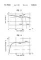
- FIG. 3is a graph showing the relationship between output voltage and input voltage of the non-contact power supply apparatus of FIG. 1;
- FIG. 4is a graph showing the relationship between output current and power transmission efficiency of the non-contact power supply apparatus of FIG. 1;
- FIG. 5is a circuit diagram of a conventional non-contact power supply apparatus.
- FIG. 1is a circuit diagram of the embodiment
- FIG. 2is a cross section of an essential portion of the embodiment in which the apparatus is installed in equipment
- FIG. 3is a graph showing the relationship between output voltage and output current at the receiving side as measured while changing distance, d, between supplying oscillating coil L1 and receiving resonance coil L3 of the embodiment of FIG. 1;
- FIG. 4is a graph showing the relationship between output current and power transmission efficiency at the receiving side as measured while changing distance, d, between supplying oscillating coil L1 and receiving resonance coil L3 of the embodiment of FIG. 1.
- the present embodimentcomprises a supplying section S and a receiving section R.
- the circuit on the leftis the supplying section S and that on the right is the receiving section R.
- Supplying section Scomprises a power supply B1 and a supplying oscillating circuit 2 which includes frequency control circuit 1.
- Receiving section Rcomprises a receiving resonance circuit 3, a rectifier circuit 4, and a smoothing circuit 5.
- the positive electrode of power supply B1is connected to neutral point ⁇ a ⁇ of an oscillating coil L1 of the aforementioned oscillating circuit 2 at the supplying side by means of a coil L4, through which power is supplied from power supply B1.
- Upper end point b and lower end point c as seen in FIG. 1 of the aforementioned oscillating coil L1are connected to frequency control circuit 1 by means of a capacitor C2.
- the aforementioned frequency control circuitcomprises a detecting coil L2, a transistor Q1, a transistor Q2, a resistor R1, and a resistor R2.
- each collectoris connected respectively to the upper end b and lower end c as viewed in FIG. 1 of oscillating coil 1
- each emitteris connected to the negative electrode of power supply B
- each basewhich is connected to its respective end points of detecting coil L2 is connected to the positive electrode of power supply B1 by means of resistor R1 and R2 respectively.
- Receiving section Rcomprises a receiving resonance circuit 3, rectifier circuit 4, and smoothing circuit 5.
- the aforementioned receiving resonance circuit 3has a resonance capacitor C3 connected in parallel with receiving resonance coil L3.
- the aforementioned rectifier circuit 4 and smoothing circuit 5are arranged by what is commonly called the choke-input rectifier method in which the rectifier circuit 4 has a diode D1 and diode D2 connected between the upper end point e and lower end point f of the receiving resonance coil 3 as seen in FIG. 1 and choke coil L5; and the smoothing circuit 5 has choke coil 5 connected between diode D1, diode D3, and load resistor R3 (which represents a battery charged by the apparatus) with smoothing capacitor C4 connected in parallel with load resistor R3.
- FIG. 2is a cross section of an essential portion of the apparatus containing this circuit.
- Supplying core Fs and Receiving core Frare positioned opposite each other, with the supplying oscillating coil L1 and detecting coil L2 wound around the supplying core Fs, and the receiving resonance coil L3 wound around the receiving core Fr.
- the power supply B1 voltageis applied to the bases of transistors Q1 and transistors Q1 through resistor R1 or resistor R2, causing current flow between the emitter and the collector of transistor Q1 which has a higher hFe value than transistor Q2.
- current flows between the emitter and collectorcurrent flows from the neutral point toward the upper end point b of the supplying oscillating coil L1 as seen in FIG. 1 and magnetic flux is generated in that direction.
- magnetic fluxis generated at the supplying oscillating coil L1, an electromotive force opposite in direction to that of the magnetic flux is induced in the detecting coil L2.
- the induced electromotive forcecauses the potential of the transistor Q1 base to drop to a lower level, and that of the transistor Q2 base to increase to a higher level, preventing current from flowing between the emitter and collector of transistor Q1 and allowing current to flow between the emitter and collector of transistor Q2. This time, current flows in the opposite direction from the neutral point ⁇ a ⁇ toward the lower end point c of supplying oscillating coil L1 as seen in FIG. 1, producing magnetic flux travelling in the same direction. The magnetic flux induces an electromotive force opposite to the above direction in detecting coil 2, which switches off transistor Q2 and switches on Q1.
- oscillationis produced by magnetic flux around supplying oscillating coil L1 which induces an electromotive force in detecting coil L2 alternately switching transistor Q1 and transistor Q2 on and off.
- rectifier circuit 4 and smoothing circuit 5are as follows.
- the two diodes D1 and D2 comprising the rectifier circuit 4operate as described below.
- the diode D1extracts the electromotive force generated from the neutral point d to the upper end point e of the resonance coil L3 on the receiving side.
- the diode D2extracts the electromotive force generated in the resonance coil L3 on the receiving side from the neutral point d to the lower end point f.
- detecting coil L2which is affected by magnetic flux produced by both oscillating coil L1 on the supplying side and the resonance coil L3 on the receiving side
- electromotive forceis induced.
- ambient conditionssuch as ambient vibrations change the distance between the oscillating coil L1 on the supplying side and coil L3 on the receiving side
- a difference in oscillating frequenciesoccurs between that of oscillating coil L1 on the supplying side and that of resonance coil L3 on the receiving side.
- an induced electromotive force having a frequency closer to the oscillating frequency on the receiving side than that on the aforementioned supplying sideacts on the bases of transistors Q1 and Q2 and turns transistors Q1 and Q2 on and off, so that the oscillating frequency of the oscillating circuit 2 on the supplying side gradually approach and eventually equal the oscillating frequency of the aforementioned resonance circuit 3 on the receiving side.
- FIG. 3shows a voltage-current relationship of load resistor R3 on the receiving side which holds when a constant voltage supply of 15 V is connected to power supply B1 and the distance, d, between the oscillating coil L1 on the supplying side and the resonance coil L3 on the receiving side is 3 mm, 4 mm, and 5.2 mm.
- the resultsreveal that an output power exceeding 10 W can be obtained if we look at, for example, the aforementioned 3-mm L1-to-L3 distance curve.
- FIG. 3reveals that at an output voltage of not more than approximately 14 V the output current is virtually constant, if we look, for example, at the aforementioned 4-mm L1-to-L3 distance curve.
- the currentbecomes constant because as the load resistor R3 resistance decreases the charge accumulated on resonance capacitor C3 of resonance circuit 3 on the receiving side flows through load resistor 3 without flowing through resonance coil L3 on the receiving side, so that resonance no longer occurs at resonance circuit 3 on the receiving side, reducing the amount of transmissible power.
- the apparatuswhich does not require a constant current circuit for charging, operates most advantageously when it is used with devices in which a charging battery is connected to a load on the receiving side.
- FIG. 4shows power transmission efficiency, that is the ratio between the power at the supplying side and that of load R3 on the receiving side, which holds when a 15 V constant voltage supply is connected to power supply B1, and the distance, d, between the oscillating coil L1 on the supplying side and resonance coil L3 on the receiving side is 3 mm and 4.5 mm. It can be seen from this Figure that the transmission efficiency of the non-contact power supply apparatus of the present embodiment is nearly 80%.
- the non-contact power supply apparatus of the present inventioncan supply sufficient power very efficiently using a simple circuit configuration even when distance between the supplying coil and the receiving coil changes by tuning each time such a change occurs.
- the apparatuscan be used as a non-contact constant current supply apparatus and be installed in numerous types of equipment such as equipment containing a charging battery.
Landscapes
- Engineering & Computer Science (AREA)
- Power Engineering (AREA)
- Computer Networks & Wireless Communication (AREA)
- Charge And Discharge Circuits For Batteries Or The Like (AREA)
Abstract
Description
Claims (7)
Applications Claiming Priority (2)
| Application Number | Priority Date | Filing Date | Title |
|---|---|---|---|
| JP4-307706 | 1992-10-21 | ||
| JP4307706AJP2803943B2 (en) | 1992-10-21 | 1992-10-21 | Non-contact power supply |
Publications (1)
| Publication Number | Publication Date |
|---|---|
| US5428521Atrue US5428521A (en) | 1995-06-27 |
Family
ID=17972261
Family Applications (1)
| Application Number | Title | Priority Date | Filing Date |
|---|---|---|---|
| US08/138,860Expired - LifetimeUS5428521A (en) | 1992-10-21 | 1993-10-19 | Non-contact power supply apparatus |
Country Status (2)
| Country | Link |
|---|---|
| US (1) | US5428521A (en) |
| JP (1) | JP2803943B2 (en) |
Cited By (46)
| Publication number | Priority date | Publication date | Assignee | Title |
|---|---|---|---|---|
| WO1998027561A1 (en)* | 1996-12-03 | 1998-06-25 | Jacques Andres | Electric supply system, corresponding terminal and mounting base |
| EP0851440A1 (en)* | 1996-12-24 | 1998-07-01 | Matsushita Electric Works, Ltd. | Noncontacting power transfer device |
| WO1998034319A1 (en)* | 1997-02-03 | 1998-08-06 | Sony Corporation | Equipment and method for transmitting electric power |
| US5898577A (en)* | 1996-02-28 | 1999-04-27 | Sony Corporation | Wireless transmitter |
| US5923544A (en)* | 1996-07-26 | 1999-07-13 | Tdk Corporation | Noncontact power transmitting apparatus |
| EP0903830A3 (en)* | 1997-09-19 | 2000-03-15 | NOKIA TECHNOLOGY GmbH | Charging device for batteries in a mobile electrical unit |
| GB2347801A (en)* | 1999-03-10 | 2000-09-13 | Ea Tech Ltd | Electric vehicle battery charger |
| US6430064B1 (en)* | 2001-06-29 | 2002-08-06 | Aichi Electric Co. Ltd. | Non-contact power supply device |
| US20020130675A1 (en)* | 2001-03-19 | 2002-09-19 | Semiconductor Energy Laboratory Co., Ltd. | Inspection method and inspection apparatus |
| US20020154518A1 (en)* | 2001-04-20 | 2002-10-24 | Reinhold Elferich | System for wireless transmission of electrical power, a garment, a system of garments and method for the transmission of signals and/or electrical energy |
| US20020173060A1 (en)* | 2001-05-15 | 2002-11-21 | Semiconductor Energy Laboratory Co., Ltd. | Measuring method, inspection method, inspection device, semiconductor device, method of manufacturing a semiconductor device, and method of manufacturing an element substrate |
| US20030103039A1 (en)* | 2001-12-04 | 2003-06-05 | Intel Corporation (A Delaware Corporation) | Inductive power source for peripheral devices |
| US20050113060A1 (en)* | 2003-10-17 | 2005-05-26 | Lowery Kenneth E. | Wireless network system |
| US20050168235A1 (en)* | 2004-01-30 | 2005-08-04 | Semiconductor Energy Laboratory Co., Ltd. | Inspection system, inspection method, and method for manufacturing semiconductor device |
| US7105365B2 (en) | 2001-03-19 | 2006-09-12 | Semiconductor Energy Laboratory Co., Ltd. | Method of manufacturing a semiconductor device |
| US20060240788A1 (en)* | 2004-05-27 | 2006-10-26 | Hiroki Iwaniya | Transmission output control circuit, and wireless device using the same |
| US20070109708A1 (en)* | 2003-05-23 | 2007-05-17 | Auckland Uniservices Limited | Methods and apparatus for control of inductively coupled power transfer systems |
| SG132529A1 (en)* | 2001-05-15 | 2007-06-28 | Semiconductor Energy Lab | Voltage measuring method, electrical test method and apparatus, semiconductor device manufacturing method and device substrate manufacturing method |
| US20090127937A1 (en)* | 2007-11-16 | 2009-05-21 | Nigelpower, Llc | Wireless Power Bridge |
| US20100290215A1 (en)* | 2009-05-12 | 2010-11-18 | Kimball International, Inc. | Furniture with wireless power |
| US20110254379A1 (en)* | 2008-11-26 | 2011-10-20 | Auckland Uniservices Limited | Bi-directional inductive power transfer |
| US20120313577A1 (en)* | 2011-06-10 | 2012-12-13 | Access Business Group International Llc | System and method for detecting, characterizing, and tracking an inductive power receiver |
| CN103107009A (en)* | 2011-11-15 | 2013-05-15 | 株式会社东芝 | Resonator and wireless power transmission device |
| US20130241304A1 (en)* | 2012-03-19 | 2013-09-19 | Lg Innotek Co., Ltd. | Wireless power transmitting apparatus and method thereof |
| EP2642627A1 (en)* | 2012-03-19 | 2013-09-25 | LG Innotek Co., Ltd. | Wireless power receiver and wireless power transferring method |
| US8811901B2 (en) | 2010-07-30 | 2014-08-19 | Semiconductor Energy Laboratory Co., Ltd. | Wireless power feeding system and wireless power feeding method |
| US8836170B2 (en) | 2010-07-28 | 2014-09-16 | Semiconductor Energy Laboratory Co., Ltd. | Wireless power feeding system and wireless power feeding method |
| US8901777B2 (en) | 2010-07-30 | 2014-12-02 | Semiconductor Energy Laboratory Co., Ltd. | Wireless power feeding system and wireless power feeding method |
| US9024482B2 (en) | 2011-01-20 | 2015-05-05 | Semiconductor Energy Laboratory Co., Ltd. | Power feeding device and wireless power feeding system |
| US9054548B2 (en) | 2011-09-16 | 2015-06-09 | Semiconductor Energy Laboratory Co., Ltd. | Contactless power feeding system |
| US9054544B2 (en) | 2010-12-22 | 2015-06-09 | Semiconductor Energy Laboratory Co., Ltd. | Power feeding device, power receiving device, and wireless power feed system |
| US9065302B2 (en) | 2010-12-24 | 2015-06-23 | Semiconductor Energy Laboratory Co., Ltd. | Wireless power feeding system |
| US9124308B2 (en) | 2009-05-12 | 2015-09-01 | Kimball International, Inc. | Furniture with wireless power |
| US9143011B2 (en) | 2011-09-29 | 2015-09-22 | Semiconductor Energy Laboratory Co., Ltd. | Power receiving device and contactless power feeding system |
| US9231429B2 (en) | 2011-12-23 | 2016-01-05 | Semiconductor Energy Laboratory Co., Ltd. | Power receiving device and wireless power supply system |
| US9246357B2 (en) | 2011-12-07 | 2016-01-26 | Semiconductor Energy Laboratory Co., Ltd. | Contactless power feeding system |
| US9325205B2 (en) | 2011-03-04 | 2016-04-26 | Semiconductor Energy Laboratory Co., Ltd. | Method for driving power supply system |
| WO2016064283A1 (en)* | 2014-10-22 | 2016-04-28 | Powerbyproxi Limited | A converter |
| US9391674B2 (en) | 2012-04-26 | 2016-07-12 | Semiconductor Energy Laboratory Co., Ltd. | Power feeding system and power feeding method |
| US9390850B2 (en) | 2012-07-13 | 2016-07-12 | Semiconductor Energy Laboratory Co., Ltd. | Power transmitting device, power feeding system, and power feeding method |
| US9391476B2 (en) | 2010-09-09 | 2016-07-12 | Semiconductor Energy Laboratory Co., Ltd. | Power feeding device, wireless power feeding system using the same and wireless power feeding method |
| US9461476B2 (en) | 2010-11-26 | 2016-10-04 | Semiconductor Energy Laboratory Co., Ltd. | Power transmission device and wireless power transmission system including the same |
| US9477249B2 (en) | 2011-12-16 | 2016-10-25 | Semiconductor Energy Laboratory Co., Ltd. | DC-DC converter, power receiving device, and power feeding system |
| US10038389B2 (en) | 2011-11-10 | 2018-07-31 | Apple Inc. | Method for controlling a converter |
| US10819154B2 (en) | 2016-09-06 | 2020-10-27 | Apple Inc. | Inductive power transmitter |
| US20220074042A1 (en)* | 2018-12-19 | 2022-03-10 | Posco | Apparatus and method for controlling coating layer in pvd plating process |
Families Citing this family (11)
| Publication number | Priority date | Publication date | Assignee | Title |
|---|---|---|---|---|
| JPH0879976A (en)* | 1994-09-07 | 1996-03-22 | Tdk Corp | Non-contact type charger |
| JP3247328B2 (en)* | 1997-12-09 | 2002-01-15 | 浩 坂本 | Non-contact power transmission device |
| JP3743193B2 (en)* | 1999-02-23 | 2006-02-08 | 松下電工株式会社 | Non-contact power transmission device |
| JP2003142327A (en)* | 2001-10-31 | 2003-05-16 | Furukawa Electric Co Ltd:The | Non-contact power supply |
| US7489526B2 (en)* | 2004-08-20 | 2009-02-10 | Analog Devices, Inc. | Power and information signal transfer using micro-transformers |
| JP4987650B2 (en)* | 2007-09-21 | 2012-07-25 | 東光株式会社 | Rotating toy |
| KR101679580B1 (en) | 2009-10-16 | 2016-11-29 | 삼성전자주식회사 | Wireless Power Transmission Device, Wireless Power Transmission Controlling Device and Wireless Power Transmission Method |
| US8669677B2 (en)* | 2010-12-28 | 2014-03-11 | Tdk Corporation | Wireless power feeder, wireless power receiver, and wireless power transmission system |
| JP5657415B2 (en)* | 2011-02-16 | 2015-01-21 | 東光株式会社 | Wireless power transmission equipment |
| JP7615640B2 (en)* | 2020-12-01 | 2025-01-17 | オムロン株式会社 | Remaining life prediction device and method |
| JPWO2024162274A1 (en)* | 2023-02-01 | 2024-08-08 |
Citations (4)
| Publication number | Priority date | Publication date | Assignee | Title |
|---|---|---|---|---|
| US4422032A (en)* | 1980-02-14 | 1983-12-20 | Matsushita Electric Works, Ltd. | Battery charging circuit for maintaining a substantially constant average value of charging current despite variations in charging voltage |
| US4504874A (en)* | 1981-07-23 | 1985-03-12 | Olympus Optical Co., Ltd. | Tape recorder |
| US4811187A (en)* | 1985-02-12 | 1989-03-07 | Hitachi Metals Ltd. | DC-DC converter with saturable reactor reset circuit |
| US5225972A (en)* | 1991-03-20 | 1993-07-06 | Hiroshi Sakamoto | Power source |
Family Cites Families (4)
| Publication number | Priority date | Publication date | Assignee | Title |
|---|---|---|---|---|
| JPS5817506A (en)* | 1981-07-23 | 1983-02-01 | Olympus Optical Co Ltd | Tape recorder |
| JPS6289478A (en)* | 1985-02-12 | 1987-04-23 | Hitachi Metals Ltd | Dc/dc converter |
| JPH0398432A (en)* | 1989-09-11 | 1991-04-24 | Eito Denshi:Kk | Power supply through electromagnetic induction |
| US5095224A (en)* | 1990-08-31 | 1992-03-10 | Siemens-Pacesetter, Inc. | Interrupted resonance energy transfer system |
- 1992
- 1992-10-21JPJP4307706Apatent/JP2803943B2/ennot_activeExpired - Fee Related
- 1993
- 1993-10-19USUS08/138,860patent/US5428521A/ennot_activeExpired - Lifetime
Patent Citations (4)
| Publication number | Priority date | Publication date | Assignee | Title |
|---|---|---|---|---|
| US4422032A (en)* | 1980-02-14 | 1983-12-20 | Matsushita Electric Works, Ltd. | Battery charging circuit for maintaining a substantially constant average value of charging current despite variations in charging voltage |
| US4504874A (en)* | 1981-07-23 | 1985-03-12 | Olympus Optical Co., Ltd. | Tape recorder |
| US4811187A (en)* | 1985-02-12 | 1989-03-07 | Hitachi Metals Ltd. | DC-DC converter with saturable reactor reset circuit |
| US5225972A (en)* | 1991-03-20 | 1993-07-06 | Hiroshi Sakamoto | Power source |
Cited By (108)
| Publication number | Priority date | Publication date | Assignee | Title |
|---|---|---|---|---|
| US5898577A (en)* | 1996-02-28 | 1999-04-27 | Sony Corporation | Wireless transmitter |
| US5923544A (en)* | 1996-07-26 | 1999-07-13 | Tdk Corporation | Noncontact power transmitting apparatus |
| WO1998027561A1 (en)* | 1996-12-03 | 1998-06-25 | Jacques Andres | Electric supply system, corresponding terminal and mounting base |
| FR2765736A1 (en)* | 1996-12-03 | 1999-01-08 | Jacques Patrick Andres | SYSTEM FOR THE SUPPLY OF ELECTRICAL ENERGY, PARTICULARLY OUTSIDE AND IN PUBLIC PLACES, CORRESPONDING TERMINAL AND BASE |
| US6219267B1 (en) | 1996-12-03 | 2001-04-17 | Jacques Andres | Electric supply system, corresponding terminal and mounting base |
| EP0851440A1 (en)* | 1996-12-24 | 1998-07-01 | Matsushita Electric Works, Ltd. | Noncontacting power transfer device |
| CN1069999C (en)* | 1996-12-24 | 2001-08-22 | 松下电工株式会社 | Non-contact electric power distribution device |
| WO1998034319A1 (en)* | 1997-02-03 | 1998-08-06 | Sony Corporation | Equipment and method for transmitting electric power |
| EP0903830A3 (en)* | 1997-09-19 | 2000-03-15 | NOKIA TECHNOLOGY GmbH | Charging device for batteries in a mobile electrical unit |
| GB2347801A (en)* | 1999-03-10 | 2000-09-13 | Ea Tech Ltd | Electric vehicle battery charger |
| GB2347801B (en)* | 1999-03-10 | 2001-01-17 | Ea Tech Ltd | Battery chargers |
| US7105365B2 (en) | 2001-03-19 | 2006-09-12 | Semiconductor Energy Laboratory Co., Ltd. | Method of manufacturing a semiconductor device |
| US20060263952A1 (en)* | 2001-03-19 | 2006-11-23 | Semiconductor Energy Laboratory Co., Ltd. | Method of manufacturing a semiconductor device |
| US20090212792A1 (en)* | 2001-03-19 | 2009-08-27 | Semiconductor Energy Laboratory Co., Ltd. | Inspection Method and Inspection Apparatus |
| US7674635B2 (en) | 2001-03-19 | 2010-03-09 | Semiconductor Energy Laboratory Co., Ltd. | Method of manufacturing a semiconductor device |
| US7902845B2 (en) | 2001-03-19 | 2011-03-08 | Semiconductor Energy Laboratory Co., Ltd. | Inspection method and inspection apparatus |
| US20110148220A1 (en)* | 2001-03-19 | 2011-06-23 | Semiconductor Energy Laboratory Co., Ltd. | Inspection Method and Inspection Apparatus |
| US6850080B2 (en) | 2001-03-19 | 2005-02-01 | Semiconductor Energy Laboratory Co., Ltd. | Inspection method and inspection apparatus |
| US20020130675A1 (en)* | 2001-03-19 | 2002-09-19 | Semiconductor Energy Laboratory Co., Ltd. | Inspection method and inspection apparatus |
| US8664967B2 (en) | 2001-03-19 | 2014-03-04 | Semiconductor Energy Laboratory Co., Ltd. | Inspection method and inspection apparatus |
| US9047796B2 (en) | 2001-03-19 | 2015-06-02 | Semiconductor Energy Laboratory Co., Ltd. | Method of manufacturing a semiconductor device |
| US20050212044A1 (en)* | 2001-03-19 | 2005-09-29 | Semiconductor Energy Laboratory Co., Ltd. | Inspection method and inspection apparatus |
| US8729548B2 (en) | 2001-03-19 | 2014-05-20 | Semiconductor Energy Laboratory Co., Ltd. | Method of manufacturing a semiconductor device |
| US7532018B2 (en) | 2001-03-19 | 2009-05-12 | Semiconductor Energy Laboratory Co., Ltd. | Inspection method and inspection apparatus |
| US7076206B2 (en) | 2001-04-20 | 2006-07-11 | Koninklijke Philips Electronics, N.V. | System for wireless transmission of electrical power, a garment, a system of garments and method for the transmission of signals and/or electrical energy |
| EP1253695A3 (en)* | 2001-04-20 | 2003-01-22 | Philips Corporate Intellectual Property GmbH | System for wireless transmission of electrical power and signals and system of garments |
| US20020154518A1 (en)* | 2001-04-20 | 2002-10-24 | Reinhold Elferich | System for wireless transmission of electrical power, a garment, a system of garments and method for the transmission of signals and/or electrical energy |
| US20050218926A1 (en)* | 2001-05-15 | 2005-10-06 | Masaaki Hiroki | Measuring method, inspection method, inspection device, semiconductor device, method of manufacturing a semiconductor device, and method of manufacturing an element substrate |
| US6891391B2 (en)* | 2001-05-15 | 2005-05-10 | Semiconductor Energy Laboratory Co., Ltd. | Measuring method, inspection method, inspection device, semiconductor device, method of manufacturing a semiconductor device, and method of manufacturing an element substrate |
| US8193827B2 (en) | 2001-05-15 | 2012-06-05 | Semiconductor Energy Laboratory Co., Ltd. | Measuring method, inspection method, inspection device, semiconductor device, method of manufacturing a semiconductor device, and method of manufacturing an element substrate |
| SG132529A1 (en)* | 2001-05-15 | 2007-06-28 | Semiconductor Energy Lab | Voltage measuring method, electrical test method and apparatus, semiconductor device manufacturing method and device substrate manufacturing method |
| US20020173060A1 (en)* | 2001-05-15 | 2002-11-21 | Semiconductor Energy Laboratory Co., Ltd. | Measuring method, inspection method, inspection device, semiconductor device, method of manufacturing a semiconductor device, and method of manufacturing an element substrate |
| US6430064B1 (en)* | 2001-06-29 | 2002-08-06 | Aichi Electric Co. Ltd. | Non-contact power supply device |
| US7180503B2 (en)* | 2001-12-04 | 2007-02-20 | Intel Corporation | Inductive power source for peripheral devices |
| US20030103039A1 (en)* | 2001-12-04 | 2003-06-05 | Intel Corporation (A Delaware Corporation) | Inductive power source for peripheral devices |
| US8093758B2 (en)* | 2003-05-23 | 2012-01-10 | Auckland Uniservices Limited | Method and apparatus for control of inductively coupled power transfer systems |
| US20070109708A1 (en)* | 2003-05-23 | 2007-05-17 | Auckland Uniservices Limited | Methods and apparatus for control of inductively coupled power transfer systems |
| US20050113060A1 (en)* | 2003-10-17 | 2005-05-26 | Lowery Kenneth E. | Wireless network system |
| US7112952B2 (en) | 2004-01-30 | 2006-09-26 | Semiconductor Energy Laboratory Co., Ltd. | Inspection system, inspection method, and method for manufacturing semiconductor device |
| US7667454B2 (en) | 2004-01-30 | 2010-02-23 | Semiconductor Energy Laboratory Co., Ltd. | Inspection system, inspection method, and method for manufacturing semiconductor device |
| US7463049B2 (en) | 2004-01-30 | 2008-12-09 | Semiconductor Energy Laboratory Co., Ltd. | Inspection method for semiconductor device |
| US7276929B2 (en) | 2004-01-30 | 2007-10-02 | Semiconductor Energy Laboratory Co., Ltd. | Inspection system, inspection method, and method for manufacturing semiconductor device |
| US20050168235A1 (en)* | 2004-01-30 | 2005-08-04 | Semiconductor Energy Laboratory Co., Ltd. | Inspection system, inspection method, and method for manufacturing semiconductor device |
| US20090087930A1 (en)* | 2004-01-30 | 2009-04-02 | Semiconductor Energy Laboratory Co., Ltd. | Inspection System, Inspection Method, and Method for Manufacturing Semiconductor Device |
| US20070013397A1 (en)* | 2004-01-30 | 2007-01-18 | Semiconductor Energy Laboratory Co., Ltd. | Inspection system, inspection method, and method for manufacturing semiconductor device |
| US20080024156A1 (en)* | 2004-01-30 | 2008-01-31 | Semiconductor Energy Laboratory Co., Ltd. | Inspection System, Inspection Method, and Method for Manufacturing Semiconductor Device |
| US7299015B2 (en)* | 2004-05-27 | 2007-11-20 | Matsushita Electric Industrial Co., Ltd. | Transmission output control circuit, and wireless device using the same |
| US20060240788A1 (en)* | 2004-05-27 | 2006-10-26 | Hiroki Iwaniya | Transmission output control circuit, and wireless device using the same |
| US9966188B2 (en) | 2007-11-16 | 2018-05-08 | Qualcomm Incorporated | Wireless power bridge |
| US20090127937A1 (en)* | 2007-11-16 | 2009-05-21 | Nigelpower, Llc | Wireless Power Bridge |
| US8729734B2 (en) | 2007-11-16 | 2014-05-20 | Qualcomm Incorporated | Wireless power bridge |
| US20110254379A1 (en)* | 2008-11-26 | 2011-10-20 | Auckland Uniservices Limited | Bi-directional inductive power transfer |
| US10355526B2 (en)* | 2008-11-26 | 2019-07-16 | Auckland Uniservices Limited | Bi-directional inductive power transfer |
| US10432026B2 (en) | 2008-11-26 | 2019-10-01 | Auckland Uniservices Limited | Primary-side power control for inductive power transfer |
| US9461480B2 (en) | 2008-11-26 | 2016-10-04 | Auckland Uniservices Limited | Primary-side power control for inductive power transfer |
| US8923015B2 (en) | 2008-11-26 | 2014-12-30 | Auckland Uniservices Limited | Primary-side power control for inductive power transfer |
| US8061864B2 (en) | 2009-05-12 | 2011-11-22 | Kimball International, Inc. | Furniture with wireless power |
| US9124308B2 (en) | 2009-05-12 | 2015-09-01 | Kimball International, Inc. | Furniture with wireless power |
| US20100290215A1 (en)* | 2009-05-12 | 2010-11-18 | Kimball International, Inc. | Furniture with wireless power |
| US8262244B2 (en) | 2009-05-12 | 2012-09-11 | Kimball International, Inc. | Furniture with wireless power |
| US9572424B2 (en) | 2009-05-12 | 2017-02-21 | Kimball International, Inc. | Furniture with wireless power |
| US8836170B2 (en) | 2010-07-28 | 2014-09-16 | Semiconductor Energy Laboratory Co., Ltd. | Wireless power feeding system and wireless power feeding method |
| US9472974B2 (en) | 2010-07-28 | 2016-10-18 | Semiconductor Energy Laboratory Co., Ltd. | Wireless power feeding system and wireless power feeding method |
| US8811901B2 (en) | 2010-07-30 | 2014-08-19 | Semiconductor Energy Laboratory Co., Ltd. | Wireless power feeding system and wireless power feeding method |
| US8901777B2 (en) | 2010-07-30 | 2014-12-02 | Semiconductor Energy Laboratory Co., Ltd. | Wireless power feeding system and wireless power feeding method |
| US10110068B2 (en) | 2010-07-30 | 2018-10-23 | Semiconductor Energy Laboratories Co., Ltd. | Wireless power feeding system and wireless power feeding method |
| US9391476B2 (en) | 2010-09-09 | 2016-07-12 | Semiconductor Energy Laboratory Co., Ltd. | Power feeding device, wireless power feeding system using the same and wireless power feeding method |
| US10044224B2 (en) | 2010-09-09 | 2018-08-07 | Semiconductor Energy Laboratory Co., Ltd. | Power feeding device, wireless power feeding system using the same and wireless power feeding method |
| US9461476B2 (en) | 2010-11-26 | 2016-10-04 | Semiconductor Energy Laboratory Co., Ltd. | Power transmission device and wireless power transmission system including the same |
| US9912170B2 (en) | 2010-12-22 | 2018-03-06 | Semiconductor Energy Laboratory Co., Ltd. | Power feeding device, power receiving device, and wireless power feed system |
| US9054544B2 (en) | 2010-12-22 | 2015-06-09 | Semiconductor Energy Laboratory Co., Ltd. | Power feeding device, power receiving device, and wireless power feed system |
| US11843259B2 (en) | 2010-12-22 | 2023-12-12 | Semiconductor Energy Laboratory Co., Ltd. | Power feeding device, power receiving device, and wireless power feed system |
| US11424622B2 (en) | 2010-12-22 | 2022-08-23 | Semiconductor Energy Laboratory Co., Ltd. | Power feeding device, power receiving device, and wireless power feed system |
| US9065302B2 (en) | 2010-12-24 | 2015-06-23 | Semiconductor Energy Laboratory Co., Ltd. | Wireless power feeding system |
| US9024482B2 (en) | 2011-01-20 | 2015-05-05 | Semiconductor Energy Laboratory Co., Ltd. | Power feeding device and wireless power feeding system |
| US10491183B2 (en) | 2011-01-20 | 2019-11-26 | Semiconductor Energy Laboratory Co., Ltd. | Power feeding device and wireless power feeding system |
| US9837977B2 (en) | 2011-01-20 | 2017-12-05 | Semiconductor Energy Laboratory Co., Ltd. | Power feeding device and wireless power feeding system |
| US9325205B2 (en) | 2011-03-04 | 2016-04-26 | Semiconductor Energy Laboratory Co., Ltd. | Method for driving power supply system |
| US20120313577A1 (en)* | 2011-06-10 | 2012-12-13 | Access Business Group International Llc | System and method for detecting, characterizing, and tracking an inductive power receiver |
| US9054548B2 (en) | 2011-09-16 | 2015-06-09 | Semiconductor Energy Laboratory Co., Ltd. | Contactless power feeding system |
| US9143011B2 (en) | 2011-09-29 | 2015-09-22 | Semiconductor Energy Laboratory Co., Ltd. | Power receiving device and contactless power feeding system |
| US10038389B2 (en) | 2011-11-10 | 2018-07-31 | Apple Inc. | Method for controlling a converter |
| CN103107009B (en)* | 2011-11-15 | 2016-05-11 | 株式会社东芝 | Resonator and wireless power transmission apparatus |
| CN103107009A (en)* | 2011-11-15 | 2013-05-15 | 株式会社东芝 | Resonator and wireless power transmission device |
| EP2595161A1 (en)* | 2011-11-15 | 2013-05-22 | Kabushiki Kaisha Toshiba | Resonator and wireless power transmission device |
| US9564760B2 (en) | 2011-12-07 | 2017-02-07 | Semiconductor Energy Laboratory Co., Ltd. | Contactless power feeding system |
| US9246357B2 (en) | 2011-12-07 | 2016-01-26 | Semiconductor Energy Laboratory Co., Ltd. | Contactless power feeding system |
| US9998003B2 (en) | 2011-12-16 | 2018-06-12 | Semiconductor Energy Laboratory Co., Ltd. | DC-DC converter, power receiving device, and power feeding system |
| US9477249B2 (en) | 2011-12-16 | 2016-10-25 | Semiconductor Energy Laboratory Co., Ltd. | DC-DC converter, power receiving device, and power feeding system |
| US9231429B2 (en) | 2011-12-23 | 2016-01-05 | Semiconductor Energy Laboratory Co., Ltd. | Power receiving device and wireless power supply system |
| US10020670B2 (en) | 2011-12-23 | 2018-07-10 | Semiconductor Energy Laboratory Co., Ltd. | Power receiving device and wireless power supply system |
| US9246400B2 (en) | 2012-03-19 | 2016-01-26 | Lg Innotek Co., Ltd. | Wireless power receiver and wireless power transferring method |
| USRE49017E1 (en)* | 2012-03-19 | 2022-04-05 | Lg Innotek Co., Ltd. | Wireless power transmitting apparatus and method thereof |
| US20130241304A1 (en)* | 2012-03-19 | 2013-09-19 | Lg Innotek Co., Ltd. | Wireless power transmitting apparatus and method thereof |
| USRE49955E1 (en)* | 2012-03-19 | 2024-04-30 | Lg Innotek Co., Ltd. | Wireless power transmitting apparatus and method thereof |
| US9225391B2 (en)* | 2012-03-19 | 2015-12-29 | Lg Innotek Co., Ltd. | Wireless power transmitting apparatus and method thereof |
| EP2642627A1 (en)* | 2012-03-19 | 2013-09-25 | LG Innotek Co., Ltd. | Wireless power receiver and wireless power transferring method |
| US20160111895A1 (en)* | 2012-03-19 | 2016-04-21 | Lg Innotek Co., Ltd. | Wireless power transmitting apparatus and method thereof |
| CN103326474A (en)* | 2012-03-19 | 2013-09-25 | Lg伊诺特有限公司 | Wireless power receiver and wireless power transmission method |
| US9711974B2 (en)* | 2012-03-19 | 2017-07-18 | Lg Innotek Co., Ltd. | Wireless power transmitting apparatus and method thereof |
| US9601942B2 (en) | 2012-03-19 | 2017-03-21 | Lg Innotek Co., Ltd. | Wireless power receiver and wireless power transferring method |
| US9391674B2 (en) | 2012-04-26 | 2016-07-12 | Semiconductor Energy Laboratory Co., Ltd. | Power feeding system and power feeding method |
| US9941746B2 (en) | 2012-07-13 | 2018-04-10 | Semiconductor Energy Laboratory Co., Ltd. | Power transmitting device, power feeding system, and power feeding method |
| US9390850B2 (en) | 2012-07-13 | 2016-07-12 | Semiconductor Energy Laboratory Co., Ltd. | Power transmitting device, power feeding system, and power feeding method |
| CN107078651A (en)* | 2014-10-22 | 2017-08-18 | 鲍尔拜普罗克西有限公司 | Converter |
| WO2016064283A1 (en)* | 2014-10-22 | 2016-04-28 | Powerbyproxi Limited | A converter |
| US10819154B2 (en) | 2016-09-06 | 2020-10-27 | Apple Inc. | Inductive power transmitter |
| US20220074042A1 (en)* | 2018-12-19 | 2022-03-10 | Posco | Apparatus and method for controlling coating layer in pvd plating process |
Also Published As
| Publication number | Publication date |
|---|---|
| JPH06178464A (en) | 1994-06-24 |
| JP2803943B2 (en) | 1998-09-24 |
Similar Documents
| Publication | Publication Date | Title |
|---|---|---|
| US5428521A (en) | Non-contact power supply apparatus | |
| US6040986A (en) | Non-contact power transmitting device having simplified self-oscillation feedback loop which interrupts power transmission when no load is present | |
| EP0055064B2 (en) | DC-DC converter | |
| US4992702A (en) | Inverter capable of controlling operating frequency | |
| US6366480B2 (en) | Switching power supply apparatus | |
| JP3416863B2 (en) | Power supply | |
| US5864472A (en) | Apparatus for controlling a multiresonant self-oscillating converter circuit | |
| JP2003047179A (en) | Contactless electric power transmission device | |
| US6917528B2 (en) | Switching power transmission device | |
| Sakamoto et al. | A novel circuit for non-contact charging through electro-magnetic coupling | |
| US6016259A (en) | Power supply circuit | |
| US4334267A (en) | Free-running push-pull inverter | |
| CA1290817C (en) | Power supply apparatus | |
| JPH0691750B2 (en) | Inverter device | |
| JPH05300662A (en) | Charger | |
| EP0391679B1 (en) | Oscillator circuit | |
| KR900008542B1 (en) | Power of microwave heating device | |
| EP0388492B1 (en) | Inverter capable of controlling operating frequency | |
| JP2003037949A (en) | Non-contact power transmission device | |
| EP0058035A1 (en) | Transistor inverter device | |
| JP2003037950A (en) | Non-contact power transmission device | |
| JPH0713431Y2 (en) | Power supply circuit | |
| CA2211467C (en) | Inverter for the power supply of discharge lamps with means for improving the power factor | |
| KR920000361B1 (en) | High Efficiency Base Driver Circuit for Ringing Choke Converter | |
| JPS5839285A (en) | Transistor inverter device |
Legal Events
| Date | Code | Title | Description |
|---|---|---|---|
| AS | Assignment | Owner name:KIGAWA ELECTRONIC ENGINEERING LABORATORY, INC., JA Free format text:ASSIGNMENT OF ASSIGNORS INTEREST;ASSIGNORS:HIGUCHI, SHINICHI;KIGAWA, MICHIO;REEL/FRAME:007166/0238 Effective date:19940717 Owner name:ALPS ELECTRIC CO., LTD., JAPAN Free format text:ASSIGNMENT OF ASSIGNORS INTEREST;ASSIGNORS:HIGUCHI, SHINICHI;KIGAWA, MICHIO;REEL/FRAME:007166/0238 Effective date:19940717 | |
| FEPP | Fee payment procedure | Free format text:PAYOR NUMBER ASSIGNED (ORIGINAL EVENT CODE: ASPN); ENTITY STATUS OF PATENT OWNER: LARGE ENTITY | |
| STCF | Information on status: patent grant | Free format text:PATENTED CASE | |
| FPAY | Fee payment | Year of fee payment:4 | |
| FEPP | Fee payment procedure | Free format text:PAYOR NUMBER ASSIGNED (ORIGINAL EVENT CODE: ASPN); ENTITY STATUS OF PATENT OWNER: LARGE ENTITY Free format text:PAYER NUMBER DE-ASSIGNED (ORIGINAL EVENT CODE: RMPN); ENTITY STATUS OF PATENT OWNER: LARGE ENTITY | |
| FPAY | Fee payment | Year of fee payment:8 | |
| FPAY | Fee payment | Year of fee payment:12 |