US5428491A - Magnetoresistive head with deposited biasing magnet - Google Patents
Magnetoresistive head with deposited biasing magnetDownload PDFInfo
- Publication number
- US5428491A US5428491AUS08/161,298US16129893AUS5428491AUS 5428491 AUS5428491 AUS 5428491AUS 16129893 AUS16129893 AUS 16129893AUS 5428491 AUS5428491 AUS 5428491A
- Authority
- US
- United States
- Prior art keywords
- permanent magnet
- magnetoresistive element
- magnetoresistive
- head
- length
- Prior art date
- Legal status (The legal status is an assumption and is not a legal conclusion. Google has not performed a legal analysis and makes no representation as to the accuracy of the status listed.)
- Expired - Lifetime
Links
Images

Classifications
- G—PHYSICS
- G11—INFORMATION STORAGE
- G11B—INFORMATION STORAGE BASED ON RELATIVE MOVEMENT BETWEEN RECORD CARRIER AND TRANSDUCER
- G11B5/00—Recording by magnetisation or demagnetisation of a record carrier; Reproducing by magnetic means; Record carriers therefor
- G11B5/127—Structure or manufacture of heads, e.g. inductive
- G11B5/33—Structure or manufacture of flux-sensitive heads, i.e. for reproduction only; Combination of such heads with means for recording or erasing only
- G11B5/39—Structure or manufacture of flux-sensitive heads, i.e. for reproduction only; Combination of such heads with means for recording or erasing only using magneto-resistive devices or effects
- G11B5/3903—Structure or manufacture of flux-sensitive heads, i.e. for reproduction only; Combination of such heads with means for recording or erasing only using magneto-resistive devices or effects using magnetic thin film layers or their effects, the films being part of integrated structures
- G11B5/3906—Details related to the use of magnetic thin film layers or to their effects
- G11B5/3929—Disposition of magnetic thin films not used for directly coupling magnetic flux from the track to the MR film or for shielding
- G11B5/3932—Magnetic biasing films
Definitions
- This inventionrelates to a thin film magnetoresistive reproduce head having a thin film permanent magnet for biasing the magnetoresistive element in the magnetoresistive head.
- magnetoresistive (MR) reproduce headsare increasingly recognized as the technology of choice.
- Two technological hurdlespresently stand in the way of practical application of MR heads: the establishment of an optimum bias magnetization distribution for linearization of the reproduce signal; and stabilization of domain-wall-free, quasi-single domain magnetization throughout the central (active) region of the MR element.
- Permanent magnet (PM) biasing methodsare particularly attractive in that they require no power dissipation, nor entail any loss of signal due to shunting of the MR sense current.
- the MR headgenerally designated as 10, includes: (1) a PM element 12 deposited on a substrate (not shown) and magnetized in the direction of arrow A; and an MR element 14 deposited over the PM element on the substrate.
- the MR headwill always be designated 10
- the PM elementwill be designated as 12
- the MR elementwill be designated 14.
- the deposited PM element 12provides a very spatially non-uniform longitudinal stabilization field which complementarily cancels the similarly non-uniform internal demagnetization field of the MR element 14 (which is the fundamental source of single domain instability).
- the underlying deposited PM elementdoes not apply excessive longitudinal field to the central active area of the MR element 14, which would reduce the reproduce sensitivity of the MR head.
- a problem with the MR head taught in the '158 patentis that the relatively large magnetic field at the edge of the PM element 12 adjacent the head medium interface can distort the information recorded on the magnetic medium.
- Yet another problem with the MR headarises because the inhomogeneities in the closely adjacent PM can perturb the magnetic and/or the reproduce properties of the MR element.
- the PM headpositions the PM adjacent to the planar surface of the MR head. When the PM is in this position, local stray fields from inhomogeneities in the PM film have a degrading effect on the magnetic configuration of the MR element.
- U.S. Pat. No. 4,972,284 issued Nov. 20, 1990 to Smith et alteaches an alternative configuration for a deposited PM element which simultaneously provides both a transverse field for establishing a bias magnetization in the MR element, and a unidirectional longitudinal field component for maintaining a domain-wall-free magnetization state in the active region of the MR element.
- the deposited PM elementis in the shape of a "C" or "L” and the PM element is coplanar with the MR element. As shown in FIG. 3, the C-shaped PM element 12 is located adjacent and in the same plane as the MR element 14.
- the PM element 12is magnetized at an angle ⁇ with respect to its longitudinal axis, thereby providing both a transverse field for establishing a bias magnetization in the MR element, and a unidirectional longitudinal field component for maintaining a domain-wall-free magnetization state in the active region of the MR element. Since the PM element 12 is located away from the head-medium interface, this geometry has the advantage that the PM element 12 is encapsulated in the integrated head and is therefore not exposed to corrosion at the head-medium interface 16. It has the further advantage that the PM element 12 is located a distance from the head-medium interface 16 and is therefore unlikely to distort the information recorded on the magnetic medium. However, the geometry disclosed in the '284 patent has the drawback that the longitudinal component of the magnetic field produced by the PM element 12 is more uniform along the length of the MR element than is desirable for optimum reproduce sensitivity.
- a thin film deposited magnetoresistive headhas a rectangular thin film magnetoresistive element; a thin film permanent magnet has a rectangular body longer than said magnetoresistive element, and is arranged coplanar and parallel with the magnetoresistive element, the permanent magnet having a first set of end tabs extending in the width direction from the rectangular body, the magnetoresistive element being located between the end tabs such that the permanent magnet provides a magnetic field component parallel to the length of the magnetoresistive element for stabilizing a domain-wall-free magnetization distribution in the magnetoresistive element.
- the permanent magnetfurther includes a second set of end tabs extending in the width direction away from the magnetoresistive element.
- the magnetoresistive elementis a dual magnetoresistive element.
- the magnetoresistive headhas the advantages of having improved sensitivity while the permanent magnet layer is located farther away from the head medium interface and is less likely to distort the information recorded on the medium.
- the mediumis also located further away from the MR element and is less likely to perturb it.
- the PM of the present inventioncan provide much larger gradients in the longitudinal components of the bias field and large bias fields at the end of the MR element.
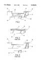
- FIG. 1is a diagram of an MR head having a permanent biasing magnet according to the present invention.
- FIG. 2is a diagram of an MR head having an overlying permanent biasing magnet according to the prior art.
- FIG. 3is a diagram of an MR head having a coplanar biasing magnet according to the prior art.
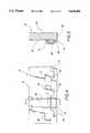
- FIG. 4is a plan view of a portion of a multitrack MR head according to the present invention.
- FIG. 5is a cross sectional view taken along line 5--5 of the MR head shown in FIG. 4.
- FIG. 6is a diagram of a dual-magnetoresistive head having a permanent biasing magnet according to the present invention.
- FIG. 7is a diagram of a dual-magnetoresistive head including a permanent biasing magnet according to the present invention, including a central tab for reducing the longitudinal biasing field near the middle of the dual-magnetoresistive element.
- FIG. 8is a diagram of a dual-magnetoresistive head including a permanent biasing magnet according to the present invention, including a pair of gaps for providing a path for electrical leads.
- FIG. 1shows an MR head 10 according to the present invention.
- the PM element 12is similar in construction to the prior art PM element 12 shown in FIG. 3, and additionally includes a pair of end tabs 20 that extend from the PM element 12 in a width direction, with the MR element 14 being located between the end tabs 20.
- the PM element 12is a magnetically homogenous permanent magnet material that is magnetized at an angle ⁇ of approximately 45 degrees from its longitudinal axis, thus providing both a transverse and longitudinal component of magnetic field.
- the end tabs 20in cooperation with the longitudinal portion 22 of the PM element 12 between the end tabs cause the longitudinal component of the magnetic field to be highly nonuniform (strong at the ends and weak near the middle) along the MR element 14, thereby maximizing the single domain stability of the MR element while minimizing sensitivity loss of the MR head.
- a portion of a multitrack MR headcan include a linear array of MR elements 14, each with its own PM biasing magnet, deposited on a substrate 24.
- the PM elements 12are formed using materials such as CoPt or CoSm according to the techniques known in the art.
- the PM elements 12may be covered by a thin layer 26 of electrically insulating material such as SiO 2 .
- Deposited leads 28are formed in electrical contact with the MR elements 14 for conducting externally generated sense currents through the MR elements as is well known in the art.
- the MR head 10is placed in a strong external magnetic field which magnetizes the PM elements 12 in the desired direction determined by the direction of the external field.
- the direction of magnetizationis selected to provide the desired magnitudes of hard and easy axis biasing.
- the thickness of the MR elements 14 and PM elements 12may not be of equal thickness, they are both deposited approximately on the common plane of the surface of substrate 24.
- the DMR headincludes a pair of MR elements 14 and 14' that are deposited one on top of the other as taught by U.S. Pat. No. 5,084,795.
- the sense currents flowing in the DMR elementscause them to mutually bias each other in the hard axis direction.
- the PM element 12is employed to bias the MR elements in the easy axis direction.
- the PM element 12is magnetized in the longitudinal direction.
- the end tabs 20generate a strong longitudinal field at the ends of the MR elements 14 and 14'.
- a small deviation ⁇ in the magnetization direction from the longitudinal axismay be incorporated in the PM element 12 to compensate for any thickness mismatch in the MR elements 14 and 14'.
- the electrical contact leads and insulating layer between the MR elementsare not shown in FIG. 6, but are assumed to be provided according to the teachings of the prior art.
- the elongated central portion 22 of the PM element 12functions to reduce the strength of the longitudinal field near the center of the MR elements 14 and 14', thereby improving the sensitivity of the DMR head without reducing the effects of instabilities of the strong PM fields at or near the magnetic ends of the MR element.
- the field near the center of the MR elementscan be further reduced by providing an additional tab 32 extending in the width direction as shown in FIG. 7.
- the tab 32can extend up and/or down as shown in FIG. 7.
- the configuration herein disclosed which uses the PMprovides much larger gradients in the longitudinal component of the bias field, thereby providing large bias fields at the end of MR elements.
- These large bias fieldshelp stabilize a single domain magnetization state while, at the same time, not providing a large longitudinal field to the central, i.e., active, portion of the MR elements.
- a large longitudinal field in the central portion of the MRcan substantially reduce the stability.
- gaps 34may be provided in the central portion 22 of the PM element 12 to minimize the problem of the current leads shorting to the MR element. However, the passage of the leads through these gaps is optional.
Landscapes
- Engineering & Computer Science (AREA)
- Manufacturing & Machinery (AREA)
- Magnetic Heads (AREA)
Abstract
Description
______________________________________ Parts List ______________________________________ 10 Magnetoresisitive Reproduce (MR)element 12 Permanent Magnet (PM)element 14 MR element 14'Second MR element 16 Head-medium interface 18Secondary end tabs 20End tabs 22 Elongatedcentral portion 24Substrate 26 Thin layer of electrically insulatingmaterial 28 Deposited leads 32Tab 34 Air gap ______________________________________
Claims (5)
Priority Applications (3)
| Application Number | Priority Date | Filing Date | Title |
|---|---|---|---|
| US08/161,298US5428491A (en) | 1993-12-03 | 1993-12-03 | Magnetoresistive head with deposited biasing magnet |
| EP94420330AEP0656621A3 (en) | 1993-12-03 | 1994-11-25 | Magnetoresistive head with deposited biasing magnet. |
| JP6300780AJPH07192230A (en) | 1993-12-03 | 1994-12-05 | Magnetic reluctance head with vapor deposition bias magnet |
Applications Claiming Priority (1)
| Application Number | Priority Date | Filing Date | Title |
|---|---|---|---|
| US08/161,298US5428491A (en) | 1993-12-03 | 1993-12-03 | Magnetoresistive head with deposited biasing magnet |
Publications (1)
| Publication Number | Publication Date |
|---|---|
| US5428491Atrue US5428491A (en) | 1995-06-27 |
Family
ID=22580627
Family Applications (1)
| Application Number | Title | Priority Date | Filing Date |
|---|---|---|---|
| US08/161,298Expired - LifetimeUS5428491A (en) | 1993-12-03 | 1993-12-03 | Magnetoresistive head with deposited biasing magnet |
Country Status (3)
| Country | Link |
|---|---|
| US (1) | US5428491A (en) |
| EP (1) | EP0656621A3 (en) |
| JP (1) | JPH07192230A (en) |
Cited By (15)
| Publication number | Priority date | Publication date | Assignee | Title |
|---|---|---|---|---|
| US5532892A (en)* | 1995-06-05 | 1996-07-02 | Quantum Peripherals Colorado, Inc. | Soft adjacent layer biased magnetoresistive device incorporating a natural flux closure design utilizing coplanar permanent magnet thin film stabilization |
| US5592082A (en)* | 1994-09-29 | 1997-01-07 | Alps Electric Co., Ltd. | Magnetic sensor with permanent magnet bias layers |
| US5734533A (en)* | 1996-05-15 | 1998-03-31 | Read-Rite Corporation | Dual gap magnetic head and method of making the same |
| US5798896A (en)* | 1993-03-02 | 1998-08-25 | Tdk Corporation | Apparatus for detecting a magnetic field using a giant magnetoresistance effect multilayer and method for preventing an output reduction of the multilayer |
| US5946169A (en)* | 1996-11-07 | 1999-08-31 | Seagate Technology, Inc. | Soft adjacent layer vertically biased magnetoresistive sensor having improved sensor stability |
| US5982177A (en)* | 1997-08-08 | 1999-11-09 | Florida State University | Magnetoresistive sensor magnetically biased in a region spaced from a sensing region |
| US6005753A (en)* | 1998-05-29 | 1999-12-21 | International Business Machines Corporation | Magnetic tunnel junction magnetoresistive read head with longitudinal and transverse bias |
| US6356420B1 (en) | 1998-05-07 | 2002-03-12 | Seagate Technology Llc | Storage system having read head utilizing GMR and AMr effects |
| US6563679B1 (en)* | 2000-08-08 | 2003-05-13 | Tdk Corporation | Current perpendicular-to-the-plane magnetoresistance read heads with transverse magnetic bias |
| US6842312B1 (en)* | 2002-06-25 | 2005-01-11 | Storage Technology Corporation | Dual stripe read head with magnetic support structures which provide a uniform magnetic field for stabilization during manufacture |
| US20050161752A1 (en)* | 2004-01-26 | 2005-07-28 | Seagate Technology Llc | Current-in-plane magnetic sensor including a trilayer structure |
| US7106856B1 (en) | 2000-01-12 | 2006-09-12 | Avaya Technology Corp. | Method and apparatus for performing echo cancellation within a communication network |
| US20060268468A1 (en)* | 2002-10-18 | 2006-11-30 | Yamaha Corporation | Magnetic sensor and manufacturing method therefor |
| US7151654B1 (en)* | 2002-03-12 | 2006-12-19 | Seagate Technology Llc | TMR head structure with conductive shunt |
| US20070076331A1 (en)* | 2005-10-05 | 2007-04-05 | Hitachi Global Storage Technologies | Magnetoresistive sensor having an improved pinning structure |
Citations (17)
| Publication number | Priority date | Publication date | Assignee | Title |
|---|---|---|---|---|
| US3796859A (en)* | 1971-12-27 | 1974-03-12 | Ibm | Magnetic ink recording system to both magnetize and read ink |
| US4277808A (en)* | 1978-05-26 | 1981-07-07 | Sony Corporation | Magnetic transducer head |
| US4547824A (en)* | 1982-12-17 | 1985-10-15 | International Business Machines Corporation | Dual biasing for integrated inductive MR head |
| US4623867A (en)* | 1984-08-13 | 1986-11-18 | Ampex Corporation | Permanent magnet biased narrow track magnetoresistive transducer |
| US4660113A (en)* | 1981-12-09 | 1987-04-21 | Matsushita Electric Industrial Co., Ltd. | Magnetoresistive thin film head |
| US4663685A (en)* | 1985-08-15 | 1987-05-05 | International Business Machines | Magnetoresistive read transducer having patterned longitudinal bias |
| US4755897A (en)* | 1987-04-28 | 1988-07-05 | International Business Machines Corporation | Magnetoresistive sensor with improved antiferromagnetic film |
| US4899240A (en)* | 1988-07-28 | 1990-02-06 | Eastman Kodak Company | Biasing for a UMR head |
| US4903158A (en)* | 1988-07-28 | 1990-02-20 | Eastman Kodak Company | MR head with complementary easy axis permanent magnet |
| US4907114A (en)* | 1987-06-05 | 1990-03-06 | Hitachi, Ltd. | Mangeto-resistive type read head |
| US4972284A (en)* | 1989-01-03 | 1990-11-20 | Eastman Kodak Company | Deposited permanent magnet for hard and easy axes biasing of a magnetoresistive head |
| US4987508A (en)* | 1988-12-23 | 1991-01-22 | Eastman Kodak Company | Permanent magnet shaped to provide uniform biasing of a magnetoresistive reproduce head |
| US5005096A (en)* | 1988-12-21 | 1991-04-02 | International Business Machines Corporation | Magnetoresistive read transducer having hard magnetic shunt bias |
| US5018037A (en)* | 1989-10-10 | 1991-05-21 | Krounbi Mohamad T | Magnetoresistive read transducer having hard magnetic bias |
| US5021909A (en)* | 1988-04-20 | 1991-06-04 | Sharp Kabushiki Kaisha | Yoke type thin-film magnetic head and method for suppressing Barkhausen noise |
| US5140484A (en)* | 1990-03-27 | 1992-08-18 | Nec Corporation | Magnetoresistive head having electrodes with a predetermined length and positioned to form a predetermined angle with the head surface |
| JPH05159247A (en)* | 1991-12-10 | 1993-06-25 | Nec Corp | Magneto-resistance effect head |
Family Cites Families (3)
| Publication number | Priority date | Publication date | Assignee | Title |
|---|---|---|---|---|
| JPS5815113A (en)* | 1981-07-22 | 1983-01-28 | Hitachi Ltd | Measuring device for number of teeth |
| US4649447A (en)* | 1985-08-15 | 1987-03-10 | International Business Machines | Combed MR sensor |
| JP2826895B2 (en)* | 1990-09-19 | 1998-11-18 | ティーディーケイ株式会社 | Permanent magnet magnetic circuit |
- 1993
- 1993-12-03USUS08/161,298patent/US5428491A/ennot_activeExpired - Lifetime
- 1994
- 1994-11-25EPEP94420330Apatent/EP0656621A3/ennot_activeWithdrawn
- 1994-12-05JPJP6300780Apatent/JPH07192230A/enactivePending
Patent Citations (17)
| Publication number | Priority date | Publication date | Assignee | Title |
|---|---|---|---|---|
| US3796859A (en)* | 1971-12-27 | 1974-03-12 | Ibm | Magnetic ink recording system to both magnetize and read ink |
| US4277808A (en)* | 1978-05-26 | 1981-07-07 | Sony Corporation | Magnetic transducer head |
| US4660113A (en)* | 1981-12-09 | 1987-04-21 | Matsushita Electric Industrial Co., Ltd. | Magnetoresistive thin film head |
| US4547824A (en)* | 1982-12-17 | 1985-10-15 | International Business Machines Corporation | Dual biasing for integrated inductive MR head |
| US4623867A (en)* | 1984-08-13 | 1986-11-18 | Ampex Corporation | Permanent magnet biased narrow track magnetoresistive transducer |
| US4663685A (en)* | 1985-08-15 | 1987-05-05 | International Business Machines | Magnetoresistive read transducer having patterned longitudinal bias |
| US4755897A (en)* | 1987-04-28 | 1988-07-05 | International Business Machines Corporation | Magnetoresistive sensor with improved antiferromagnetic film |
| US4907114A (en)* | 1987-06-05 | 1990-03-06 | Hitachi, Ltd. | Mangeto-resistive type read head |
| US5021909A (en)* | 1988-04-20 | 1991-06-04 | Sharp Kabushiki Kaisha | Yoke type thin-film magnetic head and method for suppressing Barkhausen noise |
| US4903158A (en)* | 1988-07-28 | 1990-02-20 | Eastman Kodak Company | MR head with complementary easy axis permanent magnet |
| US4899240A (en)* | 1988-07-28 | 1990-02-06 | Eastman Kodak Company | Biasing for a UMR head |
| US5005096A (en)* | 1988-12-21 | 1991-04-02 | International Business Machines Corporation | Magnetoresistive read transducer having hard magnetic shunt bias |
| US4987508A (en)* | 1988-12-23 | 1991-01-22 | Eastman Kodak Company | Permanent magnet shaped to provide uniform biasing of a magnetoresistive reproduce head |
| US4972284A (en)* | 1989-01-03 | 1990-11-20 | Eastman Kodak Company | Deposited permanent magnet for hard and easy axes biasing of a magnetoresistive head |
| US5018037A (en)* | 1989-10-10 | 1991-05-21 | Krounbi Mohamad T | Magnetoresistive read transducer having hard magnetic bias |
| US5140484A (en)* | 1990-03-27 | 1992-08-18 | Nec Corporation | Magnetoresistive head having electrodes with a predetermined length and positioned to form a predetermined angle with the head surface |
| JPH05159247A (en)* | 1991-12-10 | 1993-06-25 | Nec Corp | Magneto-resistance effect head |
Non-Patent Citations (4)
| Title |
|---|
| Bajorek et al, Permanent Magnet Films For Biasing Of Magnetoresistive Transducers , Sep. 1975, IEEE Transactions On Magnetics, vol. Mag 11, No. 5, pp. 1209 1211.* |
| Bajorek et al, Permanent Magnet Films For Biasing Of Magnetoresistive Transducers, Sep. 1975, IEEE Transactions On Magnetics, vol. Mag-11, No. 5, pp. 1209-1211. |
| Smith et al, Dual Magnetoresistive Head for Very High Density Recording , Sep. 1992, IEEE Transactions On Magnetics, vol. 28, No. 5, pp. 2292 2294.* |
| Smith et al, Dual Magnetoresistive Head for Very High Density Recording, Sep. 1992, IEEE Transactions On Magnetics, vol. 28, No. 5, pp. 2292-2294. |
Cited By (20)
| Publication number | Priority date | Publication date | Assignee | Title |
|---|---|---|---|---|
| US5798896A (en)* | 1993-03-02 | 1998-08-25 | Tdk Corporation | Apparatus for detecting a magnetic field using a giant magnetoresistance effect multilayer and method for preventing an output reduction of the multilayer |
| US5592082A (en)* | 1994-09-29 | 1997-01-07 | Alps Electric Co., Ltd. | Magnetic sensor with permanent magnet bias layers |
| US5532892A (en)* | 1995-06-05 | 1996-07-02 | Quantum Peripherals Colorado, Inc. | Soft adjacent layer biased magnetoresistive device incorporating a natural flux closure design utilizing coplanar permanent magnet thin film stabilization |
| US5734533A (en)* | 1996-05-15 | 1998-03-31 | Read-Rite Corporation | Dual gap magnetic head and method of making the same |
| US5946169A (en)* | 1996-11-07 | 1999-08-31 | Seagate Technology, Inc. | Soft adjacent layer vertically biased magnetoresistive sensor having improved sensor stability |
| US5982177A (en)* | 1997-08-08 | 1999-11-09 | Florida State University | Magnetoresistive sensor magnetically biased in a region spaced from a sensing region |
| US6356420B1 (en) | 1998-05-07 | 2002-03-12 | Seagate Technology Llc | Storage system having read head utilizing GMR and AMr effects |
| US6005753A (en)* | 1998-05-29 | 1999-12-21 | International Business Machines Corporation | Magnetic tunnel junction magnetoresistive read head with longitudinal and transverse bias |
| CN1113334C (en)* | 1998-05-29 | 2003-07-02 | 国际商业机器公司 | Magnetic tunnel junction magnetoresistive read head with longitudinal and transverse bias |
| US7106856B1 (en) | 2000-01-12 | 2006-09-12 | Avaya Technology Corp. | Method and apparatus for performing echo cancellation within a communication network |
| US6563679B1 (en)* | 2000-08-08 | 2003-05-13 | Tdk Corporation | Current perpendicular-to-the-plane magnetoresistance read heads with transverse magnetic bias |
| US7151654B1 (en)* | 2002-03-12 | 2006-12-19 | Seagate Technology Llc | TMR head structure with conductive shunt |
| US6842312B1 (en)* | 2002-06-25 | 2005-01-11 | Storage Technology Corporation | Dual stripe read head with magnetic support structures which provide a uniform magnetic field for stabilization during manufacture |
| US20060268468A1 (en)* | 2002-10-18 | 2006-11-30 | Yamaha Corporation | Magnetic sensor and manufacturing method therefor |
| US7360302B2 (en)* | 2002-10-18 | 2008-04-22 | Yamaha Corporation | Manufacturing method of a magnetic sensor |
| US7362548B2 (en) | 2002-10-18 | 2008-04-22 | Yamaha Corporation | Magnetic sensor and manufacturing method therefor |
| US7019371B2 (en) | 2004-01-26 | 2006-03-28 | Seagate Technology Llc | Current-in-plane magnetic sensor including a trilayer structure |
| US20050161752A1 (en)* | 2004-01-26 | 2005-07-28 | Seagate Technology Llc | Current-in-plane magnetic sensor including a trilayer structure |
| US20070076331A1 (en)* | 2005-10-05 | 2007-04-05 | Hitachi Global Storage Technologies | Magnetoresistive sensor having an improved pinning structure |
| US7436637B2 (en)* | 2005-10-05 | 2008-10-14 | Hitachi Global Storage Technologies Netherlands B.V. | Magnetoresistive sensor having an improved pinning structure |
Also Published As
| Publication number | Publication date |
|---|---|
| EP0656621A3 (en) | 1996-07-31 |
| JPH07192230A (en) | 1995-07-28 |
| EP0656621A2 (en) | 1995-06-07 |
Similar Documents
| Publication | Publication Date | Title |
|---|---|---|
| US5428491A (en) | Magnetoresistive head with deposited biasing magnet | |
| EP0472187B1 (en) | Planar thin film magnetic head | |
| US6791807B1 (en) | Spin-valve magnetic transducing element and magnetic head having free layer with negative magnetostriction | |
| US6125018A (en) | Composite type thin-film magnetic head | |
| US4896235A (en) | Magnetic transducer head utilizing magnetoresistance effect | |
| US5402292A (en) | Magnetoresistance effect type thin film magnetic head using high coercion films | |
| US5216560A (en) | Stabilization of magnetoresistive sensors using the longitudinal field produced by the current in the contact leads | |
| US5737155A (en) | Read sensitivity MR head using permanent magnet longitudinal stabilization | |
| JPH11232610A (en) | Thin-film magnetic head | |
| US5638235A (en) | Magnetic storage system with canted hardbias magnetoresistive head | |
| JPH11167705A (en) | Thin film magnetic head | |
| US6191925B1 (en) | Dual element read with shaped elements | |
| JP2790811B2 (en) | Thin film magnetic head | |
| US5027243A (en) | Self-initialization of short magnetoresistive sensors into a single domain state | |
| US5412524A (en) | Magneto-resistive head | |
| JPH07192227A (en) | Magneto-resistance effect type magnetic head | |
| US5792546A (en) | Magneto-resistive head and method of producing the same | |
| JPS6227449B2 (en) | ||
| JPH0375925B2 (en) | ||
| JPS6032885B2 (en) | thin film magnetic head | |
| JPS58100217A (en) | magnetoresistive head | |
| EP0616318B1 (en) | Magnetoresistive head | |
| JP2564262B2 (en) | Magnetoresistive head | |
| JPS5987617A (en) | Thin film magnetic head | |
| JPH07153036A (en) | Magnetoresistance effect type magnetic head |
Legal Events
| Date | Code | Title | Description |
|---|---|---|---|
| AS | Assignment | Owner name:EASTMAN KODAK COMPANY, NEW YORK Free format text:ASSIGNMENT OF ASSIGNORS INTEREST;ASSIGNOR:SMITH, NEIL;REEL/FRAME:006799/0825 Effective date:19931130 | |
| FEPP | Fee payment procedure | Free format text:PAYOR NUMBER ASSIGNED (ORIGINAL EVENT CODE: ASPN); ENTITY STATUS OF PATENT OWNER: LARGE ENTITY | |
| STCF | Information on status: patent grant | Free format text:PATENTED CASE | |
| FEPP | Fee payment procedure | Free format text:PAYOR NUMBER ASSIGNED (ORIGINAL EVENT CODE: ASPN); ENTITY STATUS OF PATENT OWNER: LARGE ENTITY Free format text:PAYER NUMBER DE-ASSIGNED (ORIGINAL EVENT CODE: RMPN); ENTITY STATUS OF PATENT OWNER: LARGE ENTITY | |
| FPAY | Fee payment | Year of fee payment:4 | |
| FPAY | Fee payment | Year of fee payment:8 | |
| FPAY | Fee payment | Year of fee payment:12 | |
| AS | Assignment | Owner name:CITICORP NORTH AMERICA, INC., AS AGENT, NEW YORK Free format text:SECURITY INTEREST;ASSIGNORS:EASTMAN KODAK COMPANY;PAKON, INC.;REEL/FRAME:028201/0420 Effective date:20120215 | |
| AS | Assignment | Owner name:WILMINGTON TRUST, NATIONAL ASSOCIATION, AS AGENT, MINNESOTA Free format text:PATENT SECURITY AGREEMENT;ASSIGNORS:EASTMAN KODAK COMPANY;PAKON, INC.;REEL/FRAME:030122/0235 Effective date:20130322 Owner name:WILMINGTON TRUST, NATIONAL ASSOCIATION, AS AGENT, Free format text:PATENT SECURITY AGREEMENT;ASSIGNORS:EASTMAN KODAK COMPANY;PAKON, INC.;REEL/FRAME:030122/0235 Effective date:20130322 | |
| AS | Assignment | Owner name:BARCLAYS BANK PLC, AS ADMINISTRATIVE AGENT, NEW YORK Free format text:INTELLECTUAL PROPERTY SECURITY AGREEMENT (SECOND LIEN);ASSIGNORS:EASTMAN KODAK COMPANY;FAR EAST DEVELOPMENT LTD.;FPC INC.;AND OTHERS;REEL/FRAME:031159/0001 Effective date:20130903 Owner name:JPMORGAN CHASE BANK, N.A., AS ADMINISTRATIVE, DELAWARE Free format text:INTELLECTUAL PROPERTY SECURITY AGREEMENT (FIRST LIEN);ASSIGNORS:EASTMAN KODAK COMPANY;FAR EAST DEVELOPMENT LTD.;FPC INC.;AND OTHERS;REEL/FRAME:031158/0001 Effective date:20130903 Owner name:PAKON, INC., NEW YORK Free format text:RELEASE OF SECURITY INTEREST IN PATENTS;ASSIGNORS:CITICORP NORTH AMERICA, INC., AS SENIOR DIP AGENT;WILMINGTON TRUST, NATIONAL ASSOCIATION, AS JUNIOR DIP AGENT;REEL/FRAME:031157/0451 Effective date:20130903 Owner name:BARCLAYS BANK PLC, AS ADMINISTRATIVE AGENT, NEW YO Free format text:INTELLECTUAL PROPERTY SECURITY AGREEMENT (SECOND LIEN);ASSIGNORS:EASTMAN KODAK COMPANY;FAR EAST DEVELOPMENT LTD.;FPC INC.;AND OTHERS;REEL/FRAME:031159/0001 Effective date:20130903 Owner name:JPMORGAN CHASE BANK, N.A., AS ADMINISTRATIVE, DELA Free format text:INTELLECTUAL PROPERTY SECURITY AGREEMENT (FIRST LIEN);ASSIGNORS:EASTMAN KODAK COMPANY;FAR EAST DEVELOPMENT LTD.;FPC INC.;AND OTHERS;REEL/FRAME:031158/0001 Effective date:20130903 Owner name:EASTMAN KODAK COMPANY, NEW YORK Free format text:RELEASE OF SECURITY INTEREST IN PATENTS;ASSIGNORS:CITICORP NORTH AMERICA, INC., AS SENIOR DIP AGENT;WILMINGTON TRUST, NATIONAL ASSOCIATION, AS JUNIOR DIP AGENT;REEL/FRAME:031157/0451 Effective date:20130903 Owner name:BANK OF AMERICA N.A., AS AGENT, MASSACHUSETTS Free format text:INTELLECTUAL PROPERTY SECURITY AGREEMENT (ABL);ASSIGNORS:EASTMAN KODAK COMPANY;FAR EAST DEVELOPMENT LTD.;FPC INC.;AND OTHERS;REEL/FRAME:031162/0117 Effective date:20130903 | |
| AS | Assignment | Owner name:EASTMAN KODAK COMPANY, NEW YORK Free format text:RELEASE BY SECURED PARTY;ASSIGNOR:BARCLAYS BANK PLC;REEL/FRAME:041656/0531 Effective date:20170202 | |
| AS | Assignment | Owner name:QUALEX, INC., NEW YORK Free format text:RELEASE BY SECURED PARTY;ASSIGNOR:JP MORGAN CHASE BANK, N.A., AS ADMINISTRATIVE AGENT;REEL/FRAME:049814/0001 Effective date:20190617 Owner name:FAR EAST DEVELOPMENT LTD., NEW YORK Free format text:RELEASE BY SECURED PARTY;ASSIGNOR:JP MORGAN CHASE BANK, N.A., AS ADMINISTRATIVE AGENT;REEL/FRAME:049814/0001 Effective date:20190617 Owner name:FPC, INC., NEW YORK Free format text:RELEASE BY SECURED PARTY;ASSIGNOR:JP MORGAN CHASE BANK, N.A., AS ADMINISTRATIVE AGENT;REEL/FRAME:049814/0001 Effective date:20190617 Owner name:NPEC, INC., NEW YORK Free format text:RELEASE BY SECURED PARTY;ASSIGNOR:JP MORGAN CHASE BANK, N.A., AS ADMINISTRATIVE AGENT;REEL/FRAME:049814/0001 Effective date:20190617 Owner name:PAKON, INC., NEW YORK Free format text:RELEASE BY SECURED PARTY;ASSIGNOR:JP MORGAN CHASE BANK, N.A., AS ADMINISTRATIVE AGENT;REEL/FRAME:049814/0001 Effective date:20190617 Owner name:LASER PACIFIC MEDIA CORPORATION, NEW YORK Free format text:RELEASE BY SECURED PARTY;ASSIGNOR:JP MORGAN CHASE BANK, N.A., AS ADMINISTRATIVE AGENT;REEL/FRAME:049814/0001 Effective date:20190617 Owner name:KODAK (NEAR EAST), INC., NEW YORK Free format text:RELEASE BY SECURED PARTY;ASSIGNOR:JP MORGAN CHASE BANK, N.A., AS ADMINISTRATIVE AGENT;REEL/FRAME:049814/0001 Effective date:20190617 Owner name:EASTMAN KODAK COMPANY, NEW YORK Free format text:RELEASE BY SECURED PARTY;ASSIGNOR:JP MORGAN CHASE BANK, N.A., AS ADMINISTRATIVE AGENT;REEL/FRAME:049814/0001 Effective date:20190617 Owner name:KODAK PHILIPPINES, LTD., NEW YORK Free format text:RELEASE BY SECURED PARTY;ASSIGNOR:JP MORGAN CHASE BANK, N.A., AS ADMINISTRATIVE AGENT;REEL/FRAME:049814/0001 Effective date:20190617 Owner name:KODAK PORTUGUESA LIMITED, NEW YORK Free format text:RELEASE BY SECURED PARTY;ASSIGNOR:JP MORGAN CHASE BANK, N.A., AS ADMINISTRATIVE AGENT;REEL/FRAME:049814/0001 Effective date:20190617 Owner name:KODAK REALTY, INC., NEW YORK Free format text:RELEASE BY SECURED PARTY;ASSIGNOR:JP MORGAN CHASE BANK, N.A., AS ADMINISTRATIVE AGENT;REEL/FRAME:049814/0001 Effective date:20190617 Owner name:KODAK AMERICAS, LTD., NEW YORK Free format text:RELEASE BY SECURED PARTY;ASSIGNOR:JP MORGAN CHASE BANK, N.A., AS ADMINISTRATIVE AGENT;REEL/FRAME:049814/0001 Effective date:20190617 Owner name:CREO MANUFACTURING AMERICA LLC, NEW YORK Free format text:RELEASE BY SECURED PARTY;ASSIGNOR:JP MORGAN CHASE BANK, N.A., AS ADMINISTRATIVE AGENT;REEL/FRAME:049814/0001 Effective date:20190617 Owner name:KODAK AVIATION LEASING LLC, NEW YORK Free format text:RELEASE BY SECURED PARTY;ASSIGNOR:JP MORGAN CHASE BANK, N.A., AS ADMINISTRATIVE AGENT;REEL/FRAME:049814/0001 Effective date:20190617 Owner name:KODAK IMAGING NETWORK, INC., NEW YORK Free format text:RELEASE BY SECURED PARTY;ASSIGNOR:JP MORGAN CHASE BANK, N.A., AS ADMINISTRATIVE AGENT;REEL/FRAME:049814/0001 Effective date:20190617 | |
| AS | Assignment | Owner name:EASTMAN KODAK COMPANY, NEW YORK Free format text:RELEASE BY SECURED PARTY;ASSIGNOR:BARCLAYS BANK PLC;REEL/FRAME:052773/0001 Effective date:20170202 Owner name:FPC INC., NEW YORK Free format text:RELEASE BY SECURED PARTY;ASSIGNOR:BARCLAYS BANK PLC;REEL/FRAME:052773/0001 Effective date:20170202 Owner name:NPEC INC., NEW YORK Free format text:RELEASE BY SECURED PARTY;ASSIGNOR:BARCLAYS BANK PLC;REEL/FRAME:052773/0001 Effective date:20170202 Owner name:FAR EAST DEVELOPMENT LTD., NEW YORK Free format text:RELEASE BY SECURED PARTY;ASSIGNOR:BARCLAYS BANK PLC;REEL/FRAME:052773/0001 Effective date:20170202 Owner name:KODAK AMERICAS LTD., NEW YORK Free format text:RELEASE BY SECURED PARTY;ASSIGNOR:BARCLAYS BANK PLC;REEL/FRAME:052773/0001 Effective date:20170202 Owner name:KODAK (NEAR EAST) INC., NEW YORK Free format text:RELEASE BY SECURED PARTY;ASSIGNOR:BARCLAYS BANK PLC;REEL/FRAME:052773/0001 Effective date:20170202 Owner name:LASER PACIFIC MEDIA CORPORATION, NEW YORK Free format text:RELEASE BY SECURED PARTY;ASSIGNOR:BARCLAYS BANK PLC;REEL/FRAME:052773/0001 Effective date:20170202 Owner name:KODAK REALTY INC., NEW YORK Free format text:RELEASE BY SECURED PARTY;ASSIGNOR:BARCLAYS BANK PLC;REEL/FRAME:052773/0001 Effective date:20170202 Owner name:QUALEX INC., NEW YORK Free format text:RELEASE BY SECURED PARTY;ASSIGNOR:BARCLAYS BANK PLC;REEL/FRAME:052773/0001 Effective date:20170202 Owner name:KODAK PHILIPPINES LTD., NEW YORK Free format text:RELEASE BY SECURED PARTY;ASSIGNOR:BARCLAYS BANK PLC;REEL/FRAME:052773/0001 Effective date:20170202 |