US5428468A - Illumination system employing an array of microprisms - Google Patents
Illumination system employing an array of microprismsDownload PDFInfo
- Publication number
- US5428468A US5428468AUS08/242,525US24252594AUS5428468AUS 5428468 AUS5428468 AUS 5428468AUS 24252594 AUS24252594 AUS 24252594AUS 5428468 AUS5428468 AUS 5428468A
- Authority
- US
- United States
- Prior art keywords
- light
- transmitting means
- illumination assembly
- microprisms
- light transmitting
- Prior art date
- Legal status (The legal status is an assumption and is not a legal conclusion. Google has not performed a legal analysis and makes no representation as to the accuracy of the status listed.)
- Expired - Lifetime
Links
Images


Classifications
- G—PHYSICS
- G02—OPTICS
- G02B—OPTICAL ELEMENTS, SYSTEMS OR APPARATUS
- G02B6/00—Light guides; Structural details of arrangements comprising light guides and other optical elements, e.g. couplings
- G02B6/0001—Light guides; Structural details of arrangements comprising light guides and other optical elements, e.g. couplings specially adapted for lighting devices or systems
- G02B6/0011—Light guides; Structural details of arrangements comprising light guides and other optical elements, e.g. couplings specially adapted for lighting devices or systems the light guides being planar or of plate-like form
- G02B6/0033—Means for improving the coupling-out of light from the light guide
- G02B6/005—Means for improving the coupling-out of light from the light guide provided by one optical element, or plurality thereof, placed on the light output side of the light guide
- G02B6/0053—Prismatic sheet or layer; Brightness enhancement element, sheet or layer
- F—MECHANICAL ENGINEERING; LIGHTING; HEATING; WEAPONS; BLASTING
- F21—LIGHTING
- F21V—FUNCTIONAL FEATURES OR DETAILS OF LIGHTING DEVICES OR SYSTEMS THEREOF; STRUCTURAL COMBINATIONS OF LIGHTING DEVICES WITH OTHER ARTICLES, NOT OTHERWISE PROVIDED FOR
- F21V5/00—Refractors for light sources
- F21V5/02—Refractors for light sources of prismatic shape
- F—MECHANICAL ENGINEERING; LIGHTING; HEATING; WEAPONS; BLASTING
- F21—LIGHTING
- F21Y—INDEXING SCHEME ASSOCIATED WITH SUBCLASSES F21K, F21L, F21S and F21V, RELATING TO THE FORM OR THE KIND OF THE LIGHT SOURCES OR OF THE COLOUR OF THE LIGHT EMITTED
- F21Y2103/00—Elongate light sources, e.g. fluorescent tubes
Definitions
- This inventionrelates generally to an optical illumination system for collimating light that provides for relatively high light transmission. More particularly, the invention is directed to an illumination system having a plurality of optical microprisms and microlenses for redirecting light removed from a non-collimated light source and providing either separately or in combination a non diffuse or a substantially collimated light source output.
- a number of optical and illumination applicationsrequire the production of either a non diffuse or a collimated light source which provides an efficient output of light.
- Typical problems encountered with collimated light sourcesinclude: 1) a non-uniform light distribution; 2) a lack of a controlled directional output of light; 3) inefficiencies with regard to the amount of the collimated light output versus the amount of the non-collimated light input; and 4) the lack of an efficient collimated light source in a compact design or narrow profile.
- the present inventionis directed to an optical illumination system which provides either separately or in combination a non diffuse or a substantially collimated light source that is energy efficient (hereinafter referred to as a spatially directed light source). Additionally, this invention is directed to any lighting application that requires a low profile spatially directed light source.
- the optical illumination systemcomprises a diffuse input light source in close proximity to a light transmitting means, a reflecting means for removing and redirecting the light from the light transmitting means where the reflecting means are operatively disposed adjoining said light transmitting means.
- the reflecting meanscomprises an array of microprisms, or in combination an array of microprisms in optical cooperation with an array of microlenses whereby the microprisms are operatively disposed between the light transmitting means and the microlenses.
- the reflecting means of the present inventionprovide an energy efficient distribution of spatially directed light that is provided in a low profile assembly.
- a single input light sourceis positioned adjacent to a light accepting surface of the light transmitting means.
- the light transmitting meansmay be any structure that transmits light via reflection, such as a light pipe, light wedge, waveguide or any other structure known to those skilled in the art.
- the light transmitting meanscomprises a waveguide that accepts the light generated by the input light source and transports the light via total internal reflection (TIR).
- TIRtotal internal reflection Attached on one face of the waveguide is an array of microprisms.
- the microprismscomprise a light input surface in contact with the waveguide and a light output surface distal to and parallel with the light input surface.
- the microprismsfurther comprise four sidewalls.
- a spatially directed light sourceis meant to include a substantially collimated light source in a direction substantially perpendicular to the to the light output surface or a light source directed at an angle with respect to the normal of the light output surface.
- an array of microlensesis operatively disposed adjacent to the light output surface of the microprisms.
- the four sidewalls of each microprismare angled in such a way that light from the single light source traveling through the waveguide is captured by the microprisms, reflects through the microprisms via TIR and emerges from the microprisms as a spatially directed light source.
- the microlensesare formed with the proper curvature and positioned so that the light emanating from each microprism is directed to a corresponding microlens. The light transmits through the microlenses and emerges as a substantially collimated light source.
- the light transmitting meanscomprises a waveguide that accepts the light generated by both input light sources and transports the light via TIR. Attached on one face of the waveguide is an array of microprisms.
- the microprismscomprise a light input surface in contact with the waveguide and a light output surface distal to and parallel with the light input surface.
- the microprismsfurther comprise four tilted sidewalls that are angled in such a way that light traveling in the waveguide from both input light sources is captured and redirected by the microprisms, reflects through the microprisms via TIR and emerges from the microprisms as a spatially directed light source.
- an array of microlensesis operatively disposed adjacent to the light output surface of the microprisms.
- the four sidewalls of each microprismare angled in such a way that light from both light sources traveling through the waveguide is captured by the microprisms, reflects through the microprisms via TIR and emerges from the microprisms as a spatially directed light source.
- the microlensesare formed with the proper curvature and positioned so that the light emanating from each microprism is directed to a corresponding microlens or a plurality of microlenses. The light transmits through the microlenses and emerges as a substantially collimated light source.
- Some automotive applicationsby way of example only and are not intended to limit the possible applications include: low profile car headlights and taillights; low profile interior car lights such as reading lights and map lights; light sources for dashboard displays; backlights for flat panel navigation displays, flat panel auto TV screens and flat panel electronic instrument displays; traffic lights; and backlights for road signs.
- Illustrative examples in the aerospace industryinclude backlights for flat panel cockpit displays and flat panel TV screens in the passenger section of the aircraft; low profile reading lights and aircraft landing lights; and runway landing lights.
- Residential and commercial applicationsinclude low profile interior and exterior spotlights and room lighting with a low degree of collimation; backlights for flat panel TV screens, LCD displays, such as computers, game displays, appliance displays, machine displays and picture phones.
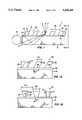
- FIG. 1is an elevation view of one embodiment of the present invention in conjunction with a single input light source
- FIG. 1Ais an exploded view of the embodiment of FIG. 1;
- FIG. 1Bis an alternate view of the embodiment of FIG. 1;
- FIG. 2is an elevation view of the embodiment of FIG. 1 including an array of microlenses
- FIG. 2Ais an alternate view of the embodiment of FIG. 2; corresponding microlens;
- FIG. 3is a sectional view of a single microlens
- FIG. 3 Ais a plan view of one embodiment of a single microlens
- FIG. 4is an elevation view of an alternate embodiment of the present invention in conjunction with two input light sources
- FIG. 4Ais an exploded view of the embodiment of FIG. 4;
- FIG. 5is an elevation view of the embodiment of FIG. 4 including an array of microlenses
- FIG. 6is a exploded view of the embodiment of FIG. 5.
- FIG. 7is an alternate view of the embodiment in FIG. 5.
- FIGS. 1, 1A and 1BOne preferred embodiment of the present invention is shown in FIGS. 1, 1A and 1B.
- An illumination systemrepresented by the number 2
- a light generating means 14a waveguide 16 having a light accepting surface 17 and a transparent reflecting means 18 in contact with waveguide 16.
- Illustrative of useful light generating means 14are lasers, fluorescent tubes, light emitting diodes, incandescent lights, sunlight and the like.
- the waveguide 16is made from any transparent material such as glass or polymer.
- light generating means 14is in close proximity to waveguide 16, and reflecting means 18 is in contact with wave guide 16.
- the reflecting means 18comprises an optional adhesion promoting layer 26 and an array of microprisms 28.
- Lightreflects through waveguide 16 via TIR and enters each microprism 28 by way of light input surface 30, reflects off sidewalls 33, 35 and 37 and exits the microprism 28 through the light output surface 32 as a spatially directed light source.
- Waveguide 16is transparent to light within the wavelength range from about 400 to about 700 nm.
- the index of refraction of the waveguide 16may range from about 1.40 to about 1.65.
- the most preferred index of refractionis from about 1.45 to about 1.60.
- the waveguide 16may be made from any transparent solid material.
- Preferred materialsinclude transparent polymers, glass and fused silica. Desired characteristics of these materials include mechanical and optical stability at typical operation temperatures of the device. Most preferred materials are glass, acrylic, polycarbonate and polyester.
- Microprisms 28can be constructed from any transparent solid material.
- Preferred materialshave an index of refraction equal to or greater than waveguide 16.
- Preferred materialshave a refractive index between about 1.40 and about 1.65 and include polymethylmethacrylate, polycarbonate, polyester, poly(4-methyl pentene), polystyrene and polymers formed by photopolymerization of acrylate monomers.
- More preferred materialshave an index of refraction between abut 1.45 and about 1.60 and may include polymers formed by photopolymerization of acrylate monomer mixtures composed of urethane acrylates and methacrylates, ester acrylates and methacrylates, epoxy acrylates and methacrylates, (poly) ethylene glycol acrylates and methacrylates and vinyl containing organic monomers.
- Useful monomersinclude methyl methacrylate, n-butyl acrylate, 2-ethylhexyl acrylate, isodecyl acrylate, 2-hydroxyethyl acrylate, 2-hydroxypropyl acrylate, cyclohexyl acrylate, 1,4-butanediol diacrylate, ethoxylated bisphenol A diacrylate, neopentylglycol diacrylate, diethyleneglycol diacrylate, diethylene glycol dimethacrylate, 1,6-hexanediol diacrylate, trimethylolpropane triacrylate, pentaerythritol triacrylate and pentaerythritol tetra-acrylate.
- the most preferred materials for microprisms 28 formed by photolithographyare crosslinked polymers formed by photopolymerizing mixtures of ethoxylated bisphenol A diacrylate and trimethylolpropane triacrylate.
- the index of refraction of the most preferred materialsranges from about 1.53 to about 1.56.
- Other materials that can be used in alternate methods of manufacture, such as injection molding,include polycarbonate, acrylic and poly(4-methyl pentene).
- Microprisms 28are separated by interstitial regions 36.
- the index of refraction of interstitial regions 36must be less than the index of refraction of the microprism 28.
- Preferred materials for interstitial regionsinclude air, with an index of refraction of 1.00 and fluoropolymer materials with an index of refraction ranging from about 1.16 to about 1.40. The most preferred material is air.
- the optional adhesion promoting layer 26is an organic material that is light transmissive and that causes the microprisms 28, especially microprisms formed from polymers, as for example photocrosslinked acrylate monomer materials, to adhere strongly to the waveguide 16. Such materials are well known to those skilled in the art.
- the thickness of adhesion promoting layer 26is not critical and can vary widely. In the preferred embodiment of the invention, adhesion layer 26 is less than about 30 micrometers thick.
- the microprismsmay be arranged in any pattern on waveguide 16, such as in a square, rectangular or hexagonal pattern.
- the microprismshave a repeat distance 38 (FIG. 1 ) in the direction perpendicular to light accepting surface 17 and repeat distance 40 (FIG. 1B) in the direction parallel to light accepting surface 17.
- Repeat distances 38 and 40may be equal or unequal and may vary widely depending on the resolution and dimensions of the display.
- the repeat distances 38 and 40may vary across the surface of the waveguide 16 in order to compensate for a lowering of the light intensity inside waveguide 16 as the distance from light generating means 14 increases. This lowering of the light intensity is due to light removal by the other microprisms of the array.
- the microprisms 28are constructed to form a six-sided geometrical shape having a light input surface 30 parallel with a light output surface 32, wherein the light output surface 32 is equal to or larger in surface area than the light input surface 30.
- Microprism 28further comprises two pairs of oppositely disposed sidewalls 33, 34 and 35, 37. Sidewalls 33, 35 and 37 are effective in reflecting and redirecting the light which is propagating through waveguide 16.
- the intersection of sidewall 33 with waveguide 16, or adhesion layer 26 thereonforms a line that is perpendicular to the average direction of the light. For example, as shown in FIG.
- sidewall 33the intersection of sidewall 33 with adhesion layer 26 forms a line parallel to the light accepting surface 17 and is therefore perpendicular to the average direction of the light traveling through the waveguide 16.
- sidewall 34is shown as parallel to sidewall 33, the orientation of side 34 is not critical.
- each microprism 28is formed so that sidewall 33 forms a tilt angle ⁇ to the normal of the surface of waveguide 16.
- the desired values of tilt angle ⁇range from about 15 degrees to about 50 degrees. More preferred values for tilt angle ⁇ range from about 20 degrees to about 40 degrees.
- tilt angle ⁇determines at which angle with respect to the normal of the light output surface the spatially directed light will emerge.
- sidewalls 35 and 37also form a tilt angle ⁇ to the normal of the surface of waveguide 16.
- the desired values of tilt angle ⁇range from about 0 degrees to about 25 degrees. More preferred values for tilt angle ⁇ range from about 2 degrees to about 15 degrees.
- the tilt angles ⁇ associated with sidewalls 35 and 37are equal, but equal angles are not necessary.
- the height of microprism 28has dimension 50 as shown in FIG. 1A. Height 50 may vary widely depending on the dimensions and resolution of the display. That is, smaller displays, such as laptop computer displays and avionics displays would have greatly reduced dimensions versus larger displays such as large screen, flat-panel televisions.
- the length of microprism 28has dimensions 52 and 53.
- Length 52corresponds to the light input surface 30 and length 53 corresponds to the light output surface 32.
- Length 53can be equal to or greater than length 52.
- Lengths 52 and 53may vary widely depending on the dimensions and resolution of the display.
- the length 52may vary across the surface of the light transmitting means 16 in order to compensate for a lowering of the light intensity inside waveguide 16 as the distance from light generating means 14 increases. That is, microprisms 28 that are closer to light generating means 14 may have a smaller dimension 52 as compared to microprisms farther from light generating means 14. This lowering of the light intensity is due to light removal by the other microprisms of the array.
- the maximum value for lengths 52 and 53is less than the repeat distance 38 of FIG. 1.
- Microprism 28has width dimensions 54 and 55 (FIG. 1B), where width 54 corresponds to the light input surface 30 and width 55 corresponds to the light output surface 32. Widths 54 and 55 may vary widely depending on the dimensions and resolution of the display and are a function of tilt angle ⁇ and height 50. In addition, the width 54 may vary across the surface of the light transmitting means 16 in order to compensate for a lowering of the light intensity inside waveguide 16 as the distance from light generating means 14 increases. The maximum value for widths 54 and 55 is less than the repeat distance 40. It is desireable that length dimension 52 be larger than width dimension 54. It is preferred that the ratio of length 52 to width 54 be in the range of 1.2:1 to 5:1. It is more preferred that the ratio be in the range of 1.5:1 to 3:1.
- reflecting means 18further comprises an array of microlenses 80 as shown in FIGS. 2 and 2A.
- the microlenses 80are disposed in close proximity to the microprisms 28. If the microlenses 80 are fabricated by photopolymerization, they are preferably made from the same monomers as those previously disclosed for the microprisms 28 and have a index of refraction equal to or substantially equal to the index of refraction of the microprisms 28. However, any transparent material may be used, as for example, those materials previously discussed.
- the center-to-center distance between microlensesdirectly correlates to the repeat distances 38 and 40 of the microprisms 28. That is, for every microprism 28 there exists a corresponding microlens 80 that aligns with the output surface 32 of each microprism 28.
- a spacer 82separates the microlenses 80 and the microprisms 28.
- the thickness of spacer 82is optimized to cause light from microprisms 28 to be collimated by microlenses 80.
- Spacer 82may be made from any transparent material. Preferred materials include transparent polymers, glass and fused silica. Preferably spacer 82 has an index of refraction equal to or substantially equal to the index of refraction of the microprisms 28 and the microlenses 80. Desired characteristics of these materials include mechanical and optical stability at typical operation temperatures of the device. Most preferred materials are glass, acrylic, polycarbonate and polyester.
- a single microlens 80is shown in FIG. 3.
- the microlenscan be either a spherical lens or an aspherical lens or an astigmatic lens.
- the footprint of a microlens 80is not necessarily circular, but can be rectangular in shape, as shown in FIG. 3A, having a length 86 and width 87 that are respectively equal in length with repeat distances 38 and 40.
- microlens 80is a spherical lens
- the lenswill have one curved surface having a radius of curvature 84.
- the radius of curvaturecan vary widely depending on the repeat distances 38 and 40 of the corresponding microprism array.
- the f-number of microlens 80should be relatively small.
- the f-number values for microlens 80can range from about 0.5 to about 4.0. More preferred values for the f-number range from about 0.6 to about 3.0.
- FIGS. 4 and 4AAnother alternate embodiment of the invention is shown in FIGS. 4 and 4A.
- Two light generating means 14 and 14Aare positioned adjacent to two oppositely disposed light accepting surfaces 17 and 17A of the waveguide 16.
- An array of microprisms 90are attached to the waveguide 16 in a similar manner disclosed above.
- the microprisms 90comprise a light input surface 92 parallel to a light output surface 94 wherein the light output surface 94 is larger in surface area than the light input surface 92.
- Microprism 90also comprises two pairs of oppositely disposed tilted sidewalls 96 and 98 and 97 and 99.
- Sidewalls 96 and 98are each formed at the angle ⁇ to the normal of the surface of waveguide 16.
- the tilt angles ⁇ associated with sidewalls 96 and 98are equal, but equal angles are not necessary.
- the intersection of each tilted sidewall 96 and 98 with the waveguide 16, or adhesion layer 26 thereon,is parallel to the oppositely disposed light accepting surfaces 17 and 17A, and therefore, perpendicular to the average direction of the light traveling through the waveguide 16.
- sidewalls 97 and 99are each formed at the angle ⁇ to the normal of the surface of waveguide 16.
- the tilt angles ⁇ associated with sidewalls 97 and 99are equal, but equal angles are not necessary.
- the intersection of each tilted sidewall 97 and 99 with the waveguide 16 or adhesion layer 26 thereon,is perpendicular to the oppositely disposed light accepting surfaces 17 and 17A, and therefore, parallel to the average direction of the light traveling through the waveguide 16.
- the height of microprism 90has dimension 110 and is similar to height 50 of microprism 28.
- the length of microprism waveguide 90has dimensions 120 and 122 where dimension 122 is less than dimension 120. Both lengths 120 and 122 are a function of tilt angle ⁇ and height 110. Lengths 120 and 122 may vary widely depending on the dimensions and resolution of the display. In addition, the lengths 120 and 122 may vary across the surface of the light transmitting means 16 in order to compensate for a lowering of the light intensity inside waveguide 16 as the distance from light generating means 14 and 14A increases. The maximum value for the length 120 is less than the repeat distance 138.
- the width of microprism 28has dimensions 130 and 132 as shown in FIG. 4A.
- Dimension 132is less than or equal to dimension 130. Both widths 130 and 132 are a function of tilt angle ⁇ and height 110. Widths 130 and 132 may vary widely depending on the factors discussed above for lengths 120 and 122.
- the maximum value for the width 130is less than the repeat distance 140. It is desireable that length dimension 122 be larger than width dimension 132. It is preferred that the ratio of length 122 to width 132 be in the range of 1.2:1 to 5:1. It is more preferred that the ratio be in the range of 1.5:1 to 3:1.
- FIGS. 5 through 7An still further alternate embodiment of the invention disclosed in FIGS. 5 through 7 comprises an array of microlenses 80 disposed in close proximity to microprisms 90.
- a spacer 82separates the microlenses 80 from microprisms 90 as previously disclosed.
- the lightemerges from each microprism 90 as a spatially directed light source and inputs into one or more microlenses.
- the light sourceis directed to two microlenses.
- the spatially directed light source emanating from the microprisms 90is collimated by the microlenses 80 to provide a substantially collimated light pattern.
- the center-to-center distance between microlensesdirectly correlates to the repeat distances 138 and 140 of the microprisms 90.
- the length 86(FIG.
- each microlens 80aligns with respect to the microprism array so that equal distances overlap adjacent microprisms as shown in FIGS. 5 and 6.
- the width 87 of each microlensaligns with respect to a single microlens as shown in FIG. 7.
- Arrays of microprisms 28 and 90 and microlenses 80can be manufactured by any number of techniques such as molding, including injection and compression molding, casting, including hot roller pressing casting, photopolymerization within a mold and photopolymerization processes which do not employ a mold.
- a preferred manufacturing techniquewould be one that allows the reflecting means 18 which comprises an array of microprisms 28 or 90, an array of microlenses 80 and a spacer 82 to be manufactured as a single integrated unit.
- An advantage of this techniquewould be the elimination of alignment errors between the array of microprisms and microlenses if the arrays were manufactured separately and then attached in the relationship described above.
Landscapes
- Physics & Mathematics (AREA)
- General Physics & Mathematics (AREA)
- Optics & Photonics (AREA)
- Engineering & Computer Science (AREA)
- General Engineering & Computer Science (AREA)
- Light Guides In General And Applications Therefor (AREA)
- Optical Couplings Of Light Guides (AREA)
- Planar Illumination Modules (AREA)
- Optical Elements Other Than Lenses (AREA)
Abstract
Description
Claims (26)
Priority Applications (20)
| Application Number | Priority Date | Filing Date | Title |
|---|---|---|---|
| US08/242,525US5428468A (en) | 1993-11-05 | 1994-05-13 | Illumination system employing an array of microprisms |
| US08/368,286US5521725A (en) | 1993-11-05 | 1995-01-03 | Illumination system employing an array of microprisms |
| US08/376,709US5555329A (en) | 1993-11-05 | 1995-01-23 | Light directing optical structure |
| US08/394,098US5555109A (en) | 1993-11-05 | 1995-02-24 | Illumination system employing an array of microprisms |
| CN95193053ACN1095056C (en) | 1994-05-13 | 1995-04-07 | Illumination system employing an array of microprisms |
| KR1019960706183AKR100373312B1 (en) | 1994-05-13 | 1995-04-07 | Lighting system using microprism array |
| PCT/US1995/004285WO1995031672A1 (en) | 1994-05-13 | 1995-04-07 | Illumination system employing an array of microprisms |
| JP52963995AJP3488467B2 (en) | 1994-05-13 | 1995-04-07 | Illumination system using an array of microprisms |
| AU22802/95AAU2280295A (en) | 1994-05-13 | 1995-04-07 | Illumination system employing an array of microprisms |
| MX9605117AMX9605117A (en) | 1994-05-13 | 1995-04-07 | Illumination system employing an array of microprisms. |
| DE69507456TDE69507456T2 (en) | 1994-05-13 | 1995-04-07 | LIGHTING GRID USING LIGHTING SYSTEM |
| CA002190122ACA2190122C (en) | 1994-05-13 | 1995-04-07 | Illumination system employing an array of microprisms |
| EP95916225AEP0749550B1 (en) | 1994-05-13 | 1995-04-07 | Illumination system employing an array of microprisms |
| MYPI95000972AMY113843A (en) | 1994-05-13 | 1995-04-14 | Illumination system employing an array of microprisms |
| IN679DE1995IN190745B (en) | 1994-05-13 | 1995-04-17 | |
| TW084104849ATW301717B (en) | 1994-05-13 | 1995-05-16 | |
| US08/691,073US5761355A (en) | 1993-11-05 | 1996-08-01 | Light directing optical structure |
| US08/691,072US5739931A (en) | 1994-01-11 | 1996-08-01 | Illumination system employing an array of microprisms |
| US08/782,133US5748828A (en) | 1993-11-10 | 1997-01-13 | Color separating backlight |
| US08/832,324US6129439A (en) | 1993-11-05 | 1997-03-26 | Illumination system employing an array of multi-faceted microprisms |
Applications Claiming Priority (2)
| Application Number | Priority Date | Filing Date | Title |
|---|---|---|---|
| US08/149,219US5396350A (en) | 1993-11-05 | 1993-11-05 | Backlighting apparatus employing an array of microprisms |
| US08/242,525US5428468A (en) | 1993-11-05 | 1994-05-13 | Illumination system employing an array of microprisms |
Related Parent Applications (2)
| Application Number | Title | Priority Date | Filing Date |
|---|---|---|---|
| US08/149,219Continuation-In-PartUS5396350A (en) | 1993-11-05 | 1993-11-05 | Backlighting apparatus employing an array of microprisms |
| US14921994AContinuation-In-Part | 1994-01-11 | 1994-01-11 |
Related Child Applications (4)
| Application Number | Title | Priority Date | Filing Date |
|---|---|---|---|
| US32136894AContinuation-In-Part | 1993-11-05 | 1994-10-11 | |
| US08/368,286Continuation-In-PartUS5521725A (en) | 1993-11-05 | 1995-01-03 | Illumination system employing an array of microprisms |
| US08/376,709Continuation-In-PartUS5555329A (en) | 1993-11-05 | 1995-01-23 | Light directing optical structure |
| US08/394,098ContinuationUS5555109A (en) | 1993-11-05 | 1995-02-24 | Illumination system employing an array of microprisms |
Publications (1)
| Publication Number | Publication Date |
|---|---|
| US5428468Atrue US5428468A (en) | 1995-06-27 |
Family
ID=22915121
Family Applications (3)
| Application Number | Title | Priority Date | Filing Date |
|---|---|---|---|
| US08/242,525Expired - LifetimeUS5428468A (en) | 1993-11-05 | 1994-05-13 | Illumination system employing an array of microprisms |
| US08/394,098Expired - LifetimeUS5555109A (en) | 1993-11-05 | 1995-02-24 | Illumination system employing an array of microprisms |
| US08/691,072Expired - LifetimeUS5739931A (en) | 1994-01-11 | 1996-08-01 | Illumination system employing an array of microprisms |
Family Applications After (2)
| Application Number | Title | Priority Date | Filing Date |
|---|---|---|---|
| US08/394,098Expired - LifetimeUS5555109A (en) | 1993-11-05 | 1995-02-24 | Illumination system employing an array of microprisms |
| US08/691,072Expired - LifetimeUS5739931A (en) | 1994-01-11 | 1996-08-01 | Illumination system employing an array of microprisms |
Country Status (13)
| Country | Link |
|---|---|
| US (3) | US5428468A (en) |
| EP (1) | EP0749550B1 (en) |
| JP (1) | JP3488467B2 (en) |
| KR (1) | KR100373312B1 (en) |
| CN (1) | CN1095056C (en) |
| AU (1) | AU2280295A (en) |
| CA (1) | CA2190122C (en) |
| DE (1) | DE69507456T2 (en) |
| IN (1) | IN190745B (en) |
| MX (1) | MX9605117A (en) |
| MY (1) | MY113843A (en) |
| TW (1) | TW301717B (en) |
| WO (1) | WO1995031672A1 (en) |
Cited By (101)
| Publication number | Priority date | Publication date | Assignee | Title |
|---|---|---|---|---|
| US5543958A (en)* | 1994-12-21 | 1996-08-06 | Motorola | Integrated electro-optic package for reflective spatial light modulators |
| US5554845A (en)* | 1994-11-14 | 1996-09-10 | Santa Barbara Research Center | Method and apparatus to effectively eliminate optical interference structure in detector response |
| WO1997016765A1 (en)* | 1995-11-02 | 1997-05-09 | Philips Electronics N.V. | Picture display device |
| WO1997026584A1 (en)* | 1996-01-16 | 1997-07-24 | Alliedsignal Inc. | A color separating backlight |
| WO1997030373A1 (en)* | 1996-02-14 | 1997-08-21 | Physical Optics Corporation | Apparatus for lcd backlighting |
| US5748828A (en)* | 1993-11-10 | 1998-05-05 | Alliedsignal Inc. | Color separating backlight |
| US5838403A (en)* | 1996-02-14 | 1998-11-17 | Physical Optics Corporation | Liquid crystal display system with internally reflecting waveguide for backlighting and non-Lambertian diffusing |
| US5839823A (en)* | 1996-03-26 | 1998-11-24 | Alliedsignal Inc. | Back-coupled illumination system with light recycling |
| EP0886103A2 (en) | 1995-01-23 | 1998-12-23 | AlliedSignal Inc. | Light directing optical structure |
| WO1999045317A1 (en) | 1998-03-03 | 1999-09-10 | Alliedsignal Inc. | A lenticular illumination system |
| US5995690A (en)* | 1996-11-21 | 1999-11-30 | Minnesota Mining And Manufacturing Company | Front light extraction film for light guiding systems and method of manufacture |
| US6010747A (en)* | 1996-12-02 | 2000-01-04 | Alliedsignal Inc. | Process for making optical structures for diffusing light |
| US6049649A (en)* | 1996-03-28 | 2000-04-11 | Enplas Corporation | Surface light source device of side-light type |
| US6129439A (en)* | 1993-11-05 | 2000-10-10 | Alliedsignal Inc. | Illumination system employing an array of multi-faceted microprisms |
| US6144536A (en)* | 1997-02-13 | 2000-11-07 | Honeywell International Inc. | Illumination system with light recycling to enhance brightness |
| US6164789A (en)* | 1996-07-12 | 2000-12-26 | Honeywell International Inc. | Illumination sources and systems |
| US6185357B1 (en) | 1998-09-10 | 2001-02-06 | Honeywell International Inc. | Illumination system using edge-illuminated hollow waveguide and lenticular optical structures |
| WO2001053744A1 (en)* | 2000-01-18 | 2001-07-26 | Screen Technology Limited | Radiation source producing a collimated beam |
| US6306563B1 (en) | 1999-06-21 | 2001-10-23 | Corning Inc. | Optical devices made from radiation curable fluorinated compositions |
| US6305811B1 (en)* | 1998-09-25 | 2001-10-23 | Honeywell International Inc. | Illumination system having an array of linear prisms |
| US6347874B1 (en) | 2000-02-16 | 2002-02-19 | 3M Innovative Properties Company | Wedge light extractor with risers |
| US6362815B1 (en)* | 1998-04-09 | 2002-03-26 | Flat Panel Display Co. B.V. | Touch sensor display |
| US6424786B1 (en) | 1996-12-02 | 2002-07-23 | Honeywell International Inc. | Illumination assembly |
| WO2002081965A1 (en) | 2001-04-06 | 2002-10-17 | 3M Innovative Properties Company | Frontlit display |
| US6473220B1 (en) | 1998-01-22 | 2002-10-29 | Trivium Technologies, Inc. | Film having transmissive and reflective properties |
| US6528937B1 (en)* | 1999-02-24 | 2003-03-04 | Koninklijke Philips Electronics N.V. | Display device including a light guide with movable element for emitting visible light when excited by ultraviolet radiation |
| US6555288B1 (en) | 1999-06-21 | 2003-04-29 | Corning Incorporated | Optical devices made from radiation curable fluorinated compositions |
| US6576887B2 (en) | 2001-08-15 | 2003-06-10 | 3M Innovative Properties Company | Light guide for use with backlit display |
| US6597834B1 (en)* | 1998-03-13 | 2003-07-22 | 3M Innovative Properties Company | Optical fiber linear light source |
| US20030206256A1 (en)* | 2002-05-06 | 2003-11-06 | Drain Kieran F. | Display device with backlight |
| KR100431358B1 (en)* | 2001-11-29 | 2004-05-14 | 주식회사 테크자인 | Methods for making dispersion pattern on a light guiding panel |
| US6738051B2 (en) | 2001-04-06 | 2004-05-18 | 3M Innovative Properties Company | Frontlit illuminated touch panel |
| US20050018103A1 (en)* | 2003-05-20 | 2005-01-27 | Lubart Neil D. | Devices for use in non-emissive displays |
| US20050072032A1 (en)* | 1995-06-27 | 2005-04-07 | Mccollum Timothy A. | Light emitting panel assemblies |
| EP1555567A1 (en)* | 1996-01-16 | 2005-07-20 | Honeywell International Inc. | A color separating backlight |
| US20050259198A1 (en)* | 2002-03-26 | 2005-11-24 | Trivium Technologies, Inc. | Light collimating device |
| US20050270798A1 (en)* | 2004-06-03 | 2005-12-08 | Eastman Kodak Company | Brightness enhancement film using a linear arrangement of light concentrators |
| US20060103779A1 (en)* | 2004-11-18 | 2006-05-18 | Hiroyuki Amemiya | View angle controlling sheet and liquid crystal display apparatus using the same |
| US20060104084A1 (en)* | 2004-11-18 | 2006-05-18 | Hiroyuki Amemiya | View angle controlling sheet and liquid crystal display apparatus using the same |
| US20060221634A1 (en)* | 2005-03-29 | 2006-10-05 | Konica Minolta Holdings, Inc. | Surface light emitter and display apparatus |
| US20060233486A1 (en)* | 2002-12-31 | 2006-10-19 | Daniele Faccio | Integrated optical add/drop device having switching function |
| US20070030413A1 (en)* | 2005-08-03 | 2007-02-08 | Raymond Lippmann | Liquid crystal display with differently-colored localized display areas |
| US20070035843A1 (en)* | 2006-01-13 | 2007-02-15 | Optical Research Associates | Optical apparatus with flipped compound prism structures |
| US20070058391A1 (en)* | 2005-09-14 | 2007-03-15 | Wilson Randall H | Light extraction layer |
| US20070086086A1 (en)* | 2006-01-13 | 2007-04-19 | Optical Research Associates | Light enhancing structures with three or more arrays of elongate features |
| US20070086207A1 (en)* | 2006-01-13 | 2007-04-19 | Optical Research Associates | Display systems including light enhancing structures with arrays of elongate features |
| US20070091616A1 (en)* | 2006-01-13 | 2007-04-26 | Optical Research Associates | Light enhancing structures with multiple arrays of elongate features of varying characteristics |
| US20070147763A1 (en)* | 2003-06-10 | 2007-06-28 | Abu-Ageel Nayef M | Compact Light Collection System and Method |
| US20070172171A1 (en)* | 2006-01-24 | 2007-07-26 | Uni-Pixel Displays, Inc. | Optical microstructures for light extraction and control |
| US20070203267A1 (en)* | 2006-02-28 | 2007-08-30 | 3M Innovative Properties Company | Optical display with fluted optical plate |
| US20070206193A1 (en)* | 2004-01-13 | 2007-09-06 | Glucon, Inc. | Photoacoustic Sensor |
| US20070230213A1 (en)* | 2006-03-28 | 2007-10-04 | Samsung Electronics Co., Ltd. | Backlight having all-in-one type light guide plate and method of manufacturing all-in-one type light guide plate |
| US20070230218A1 (en)* | 2006-03-29 | 2007-10-04 | 3M Innovative Properties Company | Optical film assemblies and methods of making same |
| US20070236960A1 (en)* | 2006-03-29 | 2007-10-11 | Anderson Susan E | Edge-lit optical display with fluted optical plate |
| US20070236413A1 (en)* | 2006-03-29 | 2007-10-11 | 3M Innovative Properties Company | Fluted optical plate with internal light sources and systems using same |
| US20070242334A1 (en)* | 2006-01-24 | 2007-10-18 | Uni-Pixel Displays, Inc. | Corner-Cube Retroreflectors for Displays |
| CN100406995C (en)* | 2004-02-13 | 2008-07-30 | 西铁城电子股份有限公司 | Backlight system |
| US20080253132A1 (en)* | 2006-03-13 | 2008-10-16 | Tetsuo Urabe | Display unit |
| US20090067784A1 (en)* | 2007-09-10 | 2009-03-12 | Banyan Energy, Inc. | Compact optics for concentration, aggregation and illumination of light energy |
| US20090064993A1 (en)* | 2007-09-10 | 2009-03-12 | Banyan Energy, Inc. | Solar energy concentrator |
| WO2007149128A3 (en)* | 2006-06-16 | 2009-04-09 | Brilliant Film Llc | Method for making collimating or transflecting film having a reflecting layer |
| US20090235985A1 (en)* | 2008-02-27 | 2009-09-24 | Trivium Technologies, Inc. | Concentrators for solar power generating systems |
| US7595934B2 (en) | 2002-03-26 | 2009-09-29 | Brilliant Film Llc | Integrated sub-assembly having a light collimating or transflecting device |
| US20090286020A1 (en)* | 2005-05-12 | 2009-11-19 | Tokyo Ohka Kogyo Co., Ltd. | Photosensitive dry film for production of three-dimensional micro-molded product, and photosensitive resin composition |
| US20090302204A1 (en)* | 2005-08-26 | 2009-12-10 | Mitsuru Saito | Light irradiation apparatus and optical member |
| US20100067254A1 (en)* | 2006-11-24 | 2010-03-18 | Fuji Polymer Industries Co., Ltd. | Light guide sheet and electronic equipment utilizing the same |
| US7866871B2 (en) | 2006-01-13 | 2011-01-11 | Avery Dennison Corporation | Light enhancing structures with a plurality of arrays of elongate features |
| US8412010B2 (en) | 2007-09-10 | 2013-04-02 | Banyan Energy, Inc. | Compact optics for concentration and illumination systems |
| EP2618045A1 (en)* | 2012-01-20 | 2013-07-24 | Automotive Lighting Reutlingen GmbH | Lighting device for a motor vehicle |
| US8705914B2 (en) | 2007-09-10 | 2014-04-22 | Banyan Energy, Inc. | Redirecting optics for concentration and illumination systems |
| US20140355302A1 (en)* | 2013-03-15 | 2014-12-04 | Cree, Inc. | Outdoor and/or Enclosed Structure LED Luminaire for General Illumination Applications, Such as Parking Lots and Structures |
| EP2767754A3 (en)* | 2007-05-01 | 2015-02-18 | Morgan Solar Inc. | Illumination device |
| US20150109820A1 (en)* | 2013-03-15 | 2015-04-23 | Cree, Inc. | Outdoor and/or Enclosed Structure LED Luminaire |
| EP2894396A1 (en) | 2014-01-09 | 2015-07-15 | Cree, Inc. | Extraction film for optical waveguide and method of producing same |
| US9291320B2 (en) | 2013-01-30 | 2016-03-22 | Cree, Inc. | Consolidated troffer |
| US9366396B2 (en) | 2013-01-30 | 2016-06-14 | Cree, Inc. | Optical waveguide and lamp including same |
| US9366799B2 (en) | 2013-03-15 | 2016-06-14 | Cree, Inc. | Optical waveguide bodies and luminaires utilizing same |
| US9389367B2 (en) | 2013-01-30 | 2016-07-12 | Cree, Inc. | Optical waveguide and luminaire incorporating same |
| US9442243B2 (en) | 2013-01-30 | 2016-09-13 | Cree, Inc. | Waveguide bodies including redirection features and methods of producing same |
| US9625638B2 (en) | 2013-03-15 | 2017-04-18 | Cree, Inc. | Optical waveguide body |
| US9645303B2 (en) | 2013-03-15 | 2017-05-09 | Cree, Inc. | Luminaires utilizing edge coupling |
| US9690029B2 (en) | 2013-01-30 | 2017-06-27 | Cree, Inc. | Optical waveguides and luminaires incorporating same |
| US20170192152A1 (en)* | 2016-01-06 | 2017-07-06 | Samsung Electronics Co., Ltd. | Backlight unit and display device including the same |
| US9798072B2 (en) | 2013-03-15 | 2017-10-24 | Cree, Inc. | Optical element and method of forming an optical element |
| US9803833B2 (en) | 2013-12-03 | 2017-10-31 | X Development Llc | Multi-aperture illumination layer for tileable display |
| US9869432B2 (en) | 2013-01-30 | 2018-01-16 | Cree, Inc. | Luminaires using waveguide bodies and optical elements |
| US9920901B2 (en) | 2013-03-15 | 2018-03-20 | Cree, Inc. | LED lensing arrangement |
| US9946008B2 (en) | 2015-01-20 | 2018-04-17 | Panasonic Intellectual Property Management Co., Ltd. | Indication lighting device and vacuum cleaner including the same |
| CN107923580A (en)* | 2015-09-02 | 2018-04-17 | 亮锐控股有限公司 | LED modules and lighting module |
| US10135033B2 (en) | 2016-10-20 | 2018-11-20 | Corning Incorporated | Directional light extraction for organic light emitting diode (OLED) illumination devices |
| US10209429B2 (en) | 2013-03-15 | 2019-02-19 | Cree, Inc. | Luminaire with selectable luminous intensity pattern |
| CN110058450A (en)* | 2018-01-19 | 2019-07-26 | 夏普株式会社 | Lighting device and display device |
| CN110058451A (en)* | 2018-01-19 | 2019-07-26 | 夏普株式会社 | Lighting device and display device |
| US10416377B2 (en) | 2016-05-06 | 2019-09-17 | Cree, Inc. | Luminaire with controllable light emission |
| US10436970B2 (en) | 2013-03-15 | 2019-10-08 | Ideal Industries Lighting Llc | Shaped optical waveguide bodies |
| US10739513B2 (en) | 2018-08-31 | 2020-08-11 | RAB Lighting Inc. | Apparatuses and methods for efficiently directing light toward and away from a mounting surface |
| US10801679B2 (en) | 2018-10-08 | 2020-10-13 | RAB Lighting Inc. | Apparatuses and methods for assembling luminaires |
| US11112083B2 (en) | 2013-03-15 | 2021-09-07 | Ideal Industries Lighting Llc | Optic member for an LED light fixture |
| US20230161127A1 (en)* | 2020-04-15 | 2023-05-25 | CommScope Connectivity Belgium BV | Device and method for sealing cables in telecommunications enclosures |
| US11719882B2 (en) | 2016-05-06 | 2023-08-08 | Ideal Industries Lighting Llc | Waveguide-based light sources with dynamic beam shaping |
| US12372219B2 (en)* | 2014-05-30 | 2025-07-29 | Cree Lighting Usa Llc | LED luminaire with a cavity, finned interior, and a curved outer wall extending from a surface on which the light source is mounted |
Families Citing this family (59)
| Publication number | Priority date | Publication date | Assignee | Title |
|---|---|---|---|---|
| US5428468A (en)* | 1993-11-05 | 1995-06-27 | Alliedsignal Inc. | Illumination system employing an array of microprisms |
| US5719649A (en)* | 1994-06-08 | 1998-02-17 | Kabushiki Kaisha Toshiba | Light guide and liquid crystal display device using it |
| JP3438365B2 (en)* | 1994-11-29 | 2003-08-18 | ソニー株式会社 | Composite optical device and method of manufacturing the same |
| JP3924804B2 (en)* | 1996-04-09 | 2007-06-06 | カシオ計算機株式会社 | Light guiding device, manufacturing method thereof, and light source structure using the same |
| US5914760A (en)* | 1996-06-21 | 1999-06-22 | Casio Computer Co., Ltd. | Surface light source device and liquid crystal display device using the same |
| EP0846915B1 (en)* | 1996-12-04 | 2003-08-27 | Siteco Beleuchtungstechnik GmbH | Inner room light |
| FR2766257B1 (en)* | 1997-07-21 | 1999-10-08 | Valeo Vision | LIGHT DUCT LIGHTING MODULE FOR A MOTOR VEHICLE |
| GB2328312B (en)* | 1997-08-14 | 1999-08-04 | John Quentin Phillipps | Mirror controlled display device |
| JP3808992B2 (en)* | 1997-11-21 | 2006-08-16 | 三菱電機株式会社 | LCD panel module |
| JPH11194339A (en)* | 1998-01-07 | 1999-07-21 | Seiko Epson Corp | Liquid crystal devices and electronic equipment |
| US6195196B1 (en)* | 1998-03-13 | 2001-02-27 | Fuji Photo Film Co., Ltd. | Array-type exposing device and flat type display incorporating light modulator and driving method thereof |
| DE19835922A1 (en) | 1998-08-07 | 2000-02-10 | Siteco Beleuchtungstech Gmbh | Optical display device |
| US6169594B1 (en) | 1998-08-24 | 2001-01-02 | Physical Optics Corporation | Beam deflector and scanner |
| JP4111363B2 (en)* | 1998-12-10 | 2008-07-02 | 株式会社エンプラス | Light guide plate, side light type surface light source device, and liquid crystal display device |
| DE69941180D1 (en) | 1999-05-07 | 2009-09-10 | Asulab Sa | Device for oriented surface illumination by a microprismatic conductor |
| TW514707B (en)* | 1999-05-07 | 2002-12-21 | Asulab Sa | Device for the oriented illumination of a surface by a microprism guide |
| ATE350620T1 (en) | 1999-05-25 | 2007-01-15 | Siteco Beleuchtungstech Gmbh | LUMINAIRE WITH WIDE BEAM LIGHT DISTRIBUTION |
| EP1055870A1 (en) | 1999-05-25 | 2000-11-29 | Siteco Beleuchtungstechnik GmbH | Indoor luminaire with refractive glare limiter |
| EP1055865B2 (en) | 1999-05-25 | 2014-10-29 | Siteco Beleuchtungstechnik GmbH | Light fixture of the hanging type with indirect lighting |
| EP1065435A1 (en) | 1999-05-28 | 2001-01-03 | Siteco Beleuchtungstechnik GmbH | Ceiling lamp |
| EP1058177A1 (en)* | 1999-06-04 | 2000-12-06 | Alps Electric Co., Ltd. | Input device for game machine |
| JP2001051272A (en)* | 1999-08-11 | 2001-02-23 | Semiconductor Energy Lab Co Ltd | Front light and electronic appliance |
| US6195016B1 (en) | 1999-08-27 | 2001-02-27 | Advance Display Technologies, Inc. | Fiber optic display system with enhanced light efficiency |
| US6356391B1 (en) | 1999-10-08 | 2002-03-12 | 3M Innovative Properties Company | Optical film with variable angle prisms |
| DE19956916A1 (en)* | 1999-11-26 | 2001-06-07 | Spectral Ges Fuer Lichttechnik | Lighting system for rooms |
| DE10011304B4 (en) | 2000-03-09 | 2011-05-05 | Siteco Beleuchtungstechnik Gmbh | Luminaire with inhomogeneous light emission |
| DE10011516A1 (en)* | 2000-03-09 | 2001-09-20 | Siteco Beleuchtungstech Gmbh | Lighting system |
| TW516164B (en)* | 2000-04-21 | 2003-01-01 | Semiconductor Energy Lab | Self-light emitting device and electrical appliance using the same |
| US6767106B2 (en)* | 2000-05-08 | 2004-07-27 | Lexalite International Corporation | Edge-lit luminaire having prismatic optical control |
| US6697042B1 (en) | 2000-11-27 | 2004-02-24 | Rainbow Displays, Inc. | Backlight assembly for collimated illumination |
| CN1213335C (en) | 2001-02-19 | 2005-08-03 | 皇家菲利浦电子有限公司 | Illumination system and display device |
| US6697552B2 (en) | 2001-02-23 | 2004-02-24 | Lightwave Microsystems Corporation | Dendritic taper for an integrated optical wavelength router |
| US6844970B2 (en)* | 2001-05-03 | 2005-01-18 | General Electric Company | Projection television set, screens, and method |
| ATE516467T1 (en) | 2002-10-15 | 2011-07-15 | Siteco Beleuchtungstech Gmbh | REFLECTOR WITH A STRUCTURED SURFACE, AND LAMP AND SECONDARY LIGHTING SYSTEM WITH SUCH A REFLECTOR |
| GB0224800D0 (en)* | 2002-10-24 | 2002-12-04 | Microsharp Corp Ltd | Apparatus for producing approximately collimated light and method of curing a photopolymerisable layer using the apparatus |
| US7286280B2 (en)* | 2004-05-07 | 2007-10-23 | The University Of British Columbia | Brightness enhancement film for backlit image displays |
| JP2005353599A (en)* | 2004-06-11 | 2005-12-22 | Valeo Vision | Vehicle lighting or signaling system with light guide |
| JP3826145B2 (en)* | 2004-07-16 | 2006-09-27 | 株式会社クラレ | Condensing film, liquid crystal panel and backlight, and method for producing condensing film |
| WO2007020820A1 (en)* | 2005-08-12 | 2007-02-22 | Sharp Kabushiki Kaisha | Backlight unit and liquid crystal display device |
| EP1952056B1 (en)* | 2005-11-14 | 2014-01-22 | Koninklijke Philips N.V. | Thin and efficient light collimating device |
| US7139125B1 (en)* | 2005-12-13 | 2006-11-21 | Eastman Kodak Company | Polarizing turning film using total internal reflection |
| US7452120B2 (en)* | 2006-03-24 | 2008-11-18 | Rohm And Haas Denmark Finance A/S | Illumination apparatus and film |
| JP4274239B2 (en) | 2006-12-27 | 2009-06-03 | ソニー株式会社 | Planar light source device, display device, and planar illumination method |
| US20080285304A1 (en)* | 2007-05-18 | 2008-11-20 | Rankin Jr Charles M | Light extraction film system |
| US8177406B2 (en)* | 2007-12-19 | 2012-05-15 | Edward Pakhchyan | Display including waveguide, micro-prisms and micro-mirrors |
| JP5275441B2 (en)* | 2009-02-17 | 2013-08-28 | シャープ株式会社 | Light guide, surface light source device, and liquid crystal display device |
| EP2284594B1 (en)* | 2009-08-13 | 2013-11-27 | Edward Pakhchyan | Display including waveguide, micro-prisms and micro-mechanical light modulators |
| JP5970198B2 (en)* | 2011-02-14 | 2016-08-17 | 株式会社半導体エネルギー研究所 | Lighting device |
| TWI484250B (en)* | 2011-04-08 | 2015-05-11 | Front light module | |
| WO2012148928A2 (en) | 2011-04-26 | 2012-11-01 | Inteled Corporation | Product lighting refrigeration door |
| JP6228110B2 (en)* | 2011-04-28 | 2017-11-08 | エル イー エス エス・リミテッド | Waveguide device for illumination system |
| US20140140091A1 (en) | 2012-11-20 | 2014-05-22 | Sergiy Victorovich Vasylyev | Waveguide illumination system |
| TWI487983B (en)* | 2012-05-03 | 2015-06-11 | Univ Nat Chiao Tung | Optical film and backlight module using the same |
| DE102012215640A1 (en) | 2012-09-04 | 2014-03-06 | Zumtobel Lighting Gmbh | Light guide unit for a lighting system |
| US9952372B2 (en)* | 2013-03-15 | 2018-04-24 | Cree, Inc. | Luminaire utilizing waveguide |
| US10222533B2 (en)* | 2014-04-09 | 2019-03-05 | Kookmin University Industry Academy Cooperation Foundation | Backlight unit and display device comprising same |
| AT16410U1 (en)* | 2015-10-09 | 2019-08-15 | Zumtobel Lighting Gmbh | Arrangement for surface light emission |
| CN107065063A (en)* | 2017-06-15 | 2017-08-18 | 青岛海信电器股份有限公司 | A kind of liquid crystal display device |
| JP7539475B2 (en)* | 2020-01-20 | 2024-08-23 | レイア、インコーポレイテッド | Micro-slit scattering element based backlight, multi-view display and method for providing light exclusion zones - Patents.com |
Citations (38)
| Publication number | Priority date | Publication date | Assignee | Title |
|---|---|---|---|---|
| US3863246A (en)* | 1973-07-09 | 1975-01-28 | Collins Radio Co | Backlighted display apparatus for preventing direct viewing of light sources |
| US4043636A (en)* | 1974-12-23 | 1977-08-23 | Intel Corporation | Illumination-panel for liquid crystal display of similar device |
| US4330813A (en)* | 1979-12-07 | 1982-05-18 | Commissariat A L'energie Atomique | Illuminating device for large screen |
| US4365869A (en)* | 1979-02-13 | 1982-12-28 | Thomson-Csf | Large-screen visualization device |
| US4686519A (en)* | 1984-01-10 | 1987-08-11 | Citizen Watch Co. Ltd. | Multicolor picture display device |
| US4726662A (en)* | 1985-09-24 | 1988-02-23 | Talig Corporation | Display including a prismatic lens system or a prismatic reflective system |
| US4799137A (en)* | 1987-03-24 | 1989-01-17 | Minnesota Mining And Manufacturing Company | Reflective film |
| US4874228A (en)* | 1987-03-24 | 1989-10-17 | Minnesota Mining And Manufacturing Company | Back-lit display |
| US5050946A (en)* | 1990-09-27 | 1991-09-24 | Compaq Computer Corporation | Faceted light pipe |
| US5099343A (en)* | 1989-05-25 | 1992-03-24 | Hughes Aircraft Company | Edge-illuminated liquid crystal display devices |
| US5101279A (en)* | 1989-12-14 | 1992-03-31 | Canon Kabushiki Kaisha | Liquid crystal display apparatus having lenticular elements oriented in relation to LC pixel aperture dimensions |
| US5126882A (en)* | 1987-11-12 | 1992-06-30 | Mitsubishi Rayon Co., Ltd. | Plane light source unit |
| US5128787A (en)* | 1990-12-07 | 1992-07-07 | At&T Bell Laboratories | Lcd display with multifaceted back reflector |
| US5128783A (en)* | 1990-01-31 | 1992-07-07 | Ois Optical Imaging Systems, Inc. | Diffusing/collimating lens array for a liquid crystal display |
| EP0500960A1 (en)* | 1990-09-12 | 1992-09-02 | Mitsubishi Rayon Co., Ltd. | Element of plane source of light |
| US5151801A (en)* | 1989-11-30 | 1992-09-29 | Pioneer Electronic Corporation | Liquid crystal display apparatus providing improved illumination via trucated prisms |
| US5161041A (en)* | 1990-04-26 | 1992-11-03 | Ois Optical Imaging Systems, Inc. | Lighting assembly for a backlit electronic display including an integral image splitting and collimating means |
| US5182663A (en)* | 1991-08-30 | 1993-01-26 | Raychem Corporation | Liquid crystal display having improved retroreflector |
| JPH0545505A (en)* | 1991-06-28 | 1993-02-23 | Nec Kansai Ltd | Plane light emission plate |
| JPH0560908A (en)* | 1990-12-17 | 1993-03-12 | Mitsubishi Rayon Co Ltd | Surface light source device and production therefor and dry film resist used therefor |
| JPH0589827A (en)* | 1991-09-26 | 1993-04-09 | Sony Corp | Photo-convergenece type back light |
| US5202950A (en)* | 1990-09-27 | 1993-04-13 | Compaq Computer Corporation | Backlighting system with faceted light pipes |
| US5206746A (en)* | 1990-07-12 | 1993-04-27 | Asahi Glass Company Ltd. | Transparent-scattering type optical device including a prism with a triangular longitudinal cross section |
| US5237641A (en)* | 1992-03-23 | 1993-08-17 | Nioptics Corporation | Tapered multilayer luminaire devices |
| US5253089A (en)* | 1991-11-07 | 1993-10-12 | Rohm Co., Ltd. | Backlighted liquid crystal display unit |
| US5253151A (en)* | 1991-09-30 | 1993-10-12 | Rockwell International Corporation | Luminaire for use in backlighting a liquid crystal display matrix |
| US5262928A (en)* | 1991-02-21 | 1993-11-16 | Tosoh Corporation | Back lighting device |
| US5262880A (en)* | 1990-04-26 | 1993-11-16 | Ois Optical Imaging Systems, Inc. | Night vision goggle compatible liquid crystal display device |
| US5267062A (en)* | 1991-08-26 | 1993-11-30 | Rockwell International Corporation | System for backlighting LCD matrices including luminescent dots each followed by and at the focal point of a lens |
| US5267063A (en)* | 1992-07-02 | 1993-11-30 | At&T Bell Laboratories | Gradient index mirror for providing a collimated beam for liquid crystal displays and the like |
| US5276538A (en)* | 1990-04-05 | 1994-01-04 | Matsushita Electric Industrial Co., Ltd. | Display device with micro lens array |
| WO1994000780A1 (en)* | 1992-06-22 | 1994-01-06 | Nioptics Corporation | Illumination system having an aspherical lens |
| US5278545A (en)* | 1992-06-11 | 1994-01-11 | Showa Hatsumei Kaisha, Ltd. | Backlit LCD display panels including sensible panels for pen-driven computers |
| US5280371A (en)* | 1992-07-09 | 1994-01-18 | Honeywell Inc. | Directional diffuser for a liquid crystal display |
| US5295048A (en)* | 1991-08-24 | 1994-03-15 | Samsung Electron Devices Co., Ltd. | Backlight generating apparatus of a liquid crystal display device |
| WO1994006051A1 (en)* | 1992-09-04 | 1994-03-17 | Minnesota Mining And Manufacturing Company | Display device |
| WO1994009395A1 (en)* | 1992-10-08 | 1994-04-28 | Briteview Technologies, Inc. | A backlighting assembly utilizing microprisms and especially suitable for use with a liquid crystal display |
| US5359691A (en)* | 1992-10-08 | 1994-10-25 | Briteview Technologies | Backlighting system with a multi-reflection light injection system and using microprisms |
Family Cites Families (11)
| Publication number | Priority date | Publication date | Assignee | Title |
|---|---|---|---|---|
| JPS5347822A (en)* | 1976-08-13 | 1978-04-28 | Izon Corp | Photoconductive device |
| DE3406191A1 (en)* | 1984-02-21 | 1985-09-26 | Schott Glaswerke, 6500 Mainz | ARRANGEMENT FOR ILLUMINATING OPTICAL OR OPTOELECTRONIC STRUCTURES |
| JP2768470B2 (en)* | 1988-07-20 | 1998-06-25 | オリンパス光学工業株式会社 | Stereo microscope |
| US5040878A (en)* | 1990-01-26 | 1991-08-20 | Dimension Technologies, Inc. | Illumination for transmissive displays |
| JPH0486620A (en)* | 1990-07-27 | 1992-03-19 | Mitsubishi Electric Corp | liquid crystal display device |
| JPH05281541A (en)* | 1992-03-31 | 1993-10-29 | Toshiba Lighting & Technol Corp | Lighting device and liquid crystal display device |
| JPH063670A (en)* | 1992-06-19 | 1994-01-14 | Sony Corp | Liquid crystal display device |
| JP2651088B2 (en)* | 1992-08-28 | 1997-09-10 | スタンレー電気株式会社 | LCD panel |
| US5329386A (en)* | 1993-04-13 | 1994-07-12 | Hewlett-Packard Company | Fiber-optic faceplate with tilted fibers |
| US5428468A (en)* | 1993-11-05 | 1995-06-27 | Alliedsignal Inc. | Illumination system employing an array of microprisms |
| US5396350A (en)* | 1993-11-05 | 1995-03-07 | Alliedsignal Inc. | Backlighting apparatus employing an array of microprisms |
- 1994
- 1994-05-13USUS08/242,525patent/US5428468A/ennot_activeExpired - Lifetime
- 1995
- 1995-02-24USUS08/394,098patent/US5555109A/ennot_activeExpired - Lifetime
- 1995-04-07CNCN95193053Apatent/CN1095056C/ennot_activeExpired - Fee Related
- 1995-04-07KRKR1019960706183Apatent/KR100373312B1/ennot_activeExpired - Fee Related
- 1995-04-07MXMX9605117Apatent/MX9605117A/enunknown
- 1995-04-07WOPCT/US1995/004285patent/WO1995031672A1/enactiveIP Right Grant
- 1995-04-07JPJP52963995Apatent/JP3488467B2/ennot_activeExpired - Fee Related
- 1995-04-07AUAU22802/95Apatent/AU2280295A/ennot_activeAbandoned
- 1995-04-07EPEP95916225Apatent/EP0749550B1/ennot_activeExpired - Lifetime
- 1995-04-07DEDE69507456Tpatent/DE69507456T2/ennot_activeExpired - Lifetime
- 1995-04-07CACA002190122Apatent/CA2190122C/ennot_activeExpired - Fee Related
- 1995-04-14MYMYPI95000972Apatent/MY113843A/enunknown
- 1995-04-17ININ679DE1995patent/IN190745B/enunknown
- 1995-05-16TWTW084104849Apatent/TW301717B/zhnot_activeIP Right Cessation
- 1996
- 1996-08-01USUS08/691,072patent/US5739931A/ennot_activeExpired - Lifetime
Patent Citations (38)
| Publication number | Priority date | Publication date | Assignee | Title |
|---|---|---|---|---|
| US3863246A (en)* | 1973-07-09 | 1975-01-28 | Collins Radio Co | Backlighted display apparatus for preventing direct viewing of light sources |
| US4043636A (en)* | 1974-12-23 | 1977-08-23 | Intel Corporation | Illumination-panel for liquid crystal display of similar device |
| US4365869A (en)* | 1979-02-13 | 1982-12-28 | Thomson-Csf | Large-screen visualization device |
| US4330813A (en)* | 1979-12-07 | 1982-05-18 | Commissariat A L'energie Atomique | Illuminating device for large screen |
| US4686519A (en)* | 1984-01-10 | 1987-08-11 | Citizen Watch Co. Ltd. | Multicolor picture display device |
| US4726662A (en)* | 1985-09-24 | 1988-02-23 | Talig Corporation | Display including a prismatic lens system or a prismatic reflective system |
| US4799137A (en)* | 1987-03-24 | 1989-01-17 | Minnesota Mining And Manufacturing Company | Reflective film |
| US4874228A (en)* | 1987-03-24 | 1989-10-17 | Minnesota Mining And Manufacturing Company | Back-lit display |
| US5126882A (en)* | 1987-11-12 | 1992-06-30 | Mitsubishi Rayon Co., Ltd. | Plane light source unit |
| US5099343A (en)* | 1989-05-25 | 1992-03-24 | Hughes Aircraft Company | Edge-illuminated liquid crystal display devices |
| US5151801A (en)* | 1989-11-30 | 1992-09-29 | Pioneer Electronic Corporation | Liquid crystal display apparatus providing improved illumination via trucated prisms |
| US5101279A (en)* | 1989-12-14 | 1992-03-31 | Canon Kabushiki Kaisha | Liquid crystal display apparatus having lenticular elements oriented in relation to LC pixel aperture dimensions |
| US5128783A (en)* | 1990-01-31 | 1992-07-07 | Ois Optical Imaging Systems, Inc. | Diffusing/collimating lens array for a liquid crystal display |
| US5276538A (en)* | 1990-04-05 | 1994-01-04 | Matsushita Electric Industrial Co., Ltd. | Display device with micro lens array |
| US5262880A (en)* | 1990-04-26 | 1993-11-16 | Ois Optical Imaging Systems, Inc. | Night vision goggle compatible liquid crystal display device |
| US5161041A (en)* | 1990-04-26 | 1992-11-03 | Ois Optical Imaging Systems, Inc. | Lighting assembly for a backlit electronic display including an integral image splitting and collimating means |
| US5206746A (en)* | 1990-07-12 | 1993-04-27 | Asahi Glass Company Ltd. | Transparent-scattering type optical device including a prism with a triangular longitudinal cross section |
| EP0500960A1 (en)* | 1990-09-12 | 1992-09-02 | Mitsubishi Rayon Co., Ltd. | Element of plane source of light |
| US5202950A (en)* | 1990-09-27 | 1993-04-13 | Compaq Computer Corporation | Backlighting system with faceted light pipes |
| US5050946A (en)* | 1990-09-27 | 1991-09-24 | Compaq Computer Corporation | Faceted light pipe |
| US5128787A (en)* | 1990-12-07 | 1992-07-07 | At&T Bell Laboratories | Lcd display with multifaceted back reflector |
| JPH0560908A (en)* | 1990-12-17 | 1993-03-12 | Mitsubishi Rayon Co Ltd | Surface light source device and production therefor and dry film resist used therefor |
| US5262928A (en)* | 1991-02-21 | 1993-11-16 | Tosoh Corporation | Back lighting device |
| JPH0545505A (en)* | 1991-06-28 | 1993-02-23 | Nec Kansai Ltd | Plane light emission plate |
| US5295048A (en)* | 1991-08-24 | 1994-03-15 | Samsung Electron Devices Co., Ltd. | Backlight generating apparatus of a liquid crystal display device |
| US5267062A (en)* | 1991-08-26 | 1993-11-30 | Rockwell International Corporation | System for backlighting LCD matrices including luminescent dots each followed by and at the focal point of a lens |
| US5182663A (en)* | 1991-08-30 | 1993-01-26 | Raychem Corporation | Liquid crystal display having improved retroreflector |
| JPH0589827A (en)* | 1991-09-26 | 1993-04-09 | Sony Corp | Photo-convergenece type back light |
| US5253151A (en)* | 1991-09-30 | 1993-10-12 | Rockwell International Corporation | Luminaire for use in backlighting a liquid crystal display matrix |
| US5253089A (en)* | 1991-11-07 | 1993-10-12 | Rohm Co., Ltd. | Backlighted liquid crystal display unit |
| US5237641A (en)* | 1992-03-23 | 1993-08-17 | Nioptics Corporation | Tapered multilayer luminaire devices |
| US5278545A (en)* | 1992-06-11 | 1994-01-11 | Showa Hatsumei Kaisha, Ltd. | Backlit LCD display panels including sensible panels for pen-driven computers |
| WO1994000780A1 (en)* | 1992-06-22 | 1994-01-06 | Nioptics Corporation | Illumination system having an aspherical lens |
| US5267063A (en)* | 1992-07-02 | 1993-11-30 | At&T Bell Laboratories | Gradient index mirror for providing a collimated beam for liquid crystal displays and the like |
| US5280371A (en)* | 1992-07-09 | 1994-01-18 | Honeywell Inc. | Directional diffuser for a liquid crystal display |
| WO1994006051A1 (en)* | 1992-09-04 | 1994-03-17 | Minnesota Mining And Manufacturing Company | Display device |
| WO1994009395A1 (en)* | 1992-10-08 | 1994-04-28 | Briteview Technologies, Inc. | A backlighting assembly utilizing microprisms and especially suitable for use with a liquid crystal display |
| US5359691A (en)* | 1992-10-08 | 1994-10-25 | Briteview Technologies | Backlighting system with a multi-reflection light injection system and using microprisms |
Cited By (167)
| Publication number | Priority date | Publication date | Assignee | Title |
|---|---|---|---|---|
| US6129439A (en)* | 1993-11-05 | 2000-10-10 | Alliedsignal Inc. | Illumination system employing an array of multi-faceted microprisms |
| US5748828A (en)* | 1993-11-10 | 1998-05-05 | Alliedsignal Inc. | Color separating backlight |
| US5554845A (en)* | 1994-11-14 | 1996-09-10 | Santa Barbara Research Center | Method and apparatus to effectively eliminate optical interference structure in detector response |
| US5543958A (en)* | 1994-12-21 | 1996-08-06 | Motorola | Integrated electro-optic package for reflective spatial light modulators |
| EP0886103A2 (en) | 1995-01-23 | 1998-12-23 | AlliedSignal Inc. | Light directing optical structure |
| US7108414B2 (en)* | 1995-06-27 | 2006-09-19 | Solid State Opto Limited | Light emitting panel assemblies |
| US20050072032A1 (en)* | 1995-06-27 | 2005-04-07 | Mccollum Timothy A. | Light emitting panel assemblies |
| US7780329B2 (en) | 1995-06-27 | 2010-08-24 | Rambus International Ltd. | Light emitting panel assemblies |
| US20090207632A1 (en)* | 1995-06-27 | 2009-08-20 | Mccollum Timothy A | Light emitting panel assemblies |
| WO1997016765A1 (en)* | 1995-11-02 | 1997-05-09 | Philips Electronics N.V. | Picture display device |
| US5731857A (en)* | 1995-11-02 | 1998-03-24 | U.S. Philips Corporation | Picture display device with microlens array and beam refracting element array on each side or opposite reflector |
| EP1555567A1 (en)* | 1996-01-16 | 2005-07-20 | Honeywell International Inc. | A color separating backlight |
| WO1997026584A1 (en)* | 1996-01-16 | 1997-07-24 | Alliedsignal Inc. | A color separating backlight |
| US6072551A (en)* | 1996-02-14 | 2000-06-06 | Physical Optics Corporation | Backlight apparatus for illuminating a display with controlled light output characteristics |
| US5838403A (en)* | 1996-02-14 | 1998-11-17 | Physical Optics Corporation | Liquid crystal display system with internally reflecting waveguide for backlighting and non-Lambertian diffusing |
| WO1997030373A1 (en)* | 1996-02-14 | 1997-08-21 | Physical Optics Corporation | Apparatus for lcd backlighting |
| US5839823A (en)* | 1996-03-26 | 1998-11-24 | Alliedsignal Inc. | Back-coupled illumination system with light recycling |
| US6049649A (en)* | 1996-03-28 | 2000-04-11 | Enplas Corporation | Surface light source device of side-light type |
| US6164789A (en)* | 1996-07-12 | 2000-12-26 | Honeywell International Inc. | Illumination sources and systems |
| US5995690A (en)* | 1996-11-21 | 1999-11-30 | Minnesota Mining And Manufacturing Company | Front light extraction film for light guiding systems and method of manufacture |
| US6261664B1 (en) | 1996-12-02 | 2001-07-17 | Honeywell International Inc. | Optical structures for diffusing light |
| US6424786B1 (en) | 1996-12-02 | 2002-07-23 | Honeywell International Inc. | Illumination assembly |
| US6010747A (en)* | 1996-12-02 | 2000-01-04 | Alliedsignal Inc. | Process for making optical structures for diffusing light |
| US6144536A (en)* | 1997-02-13 | 2000-11-07 | Honeywell International Inc. | Illumination system with light recycling to enhance brightness |
| US7236286B2 (en) | 1998-01-22 | 2007-06-26 | Brilliant Film Llc | Device having reflective and transmissive properties |
| US6473220B1 (en) | 1998-01-22 | 2002-10-29 | Trivium Technologies, Inc. | Film having transmissive and reflective properties |
| WO1999045317A1 (en) | 1998-03-03 | 1999-09-10 | Alliedsignal Inc. | A lenticular illumination system |
| US6597834B1 (en)* | 1998-03-13 | 2003-07-22 | 3M Innovative Properties Company | Optical fiber linear light source |
| US6362815B1 (en)* | 1998-04-09 | 2002-03-26 | Flat Panel Display Co. B.V. | Touch sensor display |
| US6185357B1 (en) | 1998-09-10 | 2001-02-06 | Honeywell International Inc. | Illumination system using edge-illuminated hollow waveguide and lenticular optical structures |
| US6305811B1 (en)* | 1998-09-25 | 2001-10-23 | Honeywell International Inc. | Illumination system having an array of linear prisms |
| US6528937B1 (en)* | 1999-02-24 | 2003-03-04 | Koninklijke Philips Electronics N.V. | Display device including a light guide with movable element for emitting visible light when excited by ultraviolet radiation |
| US6555288B1 (en) | 1999-06-21 | 2003-04-29 | Corning Incorporated | Optical devices made from radiation curable fluorinated compositions |
| US20030207215A1 (en)* | 1999-06-21 | 2003-11-06 | Baopei Xu | Optical devices made from radiation curable fluorinated compositions |
| US6306563B1 (en) | 1999-06-21 | 2001-10-23 | Corning Inc. | Optical devices made from radiation curable fluorinated compositions |
| US6800424B2 (en) | 1999-06-21 | 2004-10-05 | E. I. Du Pont De Nemours And Company | Optical devices made from radiation curable fluorinated compositions |
| WO2001053744A1 (en)* | 2000-01-18 | 2001-07-26 | Screen Technology Limited | Radiation source producing a collimated beam |
| US6379016B1 (en) | 2000-02-16 | 2002-04-30 | 3M Innovative Properties Company | Light guide with extraction structures |
| US6347874B1 (en) | 2000-02-16 | 2002-02-19 | 3M Innovative Properties Company | Wedge light extractor with risers |
| US6738051B2 (en) | 2001-04-06 | 2004-05-18 | 3M Innovative Properties Company | Frontlit illuminated touch panel |
| US7253809B2 (en) | 2001-04-06 | 2007-08-07 | 3M Innovative Properties Company | Frontlit illuminated touch panel |
| US6592234B2 (en) | 2001-04-06 | 2003-07-15 | 3M Innovative Properties Company | Frontlit display |
| WO2002081965A1 (en) | 2001-04-06 | 2002-10-17 | 3M Innovative Properties Company | Frontlit display |
| US20060132453A1 (en)* | 2001-04-06 | 2006-06-22 | 3M Innovative Properties Company | Frontlit illuminated touch panel |
| US6576887B2 (en) | 2001-08-15 | 2003-06-10 | 3M Innovative Properties Company | Light guide for use with backlit display |
| KR100431358B1 (en)* | 2001-11-29 | 2004-05-14 | 주식회사 테크자인 | Methods for making dispersion pattern on a light guiding panel |
| US7345824B2 (en) | 2002-03-26 | 2008-03-18 | Trivium Technologies, Inc. | Light collimating device |
| US7595934B2 (en) | 2002-03-26 | 2009-09-29 | Brilliant Film Llc | Integrated sub-assembly having a light collimating or transflecting device |
| US20050259198A1 (en)* | 2002-03-26 | 2005-11-24 | Trivium Technologies, Inc. | Light collimating device |
| US7573642B2 (en) | 2002-03-26 | 2009-08-11 | Brilliant Film Llc | System for collimating backlight |
| US20080144182A1 (en)* | 2002-03-26 | 2008-06-19 | Trivium Technologies, Inc. | System for Collimating Backlight |
| US7518801B2 (en) | 2002-03-26 | 2009-04-14 | Brillant Film Llc | Method for making collimating or transflecting film having a reflective layer |
| US20030206256A1 (en)* | 2002-05-06 | 2003-11-06 | Drain Kieran F. | Display device with backlight |
| US20060233486A1 (en)* | 2002-12-31 | 2006-10-19 | Daniele Faccio | Integrated optical add/drop device having switching function |
| US7573550B2 (en) | 2003-05-20 | 2009-08-11 | Brilliant Film, Llc | Devices for use in non-emissive displays |
| US20050018103A1 (en)* | 2003-05-20 | 2005-01-27 | Lubart Neil D. | Devices for use in non-emissive displays |
| US7400805B2 (en)* | 2003-06-10 | 2008-07-15 | Abu-Ageel Nayef M | Compact light collection system and method |
| US20070147763A1 (en)* | 2003-06-10 | 2007-06-28 | Abu-Ageel Nayef M | Compact Light Collection System and Method |
| US9983340B2 (en) | 2003-06-23 | 2018-05-29 | Rambus Delaware Llc | Light emitting panel assemblies |
| US8459858B2 (en) | 2003-06-23 | 2013-06-11 | Rambus Delaware Llc | Light emitting panel assemblies |
| US8104944B2 (en) | 2003-06-23 | 2012-01-31 | Rambus International Ltd. | Light emitting panel assemblies |
| WO2005001892A3 (en)* | 2003-06-23 | 2005-06-09 | Solid State Opto Ltd | Light emitting panel assemblies |
| US8770814B2 (en) | 2003-06-23 | 2014-07-08 | Rambus Delaware Llc | Light emitting panel assemblies |
| US9625633B2 (en) | 2003-06-23 | 2017-04-18 | Rambus Delaware Llc | Light emitting panel assemblies |
| US20070206193A1 (en)* | 2004-01-13 | 2007-09-06 | Glucon, Inc. | Photoacoustic Sensor |
| CN100406995C (en)* | 2004-02-13 | 2008-07-30 | 西铁城电子股份有限公司 | Backlight system |
| US7160017B2 (en) | 2004-06-03 | 2007-01-09 | Eastman Kodak Company | Brightness enhancement film using a linear arrangement of light concentrators |
| US20050270798A1 (en)* | 2004-06-03 | 2005-12-08 | Eastman Kodak Company | Brightness enhancement film using a linear arrangement of light concentrators |
| US7581867B2 (en) | 2004-06-03 | 2009-09-01 | Skc Haas Display Films Co., Ltd. | Brightness enhancement film using an array of light concentrators |
| US20060104084A1 (en)* | 2004-11-18 | 2006-05-18 | Hiroyuki Amemiya | View angle controlling sheet and liquid crystal display apparatus using the same |
| US20060103779A1 (en)* | 2004-11-18 | 2006-05-18 | Hiroyuki Amemiya | View angle controlling sheet and liquid crystal display apparatus using the same |
| US20060221634A1 (en)* | 2005-03-29 | 2006-10-05 | Konica Minolta Holdings, Inc. | Surface light emitter and display apparatus |
| US7690829B2 (en)* | 2005-03-29 | 2010-04-06 | Konica Minolta Holdings, Inc. | Surface light emitter and display apparatus |
| US20090286020A1 (en)* | 2005-05-12 | 2009-11-19 | Tokyo Ohka Kogyo Co., Ltd. | Photosensitive dry film for production of three-dimensional micro-molded product, and photosensitive resin composition |
| US20070030413A1 (en)* | 2005-08-03 | 2007-02-08 | Raymond Lippmann | Liquid crystal display with differently-colored localized display areas |
| US20090302204A1 (en)* | 2005-08-26 | 2009-12-10 | Mitsuru Saito | Light irradiation apparatus and optical member |
| US8049152B2 (en)* | 2005-08-26 | 2011-11-01 | Ccs, Inc. | Light irradiation apparatus and optical member having multiple reflecting sections and an antireflection film |
| US20070058391A1 (en)* | 2005-09-14 | 2007-03-15 | Wilson Randall H | Light extraction layer |
| US7545569B2 (en) | 2006-01-13 | 2009-06-09 | Avery Dennison Corporation | Optical apparatus with flipped compound prism structures |
| US7366393B2 (en) | 2006-01-13 | 2008-04-29 | Optical Research Associates | Light enhancing structures with three or more arrays of elongate features |
| US9075177B2 (en) | 2006-01-13 | 2015-07-07 | Avery Dennison Corporation | Light enhancing structures with a plurality of arrays of elongate features |
| US20070086086A1 (en)* | 2006-01-13 | 2007-04-19 | Optical Research Associates | Light enhancing structures with three or more arrays of elongate features |
| US7674028B2 (en) | 2006-01-13 | 2010-03-09 | Avery Dennison Corporation | Light enhancing structures with multiple arrays of elongate features of varying characteristics |
| US7866871B2 (en) | 2006-01-13 | 2011-01-11 | Avery Dennison Corporation | Light enhancing structures with a plurality of arrays of elongate features |
| US20070091616A1 (en)* | 2006-01-13 | 2007-04-26 | Optical Research Associates | Light enhancing structures with multiple arrays of elongate features of varying characteristics |
| US20070035843A1 (en)* | 2006-01-13 | 2007-02-15 | Optical Research Associates | Optical apparatus with flipped compound prism structures |
| US20070086207A1 (en)* | 2006-01-13 | 2007-04-19 | Optical Research Associates | Display systems including light enhancing structures with arrays of elongate features |
| US7486854B2 (en) | 2006-01-24 | 2009-02-03 | Uni-Pixel Displays, Inc. | Optical microstructures for light extraction and control |
| US7450799B2 (en)* | 2006-01-24 | 2008-11-11 | Uni-Pixel Displays, Inc. | Corner-cube retroreflectors for displays |
| US20070242334A1 (en)* | 2006-01-24 | 2007-10-18 | Uni-Pixel Displays, Inc. | Corner-Cube Retroreflectors for Displays |
| US8380026B2 (en) | 2006-01-24 | 2013-02-19 | Rambus Inc. | Optical microstructures for light extraction and control |
| US8218920B2 (en) | 2006-01-24 | 2012-07-10 | Rambus Inc. | Optical microstructures for light extraction and control |
| US20070172171A1 (en)* | 2006-01-24 | 2007-07-26 | Uni-Pixel Displays, Inc. | Optical microstructures for light extraction and control |
| US20090122387A1 (en)* | 2006-01-24 | 2009-05-14 | Uni-Pixel Displays, Inc. | Optical microstructures for light extraction and control |
| US20070203267A1 (en)* | 2006-02-28 | 2007-08-30 | 3M Innovative Properties Company | Optical display with fluted optical plate |
| US8226256B2 (en)* | 2006-03-13 | 2012-07-24 | Sony Corporation | Display unit |
| US20080253132A1 (en)* | 2006-03-13 | 2008-10-16 | Tetsuo Urabe | Display unit |
| US7720347B2 (en)* | 2006-03-28 | 2010-05-18 | Samsung Electronics Co., Ltd. | Backlight having all-in-one type light guide plate and method of manufacturing all-in-one type light guide plate |
| US20100181287A1 (en)* | 2006-03-28 | 2010-07-22 | Samsung Electronics Co., Ltd. | Backlight having all-in-one type light guide plate and method of manufacturing all-in-one type light guide plate |
| US20070230213A1 (en)* | 2006-03-28 | 2007-10-04 | Samsung Electronics Co., Ltd. | Backlight having all-in-one type light guide plate and method of manufacturing all-in-one type light guide plate |
| US7985533B2 (en) | 2006-03-28 | 2011-07-26 | Samsung Electronics Co., Ltd. | Backlight having all-in-one type light guide plate and method of manufacturing all-in-one type light guide plate |
| US20070236960A1 (en)* | 2006-03-29 | 2007-10-11 | Anderson Susan E | Edge-lit optical display with fluted optical plate |
| US7766531B2 (en)* | 2006-03-29 | 2010-08-03 | 3M Innovative Properties Company | Edge-lit optical display with fluted optical plate |
| US20070230218A1 (en)* | 2006-03-29 | 2007-10-04 | 3M Innovative Properties Company | Optical film assemblies and methods of making same |
| US7393129B2 (en) | 2006-03-29 | 2008-07-01 | 3M Innovative Properties Company | Optical film assemblies and methods of making same |
| US20070236413A1 (en)* | 2006-03-29 | 2007-10-11 | 3M Innovative Properties Company | Fluted optical plate with internal light sources and systems using same |
| WO2007149128A3 (en)* | 2006-06-16 | 2009-04-09 | Brilliant Film Llc | Method for making collimating or transflecting film having a reflecting layer |
| US20100067254A1 (en)* | 2006-11-24 | 2010-03-18 | Fuji Polymer Industries Co., Ltd. | Light guide sheet and electronic equipment utilizing the same |
| US8177409B2 (en)* | 2006-11-24 | 2012-05-15 | Fuji Polymer Industries Co., Ltd. | Light guide sheet and electronic equipment utilizing the same |
| EP2767754A3 (en)* | 2007-05-01 | 2015-02-18 | Morgan Solar Inc. | Illumination device |
| US7925129B2 (en) | 2007-09-10 | 2011-04-12 | Banyan Energy, Inc. | Compact optics for concentration, aggregation and illumination of light energy |
| US7664350B2 (en) | 2007-09-10 | 2010-02-16 | Banyan Energy, Inc. | Compact optics for concentration, aggregation and illumination of light energy |
| US8412010B2 (en) | 2007-09-10 | 2013-04-02 | Banyan Energy, Inc. | Compact optics for concentration and illumination systems |
| US8705914B2 (en) | 2007-09-10 | 2014-04-22 | Banyan Energy, Inc. | Redirecting optics for concentration and illumination systems |
| US7672549B2 (en) | 2007-09-10 | 2010-03-02 | Banyan Energy, Inc. | Solar energy concentrator |
| US9229144B2 (en) | 2007-09-10 | 2016-01-05 | Banyan Energy Inc. | Redirecting optics for concentration and illumination systems |
| US20090067784A1 (en)* | 2007-09-10 | 2009-03-12 | Banyan Energy, Inc. | Compact optics for concentration, aggregation and illumination of light energy |
| US20100142891A1 (en)* | 2007-09-10 | 2010-06-10 | Banyan Energy, Inc. | Compact optics for concentration, aggregation and illumination of light energy |
| US20090064993A1 (en)* | 2007-09-10 | 2009-03-12 | Banyan Energy, Inc. | Solar energy concentrator |
| US20090235985A1 (en)* | 2008-02-27 | 2009-09-24 | Trivium Technologies, Inc. | Concentrators for solar power generating systems |
| US8226253B2 (en) | 2008-02-27 | 2012-07-24 | Lubart Neil D | Concentrators for solar power generating systems |
| EP2618045A1 (en)* | 2012-01-20 | 2013-07-24 | Automotive Lighting Reutlingen GmbH | Lighting device for a motor vehicle |
| US9291320B2 (en) | 2013-01-30 | 2016-03-22 | Cree, Inc. | Consolidated troffer |
| US9690029B2 (en) | 2013-01-30 | 2017-06-27 | Cree, Inc. | Optical waveguides and luminaires incorporating same |
| US9366396B2 (en) | 2013-01-30 | 2016-06-14 | Cree, Inc. | Optical waveguide and lamp including same |
| US11644157B2 (en) | 2013-01-30 | 2023-05-09 | Ideal Industries Lighting Llc | Luminaires using waveguide bodies and optical elements |
| US9389367B2 (en) | 2013-01-30 | 2016-07-12 | Cree, Inc. | Optical waveguide and luminaire incorporating same |
| US9442243B2 (en) | 2013-01-30 | 2016-09-13 | Cree, Inc. | Waveguide bodies including redirection features and methods of producing same |
| US9519095B2 (en) | 2013-01-30 | 2016-12-13 | Cree, Inc. | Optical waveguides |
| US9581751B2 (en) | 2013-01-30 | 2017-02-28 | Cree, Inc. | Optical waveguide and lamp including same |
| US10436969B2 (en) | 2013-01-30 | 2019-10-08 | Ideal Industries Lighting Llc | Optical waveguide and luminaire incorporating same |
| US9869432B2 (en) | 2013-01-30 | 2018-01-16 | Cree, Inc. | Luminaires using waveguide bodies and optical elements |
| US9823408B2 (en) | 2013-01-30 | 2017-11-21 | Cree, Inc. | Optical waveguide and luminaire incorporating same |
| US10168467B2 (en) | 2013-03-15 | 2019-01-01 | Cree, Inc. | Luminaires utilizing edge coupling |
| US10865958B2 (en) | 2013-03-15 | 2020-12-15 | Ideal Industries Lighting Llc | Multi-waveguide LED luminaire with outward emission |
| US9366799B2 (en) | 2013-03-15 | 2016-06-14 | Cree, Inc. | Optical waveguide bodies and luminaires utilizing same |
| US9798072B2 (en) | 2013-03-15 | 2017-10-24 | Cree, Inc. | Optical element and method of forming an optical element |
| US11112083B2 (en) | 2013-03-15 | 2021-09-07 | Ideal Industries Lighting Llc | Optic member for an LED light fixture |
| US9645303B2 (en) | 2013-03-15 | 2017-05-09 | Cree, Inc. | Luminaires utilizing edge coupling |
| US20150109820A1 (en)* | 2013-03-15 | 2015-04-23 | Cree, Inc. | Outdoor and/or Enclosed Structure LED Luminaire |
| US9920901B2 (en) | 2013-03-15 | 2018-03-20 | Cree, Inc. | LED lensing arrangement |
| US10502899B2 (en)* | 2013-03-15 | 2019-12-10 | Ideal Industries Lighting Llc | Outdoor and/or enclosed structure LED luminaire |
| US10436970B2 (en) | 2013-03-15 | 2019-10-08 | Ideal Industries Lighting Llc | Shaped optical waveguide bodies |
| US20140355302A1 (en)* | 2013-03-15 | 2014-12-04 | Cree, Inc. | Outdoor and/or Enclosed Structure LED Luminaire for General Illumination Applications, Such as Parking Lots and Structures |
| US9625638B2 (en) | 2013-03-15 | 2017-04-18 | Cree, Inc. | Optical waveguide body |
| US10379278B2 (en)* | 2013-03-15 | 2019-08-13 | Ideal Industries Lighting Llc | Outdoor and/or enclosed structure LED luminaire outdoor and/or enclosed structure LED luminaire having outward illumination |
| US10209429B2 (en) | 2013-03-15 | 2019-02-19 | Cree, Inc. | Luminaire with selectable luminous intensity pattern |
| US9803833B2 (en) | 2013-12-03 | 2017-10-31 | X Development Llc | Multi-aperture illumination layer for tileable display |
| EP2894396A1 (en) | 2014-01-09 | 2015-07-15 | Cree, Inc. | Extraction film for optical waveguide and method of producing same |
| US9651740B2 (en) | 2014-01-09 | 2017-05-16 | Cree, Inc. | Extraction film for optical waveguide and method of producing same |
| US12372219B2 (en)* | 2014-05-30 | 2025-07-29 | Cree Lighting Usa Llc | LED luminaire with a cavity, finned interior, and a curved outer wall extending from a surface on which the light source is mounted |
| US9946008B2 (en) | 2015-01-20 | 2018-04-17 | Panasonic Intellectual Property Management Co., Ltd. | Indication lighting device and vacuum cleaner including the same |
| CN107923580A (en)* | 2015-09-02 | 2018-04-17 | 亮锐控股有限公司 | LED modules and lighting module |
| US10234618B2 (en)* | 2016-01-06 | 2019-03-19 | Samsung Electronics Co., Ltd. | Display backlight unit with selectively activated light sources |
| US20170192152A1 (en)* | 2016-01-06 | 2017-07-06 | Samsung Electronics Co., Ltd. | Backlight unit and display device including the same |
| US11372156B2 (en) | 2016-05-06 | 2022-06-28 | Ideal Industries Lighting Llc | Waveguide-based light sources with dynamic beam shaping |
| US10527785B2 (en) | 2016-05-06 | 2020-01-07 | Ideal Industries Lighting Llc | Waveguide-based light sources with dynamic beam shaping |
| US11719882B2 (en) | 2016-05-06 | 2023-08-08 | Ideal Industries Lighting Llc | Waveguide-based light sources with dynamic beam shaping |
| US10416377B2 (en) | 2016-05-06 | 2019-09-17 | Cree, Inc. | Luminaire with controllable light emission |
| US10890714B2 (en) | 2016-05-06 | 2021-01-12 | Ideal Industries Lighting Llc | Waveguide-based light sources with dynamic beam shaping |
| US12353005B2 (en) | 2016-05-06 | 2025-07-08 | Cree Lighting Usa Llc | Waveguide-based light sources with dynamic beam shaping |
| US10135033B2 (en) | 2016-10-20 | 2018-11-20 | Corning Incorporated | Directional light extraction for organic light emitting diode (OLED) illumination devices |
| CN110058451A (en)* | 2018-01-19 | 2019-07-26 | 夏普株式会社 | Lighting device and display device |
| CN110058450A (en)* | 2018-01-19 | 2019-07-26 | 夏普株式会社 | Lighting device and display device |
| US10739513B2 (en) | 2018-08-31 | 2020-08-11 | RAB Lighting Inc. | Apparatuses and methods for efficiently directing light toward and away from a mounting surface |
| US10801679B2 (en) | 2018-10-08 | 2020-10-13 | RAB Lighting Inc. | Apparatuses and methods for assembling luminaires |
| US20230161127A1 (en)* | 2020-04-15 | 2023-05-25 | CommScope Connectivity Belgium BV | Device and method for sealing cables in telecommunications enclosures |
Also Published As
| Publication number | Publication date |
|---|---|
| MX9605117A (en) | 1997-12-31 |
| US5739931A (en) | 1998-04-14 |
| DE69507456D1 (en) | 1999-03-04 |
| EP0749550B1 (en) | 1999-01-20 |
| US5555109A (en) | 1996-09-10 |
| CN1095056C (en) | 2002-11-27 |
| AU2280295A (en) | 1995-12-05 |
| KR970702979A (en) | 1997-06-10 |
| EP0749550A1 (en) | 1996-12-27 |
| JPH10500528A (en) | 1998-01-13 |
| IN190745B (en) | 2003-08-16 |
| KR100373312B1 (en) | 2003-05-12 |
| WO1995031672A1 (en) | 1995-11-23 |
| CA2190122A1 (en) | 1995-11-23 |
| MY113843A (en) | 2002-06-29 |
| CN1148428A (en) | 1997-04-23 |
| CA2190122C (en) | 2005-07-26 |
| DE69507456T2 (en) | 1999-07-15 |
| JP3488467B2 (en) | 2004-01-19 |
| TW301717B (en) | 1997-04-01 |
Similar Documents
| Publication | Publication Date | Title |
|---|---|---|
| US5428468A (en) | Illumination system employing an array of microprisms | |
| US6129439A (en) | Illumination system employing an array of multi-faceted microprisms | |
| US5521725A (en) | Illumination system employing an array of microprisms | |
| EP0787271B1 (en) | Illumination system employing an array of multi-faceted microprisms | |
| US6424786B1 (en) | Illumination assembly | |
| US5949933A (en) | Lenticular illumination system | |
| CA2174528C (en) | Backlighting apparatus employing an array of microprisms | |
| US7670041B2 (en) | Backlight module | |
| US20060250707A1 (en) | Optical film having a surface with rounded pyramidal structures |
Legal Events
| Date | Code | Title | Description |
|---|---|---|---|
| AS | Assignment | Owner name:ALLIEDSIGNAL INC., NEW JERSEY Free format text:ASSIGNMENT OF ASSIGNORS INTEREST;ASSIGNORS:ZIMMERMAN, S.M.;BEESON, K.W.;HOU, J.;AND OTHERS;REEL/FRAME:007103/0105;SIGNING DATES FROM 19940802 TO 19940808 | |
| STCF | Information on status: patent grant | Free format text:PATENTED CASE | |
| AS | Assignment | Owner name:ALLIEDSIGNAL INC., NEW JERSEY Free format text:ASSIGNMENT OF ASSIGNORS INTEREST;ASSIGNORS:ZIMMERMAN, SCOTT M.;LIN, HEFEN;STEINER, IVAN B.;AND OTHERS;REEL/FRAME:008274/0600;SIGNING DATES FROM 19960327 TO 19960401 | |
| FEPP | Fee payment procedure | Free format text:PAYOR NUMBER ASSIGNED (ORIGINAL EVENT CODE: ASPN); ENTITY STATUS OF PATENT OWNER: LARGE ENTITY | |
| FPAY | Fee payment | Year of fee payment:4 | |
| FPAY | Fee payment | Year of fee payment:8 | |
| FPAY | Fee payment | Year of fee payment:12 | |
| AS | Assignment | Owner name:HONEYWELL INTERNATIONAL INC., NEW JERSEY Free format text:MERGER;ASSIGNOR:ALLIEDSIGNAL INC.;REEL/FRAME:025084/0129 Effective date:19991201 | |
| AS | Assignment | Owner name:ADVANCED DISPLAY TECHNOLOGIES OF TEXAS, LLC, TEXAS Free format text:ASSIGNMENT OF ASSIGNORS INTEREST;ASSIGNOR:HONEYWELL INTERNATIONAL INC.;REEL/FRAME:025591/0035 Effective date:20101122 |