US5427663A - Microlithographic array for macromolecule and cell fractionation - Google Patents
Microlithographic array for macromolecule and cell fractionationDownload PDFInfo
- Publication number
- US5427663A US5427663AUS08/074,432US7443293AUS5427663AUS 5427663 AUS5427663 AUS 5427663AUS 7443293 AUS7443293 AUS 7443293AUS 5427663 AUS5427663 AUS 5427663A
- Authority
- US
- United States
- Prior art keywords
- receptacle
- recited
- obstacles
- array
- electrophoresis device
- Prior art date
- Legal status (The legal status is an assumption and is not a legal conclusion. Google has not performed a legal analysis and makes no representation as to the accuracy of the status listed.)
- Expired - Lifetime
Links
Images


Classifications
- G—PHYSICS
- G01—MEASURING; TESTING
- G01N—INVESTIGATING OR ANALYSING MATERIALS BY DETERMINING THEIR CHEMICAL OR PHYSICAL PROPERTIES
- G01N27/00—Investigating or analysing materials by the use of electric, electrochemical, or magnetic means
- G01N27/26—Investigating or analysing materials by the use of electric, electrochemical, or magnetic means by investigating electrochemical variables; by using electrolysis or electrophoresis
- G01N27/416—Systems
- G01N27/447—Systems using electrophoresis
- G01N27/44756—Apparatus specially adapted therefor
- G01N27/44791—Microapparatus
- B—PERFORMING OPERATIONS; TRANSPORTING
- B01—PHYSICAL OR CHEMICAL PROCESSES OR APPARATUS IN GENERAL
- B01J—CHEMICAL OR PHYSICAL PROCESSES, e.g. CATALYSIS OR COLLOID CHEMISTRY; THEIR RELEVANT APPARATUS
- B01J19/00—Chemical, physical or physico-chemical processes in general; Their relevant apparatus
- B01J19/0093—Microreactors, e.g. miniaturised or microfabricated reactors
- B—PERFORMING OPERATIONS; TRANSPORTING
- B01—PHYSICAL OR CHEMICAL PROCESSES OR APPARATUS IN GENERAL
- B01L—CHEMICAL OR PHYSICAL LABORATORY APPARATUS FOR GENERAL USE
- B01L3/00—Containers or dishes for laboratory use, e.g. laboratory glassware; Droppers
- B01L3/50—Containers for the purpose of retaining a material to be analysed, e.g. test tubes
- B01L3/502—Containers for the purpose of retaining a material to be analysed, e.g. test tubes with fluid transport, e.g. in multi-compartment structures
- B01L3/5027—Containers for the purpose of retaining a material to be analysed, e.g. test tubes with fluid transport, e.g. in multi-compartment structures by integrated microfluidic structures, i.e. dimensions of channels and chambers are such that surface tension forces are important, e.g. lab-on-a-chip
- B01L3/502753—Containers for the purpose of retaining a material to be analysed, e.g. test tubes with fluid transport, e.g. in multi-compartment structures by integrated microfluidic structures, i.e. dimensions of channels and chambers are such that surface tension forces are important, e.g. lab-on-a-chip characterised by bulk separation arrangements on lab-on-a-chip devices, e.g. for filtration or centrifugation
- B—PERFORMING OPERATIONS; TRANSPORTING
- B01—PHYSICAL OR CHEMICAL PROCESSES OR APPARATUS IN GENERAL
- B01L—CHEMICAL OR PHYSICAL LABORATORY APPARATUS FOR GENERAL USE
- B01L3/00—Containers or dishes for laboratory use, e.g. laboratory glassware; Droppers
- B01L3/50—Containers for the purpose of retaining a material to be analysed, e.g. test tubes
- B01L3/502—Containers for the purpose of retaining a material to be analysed, e.g. test tubes with fluid transport, e.g. in multi-compartment structures
- B01L3/5027—Containers for the purpose of retaining a material to be analysed, e.g. test tubes with fluid transport, e.g. in multi-compartment structures by integrated microfluidic structures, i.e. dimensions of channels and chambers are such that surface tension forces are important, e.g. lab-on-a-chip
- B01L3/502761—Containers for the purpose of retaining a material to be analysed, e.g. test tubes with fluid transport, e.g. in multi-compartment structures by integrated microfluidic structures, i.e. dimensions of channels and chambers are such that surface tension forces are important, e.g. lab-on-a-chip specially adapted for handling suspended solids or molecules independently from the bulk fluid flow, e.g. for trapping or sorting beads, for physically stretching molecules
- C—CHEMISTRY; METALLURGY
- C12—BIOCHEMISTRY; BEER; SPIRITS; WINE; VINEGAR; MICROBIOLOGY; ENZYMOLOGY; MUTATION OR GENETIC ENGINEERING
- C12M—APPARATUS FOR ENZYMOLOGY OR MICROBIOLOGY; APPARATUS FOR CULTURING MICROORGANISMS FOR PRODUCING BIOMASS, FOR GROWING CELLS OR FOR OBTAINING FERMENTATION OR METABOLIC PRODUCTS, i.e. BIOREACTORS OR FERMENTERS
- C12M47/00—Means for after-treatment of the produced biomass or of the fermentation or metabolic products, e.g. storage of biomass
- C12M47/04—Cell isolation or sorting
- B—PERFORMING OPERATIONS; TRANSPORTING
- B01—PHYSICAL OR CHEMICAL PROCESSES OR APPARATUS IN GENERAL
- B01L—CHEMICAL OR PHYSICAL LABORATORY APPARATUS FOR GENERAL USE
- B01L2200/00—Solutions for specific problems relating to chemical or physical laboratory apparatus
- B01L2200/06—Fluid handling related problems
- B01L2200/0647—Handling flowable solids, e.g. microscopic beads, cells, particles
- B01L2200/0652—Sorting or classification of particles or molecules
- B—PERFORMING OPERATIONS; TRANSPORTING
- B01—PHYSICAL OR CHEMICAL PROCESSES OR APPARATUS IN GENERAL
- B01L—CHEMICAL OR PHYSICAL LABORATORY APPARATUS FOR GENERAL USE
- B01L2300/00—Additional constructional details
- B01L2300/06—Auxiliary integrated devices, integrated components
- B01L2300/0627—Sensor or part of a sensor is integrated
- B01L2300/0645—Electrodes
- B—PERFORMING OPERATIONS; TRANSPORTING
- B01—PHYSICAL OR CHEMICAL PROCESSES OR APPARATUS IN GENERAL
- B01L—CHEMICAL OR PHYSICAL LABORATORY APPARATUS FOR GENERAL USE
- B01L2300/00—Additional constructional details
- B01L2300/06—Auxiliary integrated devices, integrated components
- B01L2300/0681—Filter
- B—PERFORMING OPERATIONS; TRANSPORTING
- B01—PHYSICAL OR CHEMICAL PROCESSES OR APPARATUS IN GENERAL
- B01L—CHEMICAL OR PHYSICAL LABORATORY APPARATUS FOR GENERAL USE
- B01L2300/00—Additional constructional details
- B01L2300/08—Geometry, shape and general structure
- B01L2300/0809—Geometry, shape and general structure rectangular shaped
- B01L2300/0816—Cards, e.g. flat sample carriers usually with flow in two horizontal directions
- B—PERFORMING OPERATIONS; TRANSPORTING
- B01—PHYSICAL OR CHEMICAL PROCESSES OR APPARATUS IN GENERAL
- B01L—CHEMICAL OR PHYSICAL LABORATORY APPARATUS FOR GENERAL USE
- B01L2300/00—Additional constructional details
- B01L2300/08—Geometry, shape and general structure
- B01L2300/0861—Configuration of multiple channels and/or chambers in a single devices
- B01L2300/0877—Flow chambers
- B—PERFORMING OPERATIONS; TRANSPORTING
- B01—PHYSICAL OR CHEMICAL PROCESSES OR APPARATUS IN GENERAL
- B01L—CHEMICAL OR PHYSICAL LABORATORY APPARATUS FOR GENERAL USE
- B01L2400/00—Moving or stopping fluids
- B01L2400/04—Moving fluids with specific forces or mechanical means
- B01L2400/0403—Moving fluids with specific forces or mechanical means specific forces
- B01L2400/0415—Moving fluids with specific forces or mechanical means specific forces electrical forces, e.g. electrokinetic
- B01L2400/0421—Moving fluids with specific forces or mechanical means specific forces electrical forces, e.g. electrokinetic electrophoretic flow
- B—PERFORMING OPERATIONS; TRANSPORTING
- B01—PHYSICAL OR CHEMICAL PROCESSES OR APPARATUS IN GENERAL
- B01L—CHEMICAL OR PHYSICAL LABORATORY APPARATUS FOR GENERAL USE
- B01L2400/00—Moving or stopping fluids
- B01L2400/08—Regulating or influencing the flow resistance
- B01L2400/084—Passive control of flow resistance
- B01L2400/086—Passive control of flow resistance using baffles or other fixed flow obstructions
- G—PHYSICS
- G01—MEASURING; TESTING
- G01N—INVESTIGATING OR ANALYSING MATERIALS BY DETERMINING THEIR CHEMICAL OR PHYSICAL PROPERTIES
- G01N15/00—Investigating characteristics of particles; Investigating permeability, pore-volume or surface-area of porous materials
- G01N15/02—Investigating particle size or size distribution
- G01N15/0255—Investigating particle size or size distribution with mechanical, e.g. inertial, classification, and investigation of sorted collections
- G—PHYSICS
- G01—MEASURING; TESTING
- G01N—INVESTIGATING OR ANALYSING MATERIALS BY DETERMINING THEIR CHEMICAL OR PHYSICAL PROPERTIES
- G01N15/00—Investigating characteristics of particles; Investigating permeability, pore-volume or surface-area of porous materials
- G01N15/10—Investigating individual particles
- G01N15/14—Optical investigation techniques, e.g. flow cytometry
- G01N15/149—Optical investigation techniques, e.g. flow cytometry specially adapted for sorting particles, e.g. by their size or optical properties
- G—PHYSICS
- G01—MEASURING; TESTING
- G01N—INVESTIGATING OR ANALYSING MATERIALS BY DETERMINING THEIR CHEMICAL OR PHYSICAL PROPERTIES
- G01N30/00—Investigating or analysing materials by separation into components using adsorption, absorption or similar phenomena or using ion-exchange, e.g. chromatography or field flow fractionation
- G01N30/02—Column chromatography
- G01N30/60—Construction of the column
- G01N30/6095—Micromachined or nanomachined, e.g. micro- or nanosize
- G—PHYSICS
- G01—MEASURING; TESTING
- G01N—INVESTIGATING OR ANALYSING MATERIALS BY DETERMINING THEIR CHEMICAL OR PHYSICAL PROPERTIES
- G01N30/00—Investigating or analysing materials by separation into components using adsorption, absorption or similar phenomena or using ion-exchange, e.g. chromatography or field flow fractionation
- G01N30/90—Plate chromatography, e.g. thin layer or paper chromatography
- G01N30/92—Construction of the plate
Definitions
- the inventionrelates to apparatus and methods for fractionating microstructures such as free cells, viruses, macromolecules, or minute particles. More particularly, the present invention relates to apparatus and methods for sorting such microstructures in suspension in a fluid medium while simultaneously viewing individual of those microstructures during the process.
- microstructuressuch as free cells, viruses, macromolecules, and minute particles are important tools in molecular biology.
- this fractionation process when applied to DNA moleculesis useful in the study of genes and ultimately in planning and the implementation of genetic engineering processes.
- the fractionation of larger microstructures, such as mammalian cells,promises to afford cell biologists new insights into the functioning of these basic building blocks of living creatures.
- the DNA molecules in a single cell of a complex organismcontain all of the information required to replicate that cell and the organism of which it is a part.
- a DNA moleculeis a double helical chain of four different subunits that occur in a genetically coded succession along the chain. The four subunits are the nitrogenous bases, adenine, cytosine, guanine, and thymine. The size of such a molecule is measured by the number of such bases it contains. Natural DNA molecules range in size from a few kilobasepairs in length to hundreds of megabasepairs in length. The size of a DNA molecule is roughly proportional to the number of genes the molecule contains.
- the size of a DNA moleculecan also be expressed by its molecular weight, its length, or the number of basepairs it includes. If the number of basepairs is known, that number can be converted into both the length and the molecular weight of the DNA molecule.
- One method for estimating the size of small DNA moleculesis the process of gel electrophoresis.
- an agarose gelis spread in a thin layer and allowed to harden into a firm composition.
- the compositioncomprises a fine network of fibers retaining therewithin a liquid medium, such as water.
- the fibers of the agarose gelcross and interact with each other to form a lattice of pores through which molecules smaller than the pores may migrate in the liquid retained in the composition.
- the size of the pores in the latticeis determined generally by the concentration of the gel used.
- the electrophoretic mobility of the moleculescan be quantified.
- the electrophoretic mobility of a moleculeis the ratio of the velocity of the molecule to the intensity of the applied electric field.
- the mobility of a DNA moleculeis independent of the length of the molecule or of the size of the applied electric field.
- the mobility of a moleculebecomes a function of the length of the molecule and the intensity of the electric field.
- the gels used in gel electrophoresisis just such a hindered environment. Molecules are hindered in their migration through the liquid medium in the gel by the lattice structure formed of the fibers in the gel. The molecules nevertheless when induced by the electric field, move through the gel by migrating through the pores of the lattice structure. Smaller molecules are able to pass through the pores more easily and thus more quickly than are larger molecules. Thus, smaller molecules advance a greater distance through the gel composition in a given amount of time than do larger molecules. The smaller molecules thereby become separated from the larger molecules in the process. In this manner DNA fractionation occurs.
- gel electrophoresisis a well known and often used process for DNA fractionation
- electrophoretic mobilityis not well understood in gel lattice structures.
- the processhas several inherent limitations.
- the pore size in the lattice of gelscannot be accurately measured or depicted. Therefore, the lengths of the molecules migrating through the lattice cannot be accurately measured.
- DNA molecules larger than 20 megabasepairs in lengthcannot be accurately fractionated in gels.
- the pore size in the lattice of such materialscannot be increased to permit the fractionation of larger molecules, much less even larger particles, viruses, or free cells.
- the lattice structure formed when a gel hardensis not predictable. It is not possible to predict the configuration into which the lattice structure will form or how the pores therein will be positioned, sized, or shaped. The resulting lattice structure is different each time the process is carried out. Therefore, controls and the critical scientific criteria of repeatability cannot be established.
- the lattice structure of a gelis limited to whatever the gel will naturally produce.
- the general size of the porescan be dictated to a degree by varying the concentration of the gel, but the positioning of the pores and the overall lattice structure cannot be determined or designed. Distinctive lattice structures tailored to specific purposes cannot be created in a gel.
- the lattice structure arrived atdepends upon the conditions under which hardening of the gel occurs, the lattice structure even in a single composition need not be uniform throughout.
- Another shortcoming of gel electrophoresisis caused by the fact that a gel can only be disposed in a layer that is relatively thick compared to the pores in its lattice structure, or correspondingly to the size of the DNA molecules to be fractionated. Thus, the DNA molecules pass through a gel in several superimposed and intertwined layers. Individual DNA molecules cannot be observed separately from the entire group. Even the most thinly spread gel is too thick to allow an individual DNA molecule moving through the gel to be spatially tracked or isolated from the group of DNA molecules.
- the flexibility of cellsis a structural variable of some interest to cell biologists.
- the flexibility of cells and the effects of various environments on cell flexibilityis important to the study of the aging process in cells.
- cell fractionation based upon cell flexibilityis not easily accomplished in the prior art.
- various cellshave round or oval shapes with various diameters.
- the shapesare often determined by an underlying cytoskeleton.
- the cellsWhen the cells are circulating in the human body, the cells must, on several occasions, pass through variously sized openings and passageways. This requires substantial flexibility of the cell. The inability to pass through these openings can be caused by the aging of a cell, reactions to specific chemical environments, and other metabolic changes. When referring to red blood cells, poor red blood cell flexibility results in serious consequences for the larger organism. With respect to cells such as cancer cells, poor flexibility may result in growth and spread of tumors.
- Cancer cellsare generally thought to settle in the human body in blood vessels larger than the cells themselves and stick to those vessels through a special adhesion molecule. As the cancer cells stick to the vessels, new tumors begin to grow. New information, however, has indicated that the cancer cells move too quickly to become adhered to the vessels in this fashion. It is now thought that cells may start new tumors when they become stuck in vessels too narrow for the cancer cells to pass through. The flexibility of the cancer cells is important in determining the deleterious effect of the cell.
- a biconcave red blood cellhas a maximum diameter of about 8 microns, a surface area of about 140 microns square, and a volume of about 95 microns cube in the normal state. It can be shown that for mature red blood cells for openings smaller in diameter than approximately 3 microns, the constraints of constant volume V and surface area A cannot be met. The passage of a red blood cell through a passageway of that size, thus, cannot occur without membrane rupture. Since the smallest capillary openings are but approximately 3.5 microns, red blood cells passing through the capillary bed are uncomfortably close to being ruptured. Accordingly, small changes in the physical variables that control deformability can lead to microangiopathy and severe organism distress.
- the micropipette aspiration techniquecan only study one cell at a time.
- the nucleopore filtration techniquedoes not allow observation of cells during the actual passage thereof through openings. Ektacytometry does not deform cells in narrow passages.
- Another object of the present inventionis to facilitate research into the behavior and structure of macromolecules, such as DNA molecules, proteins and polymers.
- Yet another object of the present inventionis to permit fractionation of DNA molecules in excess of 20 megabasepairs in length, without resorting to the use of a pulsed electric field.
- Yet another object of the present inventionis to provide a hindered environment in which to conduct macromolecular electrophoresis, wherein the lattice structure of the hindered environment can be designed at will and replicated with repeatable consistency.
- Another object of the present inventionis to provide such a lattice structure in which the distribution, size, and shape of the pore therein are substantially uniform.
- Yet another object of the present inventionis to provide an apparatus for fractionating macromolecules while simultaneously observing individual of the macromolecules during the process.
- Yet another object of the present inventionis to advance the study of the structure and mechanics of free cells, such as red blood cells, cancer cells, and E. coli cells.
- Yet another object of the present inventionis to provide an apparatus for sorting and viewing microstructures, which is not contaminated by the microstructures being sorted.
- Yet another object of the present inventionis to increase the mobility of large molecules during electrophoresis.
- a sorting apparatusfor fractionating and simultaneously viewing individual microstructures such as free cells, viruses, macromolecules, or minute particles in a fluid medium.
- the sorting apparatusallows the microstructures to be observed in essentially a single layer and whereby a particular microstructure can be tracked throughout.
- One embodiment of an apparatus incorporating the teachings of the present inventioncomprises a substrate having a shallow receptacle located on a side thereof.
- the receptaclehas first and second ends and a floor bounded on opposite sides by a pair of upstanding opposed side walls extending between the first and second ends of the receptacle.
- Migration of the microstructures from the first end of the receptacle to the second end of the receptacledefines a migration direction for the receptacle.
- the height of the side wallsdefines a depth of the receptacle. The depth is commensurate with the size of the microstructures in the fluid medium, whereby the microstructures will migrate in the fluid through the receptacle in essentially a single layer.
- the arrayfurther comprises sifting means positioned within the receptacle intermediate the first and second ends traversing the migration direction.
- the sifting meansare for interacting with the microstructures to partially hinder migration of the microstructures in the migration direction in the fluid medium.
- an array of obstaclesis provided upstanding from the floor of the receptacle.
- the array of obstaclesis arranged in a predetermined and reproducible pattern.
- the obstaclesmay comprise posts, bunkers, v-shaped and cup-shaped structures, and other shapes of structures.
- the receptacle and array of obstacles thereinare simultaneously formed on a side of the substrate using microlithography techniques.
- the apparatusfurther comprises ceiling means positioned over the sifting means for covering the receptacle and for causing migration of the microstructures in essentially a single layer through the sifting means exclusively.
- the ceiling meansare so secured to the sifting means as to preclude migration of microstructures between the sifting means and the ceiling means.
- a ceiling meanscomprises a coverslip which extends across the substrate from one of the pair of upstanding opposing side walls to the other of the pair of upstanding opposed side walls with the tops of the obstacles in the array bonded to the adjacent side of the coverslip.
- the coverslip and the substratehave similar thermal coefficients of expansion.
- the substrate and the array of obstaclesare comprised of a material that is noninteractive in a normal range of temperatures with the microstructures to be fractionated therein.
- the coverslipmay be transparent, thereby to afford for visual observation of the microstructures during sorting.
- the transparent form of the coversliprepresents one example of a structure capable of performing the function of what will hereinafter be referred to as a "capping means" for the present invention.
- the arrayincludes electric force means for generating in the receptacle an electric field used to induce charged microstructures to migrate through the fluid medium from one end of the receptacle to the other.
- an electric force meansmay comprise a first electrode positioned at the first end of the receptacle and a second electrode positioned at the second end of the receptacle.
- the electrodesmay comprise metal strips disposed on the floor of the receptacle.
- a power sourceis electrically coupled between the first and second electrodes.
- an apparatusincorporating the teachings thereof further comprises
- first and second sensor electrodesare positioned within the array of obstacles, and control means are coupled to the first and second electrodes for maintaining the electric field in the array at a predetermined intensity.
- such a control meansincludes a differential amplifier circuit having first and second input terminals coupled respectively to the first and second sensor electrodes.
- the differential amplifier circuitproduces an output signal corresponding to the intensity of the electric field in the array between the first and second sensor electrodes.
- Comparator meansare coupled to the differential amplifier for producing a control signal reflecting the difference between the output signal of the differential amplifier and a reference voltage reflecting the predetermined intensity of the electric field in the array.
- Driver meansare coupled to the comparator means for varying the intensity of the electric field in accordance with the control signal produced by the comparator means.
- the present inventionalso contemplates a method for manufacturing an apparatus as described above.
- a receptacleis formed on one side of a substrate having a floor bounded by a pair of upstanding opposing side walls.
- An array of obstaclesare built within the receptacle.
- the step of forming the receptacle and the step of building the arrayare performed simultaneously.
- a photoresist layeris positioned over areas of the substrate intended to correspond to the tops of the obstacles of the arrays.
- the substrateis etched to a predetermined depth equal to the depth of the receptacle.
- the receptacle with the array of obstacles upstanding thereinis formed as a result.
- the photoresist layeris then dissolved from the substrate.
- the method of the present inventionincludes the step of securing a transparent coverslip to the top of each of the obstacles. To do so the coverslip is positioned over the array of obstacles in contact with the top of each. An electric field is applied between the coverslip and the array of obstacles.
- the present inventionalso contemplates a method for sorting and simultaneously viewing individual microstructures.
- the microstructuresare placed in a fluid medium and introduced into one end of an apparatus as described above.
- the microstructuresare then induced to migrate in the fluid through the array of obstacles and visually observed during the process.
- An additional embodiment within the scope of the present inventioncomprises an apparatus for sorting and simultaneously viewing cells in a fluid medium in order to study flexibility of cells and the effects of various environment on cells.
- the apparatuscomprises a substrate having a shallow receptacle located on a side thereof and channeling means positioned within the receptacle for allowing passage of cells through the receptacle in essentially a single layer and in single file.
- a channeling meanscomprises passageways positioned within the receptacle through which the cells may pass.
- the apparatuscan be used to measure the amount of energy consumed during movement of the cells.
- FIG. 1is a perspective view of one embodiment of a sorting apparatus incorporating the teachings of the present invention
- FIG. 2is an exploded view of the apparatus illustrated in FIG. 1 with the transparent coverslip thereof shown separated from the substrate to more fully reveal an array of obstacles therebetween;
- FIG. 3is an enlarged view of the obstacles within the area of the array of FIG. 2 encircled by line 3--3 therein;
- FIG. 4is a further enlarged view of the obstacles within the area of the array of FIG. 3 encircled by line 4--4 therein;
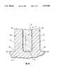
- FIG. 4Ais an elevational cross section view of two of the obstacles illustrated in FIG. 4 and the lattice pore therebetween taken along section line 4A--4A shown in FIG. 4;
- FIGS. 5A-5Fillustrate the steps in a method for manufacturing a sorting apparatus, such as the sorting apparatus illustrated in FIG. 1;
- FIG. 6is a plan view of the sorting apparatus shown in FIG. 1 with the obstacles enlarged to illustrate DNA molecules migrating through the array;
- FIG. 7is a plan view of an alternate embodiment of obstacles usable in an array in a sorting apparatus incorporating the teachings of the present invention wherein the obstacles are v-shaped;
- FIG. 8is a plan view of another alternate embodiment of obstacles usable in an array in a sorting apparatus incorporating the teachings of the present invention wherein the obstacles are cup-shaped;
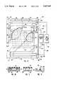
- FIG. 9is a plan view of yet another embodiment of a sorting apparatus incorporating the teachings of the present invention in which a pair of sensor electrodes are located within the array of the sorting apparatus;
- FIG. 10is a cross sectional elevation view of the apparatus shown in FIG. 9 taken along section line 10--10 shown therein, illustrating positioning of the top sensor electrode within the array of obstacles;
- FIG. 11is a cross sectional elevation view of the apparatus shown in FIG. 9 taken along section line 11--11 shown therein, illustrating positioning of the top sensor electrode;
- FIG. 12is a cross sectional elevation view of the sensing apparatus shown in FIG. 9 taken along section line 12--12 shown therein, illustrating positioning of the top sensor electrode outside of the array of obstacles;
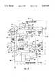
- FIG. 13is an electrical schematic diagram of the feedback circuit associated with the pair of sensor electrodes shown in the embodiment of the sensing apparatus illustrated in FIG. 9;
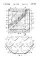
- FIG. 14is an enlarged plan view of another embodiment within the scope of the present invention illustrating a portion of a percolating array having cells migrating therein;
- FIG. 15is a perspective enlarged view of an alternate embodiment of obstacles for an array in a sorting apparatus incorporating the teachings of the present invention to stimulate cell behavior simulating the passage of such cells through the passageways in the human body;
- FIG. 16is a plan view of an embodiment of a sorting apparatus incorporating the teachings of the present invention utilizing obstacles of the type shown in FIG. 15 enlarged to illustrate cells deforming to migrate through the array thereof;
- FIGS. 17A-17Eillustrate in detail the movement of a healthy round cell between two adjacent obstacles of the type illustrated in FIGS. 15 and 16;
- FIGS. 18A-18Billustrate in detail the movement of an unhealthy cell unable to deform and pass through the restriction formed by two adjacent obstacles of the type illustrated in FIGS. 15 and 16.
- the present inventionprovides a method and apparatus that facilitates the fractionation of many types of microstructures.
- the present inventionallows successful fractionation of extremely long DNA molecules of chromosomal length in low quantities, such as even single molecules.
- the present inventionalso facilitates the fractionation of much larger microstructures, such as red blood cells.
- fractionation of DNA moleculesAlthough reference will be made herein to the fractionation of DNA molecules, it should be noted that fractionation of other macromolecules and microstructures, such as proteins, polymers, viruses, cells, and minute particles, is considered to be within the scope of the present invention.
- Sorting apparatus 20is illustrated for fractionating and simultaneously viewing microstructures such as free cells, macromolecules, and minute particles in a fluid medium in essentially a single layer.
- Sorting apparatus 20is comprised of a substrate 22 having a shallow receptacle 24 located on a side 26 thereof.
- receptacle 24is recessed in side 26 of substrate 22, although other structures for producing a recess such as receptacle 24 would be workable in the context of the present invention.
- Receptacle 24includes a floor 28 shown to better advantage in FIG. 2 bounded by a pair of upstanding opposing side walls 30, 31 and a first end 32 and a second end 34.
- the height of side walls 30, 31define a depth of receptacle 24.
- the depth of receptacle 24is commensurate with the size of the microstructures to be sorted in sorting apparatus 20.
- the depth of receptacle 24is specifically tailored to cause those microstructures in a fluid medium in receptacle 24 to form essentially a single layer. Thus, when the microstructures are caused to migrate in the fluid medium through receptacle 24, the microstructures do so in essentially the single layer.
- the migration of the microstructuresoccurs in a migration direction indicated by arrow M defined relative to sorting apparatus 20.
- Substrate 22may be comprised of any type material which can be photolithographically processed. Silicon is preferred, however other materials, such as quartz and sapphire can also be used.
- ceiling meansare provided for covering receptacle 24 intermediate first end 32 and second end 34 thereof and for causing the migration of the microstructures within receptacle 24 to occur in essentially a single layer.
- a coverslip 36extends across receptacle 24 in substrate 22 from one of the pair of upstanding opposing side walls 30 to the other of said pair of upstanding opposing side walls 31. The manner by which coverslip 36 is bonded to side 26 of substrate 22 will be discussed in detail subsequently.
- a sorting apparatussuch as sorting apparatus 20, is provided with sifting means positioned within receptacle 24 reversing the migration direction associated therewith for interacting with the microstructures to partially hinder the migration of the microstructures in the migration direction.
- one form of such a sifting means utilizable in accordance with the present inventionis an array 38 of minute obstacles 39 upstanding from floor 28 of receptacle 24. Obstacles 39 are sized and separated as to advance the particular sorting objective of sorting apparatus 20. The manner of forming obstacles 39 of array 38, as well as a number of examples of embodiments of obstacles utilizable in such an array, will be discussed in substantial detail below.
- Coverslip 36is so secured to the top of obstacles 39 in array 38 as to preclude migration of microstructures between the obstacles 39 and coverslip 36.
- Coverslip 36may optionally be transparent. In this form, coverslip 36 performs not only the function of the ceiling means described above, but also performs the function of a capping means for covering a shallow receptacle, such as receptacle 24, and for affording visual observation therethrough of the migration of microstructures through array 38.
- Coverslip 36may be comprised of any ceramic material. Pyrex is preferred, but other materials such as quartz and sapphire, for example, may also be used.
- a sorting apparatussuch as sorting apparatus 20
- electric force meansfor generating an electric field in the fluid medium in receptacle 24.
- the electric fieldinduces the microstructures to migrate through the fluid medium, either from first end 32 to second end 34 or from second end 34 to first end 32, depending upon the polarity of the electric field and whether the microstructures are positively or negatively charged.
- Negatively charged microstructures, such as DNA moleculeswill be induced to flow toward the positive pole.
- Positively charged microstructures, such as proteinswill be induced to flow toward the negative pole.
- first electrode 40is shown in FIG. 2 as being located in first end 32 of receptacle 24 and a second electrode 42 located in second end 34 of receptacle 24.
- First electrode 40 and second electrode 42each comprise a metal strip disposed on floor 28 of receptacle 24.
- the metal stripis formed from evaporated gold.
- a battery 44, or other power sourceis electrically coupled between first and second electrodes, 40 and 42, such that first electrode 40 comprises a negative pole and second electrode 42 comprises a positive pole.
- the electric field generated between first and second electrodes, 40 and 42,is non-alternating, but the use of an alternating power source in place of battery 44 would be consistent with the teachings of the present invention.
- the electric field intensity in receptacle 24is in the range of from about 0.1 volt per centimeter to about 10 volts per centimeter. In the preferred embodiment, an electric field intensity is about 1.0 volt per centimeter.
- FIG. 3illustrates one example of a sifting means for use in a sorting apparatus of the present invention.
- array 38comprises a plurality of obstacles 39 upstanding from floor 28 of receptacle 24.
- FIG. 3illustrates obstacles 39 as being positioned within array 38 in an ordered and uniform pattern, it is within the scope of the present invention to have a staggered pattern, or any desired predetermined and reproducible pattern.
- FIG. 4illustrates the various dimensions of a typical obstacle 39.
- the height H of obstacle 39is measured in a direction normal to floor 28 of receptacle 24.
- the length L of obstacle 39is measured in a direction parallel to said migration direction M.
- the width W of obstacle 39is measured in a direction normal to the migration direction M.
- Each of the obstacles 39are separated from an adjacent obstacle 39 by a predetermined separation distance S d .
- the space between adjacent of obstacles 39 in a cross section of array 38 taken normal to floor 28 of receptacle 24defines a pore 54 of the lattice structure cumulatively produced by obstacles 39 of array 38.
- a typical pore 54has been shaded, but will be discussed in additional detail subsequently.
- the separation distance S dwill vary depending upon whether the migration of microstructures through pores 54 are DNA molecules, viruses and bacterial cells, or mammalian cells.
- the separation distance S dis within the range of about 0.01 microns to about 20.0 microns.
- the separation distance S dis within the range of about 0.01 microns to about 1.0 micron.
- the separation distanceis within the range of from about 1.0 micron to about 50.0 microns. It is presently preferred that the separation distance S d be substantially equal to the radius of gyration of the molecule, the radius of gyration being the distance walking out from the center of the molecule.
- Length Lalso varies depending upon the microstructure to be migrated through array 38 of obstacles 39.
- the lengthis generally equal to the separation distance.
- the height of obstaclesmay generally be in the range of from 0.01 microns to about 20.0 microns.
- the obstaclesmay have a height in a range from about 0.01 microns to about 0.50 microns.
- the heightmay be in the range from about 1.0 micron to about 5.0 microns.
- FIG. 4Aa cross-section of two obstacles 39, illustrates in planar view a typical pore 54.
- Pore 54compresses the area defined by two obstacles 39 through which a microstructure must pass.
- Pore 54is defined by the height H and the separation distance S d between the obstacles.
- the desired size of pore 54is determined by reference to the size of the microstructures to be sorted therethrough.
- An important aspect with the apparatus of the present inventionis that not only is the pore size of the arrays known, but it is also constant and reproducible. More stable data can be obtained.
- the characteristic number which sets the length scale for the conformation of a polymer in solutionis the persistence length given by the equation: ##EQU1## E is the Young's modulus, I A is the surface moment of inertia,
- K Bis Boltmann's constant
- Tis the absolute temperature
- etch depth of the arrayis approximately equal to or less than P then the polymer can be viewed as moving in a quasi-two-dimensional environment, as is the case in the apparatus used within the scope of the present invention.
- substrate 22is provided with a receptacle 24 having sides 30 and 31 of approximately 3.0 millimeters in length and first and second ends 32, 34, respectively, of approximately 3.0 millimeters in length.
- Each of obstacles 39has a height H of approximately 0.1 microns, a width W of approximately 1.0 micron, a length L of approximately 1.0 micron and a separation distance S d of approximately 2.0 microns. These sizes will vary depending upon the microstructure to be sorted, bearing in mind that obstacles 39 should be so sized and separated in array 38 that microstructures migrate through array 38 of obstacles 39 in essentially a single layer.
- the method of making the apparatus of the present inventioninvolves forming receptacle 24 on one side of substrate 22.
- Receptacle 24should be formed of a size such that microstructures migrate in the fluid through receptacle 24 in essentially a single layer.
- a further stepcomprises creating array 38 of obstacles 39 within receptacle 24.
- Each of obstacles 39have a top 56, sides 57, and a bottom end 58. Obstacles 39 are upstanding from floor 28 of receptacle 24 in a predetermined and reproducible pattern.
- the array of obstaclescomprises a plurality of posts.
- the creation of posts within the receptacleis illustrated in FIGS. 5A-5F.
- the forming stepcomprises developing a photosensitive photoresist layer 60 over areas of substrate 22 that are intended to correspond to tops 56 of obstacles 39. This is accomplished by exposing substrate 22 to light through a mask having thereon a corresponding opaque pattern.
- FIG. 5Billustrates substrate 22 with photoresist layer 60 thereon after exposure to light and development in solution.
- the next stepcomprises etching substrate 22 such that the areas of substrate 22 unshielded by photoresist layer 60 are exposed to the etching, thereby forming receptacle 24.
- the array 38 of obstacles 39 upstanding within the etched receptacle 24is formed by the portions of substrate 22 shielded by photoresist layer 60.
- FIG. 5Cillustrates formation of receptacle 24 and the obstacles 39.
- FIG. 5Cillustrates the receptacle 24 half formed, and photoresist layer 60 partially etched away. If, for example, the photoresist layer is etched at a rate 1/10 the rate that substrate 22 is etched, the resulting receptacle can at most have a depth 10 times the thickness of the photoresist layer. The thickness of photoresist layer 60 must therefore be chosen accordingly.
- the etching processcan be terminated at any time when the desired depth of the receptacle is reached. As illustrated in FIG. 5D, there may be some photoresist layer 60 still present on substrate 22 when the etching is terminated. If so, the next step is then dissolving photoresist layer 60 from substrate 22. This step leaves a clean substrate 22 as shown in FIG. 5E.
- etchingmay occur by many types of methods.
- ion millingis used such that an overhead ion beam is used to etch the substrate 22 and photoresist layer 60.
- Other methods of etchingsuch as chemical etching, are also within the scope of the present invention.
- the stepcomprises positioning coverslip 36 over array 38 of obstacles 39 such that coverslip 36 is in contact with each of obstacles 39, and then applying an electric field between coverslip 36 and each of obstacles 39.
- the coverslip 36is held with a negative potential.
- the obstacles 39are held at a positive potential. Ions are thereby induced to migrate there between to create a bond between coverslip 36 and each of obstacles 39 at all areas of contact.
- the process of this stepis referred to as field assisted fusion.
- the voltage used to fuse coverslip 36 to the substrate 22is preferably about 1 kilovolt but can be within the range of from 200 volts to about 2000 volts.
- the time for fusionis about 30 minutes at a temperature of about 400° C.
- the temperaturecan also range from about 300° C. to about 600° C., with 400° C. being the preferred temperature.
- the coverslipcomprises a pyrex material.
- any transparent ceramicmay be used.
- sapphire and quartzare material which may also be used for the coverslip.
- coverslip 36it is preferred that the material used for coverslip 36 have substantially the same coefficient of thermal expansion as substrate 22. Otherwise, at the high temperature of fusion, the coverslip 36 and the substrate 22 will expand at different rates and a seal between the two would be difficult or impossible to accomplish.
- FIG. 6illustrates one use of an embodiment of the present invention.
- the apparatus of the present inventioncan be used for charged macromolecular electrophoresis.
- the apparatusmay be used to conduct protein electrophoresis, and DNA electrophoresis, with the positive and negative poles adjusted accordingly.
- FIG. 6illustrates DNA electrophoresis.
- DNA molecules 68are placed into a buffer solution and placed into a loading area 66 positioned on the first end 32 of receptacle 24.
- Loading area 66comprises a portion of receptacle 24 where no obstacles 39 have been formed.
- Bufferis also added to a second loading area 67 positioned on second end 34.
- Second loading area 67also comprises a portion of receptacle 24 where no obstacles have been formed. The loading areas are then covered.
- battery 44is engaged and an electric field is generated.
- the electric fieldis so polarized as to induce the negatively charged DNA microstructures to migrate through the field from first electrode 40 toward second electrode 42 in receptacle 24.
- DNA molecules 68migrate from first end 32 toward the second end 34, their movements are hindered by the array 38 of obstacles 39 upstanding within receptacle 24. Interaction between obstacles 39 and DNA molecules 68 are illustrated in FIG. 6.
- DNA molecules 68are illustrated as long arrows. The direction of the arrows indicates the direction of migration of DNA molecules 68.
- large bodies of DNA moleculesmay become hooked by obstacles 39 and may become trapped.
- the hooked and trapped DNA moleculesare labelled as 68a.
- obstacles 39are posts, DNA molecules 68 stretch around obstacles 39 as they become hooked. The obstacles are thought to catch the large DNA molecules and hold them against the electric field. Some DNA molecules 68 may stretch and release themselves from the obstacles. Smaller DNA molecules possess sufficient Brownian motion to release themselves.
- any pattern of array 38 of obstacles 39can be designed within the scope of the present invention.
- the array 38can comprise an ordered, evenly spaced formation wherein the obstacles are positioned in uniform rows and columns.
- array 38may comprise a staggered formation wherein positioning of the obstacles is not uniform but rather scattered around the array.
- array 38may comprise a mixture of such arrangements disposed along migration direction M traversing same.
- the design of the arraycan be formulated to correspond to any specific intended use.
- the ordered, evenly spaced configurationcan be used for imaging of long megabase DNA fragments.
- the staggered configurationhaving a higher possibility of hooking the DNA molecules as the DNA molecules migrate through the array, can be used to more directly test the role of DNA relaxation and hooking in the mobility of DNA molecules.
- the shapes of the obstaclesmay also vary within the scope of the present invention. Illustrated in FIG. 7 is an array 70 of v-shaped obstacles 72 upstanding from floor 28 of receptacle 24, and having a v-shaped cross section in a plane disposed parallel to floor 28 of receptacle 24. Arms 73 and 74 intersect at one end to form a vertex 75 and an open end 76. The open end 76 of said v-shaped cross section of v-shaped obstacles 72 is disposed opposing migration direction M of receptacle 24.
- v-shaped obstacles 72should be such that as microstructures of various sizes migrate through the array 70 of v-shaped obstacles 72 in a direction M, the microstructures are hindered and trapped within the open end 76 of v-shaped obstacles 72. Smaller v-shaped obstacles 72 will trap small microstructures while larger v-shaped obstacles 72 will trap both the smaller and the larger microstructures.
- v-shaped obstacles 72may be used within one array 70.
- smaller v-shaped obstacles 72may be positioned toward the first end 32 of receptacle 24 with larger v-shaped obstacles 72 positioned toward the second end 34 of receptacle 24.
- the smaller microstructureswill become trapped in the smaller v-shaped obstacles 72 while the larger microstructures will flow past the smaller v-shaped obstacles 72.
- the larger microstructureswill also become trapped. The microstructures will then be separated with respect to size.
- FIG. 8illustrates an array 78 of obstacles 80 which are cup-shaped. Obstacles 80 have a cup-shaped cross section in a plane disposed parallel to floor 28 of receptacle 24.
- cup-shaped obstacles 80may comprise a first leg 82 and a second leg 84 substantially parallel to the direction of migration of the microstructures, and a third leg 86 substantially perpendicular to the direction of migration.
- First, second, and third legs, 82, 84, and 86, respectively,are positioned such that they define an open end 88 into which the microstructures can become trapped as the microstructures migrate through the cup-shaped obstacles 80.
- various sizes of cup-shaped obstacles 80may be positioned within array 78 in any pattern desired.
- the open end 88 of the cup-shaped cross-sectionis disposed opposing migration direction M of receptacle 24.
- a sorting apparatus 110is comprised of an apparatus, such as sorting apparatus 20, further provided with sensor means for detecting the intensity of the electric field generated within the array of obstacles, such as array 38 of obstacles 39, between any determined first and second points therein, to enable control of the intensity of the electric field.
- Sorting apparatus 110is illustrated in FIG. 9. As in sorting apparatus 20, shown in FIGS. 1 and 2, sorting apparatus 110 includes first electrode 40 and second electrode 42, functioning as negative and positive poles, for an electric field generated therebetween. That field may be non-alternating, by coupling therebetween a battery, such as battery 44 of FIGS. 1 and 2. Nevertheless, it would also be consistent with the teachings of the present invention to develop an electric field that is alternating or switchable as to polarity, either selectively or according to some repeated pattern. In the case of sorting apparatus 110, however, the electric field developed between first and second electrodes 40 and 42 is produced by a feedback varied drive voltage circuit 144 that will be explored in detail subsequently.
- First electrode 40comprises a metal strip positioned along floor 28 of receptacle 24 at first end 32.
- First electrode 40is soldered to substrate 22 and to various lead lines at a first area 128.
- Second electrode 42comprises a metal strip positioned along floor 28 of receptacle 24 at second end 34. Second electrode 42 is soldered to substrate 22 and to various lead lines at a second area 129.
- the metal strips, first and second electrodes 40 and 42comprise gold evaporated into floor 28.
- sensor meansPositioned within the array is sensor means for detecting the intensity of the electric field generated between first electrode 40 and second electrode 42 between predetermined first and second points therein.
- the sensor meansenables control of the intensity of the electric field generated.
- the sensor meanscomprises a first sensor electrode 130 positioned within array 38 of obstacles 39 at the first predetermined point 134.
- the sensor meansfurther comprises a second sensor electrode 132 which is positioned within array 38 of obstacles 39 at the second predetermined point 135.
- First sensor electrode 130is positioned within array 38 toward first end 32 of receptacle 24 in a first sensor channel 138 formed along floor 28 of receptacle 24. No obstacles 39 are present within channel 138. A clear area is formed wherein the sensor electrode is positioned.
- the array 38is turned at a 45 degree angle before the sensor electrodes are positioned within the array.
- first and second sensor electrodes, 130 and 132extend through sidewall 31 of receptacle 24, past coverslip 36, and onto substrate 22. Positioning of first sensor electrode 130 can be seen in FIGS. 10-12.
- first sensor electrode 130is shown disposed along floor 28 of receptacle 24 within first sensor channel 138. Obstacles 39 can be seen positioned along the sides of top sensor channel 138, but not within channel 138 itself. Coverslip 36 is shown fused to the obstacles 39 and covering channel 138.
- FIG. 11illustrates channel 137 extending away from sidewall 31 of receptacle 24. Obstacles are not present within channel 137. Coverslip 36 is illustrated in FIG. 11 as positioned over channel 137.
- FIG. 12illustrates the first sensor soldering area 140 where first sensor electrode 130 is soldered to the substrate 22 and connected to first sensor lead 152, to be later discussed in more detail.
- second sensor electrode 132is positioned within apparatus 110 in the same fashion. Second sensor electrode 132 is positioned within a bottom sensor channel 139 within the array 38 of obstacles 39. Second sensor electrode 132 is soldered to substrate 22 and connected to a second sensor lead 154 at a second sensor soldering area 142. Second sensor lead 154 will be later discussed in more detail.
- First electrode 40is electrically coupled to drive voltage circuit 144 by first electrode lead 146 soldered to first electrode 40 at a first electrode soldering area 128.
- Second electrode 42is grounded by way of a first ground lead 148 that is connected to second electrode 42 at a second electrode soldering area 129.
- First and second sensor electrodes, 130 and 132are electrically coupled to each other and to drive voltage circuit 144 through a feedback circuit 150.
- a first sensor electrode lead 152connects the first sensor electrode 130 to feedback circuit 150.
- a second sensor electrode lead 154connects the second sensor electrode 132 to feedback circuit 150.
- a second ground lead 156connects feedback circuit 150 to the ground.
- a control lead 158connects feedback circuit 150 to drive voltage circuit 144.
- a feedback circuitsuch as feedback circuit 150 in FIG. 9, and a drive voltage circuit, such as drive voltage circuit 144 in FIG. 9, can be appreciated by reference to FIG. 13.
- receptacle 24is filled with a liquid medium in which the input voltage V I supplied between first electrode 40 and grounded second electrode 42 creates an electric field.
- the actual voltage V A created in the liquid medium in receptacle 24 between first sensor electrode 130 and second sensor electrode 132is illustrated as a voltage drop occurring over a variable resistor 159.
- Resistor 159represents the resistance to the electric field presented in the liquid medium in receptacle 24 between the first and second predetermined points in array 38.
- the composition of the liquid mediumwill vary from a number of causes. This as a result varies the electrical resistance of the liquid medium.
- the actual voltage V Ainherently differs from the input voltage V I by the amount of voltage drop occurring in the liquid medium at two locations. These are between first electrode 40 and first sensor electrode 130 and between second sensor electrode 132 and second electrode 42.
- the resistance in the liquid medium in receptacle 24 between first electrode 40 and first sensor electrode 130is illustrated as a resistor 160a, while the corresponding resistance between second sensor electrode 132 and second electrode 42 is illustrated as a resistor 160b.
- FIG. 13illustrates in addition an exemplary arrangement of circuit elements intended to perform the functions of drive voltage circuit 144 and feedback circuit 150 illustrated in FIG. 9.
- a sorting apparatussuch as sorting apparatus 110 is also provided with electric force means for generating the electric field in the fluid medium in receptacle 24.
- electric force meansfor generating the electric field in the fluid medium in receptacle 24.
- FIG. 1one example of such an electric force means was illustrated in the form of battery 44.
- drive voltage circuit 144comprises an original voltage V 0 which is coupled through an input resister 161 to the negative terminal of a differential amplifier 162. In this manner, the voltage appearing on first electrode lead 146 coupled to the output terminal of differential amplifier 162 has an inverse polarity relative to input voltage V 0 .
- a biasing resister 163is coupled in parallel between the negative input terminal of differential amplifier 162 and the output terminal thereof.
- input voltage V 0may comprise a battery
- sorting apparatus 110it is also the intention in sorting apparatus 110 to afford for an input voltage V 0 , which can itself be variable and which, due to the coupling thereof through the negative input terminal of differential amplifier 162, is inversely variable relative to the input voltage V I that is eventually supplied over first electrode lead 146 to first electrode 40.
- a sorting apparatussuch as sorting apparatus 110 illustrated in FIG. 9, includes sensor means for detecting the intensity of the electric field generated within the liquid medium in receptacle 24 in any preselected portion of array 38.
- the electric field detectedcorresponds to actual voltage V A illustrated in FIG. 13.
- the preselected portion of array 38 over which actual voltage V A is measuredis located between a first predetermined point 134 in array 38 corresponding to first sensor electrode 130 and a second predetermined point 135 therein corresponding to second sensor electrode 132.
- FIG. 13illustrates an example of circuit elements capable of performing the function of such a sensor means for use in a sorting apparatus incorporating teachings of the present invention.
- These elementsinclude first sensor electrode 130 positioned within array 38 of obstacles 39 at first predetermined point 134 and a second sensor electrode 132 positioned within array 38 at second predetermined point 135.
- the sensor apparatusaccording to the teachings of the present invention comprises control means coupled to first sensor electrode 130 and second sensor electrode 132 for maintaining the electric field in the liquid medium in receptacle 24 at a predetermined intensity.
- FIG. 13The elements of one embodiment of such a control means are shown in FIG. 13 in the form of the circuit components and functional groupings thereof that comprise feedback circuit 150.
- Feedback circuit 150functions to vary the voltage supplied by drive voltage circuit 144 to first electrode 40 utilizing a control signal supplied thereto over control lead 158. While the elements of feedback circuit 150 will be described in detail subsequently, the effect of the control signal supplied over control lead 158 to drive voltage circuit 144 will be better appreciated fully by an initial discussion of the constituent elements of drive voltage circuit 144.
- control lead 158The control signal from control lead 158 is applied to the positive input terminal of differential amplifier 162 through a second input resistor 164.
- the effect of the control signal on control lead 158is to vary the output of drive voltage circuit 144 on first electrical lead 146 with the object of stabilizing actual voltage V A .
- the intensity of the electric field in the fluid medium in receptacle 24is increased, when the control signal indicates that the actual voltage V A is less than some predetermined referenced voltage desired by the operator of sorting apparatus 110.
- the control signal of control lead 158is oppositely polarized and thus decreases the intensity of the electric field in the liquid medium in receptacle 24, when the control signal reflects that the actual voltage V A is greater than that same predetermined reference voltage. In this manner, the control signal supplied on control lead 158 to drive voltage circuit 144 will by the action of differential amplifier 162 adjust the actual effect of original voltage V 0 so as to maintain the actual voltage V A at any desired level.
- control signal supplied over control lead 158 to drive voltage circuit 144could be utilized as a mechanism for effecting desired variations in the voltage supplied to first electrode 40 on first electric lead 146.
- control signal supplied over control lead 158 to drive voltage circuit 144could be utilized as a mechanism for effecting desired variations in the voltage supplied to first electrode 40 on first electric lead 146.
- An initial objective of the circuitry that will now be described relative to feedback circuit 150is to compensate for what is in effect the changeable nature of the liquid medium in receptacle 24 as illustrated by variable resistor 159. In this manner actual voltage V A is maintained at some predetermined constant intensity.
- feedback circuit 150includes a differential amplifier circuit 166 having a first input terminal 167, a second input terminal 168, and an output terminal 169.
- First input terminal 167is coupled through a first buffer amplifier circuit 170 to first sensor electrode 130, while second input terminal 168 is coupled through a second buffer amplifier circuit 171 to second sensor electrode 132.
- First buffer amplifier circuit 170is comprised of a differential amplifier 172 connected in the manner illustrated between the circuit components already described above.
- second buffer amplifier circuit 170is comprised of a differential amplifier 173 connected as illustrated. It is the function of first and second amplifier circuits 170, 171, respectively, to serve as impedance buffers for first and second input terminals 167, 168, respectively, of differential amplifier circuit 166.
- first input terminal 167is coupled through an input resistor 174 to the negative input terminal of a differential amplifier 175, while second input terminal 168 is coupled to the positive terminal thereof through an input resistor 176.
- Resistors 177 and 178are connected as shown in FIG. 13 to bias differential amplifier 175 into the desired operator thereof.
- differential amplifier circuit 166produces at output terminal 169 thereof an output signal that corresponds to the intensity of actual voltage V A of the electric field in the liquid medium in receptacle 24.
- a feedback circuitsuch as feedback circuit 150, includes a comparator means coupled to output terminal 169 of differential amplifier circuit 166 for producing a control signal at control lead 158 that reflects the difference between the output signal on output terminal 169 and a reference voltage reflecting a predetermined desired intensity of actual voltage V A .
- such a reference voltageis supplied by a reference voltage circuit 179 which comprises a differential amplifier 180 having a reference voltage V R coupled to the positive input terminal thereof through a variable resistor 181.
- variable resistor 181can be used to adjust the effect of reference voltage V R appearing at the output side of differential amplifier 180 at an output terminal 182 for reference voltage circuit 179.
- comparison circuit 183It is the purpose of comparison circuit 183 illustrated in FIG. 13 to produce on control lead 158 a control signal reflecting the difference, if any, between the output signal appearing at output terminal 169 of differential amplifier circuit 166 and the portion of reference voltage V R appearing at output terminal 182 of reference voltage circuit 179.
- comparison circuit 183comprises a differential amplifier 184 coupled at the output terminal thereof to control lead 158.
- the positive input terminal of differential amplifier 184is coupled through an input resistor 185 to output terminal 169 of differential amplifier circuit 166, while the negative input terminal of differential amplifier 184 is coupled through an input resistor 186 to output terminal 182 of reference voltage circuit 179.
- Variable resistors 187, 188are connected as shown within comparison circuit 183 to effect desired biasing of differential amplifier 184.
- differential amplifiers 162, 172, 173, 175, 180, and 184can, by way of example, comprise operational amplifiers available from Analog Devices as Product No. AD795N. Such devices utilize field effect transistor inputs and have low noise characteristics.
- the values of the resistors illustratedare as follows:
- original voltage V 0is equal to negative 15 volts
- reference voltage V Ris equal to positive 15 volts
- any desired predetermined actual voltage V Acan be maintained between first and second sensor electrodes 130, 132, respectively, despite variations over time in the nature of the liquid medium in receptacle 24.
- FIGS. 14-18illustrate another use of the teachings of the present invention to facilitate the study of the motion of cells, such as human red blood cells, bacterial cells, and cancer cells, for example, through channels in a single layer and in single file.
- the channelsmay simulate those found in capillaries, the lung alveoli, and the spleen in the human body.
- red blood cellscan be fractionated on the basis of physical properties which are otherwise difficult to probe by biological markers.
- the apparatus within the scope of the present inventioncomprises channeling means positioned within receptacle 24 for allowing passage of cells through receptacle 24 in essentially a single layer and in single file.
- FIG. 14One possible configuration of an array for all fractionation within the scope of the present invention is illustrated in FIG. 14.
- This array 192is called a percolating array and is patterned as a maze.
- the channeling meanscomprises obstacles 193 positioned upstanding from floor 28 of receptacle 24 in various connecting positions to form open areas 194, passageways 196, and dead ends 197, such as are found in mazes.
- cells 199migrate through percolating array 192 through open areas 194 and passageways 196 and are at times blocked by dead ends 197.
- Passageways 196may be made linear, curved, or whatever shape desired so as to be able to observe migration of cells through variously shaped passageways.
- Passageways 196may have a width in the range of from about 1.0 micron to about 10.0 microns and a depth with the range of from about 1.0 micron to about 10.0 microns. Cells migrating in single file can be seen labelled as 199a.
- Percolationis the phenomenon of increasing path connectedness due to random addition of discrete segments to allowed motion. At the percolation threshold, there is just one path on the average through the array, with all other paths leading to dead ends. The ability of cells to find that path can be observed with the percolating arrays 192 of the present invention.
- percolating arrays 192have been constructed on a rectangular lattice in a preferred percolating embodiment.
- a single computer algorithmfills some fraction of the lattice with lines, for example, 40% so as to form the variety of open areas 194 and passageways 196.
- the computer programis then made into the opaque mask and the microlithographic process as earlier described is carried out.
- the obstacles 193are comprised of barriers 5.0 microns long and 1.0 micron wide.
- the preferred etch depth of percolating array 192is 0.35 microns.
- FIG. 14illustrates an enlarged section of such a photomicrograph percolating array 192.
- percolating array 192is for study of the movements of cells, such as E. coli, from one end of array 192 to the other.
- E. coli cellswere placed at the first end 32 of receptacle 24 while food was placed at the second end 34 of receptacle 24.
- the E. coli cellswere then observed as they migrated in a single layer through percolating array 192 from first end 32 toward second end 34.
- dead ends 197were reached by the E. coli cells, the manner in which the E. coli cells reoriented themselves in order to move away from the dead ends 197 was observed. Also observed was the ability of the E. coli cells to find an open path from the starting point at first end 32 to the food at second end 32.
- Percolating arrays 192can be used to study the manner in which many other types of free floating cells reorient themselves in a fluid suspension when confronted with barriers and passageways, and the manner in which various passageways are chosen.
- the percolating arrays 192are formed such that migration of a cell in a single layer and single file can be observed. Therefore, in order to accommodate the various sizes of cells to be observed, the size of open areas 194 and passageways 196 in each array 192 can be designed as needed.
- the pattern of the arraycan also be designed as desired. Any pattern can be produced and reproduced.
- percolating arrays 192One additional important aspect of percolating arrays 192 is the ability to perform electrophoresis of charged spherical balls within percolating arrays 92.
- the mobilities of even simple ballsare rich in a percolating array because of the numerous dead-ends that exist in a percolating array near the percolating threshold. If the electric fields are too big, then the balls cannot back-diffuse out of the dead end against the applied electric force. Hence, mobility shuts down above a critical field. Measuring the diffusion of fluorescent balls of precise diameter will allow study of a diffusion of polymers in arrays.
- an array 200 of obstacles in the form of elongated rectangular bunkers 202is positioned within receptacle 24.
- Bunkers 202are comprised of a rectangular shape having opposing sidewalls 203 and a top 204.
- Bunkers 202upstand from floor 28 of receptacle 24.
- Bunkers 202are positioned within columns and rows within receptacle 24.
- Cellsmigrate through the columns and between the rows of bunkers 202 in a migration direction indicated by arrow M.
- the longitudinal axis of the bunkersare disposed in alignment with migration direction M.
- Channels 206are formed between rows of bunkers 202 through which the cells migrate.
- a separation distance, S rbetween rows of bunkers 202, indicates the size of channels 206.
- bunkers 202While the size and organization of bunkers 202 may vary, in a preferred embodiment within the scope of the present invention, the separation distance S r is sized to allow the cells to migrate through channels 206 in essentially a single layer in single file.
- each bunker 202should also be such that it allows the cells to pass through the bunkers 202 in essentially a single layer.
- a coverslip 36is fused to the tops 204 of bunkers 202 so as to prevent migration of cells between the coverslip and the tops 204 of bunkers 202 to ensure that the cells migrate through the array 200 of bunkers 202 in essentially a single layer.
- bunkers 202are the preferred obstacles for forming channels 206, different structures may also be used to simulate channels through which the cells can migrate and be observed. These alternate structures are also within the scope of the present invention.
- FIG. 16illustrates an apparatus 212 for cell sorting and fractionation.
- cells 214are shown migrating through array 200 of bunkers 202. Cells 214 can be seen moving between the rows of bunkers 202 through channels 206. Some cells begin round, deform to fit within channels 206, and then regain their shape once out of the channel. Other cells which may have lost some degree of deformability, however, do not regain their shape, or are misshapen initially. Some are even trapped in these, restricted channels. This, as earlier stated, can be caused by aging, sickling or other in vivo or in vitro problems.
- cells 214are shown to be disc shaped. As cells 214 enter channels 206, cells 214 deform from a disc shape to an elongated shape so as to be able to squeeze through channels 206. When cells 214 are positioned between bunkers 202 and within channels 206, cells 214 have a thin elongated shape. As cells 214 move from between bunkers 202 and into open space, the healthy cells 214 can be seen to resume their original disc shapes. The unhealthy cells may be found to not be able to resume their original shapes because of a lack of plastic flow. By the apparatus of the present invention, the flexibility and deformability of red blood cells can be studied.
- FIGS. 17A-17Eillustrates an individual cell 214 moving through a pair of bunkers 202.
- the cell 214is perfectly disc shaped.
- FIG. 17Bcell 214 is seen beginning to deform in order to fit between bunkers 202 in channel 206.
- FIG. 17Cillustrates cell 214 deformed into an elongated thin shape to fit within channel 206.
- FIG. 17Das cell 214 begins to move out of channel 206, cell 214 begins to regain its original disc shape.
- the elasticity of cell 214allows cell 214 to completely regain its original disc shape.
- FIGS. 18A-18Billustrate an unhealthy cell 216 whose elastic properties have been lost.
- unhealthy cell 216has an original round disc shape of a healthy cell, its flexibility is diminished such that it cannot deform to fit into channel 206.
- cell 216cannot deform into a thin elongated shape to fit into channel 206 and becomes stuck in the opening of channel 206.
- cancer cellsit is thought that where the cancer cells become stuck, a new tumor is grown.
- the activity of cancer cellscan be studied with the teachings of the present invention.
- the apparatus of the present inventionby using the apparatus of the present invention, the elasticity and flexibility of cells can be studied. Further, the consequences of lack of plastic flow of the cells can be observed and studied. Further, still, the amount of energy consumed by the cell to deform and regain its shape can easily be measured and recorded.
- Array 200can be exposed to various chemical environments, such as irradiation, light illumination, or sickling phenomena imitations, before allowing the cells to migrate through array 200.
- the reactions of cells as they migrate through these various environmentscan then be studied. For example, experiments can be designed to determine what kinds of chemical reactions cause aging of the cells and destroy ability of cells to be flexible. Other experiments can be designed and conducted to determine the chemical effects on cancer cells. Ultimately, an unlimited number of cellular effects can be observed.
- cellscan be sorted by desired physical properties, that is, by their reactions to various environments. As the cells are sorted, they can be separated and collected.
- Another important advantage of the present invention with regard to studying cellsis the reproducibility and repeatability of the array of obstacles. Since the arrays 200 can consist of obstacles which are repeated thousands of times, even subtle variations in small quantities in the membrane of the cell can be amplified. Additionally, by the apparatus of the present invention, many individual cells can be observed at once as they migrate through the channels 206 of the apparatus. Observation of more than just one cell is possible.
- cellscan be migrated through array 200 using various fields.
- migrationcan be caused by flowing fluid through the array in a hydrodynamic field through flow cytometry wherein water pressure is used to force the cells through the array.
- the cellsmay also be induced to move by a gravity field.
- magnetic beadsmay be placed on the apparatus to create a magnetic field to induce movement of the cells.
- focused beams of lightreferred to as optical tweezers may be used to move the cells through array 200.
- Other means for inducing the cells to migrate through the array 200are also within the scope of the present invention.
- the apparatuscan be designed to simulate capillaries in the human body by having channeling means positioned within receptacle 24 which mimic the openings that the blood cell must pass through in the body.
- channeling meanspositioned within receptacle 24 which mimic the openings that the blood cell must pass through in the body.
Landscapes
- Chemical & Material Sciences (AREA)
- Health & Medical Sciences (AREA)
- Life Sciences & Earth Sciences (AREA)
- General Health & Medical Sciences (AREA)
- Molecular Biology (AREA)
- Chemical Kinetics & Catalysis (AREA)
- Dispersion Chemistry (AREA)
- Engineering & Computer Science (AREA)
- Analytical Chemistry (AREA)
- Organic Chemistry (AREA)
- Physics & Mathematics (AREA)
- Biotechnology (AREA)
- Zoology (AREA)
- Wood Science & Technology (AREA)
- Biochemistry (AREA)
- Hematology (AREA)
- Clinical Laboratory Science (AREA)
- Bioinformatics & Cheminformatics (AREA)
- Electrochemistry (AREA)
- General Physics & Mathematics (AREA)
- Cell Biology (AREA)
- Biomedical Technology (AREA)
- Microbiology (AREA)
- Sustainable Development (AREA)
- Pathology (AREA)
- Immunology (AREA)
- General Engineering & Computer Science (AREA)
- Genetics & Genomics (AREA)
- Fluid Mechanics (AREA)
- Apparatus Associated With Microorganisms And Enzymes (AREA)
Abstract
Description
Claims (75)
Priority Applications (7)
| Application Number | Priority Date | Filing Date | Title |
|---|---|---|---|
| US08/074,432US5427663A (en) | 1993-06-08 | 1993-06-08 | Microlithographic array for macromolecule and cell fractionation |
| CA002164720ACA2164720A1 (en) | 1993-06-08 | 1994-06-03 | Microlithographic array for macromolecule and cell fractionation |
| EP94919332AEP0711412A4 (en) | 1993-06-08 | 1994-06-03 | MICROLITHOGRAHIC ARRAY FOR MACROMOLECULAR AND CELLULAR FRACTIONATION |
| JP7501939AJPH09504362A (en) | 1993-06-08 | 1994-06-03 | Microlithographic array for fractionation of macromolecules and cells |
| PCT/US1994/006215WO1994029707A1 (en) | 1993-06-08 | 1994-06-03 | Microlithographic array for macromolecule and cell fractionation |
| MYPI94001434AMY111272A (en) | 1993-06-08 | 1994-06-06 | Microlithographic array for macromolecule and cell fractionation |
| US08/474,688US5837115A (en) | 1993-06-08 | 1995-06-07 | Microlithographic array for macromolecule and cell fractionation |
Applications Claiming Priority (1)
| Application Number | Priority Date | Filing Date | Title |
|---|---|---|---|
| US08/074,432US5427663A (en) | 1993-06-08 | 1993-06-08 | Microlithographic array for macromolecule and cell fractionation |
Related Child Applications (1)
| Application Number | Title | Priority Date | Filing Date |
|---|---|---|---|
| US08/474,688DivisionUS5837115A (en) | 1993-06-08 | 1995-06-07 | Microlithographic array for macromolecule and cell fractionation |
Publications (1)
| Publication Number | Publication Date |
|---|---|
| US5427663Atrue US5427663A (en) | 1995-06-27 |
Family
ID=22119534
Family Applications (2)
| Application Number | Title | Priority Date | Filing Date |
|---|---|---|---|
| US08/074,432Expired - LifetimeUS5427663A (en) | 1993-06-08 | 1993-06-08 | Microlithographic array for macromolecule and cell fractionation |
| US08/474,688Expired - LifetimeUS5837115A (en) | 1993-06-08 | 1995-06-07 | Microlithographic array for macromolecule and cell fractionation |
Family Applications After (1)
| Application Number | Title | Priority Date | Filing Date |
|---|---|---|---|
| US08/474,688Expired - LifetimeUS5837115A (en) | 1993-06-08 | 1995-06-07 | Microlithographic array for macromolecule and cell fractionation |
Country Status (6)
| Country | Link |
|---|---|
| US (2) | US5427663A (en) |
| EP (1) | EP0711412A4 (en) |
| JP (1) | JPH09504362A (en) |
| CA (1) | CA2164720A1 (en) |
| MY (1) | MY111272A (en) |
| WO (1) | WO1994029707A1 (en) |
Cited By (168)
| Publication number | Priority date | Publication date | Assignee | Title |
|---|---|---|---|---|
| US5593565A (en)* | 1993-09-23 | 1997-01-14 | Ajdari; Armand | Devices for separating particles contained in a fluid |
| WO1998008931A1 (en)* | 1996-08-26 | 1998-03-05 | Princeton University | Reversibly sealable microstructure sorting devices |
| US5837200A (en)* | 1995-06-02 | 1998-11-17 | Bayer Aktiengesellschaft | Sorting device for biological cells or viruses |
| WO1998054568A1 (en)* | 1997-05-27 | 1998-12-03 | Perseptive Biosystems, Inc. | Improved separation columns and methods for manufacturing the improved separation columns |
| US5993634A (en)* | 1995-05-09 | 1999-11-30 | Curagen Corporation | Apparatus and method for the generation, separation, detection, and recognition of biopolymer fragments |
| EP0977030A1 (en)* | 1998-07-29 | 2000-02-02 | Hewlett-Packard Company | Chip for performing an electrophoretic separation of molecules and method using same |
| US6027623A (en)* | 1998-04-22 | 2000-02-22 | Toyo Technologies, Inc. | Device and method for electrophoretic fraction |
| US6086825A (en)* | 1997-06-06 | 2000-07-11 | Caliper Technologies Corporation | Microfabricated structures for facilitating fluid introduction into microfluidic devices |
| WO2000047322A3 (en)* | 1999-02-12 | 2000-12-14 | Univ Texas | Method and apparatus for programmable fluidic processing |
| US6203683B1 (en) | 1998-11-09 | 2001-03-20 | Princeton University | Electrodynamically focused thermal cycling device |
| WO2001019516A1 (en)* | 1999-09-13 | 2001-03-22 | Hoffmann La Roche | Suspension handling system |
| US6251595B1 (en) | 1998-06-18 | 2001-06-26 | Agilent Technologies, Inc. | Methods and devices for carrying out chemical reactions |
| WO2001007150A3 (en)* | 1999-07-26 | 2001-07-26 | Kahl Johan Valentin | Method and device for the electrophoretic separation of particles, especially of macromolecules |
| US6368871B1 (en)* | 1997-08-13 | 2002-04-09 | Cepheid | Non-planar microstructures for manipulation of fluid samples |
| US20020045246A1 (en)* | 1999-06-25 | 2002-04-18 | Cepheid | Device for lysing cells, spores, or microorganisms |
| WO2002026114A3 (en)* | 2000-09-27 | 2002-06-20 | Mark W Bitensky | Cellular diagnostic arrays, methods of using and processes for producing same |
| US20020080350A1 (en)* | 1997-06-16 | 2002-06-27 | Lafferty William Michael | GigaMatrix holding tray having through-hole wells |
| US20020081744A1 (en)* | 1999-08-13 | 2002-06-27 | Chan Eugene Y. | Methods and apparatuses for characterization of single polymers |
| US20020098504A1 (en)* | 2000-12-18 | 2002-07-25 | Huang Lotien Richard | Fractionation of macro-molecules using asymmetric pulsed field electrophoresis |
| US6431476B1 (en) | 1999-12-21 | 2002-08-13 | Cepheid | Apparatus and method for rapid ultrasonic disruption of cells or viruses |
| US6440725B1 (en) | 1997-12-24 | 2002-08-27 | Cepheid | Integrated fluid manipulation cartridge |
| US20020160356A1 (en)* | 2001-03-19 | 2002-10-31 | Craighead Harold G. | Length-dependent recoil separation of long molecules |
| US20020162791A1 (en)* | 1999-12-08 | 2002-11-07 | Baxter International, Inc. | Method for fabricating three dimensional structures |
| US6485625B1 (en) | 1995-05-09 | 2002-11-26 | Curagen Corporation | Apparatus and method for the generation, separation, detection, and recognition of biopolymer fragments |
| US6491819B2 (en) | 1996-09-25 | 2002-12-10 | Baxter International Inc. | Method and apparatus for filtering suspension of medical and biological fluids or the like |
| US20030012657A1 (en)* | 2001-05-03 | 2003-01-16 | Marr David W.M. | Devices employing colloidal-sized particles |
| US20030022370A1 (en)* | 2001-07-27 | 2003-01-30 | Rocco Casagrande | Magnetic immobilization of cells |
| US20030022269A1 (en)* | 2000-11-08 | 2003-01-30 | Gregory Kirk | Method of monitoring cell motility and chemotaxis |
| US20030032071A1 (en)* | 2001-07-27 | 2003-02-13 | Evelyn Wang | Cell isolation and screening device and method of using same |
| US20030032002A1 (en)* | 2001-07-27 | 2003-02-13 | Evelyn Wang | Cell isolation and screening device and method of using same |
| US20030032048A1 (en)* | 2000-11-08 | 2003-02-13 | Enoch Kim | Device for arraying biomolecules and for monitoring cell motility in real-time |
| US20030036188A1 (en)* | 2000-11-08 | 2003-02-20 | Enoch Kim | Device for monitoring cell motility in real-time |
| US20030040033A1 (en)* | 2000-11-08 | 2003-02-27 | Enoch Kim | Assays for monitoring cell motility in real-time |
| US20030049563A1 (en)* | 2001-08-03 | 2003-03-13 | Nec Corporation | Fractionating apparatus having colonies of pillars arranged in migration passage at interval and process for fabricating pillars |
| US20030075444A1 (en)* | 2001-10-19 | 2003-04-24 | Huang Lotien Richard | Method and apparatus for generating electric fields and flow distributions for rapidly separating molecules |
| US20030159999A1 (en)* | 2002-02-04 | 2003-08-28 | John Oakey | Laminar Flow-Based Separations of Colloidal and Cellular Particles |
| US20030168396A1 (en)* | 1999-12-08 | 2003-09-11 | Jacobson James D. | Monolithic filter body and fabrication technique |
| US6635163B1 (en) | 1999-06-01 | 2003-10-21 | Cornell Research Foundation, Inc. | Entropic trapping and sieving of molecules |
| US6696022B1 (en) | 1999-08-13 | 2004-02-24 | U.S. Genomics, Inc. | Methods and apparatuses for stretching polymers |
| WO2004037374A2 (en) | 2002-10-23 | 2004-05-06 | The Trustees Of Princeton University | Method for continuous particle separation using obstacle arrays asymmetrically aligned to fields |
| US20040125266A1 (en)* | 2002-10-30 | 2004-07-01 | Akihiro Miyauchi | Functioning substrate with a group of columnar micro pillars and its manufacturing method |
| US6770721B1 (en) | 2000-11-02 | 2004-08-03 | Surface Logix, Inc. | Polymer gel contact masks and methods and molds for making same |
| US6790671B1 (en) | 1998-08-13 | 2004-09-14 | Princeton University | Optically characterizing polymers |
| US20040197843A1 (en)* | 2001-07-25 | 2004-10-07 | Chou Stephen Y. | Nanochannel arrays and their preparation and use for high throughput macromolecular analysis |
| US20040200909A1 (en)* | 1999-05-28 | 2004-10-14 | Cepheid | Apparatus and method for cell disruption |
| US20040211669A1 (en)* | 2001-06-20 | 2004-10-28 | Cummings Eric B. | Dielectrophoresis device and method having non-uniform arrays for manipulating particles |
| US20040234898A1 (en)* | 2002-02-06 | 2004-11-25 | Batishko Charles R. | Magnetic flowcell systems and methods |
| US6824664B1 (en) | 1999-11-04 | 2004-11-30 | Princeton University | Electrode-less dielectrophorises for polarizable particles |
| US20050072676A1 (en)* | 2003-10-03 | 2005-04-07 | Cummings Eric B. | Dielectrophoresis device and method having insulating ridges for manipulating particles |
| US6893851B2 (en) | 2000-11-08 | 2005-05-17 | Surface Logix, Inc. | Method for arraying biomolecules and for monitoring cell motility in real-time |
| US6927065B2 (en) | 1999-08-13 | 2005-08-09 | U.S. Genomics, Inc. | Methods and apparatus for characterization of single polymers |
| US20050211556A1 (en)* | 2004-03-25 | 2005-09-29 | Childers Winthrop D | Method of sorting cells on a biodevice |
| US20050221333A1 (en)* | 2004-03-31 | 2005-10-06 | Intel Corporation | Microfluidic apparatus, systems, and methods for performing molecular reactions |
| US20050266433A1 (en)* | 2004-03-03 | 2005-12-01 | Ravi Kapur | Magnetic device for isolation of cells and biomolecules in a microfluidic environment |
| US20050263452A1 (en)* | 1999-12-08 | 2005-12-01 | Jacobson James D | Microporous filter membrane, method of making microporous filter membrane and separator employing microporous filter membranes |
| KR100538469B1 (en)* | 2003-07-18 | 2005-12-23 | 한국과학기술원 | Biochemical analysis apparatus using micropillar arrays and periodically crossed electric fields and method thereof |
| US20060011480A1 (en)* | 2002-10-30 | 2006-01-19 | Toru Sano | Separation apparatus, method of fabricating the same, and analytical system |
| US20060051265A1 (en)* | 2004-09-08 | 2006-03-09 | Health Research, Inc. | Apparatus and method for sorting microstructures in a fluid medium |
| US7033819B2 (en) | 2000-11-08 | 2006-04-25 | Surface Logix, Inc. | System for monitoring cell motility in real-time |
| US20060114296A1 (en)* | 2004-05-28 | 2006-06-01 | Board Of Regents | Programmable fluidic processors |
| US20060134599A1 (en)* | 2002-09-27 | 2006-06-22 | Mehmet Toner | Microfluidic device for cell separation and uses thereof |
| US20060171846A1 (en)* | 2005-01-10 | 2006-08-03 | Marr David W M | Microfluidic systems incorporating integrated optical waveguides |
| US7115423B1 (en)* | 1999-10-22 | 2006-10-03 | Agilent Technologies, Inc. | Fluidic structures within an array package |
| US20060280029A1 (en)* | 2005-06-13 | 2006-12-14 | President And Fellows Of Harvard College | Microfluidic mixer |
| US20070056853A1 (en)* | 2005-09-15 | 2007-03-15 | Lucnet Technologies Inc. | Micro-chemical mixing |
| US20070059718A1 (en)* | 2005-09-15 | 2007-03-15 | Mehmet Toner | Systems and methods for enrichment of analytes |
| US20070059213A1 (en)* | 2005-09-15 | 2007-03-15 | Lucent Technologies Inc. | Heat-induced transitions on a structured surface |
| US20070058483A1 (en)* | 2005-09-15 | 2007-03-15 | Lucent Technologies Inc. | Fluid oscillations on structured surfaces |
| US20070084727A1 (en)* | 2005-10-14 | 2007-04-19 | Cummings Eric B | Coherent nonlinear chromatography and methods and devices thereof |
| US20070090026A1 (en)* | 2005-10-06 | 2007-04-26 | Jongyoon Han | Continuous biomolecule separation in a nanofilter |
| US20070148050A1 (en)* | 1999-03-15 | 2007-06-28 | Applera Corporation | Apparatus and method for spotting a substrate |
| US20070190542A1 (en)* | 2005-10-03 | 2007-08-16 | Ling Xinsheng S | Hybridization assisted nanopore sequencing |
| US20080007838A1 (en)* | 2006-07-07 | 2008-01-10 | Omnitech Partners, Inc. | Field-of-view indicator, and optical system and associated method employing the same |
| US20080023399A1 (en)* | 2006-06-01 | 2008-01-31 | Inglis David W | Apparatus and method for continuous particle separation |
| US7326563B2 (en) | 2000-11-08 | 2008-02-05 | Surface Logix, Inc. | Device and method for monitoring leukocyte migration |
| US20080070792A1 (en)* | 2006-06-14 | 2008-03-20 | Roland Stoughton | Use of highly parallel snp genotyping for fetal diagnosis |
| WO2007147073A3 (en)* | 2006-06-14 | 2008-05-02 | Living Microsystems Inc | Diagnosis of fetal abnormalities using polymorphisms including short tandem repeats |
| US7374906B2 (en) | 2000-11-08 | 2008-05-20 | Surface Logix, Inc. | Biological assays using gradients formed in microfluidic systems |
| US20080124721A1 (en)* | 2006-06-14 | 2008-05-29 | Martin Fuchs | Analysis of rare cell-enriched samples |
| US20090026387A1 (en)* | 2007-07-03 | 2009-01-29 | Colorado School Of Mines | Optical-based cell deformability |
| US20090062828A1 (en)* | 2007-09-04 | 2009-03-05 | Colorado School Of Mines | Magnetic field-based colloidal atherectomy |
| US20090099786A1 (en)* | 2007-10-01 | 2009-04-16 | Nabsys, Inc. | Biopolymer sequencing by hybridization of probes to form ternary complexes and variable range alignment |
| US20090110010A1 (en)* | 2007-09-26 | 2009-04-30 | Colorado School Of Mines | Fiber-focused diode-bar optical trapping for microfluidic manipulation |
| US20090305273A1 (en)* | 2006-07-19 | 2009-12-10 | Bionanomatrix, Inc. | Nanonozzle device arrays: their preparation and use for macromolecular analysis |
| US20100006479A1 (en)* | 2008-07-10 | 2010-01-14 | Reichenbach Steven H | Method and apparatus for sorting particles using asymmetrical particle shifting |
| US20100068706A1 (en)* | 1998-12-24 | 2010-03-18 | Cepheid | Method for separating an analyte from a sample |
| US20100078325A1 (en)* | 2008-09-03 | 2010-04-01 | Nabsys, Inc. | Devices and methods for determining the length of biopolymers and distances between probes bound thereto |
| US20100096268A1 (en)* | 2008-09-03 | 2010-04-22 | Nabsys, Inc. | Use of longitudinally displaced nanoscale electrodes for voltage sensing of biomolecules and other analytes in fluidic channels |
| US20100112576A1 (en)* | 2008-10-03 | 2010-05-06 | U.S. Genomics, Inc. | Focusing chamber |
| US20100120101A1 (en)* | 2007-01-08 | 2010-05-13 | U.S. Genomics, Inc. | Reaction chamber |
| USRE41762E1 (en) | 2001-02-14 | 2010-09-28 | Stc.Unm | Nanostructured separation and analysis devices for biological membranes |
| US20100243449A1 (en)* | 2009-03-27 | 2010-09-30 | Oliver John S | Devices and methods for analyzing biomolecules and probes bound thereto |
| US20100261285A1 (en)* | 2009-03-27 | 2010-10-14 | Nabsys, Inc. | Tagged-fragment map assembly |
| US20100294665A1 (en)* | 2007-07-12 | 2010-11-25 | Richard Allen | Method and system for transferring and/or concentrating a sample |
| US20100304978A1 (en)* | 2009-01-26 | 2010-12-02 | David Xingfei Deng | Methods and compositions for identifying a fetal cell |
| US20100310421A1 (en)* | 2009-05-28 | 2010-12-09 | Nabsys, Inc. | Devices and methods for analyzing biomolecules and probes bound thereto |
| US20110042237A1 (en)* | 2007-09-07 | 2011-02-24 | University Of Tsukuba | Electrochemical sensor device and electrochemical measuring method using the same |
| US8021614B2 (en) | 2005-04-05 | 2011-09-20 | The General Hospital Corporation | Devices and methods for enrichment and alteration of cells and other particles |
| US20120064505A1 (en)* | 2010-03-22 | 2012-03-15 | Massachusetts Institute Of Technology | Measurement of material properties and related methods and compositions |
| US8137912B2 (en) | 2006-06-14 | 2012-03-20 | The General Hospital Corporation | Methods for the diagnosis of fetal abnormalities |
| US8168389B2 (en) | 2006-06-14 | 2012-05-01 | The General Hospital Corporation | Fetal cell analysis using sample splitting |
| US8195415B2 (en) | 2008-09-20 | 2012-06-05 | The Board Of Trustees Of The Leland Stanford Junior University | Noninvasive diagnosis of fetal aneuploidy by sequencing |
| CN102665847A (en)* | 2009-12-25 | 2012-09-12 | 学校法人常翔学园 | Device having solid-liquid separation function, micro-tas device, and solid-liquid separation method |
| US8371683B2 (en) | 2010-12-23 | 2013-02-12 | Palo Alto Research Center Incorporated | Particle removal device for ink jet printer |
| US8535421B2 (en) | 2009-10-12 | 2013-09-17 | New Health Sciences, Inc. | Blood storage bag system and depletion devices with oxygen and carbon dioxide depletion capabilities |
| US8569052B2 (en) | 2009-10-12 | 2013-10-29 | New Health Sciences, Inc. | Oxygen depletion devices and methods for removing oxygen from red blood cells |
| US8679751B2 (en) | 2009-12-23 | 2014-03-25 | Cytovera Inc. | System and method for particle filtration |
| US8685708B2 (en) | 2012-04-18 | 2014-04-01 | Pathogenetix, Inc. | Device for preparing a sample |
| US8702946B1 (en) | 2007-05-31 | 2014-04-22 | Sandia Corporation | Dielectrokinetic chromatography and devices thereof |
| US8715933B2 (en) | 2010-09-27 | 2014-05-06 | Nabsys, Inc. | Assay methods using nicking endonucleases |
| US8722327B2 (en) | 2007-03-28 | 2014-05-13 | Bionano Genomics, Inc. | Methods of macromolecular analysis using nanochannel arrays |
| US8783467B2 (en) | 2008-07-24 | 2014-07-22 | The Trustees Of Princeton University | Bump array device having asymmetric gaps for segregation of particles |
| US8815521B2 (en) | 2000-05-30 | 2014-08-26 | Cepheid | Apparatus and method for cell disruption |
| US8828226B2 (en) | 2003-03-01 | 2014-09-09 | The Trustees Of Boston University | System for assessing the efficacy of stored red blood cells using microvascular networks |
| US8859201B2 (en) | 2010-11-16 | 2014-10-14 | Nabsys, Inc. | Methods for sequencing a biomolecule by detecting relative positions of hybridized probes |
| US8921102B2 (en) | 2005-07-29 | 2014-12-30 | Gpb Scientific, Llc | Devices and methods for enrichment and alteration of circulating tumor cells and other particles |
| US9005343B2 (en) | 2010-05-05 | 2015-04-14 | New Health Sciences, Inc. | Integrated leukocyte, oxygen and/or CO2 depletion, and plasma separation filter device |
| US9028776B2 (en) | 2012-04-18 | 2015-05-12 | Toxic Report Llc | Device for stretching a polymer in a fluid sample |
| US9067004B2 (en) | 2011-03-28 | 2015-06-30 | New Health Sciences, Inc. | Method and system for removing oxygen and carbon dioxide during red cell blood processing using an inert carrier gas and manifold assembly |
| US9073053B2 (en) | 1999-05-28 | 2015-07-07 | Cepheid | Apparatus and method for cell disruption |
| WO2015109336A1 (en)* | 2014-01-20 | 2015-07-23 | Halcyon Biomedical, Incorporated | Separation and concentration of particles |
| US9181578B2 (en) | 2008-11-18 | 2015-11-10 | Bionano Genomics, Inc. | Polynucleotide mapping and sequencing |
| US9199016B2 (en) | 2009-10-12 | 2015-12-01 | New Health Sciences, Inc. | System for extended storage of red blood cells and methods of use |
| WO2016019393A1 (en) | 2014-08-01 | 2016-02-04 | Gpb Scientific, Llc | Methods and systems for processing particles |
| US20160116393A1 (en)* | 2014-10-24 | 2016-04-28 | Korea Advanced Institute Of Science And Technology | Particle arranging device and method |
| US9339025B2 (en) | 2010-08-25 | 2016-05-17 | New Health Sciences, Inc. | Method for enhancing red blood cell quality and survival during storage |
| GB2535835A (en)* | 2014-12-17 | 2016-08-31 | Micromass Ltd | A two-dimensional separation and imaging technique for the rapid analysis of biological samples |
| US20160274080A1 (en)* | 2013-11-06 | 2016-09-22 | Japan Science And Technology Agency | Substrate for controlling movement direction of animal cells, and cell identification method and cell separation method using the same |
| US9487812B2 (en) | 2012-02-17 | 2016-11-08 | Colorado School Of Mines | Optical alignment deformation spectroscopy |
| US9493831B2 (en) | 2010-01-23 | 2016-11-15 | Verinata Health, Inc. | Methods of fetal abnormality detection |
| US9536041B2 (en) | 2008-06-30 | 2017-01-03 | Bionano Genomics, Inc. | Methods and devices for single-molecule whole genome analysis |
| US9607816B2 (en) | 2014-12-17 | 2017-03-28 | Micromass Uk Limited | Two-dimensional separation and imaging technique for the rapid analysis of biological samples |
| US9610750B2 (en) | 2011-07-20 | 2017-04-04 | Sony Corporation | Composite structure and manufacturing method therefor |
| US9650668B2 (en) | 2008-09-03 | 2017-05-16 | Nabsys 2.0 Llc | Use of longitudinally displaced nanoscale electrodes for voltage sensing of biomolecules and other analytes in fluidic channels |
| US9678038B2 (en) | 2001-07-25 | 2017-06-13 | The Trustees Of Princeton University | Nanochannel arrays and their preparation and use for high throughput macromolecular analysis |
| US9700891B2 (en)* | 2015-11-13 | 2017-07-11 | International Business Machines Corporation | Integrated nanofluidic arrays for high capacity colloid separation |
| US9789481B2 (en) | 1999-05-28 | 2017-10-17 | Cepheid | Device for extracting nucleic acid from a sample |
| US9801784B2 (en) | 2015-04-23 | 2017-10-31 | New Health Sciences, Inc. | Anaerobic blood storage containers |
| EP3130905A4 (en)* | 2014-04-11 | 2017-12-27 | National University Corporation Nagoya University | Microparticle separation chip, and microparticle separation system and microparticle separation method which employ said microparticle separation chip |
| US9877476B2 (en) | 2013-02-28 | 2018-01-30 | New Health Sciences, Inc. | Gas depletion and gas addition devices for blood treatment |
| US9885644B2 (en) | 2006-01-10 | 2018-02-06 | Colorado School Of Mines | Dynamic viscoelasticity as a rapid single-cell biomarker |
| US9914966B1 (en) | 2012-12-20 | 2018-03-13 | Nabsys 2.0 Llc | Apparatus and methods for analysis of biomolecules using high frequency alternating current excitation |
| US9937497B2 (en)* | 2010-10-27 | 2018-04-10 | Illumina, Inc. | Microdevices and biosensor cartridges for biological or chemical analysis and systems and methods for the same |
| US9977037B2 (en) | 2012-05-22 | 2018-05-22 | New Health Sciences, Inc. | Capillary network devices and methods of use |
| US20180154319A1 (en)* | 2016-12-01 | 2018-06-07 | Imagine Tf, Llc | Microstructure flow mixing devices |
| US10010883B2 (en) | 2016-09-20 | 2018-07-03 | International Business Machines Corporation | Deterministic lateral displacement arrays |
| US10058091B2 (en) | 2015-03-10 | 2018-08-28 | New Health Sciences, Inc. | Oxygen reduction disposable kits, devices and methods of use thereof |
| US10073079B2 (en)* | 2013-04-11 | 2018-09-11 | The Governing Council Of The University Of Toronto | Device for capture of particles in a flow |
| US10136635B2 (en) | 2010-05-05 | 2018-11-27 | New Health Sciences, Inc. | Irradiation of red blood cells and anaerobic storage |
| US10166543B2 (en)* | 2016-03-21 | 2019-01-01 | Electronics And Telecommunications Research Institute | Cell capturing cartridge |
| WO2019046052A1 (en) | 2017-09-01 | 2019-03-07 | Gpb Scientific, Llc | Methods for preparing therapeutically active cells using microfluidics |
| US10294516B2 (en) | 2013-01-18 | 2019-05-21 | Nabsys 2.0 Llc | Enhanced probe binding |
| US10324011B2 (en) | 2013-03-15 | 2019-06-18 | The Trustees Of Princeton University | Methods and devices for high throughput purification |
| EP3569313A1 (en) | 2013-03-15 | 2019-11-20 | GPB Scientific, LLC | On-chip microfluidic processing of particles |
| US10583192B2 (en) | 2016-05-27 | 2020-03-10 | New Health Sciences, Inc. | Anaerobic blood storage and pathogen inactivation method |
| US10591391B2 (en) | 2006-06-14 | 2020-03-17 | Verinata Health, Inc. | Diagnosis of fetal abnormalities using polymorphisms including short tandem repeats |
| CN111187719A (en)* | 2020-02-20 | 2020-05-22 | 西南交通大学 | Power-electricity coupling loading platform |
| US10722250B2 (en) | 2007-09-04 | 2020-07-28 | Colorado School Of Mines | Magnetic-field driven colloidal microbots, methods for forming and using the same |
| WO2021011907A1 (en) | 2019-07-18 | 2021-01-21 | Gpb Scientific, Inc. | Ordered processing of blood products to produce therapeutically active cells |
| US10976232B2 (en) | 2015-08-24 | 2021-04-13 | Gpb Scientific, Inc. | Methods and devices for multi-step cell purification and concentration |
| US11013771B2 (en) | 2015-05-18 | 2021-05-25 | Hemanext Inc. | Methods for the storage of whole blood, and compositions thereof |
| WO2021133897A1 (en) | 2019-12-28 | 2021-07-01 | Gpb Scientific, Inc. | Microfluidic cartridges for processing particles and cells |
| US11142746B2 (en) | 2013-03-15 | 2021-10-12 | University Of Maryland, Baltimore | High efficiency microfluidic purification of stem cells to improve transplants |
| US11274341B2 (en) | 2011-02-11 | 2022-03-15 | NABsys, 2.0 LLC | Assay methods using DNA binding proteins |
| US11284616B2 (en) | 2010-05-05 | 2022-03-29 | Hemanext Inc. | Irradiation of red blood cells and anaerobic storage |
| US12089589B2 (en) | 2009-10-12 | 2024-09-17 | Hemanext Inc. | Irradiation of red blood cells and anaerobic storage |
| CN119776108A (en)* | 2025-01-07 | 2025-04-08 | 汕头大学 | A rapid sperm screening device based on electroosmotic flow and a microcolumn array manufacturing method |
| US12441969B2 (en) | 2022-03-08 | 2025-10-14 | Massachusetts Institute Of Technology | Delivery of materials to anucleate cells |
Families Citing this family (122)
| Publication number | Priority date | Publication date | Assignee | Title |
|---|---|---|---|---|
| EP0830595A1 (en)* | 1995-06-08 | 1998-03-25 | Visible Genetics Inc. | Microelectrophoresis chip for moving and separating nucleic acids and other charged molecules |
| DE19815882A1 (en)* | 1998-04-08 | 1999-10-14 | Fuhr Guenther | Method and device for manipulating microparticles in fluid flows |
| EP1113850A4 (en)* | 1998-09-17 | 2006-02-01 | Advion Biosciences Inc | Integrated monolithic microfabricated electrospray and liquid chromatography system and method |
| US6942776B2 (en)* | 1999-05-18 | 2005-09-13 | Silicon Biosystems S.R.L. | Method and apparatus for the manipulation of particles by means of dielectrophoresis |
| JP2003501639A (en)* | 1999-06-03 | 2003-01-14 | ユニバーシティ オブ ワシントン | Microfluidic devices for transverse and isoelectric focusing |
| US6758953B2 (en) | 1999-10-28 | 2004-07-06 | Nathan A. Thomas | Multistage electrophoresis apparatus and method of use for the separation and purification of cells, particles and solutes |
| US6149815A (en)* | 1999-11-23 | 2000-11-21 | Sauter; Andrew D. | Precise electrokinetic delivery of minute volumes of liquid(s) |
| US6451264B1 (en)* | 2000-01-28 | 2002-09-17 | Roche Diagnostics Corporation | Fluid flow control in curved capillary channels |
| EP1261862A2 (en)* | 2000-02-22 | 2002-12-04 | California Institute of Technology | Development of a gel-free molecular sieve based on self-assembled nano-arrays |
| JP2002184775A (en)* | 2000-12-19 | 2002-06-28 | Mitsubishi Electric Corp | Structure having columnar structure, method of manufacturing the same, and DNA separation device using the same |
| JP3778041B2 (en)* | 2000-12-08 | 2006-05-24 | コニカミノルタホールディングス株式会社 | Particle separation mechanism and particle separation apparatus |
| US6756795B2 (en)* | 2001-01-19 | 2004-06-29 | California Institute Of Technology | Carbon nanobimorph actuator and sensor |
| WO2002080360A1 (en)* | 2001-03-30 | 2002-10-10 | California Institute Of Technology | Pattern-aligned carbon nanotube growth and tunable resonator apparatus |
| WO2002080361A1 (en) | 2001-03-30 | 2002-10-10 | California Institute Of Technology | Carbon nanotube array rf filter |
| WO2002083988A2 (en)* | 2001-04-12 | 2002-10-24 | Astra Zeneca Ab | Micro-engineered reactors |
| US20020166760A1 (en)* | 2001-05-11 | 2002-11-14 | Prentiss Mara G. | Micromagentic systems and methods for microfluidics |
| US7014747B2 (en)* | 2001-06-20 | 2006-03-21 | Sandia Corporation | Dielectrophoretic systems without embedded electrodes |
| US7993908B2 (en) | 2001-07-17 | 2011-08-09 | Parsortix, Inc. | Microstructure for particle and cell separation, identification, sorting, and manipulation |
| CA2436354C (en)* | 2001-08-03 | 2007-04-10 | Nec Corporation | Separator and method of manufacturing a separator |
| US7014744B2 (en)* | 2001-08-24 | 2006-03-21 | Applera Corporation | Method of purification and concentration using AC fields with a transfer tip |
| US6890409B2 (en) | 2001-08-24 | 2005-05-10 | Applera Corporation | Bubble-free and pressure-generating electrodes for electrophoretic and electroosmotic devices |
| US6755949B1 (en) | 2001-10-09 | 2004-06-29 | Roche Diagnostics Corporation | Biosensor |
| US7166443B2 (en) | 2001-10-11 | 2007-01-23 | Aviva Biosciences Corporation | Methods, compositions, and automated systems for separating rare cells from fluid samples |
| US20140008210A1 (en) | 2012-07-06 | 2014-01-09 | Aviva Biosciences Corporation | Methods and compositions for separating or enriching cells |
| US8980568B2 (en) | 2001-10-11 | 2015-03-17 | Aviva Biosciences Corporation | Methods and compositions for detecting non-hematopoietic cells from a blood sample |
| US8986944B2 (en)* | 2001-10-11 | 2015-03-24 | Aviva Biosciences Corporation | Methods and compositions for separating rare cells from fluid samples |
| CA2462914A1 (en)* | 2001-10-11 | 2003-04-17 | Aviva Biosciences Corporation | Methods, compositions, and automated systems for separating rare cells from fluid samples |
| JP2005509883A (en)* | 2001-11-15 | 2005-04-14 | アリックス,インコーポレーテッド | Sample tip |
| KR100408871B1 (en)* | 2001-12-20 | 2003-12-11 | 삼성전자주식회사 | Method of separation or filtration by carbon nanotube in biochip |
| US7115305B2 (en)* | 2002-02-01 | 2006-10-03 | California Institute Of Technology | Method of producing regular arrays of nano-scale objects using nano-structured block-copolymeric materials |
| WO2003085379A2 (en) | 2002-04-01 | 2003-10-16 | Fluidigm Corporation | Microfluidic particle-analysis systems |
| US20030203504A1 (en)* | 2002-04-26 | 2003-10-30 | John Hefti | Diffusion-based system and method for detecting and monitoring activity of biologic and chemical species |
| AU2003304252A1 (en)* | 2002-06-06 | 2005-01-13 | California Institute Of Technology | Nanocarpets for trapping particulates, bacteria and spores |
| SE0201738D0 (en)* | 2002-06-07 | 2002-06-07 | Aamic Ab | Micro-fluid structures |
| WO2004008132A1 (en)* | 2002-07-11 | 2004-01-22 | Mitsubishi Denki Kabushiki Kaisha | Bio-molecule separation cell, manufacturing method thereof, and dna fragmentation apparatus |
| US11243494B2 (en) | 2002-07-31 | 2022-02-08 | Abs Global, Inc. | Multiple laminar flow-based particle and cellular separation with laser steering |
| EP2911158B1 (en)* | 2002-07-31 | 2017-12-06 | Premium Genetics (UK) Limited | Method of sorting materials using holographic laser steering |
| US7699767B2 (en) | 2002-07-31 | 2010-04-20 | Arryx, Inc. | Multiple laminar flow-based particle and cellular separation with laser steering |
| US7118676B2 (en)* | 2003-09-04 | 2006-10-10 | Arryx, Inc. | Multiple laminar flow-based particle and cellular separation with laser steering |
| JP2004184138A (en)* | 2002-11-29 | 2004-07-02 | Nec Corp | Separator, separation method, and mass spectrometric analysis system |
| WO2004051231A1 (en)* | 2002-11-29 | 2004-06-17 | Nec Corporation | Separator and separating method |
| JP2004354364A (en)* | 2002-12-02 | 2004-12-16 | Nec Corp | Fine particle manipulating unit, chip mounted with the same and detector, and method for separating, capturing and detecting protein |
| US20040166551A1 (en)* | 2003-02-24 | 2004-08-26 | John Moulds | Detection of agglutination of assays |
| JP2006522940A (en)* | 2003-04-10 | 2006-10-05 | ユー.エス. ジェノミクス, インコーポレイテッド | Manipulating polymers in microchannels |
| EP1623211A4 (en)* | 2003-04-25 | 2006-10-25 | Prometheus Biosciences Inc | Systems and methods for monitoring chemical and biolgical activities using differential measurements |
| JP4420900B2 (en)* | 2003-05-19 | 2010-02-24 | 独立行政法人科学技術振興機構 | Cell separation device |
| JP4415941B2 (en)* | 2003-09-12 | 2010-02-17 | 日本電気株式会社 | Chip, device using the chip, and method of using the same |
| DE10352535A1 (en)* | 2003-11-07 | 2005-06-16 | Steag Microparts Gmbh | A microstructured separator and method of separating liquid components from a liquid containing particles |
| EP1704256A4 (en)* | 2004-01-13 | 2008-01-16 | Us Genomics Inc | Detection and quantification of analytes in solution using polymers |
| US20050196790A1 (en)* | 2004-02-05 | 2005-09-08 | U.S. Genomics, Inc. | Methods for detection and quantitation of minimum length polymers |
| DE102004010944A1 (en)* | 2004-03-03 | 2005-09-22 | Humboldt-Universität Zu Berlin | Method and device for measuring a physical and / or chemical property of a biological particle in a microsystem |
| SE0400662D0 (en)* | 2004-03-24 | 2004-03-24 | Aamic Ab | Assay device and method |
| US20050227350A1 (en)* | 2004-04-13 | 2005-10-13 | Agency For Science, Technology And Research | Device and method for studying cell migration and deformation |
| JP2007536101A (en)* | 2004-05-05 | 2007-12-13 | カリフォルニア インスティテュート オブ テクノロジー | Nanofiber array capillary lithography |
| SE527036C2 (en)* | 2004-06-02 | 2005-12-13 | Aamic Ab | Controlled flow analysis device and corresponding procedure |
| JPWO2005123242A1 (en)* | 2004-06-15 | 2008-07-31 | 日本電気株式会社 | Structure, chip using the same, and lyophilic/lyophobic control method |
| JP4661125B2 (en)* | 2004-08-04 | 2011-03-30 | 日立電線株式会社 | Component separation element and manufacturing method thereof |
| WO2006031095A1 (en)* | 2004-09-13 | 2006-03-23 | Leja Holding B.V. | Capillary-loading slide and method of microscopic research with correction of the serge silberberg effect |
| US8021967B2 (en)* | 2004-11-01 | 2011-09-20 | California Institute Of Technology | Nanoscale wicking methods and devices |
| US20110177547A1 (en)* | 2004-12-10 | 2011-07-21 | Arryx, Inc. | Particle Sorting Using Fluid Streams |
| WO2010144814A2 (en)* | 2009-06-13 | 2010-12-16 | Arryx, Inc. | Particle sorting using fluid streams |
| US20090004730A1 (en)* | 2005-03-18 | 2009-01-01 | Nao Nitta | Cell Obsevation Aiding Instrument and Method of Cell Observation Therewith |
| JP2008538282A (en) | 2005-04-05 | 2008-10-23 | セルポイント ダイアグノスティクス, インコーポレイテッド | Device and method for enrichment and modification of circulating tumor cells and other particles |
| US20060266692A1 (en)* | 2005-05-25 | 2006-11-30 | Innovative Micro Technology | Microfabricated cross flow filter and method of manufacture |
| US20070128083A1 (en)* | 2005-07-18 | 2007-06-07 | U.S. Genomics, Inc. | Microfluidic methods and apparatuses for sample preparation and analysis |
| US20070026419A1 (en)* | 2005-07-29 | 2007-02-01 | Martin Fuchs | Devices and methods for enrichment and alteration of circulating tumor cells and other particles |
| US7993821B2 (en)* | 2005-08-11 | 2011-08-09 | University Of Washington | Methods and apparatus for the isolation and enrichment of circulating tumor cells |
| US8173413B2 (en) | 2005-08-11 | 2012-05-08 | University Of Washington | Separation and concentration of biological cells and biological particles using a one-dimensional channel |
| GB2430393A (en)* | 2005-09-23 | 2007-03-28 | Univ Aston | Micro Device for Automatic Spermatozoa Selection and Cell Sorting |
| US20100035247A1 (en)* | 2005-11-04 | 2010-02-11 | U.S. Genomics, Inc. | Heterogeneous Assay of Analytes in Solution Using Polymers |
| DE102006011828A1 (en)* | 2006-03-13 | 2007-09-20 | Gesellschaft für Schwerionenforschung mbH | Irradiation verification device for radiation therapy equipment and method of handling the same |
| JP2007298502A (en)* | 2006-04-04 | 2007-11-15 | Fujifilm Corp | Blood cell separation filter |
| GB2439119B (en) | 2006-06-12 | 2011-04-20 | Tandberg Television Asa | Motion estimator |
| EP2366801B1 (en) | 2006-06-14 | 2016-10-19 | Verinata Health, Inc | Methods for the diagnosis of fetal abnormalities |
| EP2024513B1 (en) | 2006-06-14 | 2016-10-19 | Verinata Health, Inc | Rare cell analysis using sample splitting and dna tags |
| CN101583722A (en) | 2006-07-14 | 2009-11-18 | 阿维瓦生物科学股份有限公司 | Methods and compositions for detecting rare cells from a biological sample |
| EP2067035A2 (en)* | 2006-09-15 | 2009-06-10 | Haemonetics Corporation | Surface mapping by optical manipulation of particles in relation to a functionalized surface |
| EP2134471A2 (en) | 2007-04-06 | 2009-12-23 | California Institute of Technology | Microfluidic device |
| JP5345136B2 (en)* | 2007-05-23 | 2013-11-20 | ブレイエ・ユニバージテイト・ブリュッセル | Device for distributing sample and carrier liquid to microfabricated separation channels |
| CN101607995B (en) | 2007-06-15 | 2013-05-01 | 厦门大学 | Monoclonal antibody specifically binding to H5 subtype avian influenza virus hemagglutinin protein or its binding active fragment and use thereof |
| US8841135B2 (en) | 2007-06-20 | 2014-09-23 | University Of Washington | Biochip for high-throughput screening of circulating tumor cells |
| US8008032B2 (en) | 2008-02-25 | 2011-08-30 | Cellective Dx Corporation | Tagged ligands for enrichment of rare analytes from a mixed sample |
| EP2172260A1 (en)* | 2008-09-29 | 2010-04-07 | Corning Incorporated | Multiple flow path microfluidic devices |
| EP2269737B1 (en)* | 2009-07-02 | 2017-09-13 | Amic AB | Assay device comprising serial reaction zones |
| JP5490492B2 (en)* | 2009-10-30 | 2014-05-14 | 学校法人立命館 | Plasma separator and blood analyzer |
| ITTO20100068U1 (en)* | 2010-04-20 | 2011-10-21 | Eltek Spa | MICROFLUID AND / OR EQUIPMENT DEVICES FOR MICROFLUID DEVICES |
| WO2012016136A2 (en) | 2010-07-30 | 2012-02-02 | The General Hospital Corporation | Microscale and nanoscale structures for manipulating particles |
| US10908066B2 (en) | 2010-11-16 | 2021-02-02 | 1087 Systems, Inc. | Use of vibrational spectroscopy for microfluidic liquid measurement |
| CN110763842A (en) | 2011-06-29 | 2020-02-07 | 中央研究院 | Capture, Purification and Release of Biological Substances Using Surface Coatings |
| WO2013063035A1 (en) | 2011-10-24 | 2013-05-02 | The General Hospital Corporation | Biomarkers of cancer |
| DE102012200939B4 (en)* | 2012-01-23 | 2016-05-12 | Alpha Plan Gmbh | Bioreactor for the cultivation of cells and tissue cultures as well as yeasts and bacteria as objects |
| US9494500B2 (en) | 2012-10-29 | 2016-11-15 | Academia Sinica | Collection and concentration system for biologic substance of interest and use thereof |
| JP6298474B2 (en) | 2012-12-17 | 2018-03-20 | レウコドゥックス,リミテッド | Systems and methods for detecting biological conditions |
| US10610861B2 (en) | 2012-12-17 | 2020-04-07 | Accellix Ltd. | Systems, compositions and methods for detecting a biological condition |
| US20140170678A1 (en) | 2012-12-17 | 2014-06-19 | Leukodx Ltd. | Kits, compositions and methods for detecting a biological condition |
| EP3013475A1 (en)* | 2013-06-28 | 2016-05-04 | Danmarks Tekniske Universitet | A microfluidic device with pillars |
| US8961904B2 (en) | 2013-07-16 | 2015-02-24 | Premium Genetics (Uk) Ltd. | Microfluidic chip |
| US11796449B2 (en) | 2013-10-30 | 2023-10-24 | Abs Global, Inc. | Microfluidic system and method with focused energy apparatus |
| EP3126814B1 (en) | 2014-04-01 | 2019-06-12 | Academia Sinica | Methods and systems for cancer diagnosis and prognosis |
| US9393573B2 (en)* | 2014-04-24 | 2016-07-19 | Separation Technologies Llc | Continuous belt for belt-type separator devices |
| EP2945085A1 (en) | 2014-05-12 | 2015-11-18 | Angel Rivero Jimenez | System and method for improving physical performance and control nutritional balance |
| CN105381824B (en) | 2014-08-26 | 2019-04-23 | 中央研究院 | collector architecture layout design |
| US9835538B2 (en) | 2014-11-26 | 2017-12-05 | International Business Machines Corporation | Biopolymer separation using nanostructured arrays |
| US9636675B2 (en)* | 2014-11-26 | 2017-05-02 | International Business Machines Corporation | Pillar array structure with uniform and high aspect ratio nanometer gaps |
| US9764332B2 (en) | 2015-02-13 | 2017-09-19 | Separation Technologies Llc | Edge air nozzles for belt-type separator devices |
| JP2018509615A (en) | 2015-02-19 | 2018-04-05 | プレミアム ジェネティクス (ユーケー) リミテッド | Scanning infrared measurement system |
| US9739783B1 (en) | 2016-03-15 | 2017-08-22 | Anixa Diagnostics Corporation | Convolutional neural networks for cancer diagnosis |
| US10107726B2 (en) | 2016-03-16 | 2018-10-23 | Cellmax, Ltd. | Collection of suspended cells using a transferable membrane |
| GB201617722D0 (en) | 2016-10-19 | 2016-11-30 | Univ London Queen Mary | Method for determining prognosis of cancer |
| GB201617723D0 (en) | 2016-10-19 | 2016-11-30 | Univ London Queen Mary | Method for predicting prostate cancer metastasis |
| EP3545073A1 (en)* | 2016-11-22 | 2019-10-02 | INL - International Iberian Nanotechnology Laboratory | Microscale cell filter |
| US10360499B2 (en) | 2017-02-28 | 2019-07-23 | Anixa Diagnostics Corporation | Methods for using artificial neural network analysis on flow cytometry data for cancer diagnosis |
| US9934364B1 (en) | 2017-02-28 | 2018-04-03 | Anixa Diagnostics Corporation | Methods for using artificial neural network analysis on flow cytometry data for cancer diagnosis |
| US11164082B2 (en) | 2017-02-28 | 2021-11-02 | Anixa Diagnostics Corporation | Methods for using artificial neural network analysis on flow cytometry data for cancer diagnosis |
| EP3796998A1 (en) | 2018-05-23 | 2021-03-31 | ABS Global, Inc. | Systems and methods for particle focusing in microchannels |
| EP4245140A3 (en) | 2019-04-18 | 2024-01-17 | ABS Global, Inc. | System and process for continuous addition of cryoprotectant |
| US11628439B2 (en) | 2020-01-13 | 2023-04-18 | Abs Global, Inc. | Single-sheath microfluidic chip |
| SE2251483A1 (en) | 2020-06-22 | 2022-12-16 | Separation Tech Llc | Process for dry beneficiation of fine and very fine iron ore by size and electrostatic segregation |
| EP4248190A4 (en) | 2020-11-23 | 2024-12-25 | ABS Global, Inc. | Modular flow cytometry systems and methods of processing samples |
| WO2022159097A1 (en)* | 2021-01-22 | 2022-07-28 | Hewlett-Packard Development Company, L.P. | Microfluidic device chamber pillars |
| US20240299942A1 (en)* | 2021-06-30 | 2024-09-12 | Hewlett-Packard Development Company, L.P. | Microfluidic device chamber pillars |
| US12186748B2 (en) | 2022-06-24 | 2025-01-07 | Hewlett-Packard Development Company, L.P. | Self-priming microfluidic structures |
Citations (6)
| Publication number | Priority date | Publication date | Assignee | Title |
|---|---|---|---|---|
| US4561157A (en)* | 1982-04-22 | 1985-12-31 | Trw Inc. | Method for forming roller retainers in a bearing cage |
| GB2238619A (en)* | 1989-11-27 | 1991-06-05 | Nat Res Dev | Dielectrophoretic characterisation of micro-organisms and other particles |
| GB2239311A (en)* | 1989-12-22 | 1991-06-26 | Gen Electric Co Plc | Sensor |
| WO1991011262A1 (en)* | 1990-01-30 | 1991-08-08 | P & B (Sciences) Limited | Manipulation of solid, semi-solid or liquid materials |
| WO1991013338A2 (en)* | 1990-02-24 | 1991-09-05 | Hatfield Polytechnic Higher Education Corporation | Biorheological measurement |
| JPH04152885A (en)* | 1990-10-15 | 1992-05-26 | Fujitsu Ltd | Cell culture method and device |
Family Cites Families (24)
| Publication number | Priority date | Publication date | Assignee | Title |
|---|---|---|---|---|
| US3799742A (en)* | 1971-12-20 | 1974-03-26 | C Coleman | Miniaturized integrated analytical test container |
| US3906929A (en)* | 1973-11-23 | 1975-09-23 | Lynn Lawrence Augspurger | Processes for reproduction of cellular bodies |
| US4233029A (en)* | 1978-10-25 | 1980-11-11 | Eastman Kodak Company | Liquid transport device and method |
| US4302313A (en)* | 1979-07-23 | 1981-11-24 | Eastman Kodak Company | Electrode-containing device with capillary transport between electrodes |
| US4350768A (en)* | 1980-09-19 | 1982-09-21 | Bristol Myers Company | Method for preparing single cell suspension |
| US4417967A (en)* | 1981-11-24 | 1983-11-29 | Georgetown University | Grooved gel |
| GB8314523D0 (en)* | 1983-05-25 | 1983-06-29 | Lowe C R | Diagnostic device |
| US4618476A (en)* | 1984-02-10 | 1986-10-21 | Eastman Kodak Company | Capillary transport device having speed and meniscus control means |
| US4676274A (en)* | 1985-02-28 | 1987-06-30 | Brown James F | Capillary flow control |
| US4963498A (en)* | 1985-08-05 | 1990-10-16 | Biotrack | Capillary flow device |
| US4790640A (en)* | 1985-10-11 | 1988-12-13 | Nason Frederic L | Laboratory slide |
| US4999283A (en)* | 1986-01-10 | 1991-03-12 | University Of Kentucky Research Foundation | Method for x and y spermatozoa separation |
| US4906439A (en)* | 1986-03-25 | 1990-03-06 | Pb Diagnostic Systems, Inc. | Biological diagnostic device and method of use |
| US5549796A (en)* | 1986-08-14 | 1996-08-27 | The Board Of Trustees Of The Leland Stanford Junior University | Electrophoresis using contour-clamped electric fields |
| US4886761A (en)* | 1987-03-26 | 1989-12-12 | Yellowstone Diagnostics Corporation | Polysilicon binding assay support and methods |
| US4911782A (en)* | 1988-03-28 | 1990-03-27 | Cyto-Fluidics, Inc. | Method for forming a miniaturized biological assembly |
| US4908112A (en)* | 1988-06-16 | 1990-03-13 | E. I. Du Pont De Nemours & Co. | Silicon semiconductor wafer for analyzing micronic biological samples |
| JPH02307059A (en)* | 1989-05-23 | 1990-12-20 | Seiko Instr Inc | Reaction vessel |
| US5114858A (en)* | 1990-06-26 | 1992-05-19 | E. I. Du Pont De Nemours And Company | Cellular component extraction process in a disposable filtration vessel |
| US5147606A (en)* | 1990-08-06 | 1992-09-15 | Miles Inc. | Self-metering fluid analysis device |
| US5296375A (en)* | 1992-05-01 | 1994-03-22 | Trustees Of The University Of Pennsylvania | Mesoscale sperm handling devices |
| US5498392A (en)* | 1992-05-01 | 1996-03-12 | Trustees Of The University Of Pennsylvania | Mesoscale polynucleotide amplification device and method |
| US5304487A (en)* | 1992-05-01 | 1994-04-19 | Trustees Of The University Of Pennsylvania | Fluid handling in mesoscale analytical devices |
| US5486335A (en)* | 1992-05-01 | 1996-01-23 | Trustees Of The University Of Pennsylvania | Analysis based on flow restriction |
- 1993
- 1993-06-08USUS08/074,432patent/US5427663A/ennot_activeExpired - Lifetime
- 1994
- 1994-06-03WOPCT/US1994/006215patent/WO1994029707A1/ennot_activeApplication Discontinuation
- 1994-06-03EPEP94919332Apatent/EP0711412A4/ennot_activeWithdrawn
- 1994-06-03CACA002164720Apatent/CA2164720A1/ennot_activeAbandoned
- 1994-06-03JPJP7501939Apatent/JPH09504362A/enactivePending
- 1994-06-06MYMYPI94001434Apatent/MY111272A/enunknown
- 1995
- 1995-06-07USUS08/474,688patent/US5837115A/ennot_activeExpired - Lifetime
Patent Citations (6)
| Publication number | Priority date | Publication date | Assignee | Title |
|---|---|---|---|---|
| US4561157A (en)* | 1982-04-22 | 1985-12-31 | Trw Inc. | Method for forming roller retainers in a bearing cage |
| GB2238619A (en)* | 1989-11-27 | 1991-06-05 | Nat Res Dev | Dielectrophoretic characterisation of micro-organisms and other particles |
| GB2239311A (en)* | 1989-12-22 | 1991-06-26 | Gen Electric Co Plc | Sensor |
| WO1991011262A1 (en)* | 1990-01-30 | 1991-08-08 | P & B (Sciences) Limited | Manipulation of solid, semi-solid or liquid materials |
| WO1991013338A2 (en)* | 1990-02-24 | 1991-09-05 | Hatfield Polytechnic Higher Education Corporation | Biorheological measurement |
| JPH04152885A (en)* | 1990-10-15 | 1992-05-26 | Fujitsu Ltd | Cell culture method and device |
Non-Patent Citations (15)
| Title |
|---|
| "Micromechanics Imitate Blood Vessels", Design News 15 (Mar. 22, 1993). |
| Abstract of Great Britain Patent No. 2,239,311 dated Jun. 26, 1991.* |
| Abstract of Japanese Patent No. 4,152,885 dated May 26, 1992.* |
| George Wallis et al., "Field Assisted Glass-Metal Sealing", 40 J. Applied Physics 3946-49 (Sep., 1969). |
| George Wallis et al., Field Assisted Glass Metal Sealing , 40 J. Applied Physics 3946 49 (Sep., 1969).* |
| Mark Ivker, Direct Observation of Reptation in Artificial Gel Environments (Spring, 1991) (Bachelor of Arts Thesis, Princeton University).* |
| Masao Washizu, et al., "Handling Biological Cells Utilizing a Fluid Integrated Circuit", 26 IEEE Transactions on Industry Applications 352-357 (1990). |
| Masao Washizu, et al., "Handling Biological Cells Utilizing a Fluid Integrated Circuit", IEEE Industry Applications Society Annual Meeting Presentations I735-40 (Oct. 2-7, 1988). |
| Masao Washizu, et al., Handling Biological Cells Utilizing a Fluid Integrated Circuit , 26 IEEE Transactions on Industry Applications 352 357 (1990).* |
| Masao Washizu, et al., Handling Biological Cells Utilizing a Fluid Integrated Circuit , IEEE Industry Applications Society Annual Meeting Presentations I735 40 (Oct. 2 7, 1988).* |
| Micromechanics Imitate Blood Vessels , Design News 15 (Mar. 22, 1993).* |
| W. D. Volkmuth et al., "DNA Electrophoresis in Microlithographic Arrays", 356 Nature 600-02 (Aug. 13, 1992). |
| W. D. Volkmuth et al., DNA Electrophoresis in Microlithographic Arrays , 356 Nature 600 02 (Aug. 13, 1992).* |
| W. Volkmuth et al., "Observation of Electrophoresis of Single DNA Molecules in Nanofabricated Arrays", presentation at joint annual meeting of Biophysical Society and the American Society for Biochemistry and Molecular Biology (Feb. 9-13, 1992). |
| W. Volkmuth et al., Observation of Electrophoresis of Single DNA Molecules in Nanofabricated Arrays , presentation at joint annual meeting of Biophysical Society and the American Society for Biochemistry and Molecular Biology (Feb. 9 13, 1992).* |
Cited By (390)
| Publication number | Priority date | Publication date | Assignee | Title |
|---|---|---|---|---|
| US5593565A (en)* | 1993-09-23 | 1997-01-14 | Ajdari; Armand | Devices for separating particles contained in a fluid |
| US6218121B1 (en) | 1995-05-09 | 2001-04-17 | Curagen Corporation | Apparatus and method for the generation, separation, detection, and recognition of biopolymer fragments |
| US6236945B1 (en) | 1995-05-09 | 2001-05-22 | Curagen Corporation | Apparatus and method for the generation, separation, detection, and recognition of biopolymer fragments |
| US5993634A (en)* | 1995-05-09 | 1999-11-30 | Curagen Corporation | Apparatus and method for the generation, separation, detection, and recognition of biopolymer fragments |
| US6017434A (en)* | 1995-05-09 | 2000-01-25 | Curagen Corporation | Apparatus and method for the generation, separation, detection, and recognition of biopolymer fragments |
| US6485625B1 (en) | 1995-05-09 | 2002-11-26 | Curagen Corporation | Apparatus and method for the generation, separation, detection, and recognition of biopolymer fragments |
| US5837200A (en)* | 1995-06-02 | 1998-11-17 | Bayer Aktiengesellschaft | Sorting device for biological cells or viruses |
| WO1998008931A1 (en)* | 1996-08-26 | 1998-03-05 | Princeton University | Reversibly sealable microstructure sorting devices |
| US6632652B1 (en)* | 1996-08-26 | 2003-10-14 | Princeton University | Reversibly sealable microstructure sorting devices |
| US6491819B2 (en) | 1996-09-25 | 2002-12-10 | Baxter International Inc. | Method and apparatus for filtering suspension of medical and biological fluids or the like |
| US6497821B1 (en) | 1996-09-25 | 2002-12-24 | Baxter International Inc. | Method and apparatus for filtering suspensions of medical and biological fluids or the like |
| US6156273A (en)* | 1997-05-27 | 2000-12-05 | Purdue Research Corporation | Separation columns and methods for manufacturing the improved separation columns |
| US6596144B1 (en) | 1997-05-27 | 2003-07-22 | Purdue Research Foundation | Separation columns and methods for manufacturing the improved separation columns |
| WO1998054568A1 (en)* | 1997-05-27 | 1998-12-03 | Perseptive Biosystems, Inc. | Improved separation columns and methods for manufacturing the improved separation columns |
| US20070110633A1 (en)* | 1997-06-06 | 2007-05-17 | Sundberg Steven A | Microfabricated structures for facilitating fluid introduction into microfluidic devices |
| US20060286002A1 (en)* | 1997-06-06 | 2006-12-21 | Sundberg Steven A | Microfabricated structures for facilitating fluid introduction into microfluidic devices |
| US20060286000A1 (en)* | 1997-06-06 | 2006-12-21 | Sundberg Steven A | Microfabricated structures for facilitating fluid introduction into microfluidic devices |
| US20060286001A1 (en)* | 1997-06-06 | 2006-12-21 | Sundberg Steven A | Microfabricated structures for facilitating fluid introduction into microfluidic devices |
| US6709559B2 (en) | 1997-06-06 | 2004-03-23 | Caliper Technologies Corp. | Microfabricated structures for facilitating fluid introduction into microfluidic devices |
| US20070092400A1 (en)* | 1997-06-06 | 2007-04-26 | Sundberg Steven A | Microfabricated structures for facilitating fluid introduction into microfluidic devices |
| US20070102297A1 (en)* | 1997-06-06 | 2007-05-10 | Sundberg Steven A | Microfabricated structures for facilitating fluid introduction into microfluidic devices |
| US20070102296A1 (en)* | 1997-06-06 | 2007-05-10 | Sundberg Steven A | Microfabricated structures for facilitating fluid introduction into microfluidic devices |
| US20070102295A1 (en)* | 1997-06-06 | 2007-05-10 | Sundberg Steven A | Microfabricated structures for facilitating fluid introduction into microfluidic devices |
| US7259020B2 (en) | 1997-06-06 | 2007-08-21 | Applera Corporation | Microfabricated structures for facilitating fluid introduction into microfluidic devices |
| US7364915B2 (en) | 1997-06-06 | 2008-04-29 | Sundberg Steven A | Microfabricated structures for facilitating fluid introduction into microfluidic devices |
| US7364706B2 (en) | 1997-06-06 | 2008-04-29 | Sundberg Steven A | Microfabricated structures for facilitating fluid introduction into microfluidic devices |
| US7364703B2 (en) | 1997-06-06 | 2008-04-29 | Sundberg Steven A | Microfabricated structures for facilitating fluid introduction into microfluidic devices |
| US7364705B2 (en) | 1997-06-06 | 2008-04-29 | Sundberg Steven A | Microfabricated structures for facilitating fluid introduction into microfluidic devices |
| US7364916B2 (en) | 1997-06-06 | 2008-04-29 | Sundberg Steven A | Microfabricated structures for facilitating fluid introduction into microfluidic devices |
| US6451188B1 (en) | 1997-06-06 | 2002-09-17 | Caliper Technologies Corp. | Microfabricated structures for facilitating fluid introduction into microfluidic devices |
| US7364704B2 (en) | 1997-06-06 | 2008-04-29 | Sundberg Steven A | Microfabricated structures for facilitating fluid introduction into microfluidic devices |
| US7399448B2 (en) | 1997-06-06 | 2008-07-15 | Sundberg Steven A | Microfabricated structures for facilitating fluid introduction into microfluidic devices |
| US6086825A (en)* | 1997-06-06 | 2000-07-11 | Caliper Technologies Corporation | Microfabricated structures for facilitating fluid introduction into microfluidic devices |
| US20020185377A1 (en)* | 1997-06-06 | 2002-12-12 | Caliper Technologies Corp. | Microfabricated structures for facilitating fluid introduction into microfluidic devices |
| US6090251A (en)* | 1997-06-06 | 2000-07-18 | Caliper Technologies, Inc. | Microfabricated structures for facilitating fluid introduction into microfluidic devices |
| US7019827B2 (en) | 1997-06-16 | 2006-03-28 | Diversa Corporation | GigaMatrix holding tray having through-hole wells |
| US20050046833A1 (en)* | 1997-06-16 | 2005-03-03 | William Michael Lafferty | Gigamatrix holding tray having through-hole wells |
| US20020080350A1 (en)* | 1997-06-16 | 2002-06-27 | Lafferty William Michael | GigaMatrix holding tray having through-hole wells |
| US20020175079A1 (en)* | 1997-08-13 | 2002-11-28 | Cepheid | Device and method for the manipulation of a fluid sample |
| US6893879B2 (en) | 1997-08-13 | 2005-05-17 | Cepheid | Method for separating analyte from a sample |
| US7135144B2 (en)* | 1997-08-13 | 2006-11-14 | Cepheid | Method for the manipulation of a fluid sample |
| US6368871B1 (en)* | 1997-08-13 | 2002-04-09 | Cepheid | Non-planar microstructures for manipulation of fluid samples |
| US6440725B1 (en) | 1997-12-24 | 2002-08-27 | Cepheid | Integrated fluid manipulation cartridge |
| US7569346B2 (en) | 1997-12-24 | 2009-08-04 | Cepheid | Method for separating analyte from a sample |
| US20050194316A1 (en)* | 1997-12-24 | 2005-09-08 | Cepheid | Method for separating analyte from a sample |
| US6027623A (en)* | 1998-04-22 | 2000-02-22 | Toyo Technologies, Inc. | Device and method for electrophoretic fraction |
| US6251595B1 (en) | 1998-06-18 | 2001-06-26 | Agilent Technologies, Inc. | Methods and devices for carrying out chemical reactions |
| US6254754B1 (en)* | 1998-07-29 | 2001-07-03 | Agilent Technologies, Inc. | Chip for performing an electrophoretic separation of molecules and method using same |
| EP0977030A1 (en)* | 1998-07-29 | 2000-02-02 | Hewlett-Packard Company | Chip for performing an electrophoretic separation of molecules and method using same |
| US6790671B1 (en) | 1998-08-13 | 2004-09-14 | Princeton University | Optically characterizing polymers |
| US6203683B1 (en) | 1998-11-09 | 2001-03-20 | Princeton University | Electrodynamically focused thermal cycling device |
| US6887693B2 (en) | 1998-12-24 | 2005-05-03 | Cepheid | Device and method for lysing cells, spores, or microorganisms |
| US6987018B2 (en) | 1998-12-24 | 2006-01-17 | Cepheid | Container for holding cells or viruses for disruption |
| US20100068706A1 (en)* | 1998-12-24 | 2010-03-18 | Cepheid | Method for separating an analyte from a sample |
| US8592157B2 (en) | 1998-12-24 | 2013-11-26 | Cepheid | Method for separating an analyte from a sample |
| US7914994B2 (en) | 1998-12-24 | 2011-03-29 | Cepheid | Method for separating an analyte from a sample |
| US8247176B2 (en) | 1998-12-24 | 2012-08-21 | Cepheid | Method for separating an analyte from a sample |
| EP1464400A1 (en)* | 1999-02-12 | 2004-10-06 | Board Of Regents The University Of Texas System | Method and apparatus for programmable fluidic processing |
| US7641779B2 (en) | 1999-02-12 | 2010-01-05 | Board Of Regents, The University Of Texas System | Method and apparatus for programmable fluidic processing |
| WO2000047322A3 (en)* | 1999-02-12 | 2000-12-14 | Univ Texas | Method and apparatus for programmable fluidic processing |
| US8834810B2 (en) | 1999-02-12 | 2014-09-16 | Board Of Regents, The University Of Texas System | Method and apparatus for programmable fluidic processing |
| US20020036139A1 (en)* | 1999-02-12 | 2002-03-28 | Board Of Regents, The University Of Texas System | Method and apparatus for programmable fluidic processing |
| US20100084273A1 (en)* | 1999-02-12 | 2010-04-08 | The Board Of Regents Of The University Of Texas System | Method and Apparatus for Programmable Fluidic Processing |
| US9395331B2 (en) | 1999-02-12 | 2016-07-19 | Board Of Regents, The University Of Texas System | Method and apparatus for programmable fluidic processing |
| US20060070879A1 (en)* | 1999-02-12 | 2006-04-06 | Becker Frederick F | Method and apparatus for programmable fluidic processing |
| US6294063B1 (en) | 1999-02-12 | 2001-09-25 | Board Of Regents, The University Of Texas System | Method and apparatus for programmable fluidic processing |
| US8216513B2 (en) | 1999-02-12 | 2012-07-10 | Board Of Regents, The University Of Texas System | Method and apparatus for programmable fluidic processing |
| US6977033B2 (en) | 1999-02-12 | 2005-12-20 | Board Of Regents, The University Of Texas System | Method and apparatus for programmable fluidic processing |
| US20070148050A1 (en)* | 1999-03-15 | 2007-06-28 | Applera Corporation | Apparatus and method for spotting a substrate |
| US9073053B2 (en) | 1999-05-28 | 2015-07-07 | Cepheid | Apparatus and method for cell disruption |
| US20040200909A1 (en)* | 1999-05-28 | 2004-10-14 | Cepheid | Apparatus and method for cell disruption |
| US20060030038A1 (en)* | 1999-05-28 | 2006-02-09 | Chpheid | Apparatus and method for cell disruption |
| US9943848B2 (en) | 1999-05-28 | 2018-04-17 | Cepheid | Apparatus and method for cell disruption |
| US9789481B2 (en) | 1999-05-28 | 2017-10-17 | Cepheid | Device for extracting nucleic acid from a sample |
| US8268603B2 (en) | 1999-05-28 | 2012-09-18 | Cepheid | Apparatus and method for cell disruption |
| US7918979B2 (en) | 1999-06-01 | 2011-04-05 | Cornell Research Foundation, Inc. | Entropic trapping and sieving of molecules |
| US7427343B2 (en) | 1999-06-01 | 2008-09-23 | Cornell Research Foundation, Inc. | Entropic trapping and sieving of molecules |
| US20040035701A1 (en)* | 1999-06-01 | 2004-02-26 | Cornell Research Foundation, Inc. | Entropic trapping and sieving of molecules |
| US6635163B1 (en) | 1999-06-01 | 2003-10-21 | Cornell Research Foundation, Inc. | Entropic trapping and sieving of molecules |
| US20020045246A1 (en)* | 1999-06-25 | 2002-04-18 | Cepheid | Device for lysing cells, spores, or microorganisms |
| US6664104B2 (en) | 1999-06-25 | 2003-12-16 | Cepheid | Device incorporating a microfluidic chip for separating analyte from a sample |
| US6878540B2 (en) | 1999-06-25 | 2005-04-12 | Cepheid | Device for lysing cells, spores, or microorganisms |
| DE19935028C2 (en)* | 1999-07-26 | 2003-03-20 | Ibidi Gmbh | Methods and devices for the electrophoretic separation of particles, in particular macromolecules |
| US7204922B1 (en) | 1999-07-26 | 2007-04-17 | Johan-Valentin Kahl | Method and device for the electrophoretic separation of particles, especially of macromolecules, by electrophoresis |
| WO2001007150A3 (en)* | 1999-07-26 | 2001-07-26 | Kahl Johan Valentin | Method and device for the electrophoretic separation of particles, especially of macromolecules |
| US6696022B1 (en) | 1999-08-13 | 2004-02-24 | U.S. Genomics, Inc. | Methods and apparatuses for stretching polymers |
| US6927065B2 (en) | 1999-08-13 | 2005-08-09 | U.S. Genomics, Inc. | Methods and apparatus for characterization of single polymers |
| US20020081744A1 (en)* | 1999-08-13 | 2002-06-27 | Chan Eugene Y. | Methods and apparatuses for characterization of single polymers |
| US20040166025A1 (en)* | 1999-08-13 | 2004-08-26 | U.S. Genomics, Inc. | Methods and apparatuses for stretching polymers |
| US8518705B2 (en) | 1999-08-13 | 2013-08-27 | Pathogenetix, Inc. | Methods and apparatuses for stretching polymers |
| US6762059B2 (en) | 1999-08-13 | 2004-07-13 | U.S. Genomics, Inc. | Methods and apparatuses for characterization of single polymers |
| WO2001019516A1 (en)* | 1999-09-13 | 2001-03-22 | Hoffmann La Roche | Suspension handling system |
| US7115423B1 (en)* | 1999-10-22 | 2006-10-03 | Agilent Technologies, Inc. | Fluidic structures within an array package |
| US6824664B1 (en) | 1999-11-04 | 2004-11-30 | Princeton University | Electrode-less dielectrophorises for polarizable particles |
| US7442303B2 (en) | 1999-12-08 | 2008-10-28 | Baxter International Inc. | Microporous filter membrane, method of making microporous filter membrane and separator employing microporous filter membranes |
| US6982058B2 (en) | 1999-12-08 | 2006-01-03 | Baxter International, Inc. | Method for fabricating three dimensional structures |
| US20050263452A1 (en)* | 1999-12-08 | 2005-12-01 | Jacobson James D | Microporous filter membrane, method of making microporous filter membrane and separator employing microporous filter membranes |
| US20020162791A1 (en)* | 1999-12-08 | 2002-11-07 | Baxter International, Inc. | Method for fabricating three dimensional structures |
| US20030168396A1 (en)* | 1999-12-08 | 2003-09-11 | Jacobson James D. | Monolithic filter body and fabrication technique |
| US7784619B2 (en) | 1999-12-08 | 2010-08-31 | Baxter International Inc. | Method of making microporous filter membrane |
| US6431476B1 (en) | 1999-12-21 | 2002-08-13 | Cepheid | Apparatus and method for rapid ultrasonic disruption of cells or viruses |
| US8815521B2 (en) | 2000-05-30 | 2014-08-26 | Cepheid | Apparatus and method for cell disruption |
| US20020142285A1 (en)* | 2000-09-27 | 2002-10-03 | Bitensky Mark W. | Cellular diagnostic arrays, methods of using and processing for producing same |
| US7208120B2 (en)* | 2000-09-27 | 2007-04-24 | The Trustees Of Boston University | Cellular diagnostic arrays, methods of using and processing for producing same |
| WO2002026114A3 (en)* | 2000-09-27 | 2002-06-20 | Mark W Bitensky | Cellular diagnostic arrays, methods of using and processes for producing same |
| US6770721B1 (en) | 2000-11-02 | 2004-08-03 | Surface Logix, Inc. | Polymer gel contact masks and methods and molds for making same |
| US20040247912A1 (en)* | 2000-11-02 | 2004-12-09 | Enoch Kim | Polymer gel contact masks and methods and molds for making same |
| US20030022269A1 (en)* | 2000-11-08 | 2003-01-30 | Gregory Kirk | Method of monitoring cell motility and chemotaxis |
| US20030040033A1 (en)* | 2000-11-08 | 2003-02-27 | Enoch Kim | Assays for monitoring cell motility in real-time |
| US6844184B2 (en) | 2000-11-08 | 2005-01-18 | Surface Logix, Inc. | Device for arraying biomolecules and for monitoring cell motility in real-time |
| US6864065B2 (en) | 2000-11-08 | 2005-03-08 | Surface Logix, Inc. | Assays for monitoring cell motility in real-time |
| US7374906B2 (en) | 2000-11-08 | 2008-05-20 | Surface Logix, Inc. | Biological assays using gradients formed in microfluidic systems |
| US20030036188A1 (en)* | 2000-11-08 | 2003-02-20 | Enoch Kim | Device for monitoring cell motility in real-time |
| US7033819B2 (en) | 2000-11-08 | 2006-04-25 | Surface Logix, Inc. | System for monitoring cell motility in real-time |
| US7326563B2 (en) | 2000-11-08 | 2008-02-05 | Surface Logix, Inc. | Device and method for monitoring leukocyte migration |
| US7033821B2 (en) | 2000-11-08 | 2006-04-25 | Surface Logix, Inc. | Device for monitoring cell motility in real-time |
| US20030032048A1 (en)* | 2000-11-08 | 2003-02-13 | Enoch Kim | Device for arraying biomolecules and for monitoring cell motility in real-time |
| US6893851B2 (en) | 2000-11-08 | 2005-05-17 | Surface Logix, Inc. | Method for arraying biomolecules and for monitoring cell motility in real-time |
| US6881317B2 (en) | 2000-12-18 | 2005-04-19 | The Trustees Of Princeton University | Fractionation of macro-molecules using asymmetric pulsed field electrophoresis |
| US20020098504A1 (en)* | 2000-12-18 | 2002-07-25 | Huang Lotien Richard | Fractionation of macro-molecules using asymmetric pulsed field electrophoresis |
| US20090014332A1 (en)* | 2000-12-18 | 2009-01-15 | The Trustees Of Princeton University | Fractionation of Macro-Molecules Using Asymmetric Pulsed Field Electrophoresis |
| US20050161331A1 (en)* | 2000-12-18 | 2005-07-28 | Huang Lotien R. | Fractionation of macro-molecules using asymmetric pulsed field electrophoresis |
| USRE42315E1 (en) | 2001-02-14 | 2011-05-03 | Stc.Unm | Nanostructured separation and analysis devices for biological membranes |
| USRE42249E1 (en) | 2001-02-14 | 2011-03-29 | Stc.Unm | Nanostructured separation and analysis devices for biological membranes |
| USRE41762E1 (en) | 2001-02-14 | 2010-09-28 | Stc.Unm | Nanostructured separation and analysis devices for biological membranes |
| US20080060942A1 (en)* | 2001-03-19 | 2008-03-13 | Craighead Harold G | Length-dependent recoil separation of long molecules |
| US20020160356A1 (en)* | 2001-03-19 | 2002-10-31 | Craighead Harold G. | Length-dependent recoil separation of long molecules |
| US7316769B2 (en) | 2001-03-19 | 2008-01-08 | Cornell Research Foundation, Inc. | Length-dependent recoil separation of long molecules |
| US7833398B2 (en) | 2001-03-19 | 2010-11-16 | Cornell Research Foundation, Inc. | Length-dependent recoil separation of long molecules |
| US20030012657A1 (en)* | 2001-05-03 | 2003-01-16 | Marr David W.M. | Devices employing colloidal-sized particles |
| US20050175478A1 (en)* | 2001-05-03 | 2005-08-11 | Colorado School Of Mines | Devices Employing Colloidal-Sized Particles |
| US6802489B2 (en) | 2001-05-03 | 2004-10-12 | Colorado School Of Mines | Micro-fluidic valve with a colloidal particle element |
| WO2002091028A3 (en)* | 2001-05-03 | 2003-04-10 | Colorado School Of Mines | Devices employing colloidal-sized particles |
| US20040211669A1 (en)* | 2001-06-20 | 2004-10-28 | Cummings Eric B. | Dielectrophoresis device and method having non-uniform arrays for manipulating particles |
| US7419574B2 (en)* | 2001-06-20 | 2008-09-02 | Cummings Eric B | Dielectrophoresis device and method having non-uniform arrays for manipulating particles |
| US10161001B2 (en) | 2001-07-25 | 2018-12-25 | The Trustees Of Princeton University | Nanochannel arrays and their preparation and use for high throughput macromolecular analysis |
| US20100029508A1 (en)* | 2001-07-25 | 2010-02-04 | The Trustees Of Princeton University | Nanochannel arrays and their preparation and use for high throughput macromolecular analysis |
| US9389217B2 (en) | 2001-07-25 | 2016-07-12 | The Trustees Of Princeton University | Nanochannel arrays and their preparation and use for high throughput macromolecular analysis |
| US9678038B2 (en) | 2001-07-25 | 2017-06-13 | The Trustees Of Princeton University | Nanochannel arrays and their preparation and use for high throughput macromolecular analysis |
| US20040197843A1 (en)* | 2001-07-25 | 2004-10-07 | Chou Stephen Y. | Nanochannel arrays and their preparation and use for high throughput macromolecular analysis |
| US8652828B2 (en) | 2001-07-25 | 2014-02-18 | The Trustees Of Princeton University | Nanochannel arrays and their preparation and use for high throughput macromolecular analysis |
| US10274461B2 (en)* | 2001-07-25 | 2019-04-30 | The Trustees Of Princeton University | Nanochannel arrays and their preparation and use for high throughput macromolecular analysis |
| US7670770B2 (en)* | 2001-07-25 | 2010-03-02 | The Trustees Of Princeton University | Nanochannel arrays and their preparation and use for high throughput macromolecular analysis |
| US10768142B2 (en) | 2001-07-25 | 2020-09-08 | The Trustees Of Princeton University | Nanochannel arrays and their preparation and use for high throughput macromolecular analysis |
| US7169578B2 (en) | 2001-07-27 | 2007-01-30 | Surface Logix, Inc. | Cell isolation and screening device and method of using same |
| US20030032071A1 (en)* | 2001-07-27 | 2003-02-13 | Evelyn Wang | Cell isolation and screening device and method of using same |
| US7169577B2 (en) | 2001-07-27 | 2007-01-30 | Surface Logix, Inc. | Cell isolation and screening device and method of using same |
| US7285412B2 (en) | 2001-07-27 | 2007-10-23 | Surface Logix Inc. | Device for magnetic immobilization of cells |
| US20030022370A1 (en)* | 2001-07-27 | 2003-01-30 | Rocco Casagrande | Magnetic immobilization of cells |
| US20030032002A1 (en)* | 2001-07-27 | 2003-02-13 | Evelyn Wang | Cell isolation and screening device and method of using same |
| US20030049563A1 (en)* | 2001-08-03 | 2003-03-13 | Nec Corporation | Fractionating apparatus having colonies of pillars arranged in migration passage at interval and process for fabricating pillars |
| US6881315B2 (en)* | 2001-08-03 | 2005-04-19 | Nec Corporation | Fractionating apparatus having colonies of pillars arranged in migration passage at interval and process for fabricating pillars |
| US20030075444A1 (en)* | 2001-10-19 | 2003-04-24 | Huang Lotien Richard | Method and apparatus for generating electric fields and flow distributions for rapidly separating molecules |
| US7597791B2 (en) | 2001-10-19 | 2009-10-06 | The Trustees Of Princeton University | Method and apparatus for generating electric fields and flow distributions for rapidly separating molecules |
| WO2003035228A1 (en)* | 2001-10-19 | 2003-05-01 | Trustees Of Princeton University | Method and apparatus for generating electric fields and flow distributions for rapidly separating molecules |
| US20060169642A1 (en)* | 2002-02-04 | 2006-08-03 | John Oakey | Laminar flow-based separations of colloidal and cellular particles |
| US7276170B2 (en) | 2002-02-04 | 2007-10-02 | Colorado School Of Mines | Laminar flow-based separations of colloidal and cellular particles |
| US20080093306A1 (en)* | 2002-02-04 | 2008-04-24 | Colorado School Of Mines | Cell sorting device and method of manufacturing the same |
| US20070131622A1 (en)* | 2002-02-04 | 2007-06-14 | Colorado School Of Mines | Cell sorting device and method of manufacturing the same |
| US20030159999A1 (en)* | 2002-02-04 | 2003-08-28 | John Oakey | Laminar Flow-Based Separations of Colloidal and Cellular Particles |
| US7472794B2 (en) | 2002-02-04 | 2009-01-06 | Colorado School Of Mines | Cell sorting device and method of manufacturing the same |
| US7318902B2 (en) | 2002-02-04 | 2008-01-15 | Colorado School Of Mines | Laminar flow-based separations of colloidal and cellular particles |
| US20090188795A1 (en)* | 2002-02-04 | 2009-07-30 | Colorado School Of Mines | Cell sorting device and method of manufacturing the same |
| US20040234898A1 (en)* | 2002-02-06 | 2004-11-25 | Batishko Charles R. | Magnetic flowcell systems and methods |
| US8372579B2 (en) | 2002-09-27 | 2013-02-12 | The General Hospital Corporation | Microfluidic device for cell separation and uses thereof |
| US20060134599A1 (en)* | 2002-09-27 | 2006-06-22 | Mehmet Toner | Microfluidic device for cell separation and uses thereof |
| US20070231851A1 (en)* | 2002-09-27 | 2007-10-04 | The General Hospital Corporation | Microfluidic device for cell separation and uses thereof |
| US10081014B2 (en) | 2002-09-27 | 2018-09-25 | The General Hospital Corporation | Microfluidic device for cell separation and uses thereof |
| US11052392B2 (en) | 2002-09-27 | 2021-07-06 | The General Hospital Corporation | Microfluidic device for cell separation and uses thereof |
| US8304230B2 (en) | 2002-09-27 | 2012-11-06 | The General Hospital Corporation | Microfluidic device for cell separation and uses thereof |
| US8986966B2 (en) | 2002-09-27 | 2015-03-24 | The General Hospital Corporation | Microfluidic device for cell separation and uses thereof |
| US8895298B2 (en)* | 2002-09-27 | 2014-11-25 | The General Hospital Corporation | Microfluidic device for cell separation and uses thereof |
| US8906322B2 (en) | 2002-10-23 | 2014-12-09 | The Trustees Of Princeton University | Method for continuous particle separation using obstacle arrays asymmetrically aligned to fields |
| US7988840B2 (en) | 2002-10-23 | 2011-08-02 | The Trustees Of Princeton University | Method for continuous particle separation using obstacle arrays asymmetrically aligned to fields |
| US20040144651A1 (en)* | 2002-10-23 | 2004-07-29 | Huang Lotien Richard | Method for continuous particle separation using obstacle arrays asymmetrically aligned to fields |
| US7150812B2 (en) | 2002-10-23 | 2006-12-19 | The Trustees Of Princeton University | Method for continuous particle separation using obstacle arrays asymmetrically aligned to fields |
| US8282799B2 (en) | 2002-10-23 | 2012-10-09 | The Trustees Of Princeton University | Method for continuous particle separation using obstacle arrays asymmetrically aligned to fields |
| WO2004037374A2 (en) | 2002-10-23 | 2004-05-06 | The Trustees Of Princeton University | Method for continuous particle separation using obstacle arrays asymmetrically aligned to fields |
| US20060011480A1 (en)* | 2002-10-30 | 2006-01-19 | Toru Sano | Separation apparatus, method of fabricating the same, and analytical system |
| US20040125266A1 (en)* | 2002-10-30 | 2004-07-01 | Akihiro Miyauchi | Functioning substrate with a group of columnar micro pillars and its manufacturing method |
| US8828226B2 (en) | 2003-03-01 | 2014-09-09 | The Trustees Of Boston University | System for assessing the efficacy of stored red blood cells using microvascular networks |
| KR100538469B1 (en)* | 2003-07-18 | 2005-12-23 | 한국과학기술원 | Biochemical analysis apparatus using micropillar arrays and periodically crossed electric fields and method thereof |
| US7347923B2 (en) | 2003-10-03 | 2008-03-25 | Sandia Corporation | Dielectrophoresis device and method having insulating ridges for manipulating particles |
| US20050072676A1 (en)* | 2003-10-03 | 2005-04-07 | Cummings Eric B. | Dielectrophoresis device and method having insulating ridges for manipulating particles |
| US20050266433A1 (en)* | 2004-03-03 | 2005-12-01 | Ravi Kapur | Magnetic device for isolation of cells and biomolecules in a microfluidic environment |
| US7390388B2 (en)* | 2004-03-25 | 2008-06-24 | Hewlett-Packard Development Company, L.P. | Method of sorting cells on a biodevice |
| US20050211556A1 (en)* | 2004-03-25 | 2005-09-29 | Childers Winthrop D | Method of sorting cells on a biodevice |
| US20050221333A1 (en)* | 2004-03-31 | 2005-10-06 | Intel Corporation | Microfluidic apparatus, systems, and methods for performing molecular reactions |
| US20100151454A1 (en)* | 2004-03-31 | 2010-06-17 | Narayanan Sundararajan | Microfluidic apparatus, systems, and methods for performing molecular reactions |
| US7442339B2 (en)* | 2004-03-31 | 2008-10-28 | Intel Corporation | Microfluidic apparatus, Raman spectroscopy systems, and methods for performing molecular reactions |
| US8974652B2 (en) | 2004-05-28 | 2015-03-10 | Board Of Regents, The University Of Texas System | Programmable fluidic processors |
| US20060114296A1 (en)* | 2004-05-28 | 2006-06-01 | Board Of Regents | Programmable fluidic processors |
| US10413912B2 (en) | 2004-05-28 | 2019-09-17 | The Board Of Regents Of The University Of Texas System | Programmable fluidic processors |
| US20060051265A1 (en)* | 2004-09-08 | 2006-03-09 | Health Research, Inc. | Apparatus and method for sorting microstructures in a fluid medium |
| US20060171846A1 (en)* | 2005-01-10 | 2006-08-03 | Marr David W M | Microfluidic systems incorporating integrated optical waveguides |
| US9174222B2 (en) | 2005-04-05 | 2015-11-03 | The General Hospital Corporation | Devices and method for enrichment and alteration of cells and other particles |
| US10786817B2 (en) | 2005-04-05 | 2020-09-29 | The General Hospital Corporation | Devices and method for enrichment and alteration of cells and other particles |
| US8021614B2 (en) | 2005-04-05 | 2011-09-20 | The General Hospital Corporation | Devices and methods for enrichment and alteration of cells and other particles |
| US9956562B2 (en) | 2005-04-05 | 2018-05-01 | The General Hospital Corporation | Devices and method for enrichment and alteration of cells and other particles |
| US12409457B2 (en) | 2005-04-05 | 2025-09-09 | The General Hospital Corporation | Devices and method for enrichment and alteration of cells and other particles |
| US8585971B2 (en) | 2005-04-05 | 2013-11-19 | The General Hospital Corporation | Devices and method for enrichment and alteration of cells and other particles |
| US20060280029A1 (en)* | 2005-06-13 | 2006-12-14 | President And Fellows Of Harvard College | Microfluidic mixer |
| US8921102B2 (en) | 2005-07-29 | 2014-12-30 | Gpb Scientific, Llc | Devices and methods for enrichment and alteration of circulating tumor cells and other particles |
| US8734003B2 (en)* | 2005-09-15 | 2014-05-27 | Alcatel Lucent | Micro-chemical mixing |
| US9839908B2 (en) | 2005-09-15 | 2017-12-12 | Alcatel Lucent | Micro-chemical mixing |
| US8721161B2 (en)* | 2005-09-15 | 2014-05-13 | Alcatel Lucent | Fluid oscillations on structured surfaces |
| US9681552B2 (en) | 2005-09-15 | 2017-06-13 | Alcatel Lucent | Fluid oscillations on structured surfaces |
| US20070056853A1 (en)* | 2005-09-15 | 2007-03-15 | Lucnet Technologies Inc. | Micro-chemical mixing |
| US20070059718A1 (en)* | 2005-09-15 | 2007-03-15 | Mehmet Toner | Systems and methods for enrichment of analytes |
| US20070059213A1 (en)* | 2005-09-15 | 2007-03-15 | Lucent Technologies Inc. | Heat-induced transitions on a structured surface |
| US20070058483A1 (en)* | 2005-09-15 | 2007-03-15 | Lucent Technologies Inc. | Fluid oscillations on structured surfaces |
| US20070190542A1 (en)* | 2005-10-03 | 2007-08-16 | Ling Xinsheng S | Hybridization assisted nanopore sequencing |
| US8783466B2 (en) | 2005-10-06 | 2014-07-22 | Massachusetts Institute Of Technology | Continuous biomolecule separation in a nanofilter |
| US20070090026A1 (en)* | 2005-10-06 | 2007-04-26 | Jongyoon Han | Continuous biomolecule separation in a nanofilter |
| US20110114486A1 (en)* | 2005-10-06 | 2011-05-19 | Massachusetts Institute Of Technology | Continuous biomolecule separation in a nanofilter |
| US20070084727A1 (en)* | 2005-10-14 | 2007-04-19 | Cummings Eric B | Coherent nonlinear chromatography and methods and devices thereof |
| US9885644B2 (en) | 2006-01-10 | 2018-02-06 | Colorado School Of Mines | Dynamic viscoelasticity as a rapid single-cell biomarker |
| US7735652B2 (en) | 2006-06-01 | 2010-06-15 | The Trustees Of Princeton University | Apparatus and method for continuous particle separation |
| US20080023399A1 (en)* | 2006-06-01 | 2008-01-31 | Inglis David W | Apparatus and method for continuous particle separation |
| US9347100B2 (en) | 2006-06-14 | 2016-05-24 | Gpb Scientific, Llc | Rare cell analysis using sample splitting and DNA tags |
| US8137912B2 (en) | 2006-06-14 | 2012-03-20 | The General Hospital Corporation | Methods for the diagnosis of fetal abnormalities |
| US8372584B2 (en) | 2006-06-14 | 2013-02-12 | The General Hospital Corporation | Rare cell analysis using sample splitting and DNA tags |
| US9017942B2 (en) | 2006-06-14 | 2015-04-28 | The General Hospital Corporation | Rare cell analysis using sample splitting and DNA tags |
| US11781187B2 (en) | 2006-06-14 | 2023-10-10 | The General Hospital Corporation | Rare cell analysis using sample splitting and DNA tags |
| US10155984B2 (en) | 2006-06-14 | 2018-12-18 | The General Hospital Corporation | Rare cell analysis using sample splitting and DNA tags |
| US20080124721A1 (en)* | 2006-06-14 | 2008-05-29 | Martin Fuchs | Analysis of rare cell-enriched samples |
| US9273355B2 (en) | 2006-06-14 | 2016-03-01 | The General Hospital Corporation | Rare cell analysis using sample splitting and DNA tags |
| WO2007147073A3 (en)* | 2006-06-14 | 2008-05-02 | Living Microsystems Inc | Diagnosis of fetal abnormalities using polymorphisms including short tandem repeats |
| US10591391B2 (en) | 2006-06-14 | 2020-03-17 | Verinata Health, Inc. | Diagnosis of fetal abnormalities using polymorphisms including short tandem repeats |
| US20080070792A1 (en)* | 2006-06-14 | 2008-03-20 | Roland Stoughton | Use of highly parallel snp genotyping for fetal diagnosis |
| US8168389B2 (en) | 2006-06-14 | 2012-05-01 | The General Hospital Corporation | Fetal cell analysis using sample splitting |
| US10704090B2 (en) | 2006-06-14 | 2020-07-07 | Verinata Health, Inc. | Fetal aneuploidy detection by sequencing |
| US11674176B2 (en) | 2006-06-14 | 2023-06-13 | Verinata Health, Inc | Fetal aneuploidy detection by sequencing |
| US20080007838A1 (en)* | 2006-07-07 | 2008-01-10 | Omnitech Partners, Inc. | Field-of-view indicator, and optical system and associated method employing the same |
| US9845238B2 (en) | 2006-07-19 | 2017-12-19 | Bionano Genomics, Inc. | Nanonozzle device arrays: their preparation and use for macromolecular analysis |
| US11529630B2 (en) | 2006-07-19 | 2022-12-20 | Bionano Genomics, Inc. | Nanonozzle device arrays: their preparation and use for macromolecular analysis |
| US20090305273A1 (en)* | 2006-07-19 | 2009-12-10 | Bionanomatrix, Inc. | Nanonozzle device arrays: their preparation and use for macromolecular analysis |
| US9061901B2 (en) | 2006-07-19 | 2015-06-23 | Bionano Genomics, Inc. | Nanonozzle device arrays: their preparation and use for macromolecular analysis |
| US8999636B2 (en) | 2007-01-08 | 2015-04-07 | Toxic Report Llc | Reaction chamber |
| US20100120101A1 (en)* | 2007-01-08 | 2010-05-13 | U.S. Genomics, Inc. | Reaction chamber |
| US8722327B2 (en) | 2007-03-28 | 2014-05-13 | Bionano Genomics, Inc. | Methods of macromolecular analysis using nanochannel arrays |
| US9310376B2 (en) | 2007-03-28 | 2016-04-12 | Bionano Genomics, Inc. | Methods of macromolecular analysis using nanochannel arrays |
| US10000804B2 (en) | 2007-03-28 | 2018-06-19 | Bionano Genomics, Inc. | Methods of macromolecular analysis using nanochannel arrays |
| US8911606B1 (en) | 2007-05-31 | 2014-12-16 | Sandia Corporation | Dielectrokinetic chromatography devices |
| US8702946B1 (en) | 2007-05-31 | 2014-04-22 | Sandia Corporation | Dielectrokinetic chromatography and devices thereof |
| US8119976B2 (en) | 2007-07-03 | 2012-02-21 | Colorado School Of Mines | Optical-based cell deformability |
| US20090026387A1 (en)* | 2007-07-03 | 2009-01-29 | Colorado School Of Mines | Optical-based cell deformability |
| US20100294665A1 (en)* | 2007-07-12 | 2010-11-25 | Richard Allen | Method and system for transferring and/or concentrating a sample |
| US20090062828A1 (en)* | 2007-09-04 | 2009-03-05 | Colorado School Of Mines | Magnetic field-based colloidal atherectomy |
| US10722250B2 (en) | 2007-09-04 | 2020-07-28 | Colorado School Of Mines | Magnetic-field driven colloidal microbots, methods for forming and using the same |
| US20110042237A1 (en)* | 2007-09-07 | 2011-02-24 | University Of Tsukuba | Electrochemical sensor device and electrochemical measuring method using the same |
| US8303800B2 (en)* | 2007-09-07 | 2012-11-06 | University Of Tsukuba | Electrochemical sensor device and electrochemical measuring method using the same |
| US9878326B2 (en) | 2007-09-26 | 2018-01-30 | Colorado School Of Mines | Fiber-focused diode-bar optical trapping for microfluidic manipulation |
| US20090110010A1 (en)* | 2007-09-26 | 2009-04-30 | Colorado School Of Mines | Fiber-focused diode-bar optical trapping for microfluidic manipulation |
| US20090099786A1 (en)* | 2007-10-01 | 2009-04-16 | Nabsys, Inc. | Biopolymer sequencing by hybridization of probes to form ternary complexes and variable range alignment |
| US9051609B2 (en) | 2007-10-01 | 2015-06-09 | Nabsys, Inc. | Biopolymer Sequencing By Hybridization of probes to form ternary complexes and variable range alignment |
| US8278047B2 (en) | 2007-10-01 | 2012-10-02 | Nabsys, Inc. | Biopolymer sequencing by hybridization of probes to form ternary complexes and variable range alignment |
| US9536041B2 (en) | 2008-06-30 | 2017-01-03 | Bionano Genomics, Inc. | Methods and devices for single-molecule whole genome analysis |
| US11939627B2 (en) | 2008-06-30 | 2024-03-26 | Bionano Genomics, Inc. | Methods and devices for single-molecule whole genome analysis |
| US10995364B2 (en) | 2008-06-30 | 2021-05-04 | Bionano Genomics, Inc. | Methods and devices for single-molecule whole genome analysis |
| US10435739B2 (en) | 2008-06-30 | 2019-10-08 | Bionano Genomics, Inc. | Methods and devices for single-molecule whole genome analysis |
| US20100006479A1 (en)* | 2008-07-10 | 2010-01-14 | Reichenbach Steven H | Method and apparatus for sorting particles using asymmetrical particle shifting |
| US9427688B2 (en)* | 2008-07-10 | 2016-08-30 | Steven H. Reichenbach | Method and apparatus for sorting particles using asymmetrical particle shifting |
| US10222313B2 (en) | 2008-07-10 | 2019-03-05 | Steven H. Reichenbach | Method and apparatus for sorting particles using asymmetrical particle shifting |
| US12044612B2 (en) | 2008-07-10 | 2024-07-23 | Steven H. Reichenbach | Method and apparatus for sorting particles using an array of asymmetrical obstacles |
| US11293850B2 (en) | 2008-07-10 | 2022-04-05 | Steven H. Reichenbach | Method and apparatus for sorting particles using recirculation |
| US8783467B2 (en) | 2008-07-24 | 2014-07-22 | The Trustees Of Princeton University | Bump array device having asymmetric gaps for segregation of particles |
| EP3196642A1 (en) | 2008-07-24 | 2017-07-26 | The Trustees of Princeton University | Bump array device having asymmetric gaps for segregation of particles |
| US9650668B2 (en) | 2008-09-03 | 2017-05-16 | Nabsys 2.0 Llc | Use of longitudinally displaced nanoscale electrodes for voltage sensing of biomolecules and other analytes in fluidic channels |
| US8926813B2 (en) | 2008-09-03 | 2015-01-06 | Nabsys, Inc. | Devices and methods for determining the length of biopolymers and distances between probes bound thereto |
| US20100078325A1 (en)* | 2008-09-03 | 2010-04-01 | Nabsys, Inc. | Devices and methods for determining the length of biopolymers and distances between probes bound thereto |
| US20100096268A1 (en)* | 2008-09-03 | 2010-04-22 | Nabsys, Inc. | Use of longitudinally displaced nanoscale electrodes for voltage sensing of biomolecules and other analytes in fluidic channels |
| US9719980B2 (en) | 2008-09-03 | 2017-08-01 | Nabsys 2.0 Llc | Devices and methods for determining the length of biopolymers and distances between probes bound thereto |
| US8882980B2 (en) | 2008-09-03 | 2014-11-11 | Nabsys, Inc. | Use of longitudinally displaced nanoscale electrodes for voltage sensing of biomolecules and other analytes in fluidic channels |
| US8262879B2 (en) | 2008-09-03 | 2012-09-11 | Nabsys, Inc. | Devices and methods for determining the length of biopolymers and distances between probes bound thereto |
| US9353414B2 (en) | 2008-09-20 | 2016-05-31 | The Board Of Trustees Of The Leland Stanford Junior University | Noninvasive diagnosis of fetal aneuploidy by sequencing |
| US12054777B2 (en) | 2008-09-20 | 2024-08-06 | The Board Of Trustees Of The Leland Standford Junior University | Noninvasive diagnosis of fetal aneuploidy by sequencing |
| US9404157B2 (en) | 2008-09-20 | 2016-08-02 | The Board Of Trustees Of The Leland Stanford Junior University | Noninvasive diagnosis of fetal aneuploidy by sequencing |
| US8296076B2 (en) | 2008-09-20 | 2012-10-23 | The Board Of Trustees Of The Leland Stanford Junior University | Noninvasive diagnosis of fetal aneuoploidy by sequencing |
| US10669585B2 (en) | 2008-09-20 | 2020-06-02 | The Board Of Trustees Of The Leland Stanford Junior University | Noninvasive diagnosis of fetal aneuploidy by sequencing |
| US8682594B2 (en) | 2008-09-20 | 2014-03-25 | The Board Of Trustees Of The Leland Stanford Junior University | Noninvasive diagnosis of fetal aneuploidy by sequencing |
| US8195415B2 (en) | 2008-09-20 | 2012-06-05 | The Board Of Trustees Of The Leland Stanford Junior University | Noninvasive diagnosis of fetal aneuploidy by sequencing |
| US20100112576A1 (en)* | 2008-10-03 | 2010-05-06 | U.S. Genomics, Inc. | Focusing chamber |
| US8361716B2 (en) | 2008-10-03 | 2013-01-29 | Pathogenetix, Inc. | Focusing chamber |
| US10000803B2 (en) | 2008-11-18 | 2018-06-19 | Bionano Genomics, Inc. | Polynucleotide mapping and sequencing |
| US9181578B2 (en) | 2008-11-18 | 2015-11-10 | Bionano Genomics, Inc. | Polynucleotide mapping and sequencing |
| US20100304978A1 (en)* | 2009-01-26 | 2010-12-02 | David Xingfei Deng | Methods and compositions for identifying a fetal cell |
| US8455260B2 (en) | 2009-03-27 | 2013-06-04 | Massachusetts Institute Of Technology | Tagged-fragment map assembly |
| US20100261285A1 (en)* | 2009-03-27 | 2010-10-14 | Nabsys, Inc. | Tagged-fragment map assembly |
| US20100243449A1 (en)* | 2009-03-27 | 2010-09-30 | Oliver John S | Devices and methods for analyzing biomolecules and probes bound thereto |
| US20100310421A1 (en)* | 2009-05-28 | 2010-12-09 | Nabsys, Inc. | Devices and methods for analyzing biomolecules and probes bound thereto |
| US8246799B2 (en) | 2009-05-28 | 2012-08-21 | Nabsys, Inc. | Devices and methods for analyzing biomolecules and probes bound thereto |
| US11433164B2 (en) | 2009-10-12 | 2022-09-06 | Hemanext Inc. | System for extended storage of red blood cells and methods of use |
| US8535421B2 (en) | 2009-10-12 | 2013-09-17 | New Health Sciences, Inc. | Blood storage bag system and depletion devices with oxygen and carbon dioxide depletion capabilities |
| US9199016B2 (en) | 2009-10-12 | 2015-12-01 | New Health Sciences, Inc. | System for extended storage of red blood cells and methods of use |
| US12089589B2 (en) | 2009-10-12 | 2024-09-17 | Hemanext Inc. | Irradiation of red blood cells and anaerobic storage |
| US8569052B2 (en) | 2009-10-12 | 2013-10-29 | New Health Sciences, Inc. | Oxygen depletion devices and methods for removing oxygen from red blood cells |
| US9844615B2 (en) | 2009-10-12 | 2017-12-19 | New Health Sciences, Inc. | System for extended storage of red blood cells and methods of use |
| US9296990B2 (en) | 2009-10-12 | 2016-03-29 | New Health Sciences, Inc. | Oxygen depletion devices and methods for removing oxygen from red blood cells |
| US9095662B2 (en) | 2009-10-12 | 2015-08-04 | New Health Sciences, Inc. | Blood storage bag system and depletion devices with oxygen and carbon dioxide depletion capabilities |
| US10603417B2 (en) | 2009-10-12 | 2020-03-31 | Hemanext Inc. | System for extended storage of red blood cells and methods of use |
| US8679751B2 (en) | 2009-12-23 | 2014-03-25 | Cytovera Inc. | System and method for particle filtration |
| US9174212B2 (en) | 2009-12-23 | 2015-11-03 | Cytovera Inc. | System and method for particle filtration |
| CN102665847A (en)* | 2009-12-25 | 2012-09-12 | 学校法人常翔学园 | Device having solid-liquid separation function, micro-tas device, and solid-liquid separation method |
| US10718020B2 (en) | 2010-01-23 | 2020-07-21 | Verinata Health, Inc. | Methods of fetal abnormality detection |
| US9493831B2 (en) | 2010-01-23 | 2016-11-15 | Verinata Health, Inc. | Methods of fetal abnormality detection |
| US20120064505A1 (en)* | 2010-03-22 | 2012-03-15 | Massachusetts Institute Of Technology | Measurement of material properties and related methods and compositions |
| US9005343B2 (en) | 2010-05-05 | 2015-04-14 | New Health Sciences, Inc. | Integrated leukocyte, oxygen and/or CO2 depletion, and plasma separation filter device |
| US11284616B2 (en) | 2010-05-05 | 2022-03-29 | Hemanext Inc. | Irradiation of red blood cells and anaerobic storage |
| US9539375B2 (en) | 2010-05-05 | 2017-01-10 | New Health Sciences, Inc. | Integrated leukocyte, oxygen and/or CO2 depletion, and plasma separation filter device |
| US10136635B2 (en) | 2010-05-05 | 2018-11-27 | New Health Sciences, Inc. | Irradiation of red blood cells and anaerobic storage |
| US10065134B2 (en) | 2010-05-05 | 2018-09-04 | New Health Sciences, Inc. | Integrated leukocyte, oxygen and/or CO2 depletion, and plasma separation filter device |
| US10251387B2 (en) | 2010-08-25 | 2019-04-09 | New Health Sciences, Inc. | Method for enhancing red blood cell quality and survival during storage |
| US9339025B2 (en) | 2010-08-25 | 2016-05-17 | New Health Sciences, Inc. | Method for enhancing red blood cell quality and survival during storage |
| US9434981B2 (en) | 2010-09-27 | 2016-09-06 | Nabsys 2.0 Llc | Assay methods using nicking endonucleases |
| US8715933B2 (en) | 2010-09-27 | 2014-05-06 | Nabsys, Inc. | Assay methods using nicking endonucleases |
| US9937497B2 (en)* | 2010-10-27 | 2018-04-10 | Illumina, Inc. | Microdevices and biosensor cartridges for biological or chemical analysis and systems and methods for the same |
| US11400446B2 (en) | 2010-10-27 | 2022-08-02 | Illumina, Inc. | Microdevices and biosensor cartridges for biological or chemical analysis and systems and methods for the same |
| US12048928B2 (en) | 2010-10-27 | 2024-07-30 | Illumina, Inc. | Microdevices and biosensor cartridges for biological or chemical analysis and systems and methods for the same |
| US10406519B2 (en) | 2010-10-27 | 2019-09-10 | Illumina, Inc. | Microdevices and biosensor cartridges for biological or chemical analysis and systems and methods for the same |
| US8859201B2 (en) | 2010-11-16 | 2014-10-14 | Nabsys, Inc. | Methods for sequencing a biomolecule by detecting relative positions of hybridized probes |
| US9702003B2 (en) | 2010-11-16 | 2017-07-11 | Nabsys 2.0 Llc | Methods for sequencing a biomolecule by detecting relative positions of hybridized probes |
| US9039156B2 (en) | 2010-12-23 | 2015-05-26 | Palo Alto Research Center Incorporated | Particle removal device for ink jet printer |
| US8371683B2 (en) | 2010-12-23 | 2013-02-12 | Palo Alto Research Center Incorporated | Particle removal device for ink jet printer |
| US11274341B2 (en) | 2011-02-11 | 2022-03-15 | NABsys, 2.0 LLC | Assay methods using DNA binding proteins |
| US9968718B2 (en) | 2011-03-28 | 2018-05-15 | New Health Sciences, Inc. | Method and system for removing oxygen and carbon dioxide during red cell blood processing using an inert carrier gas and manifold assembly |
| US9067004B2 (en) | 2011-03-28 | 2015-06-30 | New Health Sciences, Inc. | Method and system for removing oxygen and carbon dioxide during red cell blood processing using an inert carrier gas and manifold assembly |
| US10414118B2 (en) | 2011-07-20 | 2019-09-17 | Sony Corporation | Microchip manufactured with thermocompression |
| US9610750B2 (en) | 2011-07-20 | 2017-04-04 | Sony Corporation | Composite structure and manufacturing method therefor |
| US9487812B2 (en) | 2012-02-17 | 2016-11-08 | Colorado School Of Mines | Optical alignment deformation spectroscopy |
| US9028776B2 (en) | 2012-04-18 | 2015-05-12 | Toxic Report Llc | Device for stretching a polymer in a fluid sample |
| US8685708B2 (en) | 2012-04-18 | 2014-04-01 | Pathogenetix, Inc. | Device for preparing a sample |
| US9977037B2 (en) | 2012-05-22 | 2018-05-22 | New Health Sciences, Inc. | Capillary network devices and methods of use |
| US9914966B1 (en) | 2012-12-20 | 2018-03-13 | Nabsys 2.0 Llc | Apparatus and methods for analysis of biomolecules using high frequency alternating current excitation |
| US10294516B2 (en) | 2013-01-18 | 2019-05-21 | Nabsys 2.0 Llc | Enhanced probe binding |
| US9877476B2 (en) | 2013-02-28 | 2018-01-30 | New Health Sciences, Inc. | Gas depletion and gas addition devices for blood treatment |
| US10687526B2 (en) | 2013-02-28 | 2020-06-23 | Hemanext Inc. | Gas depletion and gas addition devices for blood treatment |
| US11486802B2 (en) | 2013-03-15 | 2022-11-01 | University Of Maryland, Baltimore | Methods and devices for high throughput purification |
| US11142746B2 (en) | 2013-03-15 | 2021-10-12 | University Of Maryland, Baltimore | High efficiency microfluidic purification of stem cells to improve transplants |
| US10852220B2 (en) | 2013-03-15 | 2020-12-01 | The Trustees Of Princeton University | Methods and devices for high throughput purification |
| EP3608022A1 (en) | 2013-03-15 | 2020-02-12 | The Trustees of Princeton University | Methods and devices for high throughput purification |
| EP3569313A1 (en) | 2013-03-15 | 2019-11-20 | GPB Scientific, LLC | On-chip microfluidic processing of particles |
| US10324011B2 (en) | 2013-03-15 | 2019-06-18 | The Trustees Of Princeton University | Methods and devices for high throughput purification |
| US11493428B2 (en) | 2013-03-15 | 2022-11-08 | Gpb Scientific, Inc. | On-chip microfluidic processing of particles |
| US10073079B2 (en)* | 2013-04-11 | 2018-09-11 | The Governing Council Of The University Of Toronto | Device for capture of particles in a flow |
| US20160274080A1 (en)* | 2013-11-06 | 2016-09-22 | Japan Science And Technology Agency | Substrate for controlling movement direction of animal cells, and cell identification method and cell separation method using the same |
| US9958429B2 (en)* | 2013-11-06 | 2018-05-01 | Japan Science And Technology Agency | Substrate for controlling movement direction of animal cells, and cell identification method and cell separation method using the same |
| US9550016B2 (en) | 2014-01-20 | 2017-01-24 | Halcyon Biomedical, Incorporated | Passive separation of whole blood |
| CN106132546B (en)* | 2014-01-20 | 2018-11-20 | 哈尔希恩生物医学公司 | Separation and Concentration of Particles |
| WO2015109336A1 (en)* | 2014-01-20 | 2015-07-23 | Halcyon Biomedical, Incorporated | Separation and concentration of particles |
| US9789235B2 (en) | 2014-01-20 | 2017-10-17 | The Administrators Of The Tulane Educational Fund | Separation and concentration of particles |
| EP3130905A4 (en)* | 2014-04-11 | 2017-12-27 | National University Corporation Nagoya University | Microparticle separation chip, and microparticle separation system and microparticle separation method which employ said microparticle separation chip |
| US10317397B2 (en) | 2014-04-11 | 2019-06-11 | National University Corporation Nagoya University | Microparticle separation chip, and microparticle separation system and microparticle separation method which employ said microparticle separation chip |
| WO2016019393A1 (en) | 2014-08-01 | 2016-02-04 | Gpb Scientific, Llc | Methods and systems for processing particles |
| US20160116393A1 (en)* | 2014-10-24 | 2016-04-28 | Korea Advanced Institute Of Science And Technology | Particle arranging device and method |
| GB2535835A (en)* | 2014-12-17 | 2016-08-31 | Micromass Ltd | A two-dimensional separation and imaging technique for the rapid analysis of biological samples |
| GB2535835B (en)* | 2014-12-17 | 2019-09-04 | Micromass Ltd | A two-dimensional separation and imaging technique for the rapid analysis of biological samples |
| US9607816B2 (en) | 2014-12-17 | 2017-03-28 | Micromass Uk Limited | Two-dimensional separation and imaging technique for the rapid analysis of biological samples |
| US10032612B2 (en) | 2014-12-17 | 2018-07-24 | Micromass Uk Limited | Two-dimensional separation and imaging technique for the rapid analysis of biological samples |
| US10058091B2 (en) | 2015-03-10 | 2018-08-28 | New Health Sciences, Inc. | Oxygen reduction disposable kits, devices and methods of use thereof |
| US11638421B2 (en) | 2015-03-10 | 2023-05-02 | Hemanext Inc. | Oxygen reduction disposable kits, devices and methods of use thereof |
| US11375709B2 (en) | 2015-03-10 | 2022-07-05 | Hemanext Inc. | Oxygen reduction disposable kits, devices and methods of use thereof |
| US11350626B2 (en) | 2015-03-10 | 2022-06-07 | Hemanext Inc. | Oxygen reduction disposable kits, devices and methods of use thereof (ORDKit) |
| US9801784B2 (en) | 2015-04-23 | 2017-10-31 | New Health Sciences, Inc. | Anaerobic blood storage containers |
| US10849824B2 (en) | 2015-04-23 | 2020-12-01 | Hemanext Inc. | Anaerobic blood storage containers |
| US12201584B2 (en) | 2015-04-23 | 2025-01-21 | Hemanext Inc. | Anaerobic blood storage containers |
| US11013771B2 (en) | 2015-05-18 | 2021-05-25 | Hemanext Inc. | Methods for the storage of whole blood, and compositions thereof |
| US12436081B2 (en) | 2015-08-24 | 2025-10-07 | Zeon Corportion | Methods and devices for multi-step cell purification and concentration |
| US10976232B2 (en) | 2015-08-24 | 2021-04-13 | Gpb Scientific, Inc. | Methods and devices for multi-step cell purification and concentration |
| US9700891B2 (en)* | 2015-11-13 | 2017-07-11 | International Business Machines Corporation | Integrated nanofluidic arrays for high capacity colloid separation |
| US10166543B2 (en)* | 2016-03-21 | 2019-01-01 | Electronics And Telecommunications Research Institute | Cell capturing cartridge |
| US11147876B2 (en) | 2016-05-27 | 2021-10-19 | Hemanext Inc. | Anaerobic blood storage and pathogen inactivation method |
| US11911471B2 (en) | 2016-05-27 | 2024-02-27 | Hemanext Inc. | Anaerobic blood storage and pathogen inactivation method |
| US10583192B2 (en) | 2016-05-27 | 2020-03-10 | New Health Sciences, Inc. | Anaerobic blood storage and pathogen inactivation method |
| US12364760B2 (en) | 2016-05-27 | 2025-07-22 | Hemanext Inc. | Anaerobic blood storage and pathogen inactivation method |
| US10967376B2 (en) | 2016-09-20 | 2021-04-06 | International Business Machines Corporation | Deterministic lateral displacement arrays |
| US10953401B2 (en) | 2016-09-20 | 2021-03-23 | International Business Machines Corporation | Deterministic lateral displacement arrays |
| US10010883B2 (en) | 2016-09-20 | 2018-07-03 | International Business Machines Corporation | Deterministic lateral displacement arrays |
| US10603647B2 (en)* | 2016-12-01 | 2020-03-31 | Imagine Tf, Llc | Microstructure flow mixing devices |
| US20180154319A1 (en)* | 2016-12-01 | 2018-06-07 | Imagine Tf, Llc | Microstructure flow mixing devices |
| US10844353B2 (en) | 2017-09-01 | 2020-11-24 | Gpb Scientific, Inc. | Methods for preparing therapeutically active cells using microfluidics |
| WO2019046052A1 (en) | 2017-09-01 | 2019-03-07 | Gpb Scientific, Llc | Methods for preparing therapeutically active cells using microfluidics |
| US10988734B2 (en) | 2017-09-01 | 2021-04-27 | Gpb Scientific, Inc. | Methods for preparing therapeutically active cells using microfluidics |
| US11149251B2 (en) | 2017-09-01 | 2021-10-19 | Gpb Scientific, Inc. | Methods for preparing therapeutically active cells using microfluidics |
| US11306288B2 (en) | 2017-09-01 | 2022-04-19 | Gpb Scientific, Inc. | Methods for preparing therapeutically active cells using microfluidics |
| WO2021011907A1 (en) | 2019-07-18 | 2021-01-21 | Gpb Scientific, Inc. | Ordered processing of blood products to produce therapeutically active cells |
| WO2021133897A1 (en) | 2019-12-28 | 2021-07-01 | Gpb Scientific, Inc. | Microfluidic cartridges for processing particles and cells |
| CN111187719A (en)* | 2020-02-20 | 2020-05-22 | 西南交通大学 | Power-electricity coupling loading platform |
| US12441969B2 (en) | 2022-03-08 | 2025-10-14 | Massachusetts Institute Of Technology | Delivery of materials to anucleate cells |
| CN119776108A (en)* | 2025-01-07 | 2025-04-08 | 汕头大学 | A rapid sperm screening device based on electroosmotic flow and a microcolumn array manufacturing method |
Also Published As
| Publication number | Publication date |
|---|---|
| WO1994029707A1 (en) | 1994-12-22 |
| JPH09504362A (en) | 1997-04-28 |
| MY111272A (en) | 1999-10-30 |
| EP0711412A1 (en) | 1996-05-15 |
| EP0711412A4 (en) | 1998-07-15 |
| US5837115A (en) | 1998-11-17 |
| CA2164720A1 (en) | 1994-12-22 |
Similar Documents
| Publication | Publication Date | Title |
|---|---|---|
| US5427663A (en) | Microlithographic array for macromolecule and cell fractionation | |
| US6632652B1 (en) | Reversibly sealable microstructure sorting devices | |
| JP5485219B2 (en) | Skodaphoresis and method and apparatus for moving and concentrating particles | |
| US5405519A (en) | Pulsed oriented electrophoresis | |
| DE69800630T2 (en) | Chip for electrophoretic separation of molecules and method for using the same | |
| DE60125598T2 (en) | METHOD FOR PRODUCING A MICROFLUIDITY STRUCTURE, IN PARTICULAR A "BIOCHIP", AND STRUCTURE PRODUCED THEREFOR | |
| Frenea et al. | Positioning living cells on a high-density electrode array by negative dielectrophoresis | |
| Liu et al. | Identification of neural stem and progenitor cell subpopulations using DC insulator-based dielectrophoresis | |
| JPS59502037A (en) | Electrophoresis method using alternating crossed electric fields | |
| Regtmeier et al. | Dielectrophoretic trapping and polarizability of DNA: the role of spatial conformation | |
| CA2473150A1 (en) | Cell viability detection using electrical measurements | |
| WO2000073780A1 (en) | Methods and apparatus for nonlinear mobility electrophoresis separation | |
| US4971671A (en) | Processes for separation of DNA fragments | |
| EP0898493A1 (en) | Apparatus with electrode arrays for carrying out chemical, physical or physico-chemical reactions | |
| EP1042944B1 (en) | Method and device for measuring, calibrating and using laser tweezers | |
| Youssef et al. | Miniaturized Sensors and Actuators for Biological Studies on Small Model Organisms of Disease | |
| DE10218325A1 (en) | Chip arrangement used in biotechnology and gene technology for detecting biological molecules, such as DNA, RNA, proteins and polypeptides comprises a channel containing electrodes, a control switching circuit, and sensor elements | |
| KR20100015429A (en) | System for electrophoretic stretching of biomolecules using micro scale t-junctions | |
| Chang et al. | Electrical characterization of micro-organisms using microfabricated devices | |
| JPH0687782B2 (en) | Cell electroporation method and device | |
| EP2052784A1 (en) | Barrier layer over electrodes of electrically active loc devices | |
| JP2004156926A (en) | Biopolymer analysis method and device | |
| Coster | Self-assembly, stability and the electrical characteristics of cell membranes | |
| JP3809526B2 (en) | Small animal behavior measurement and control device | |
| Asbury | Manipulation of DNA using nonuniform oscillating electric fields |
Legal Events
| Date | Code | Title | Description |
|---|---|---|---|
| STPP | Information on status: patent application and granting procedure in general | Free format text:APPLICATION UNDERGOING PREEXAM PROCESSING | |
| AS | Assignment | Owner name:CORNELL RESEARCH FOUNDATION, INC., NEW YORK Free format text:ASSIGNMENT OF ASSIGNORS INTEREST;ASSIGNOR:RATHBUN, LYNN C.;REEL/FRAME:006718/0889 Effective date:19930823 Owner name:BRITISH TECHNOLOGY GROUP USA INC., PENNSYLVANIA Free format text:ASSIGNMENT OF ASSIGNORS INTEREST;ASSIGNOR:TRUSTEES OF PRINCETON UNIVERSITY;REEL/FRAME:006718/0886 Effective date:19930817 Owner name:PRINCETON UNIVERSITY, NEW JERSEY Free format text:ASSIGNMENT OF ASSIGNORS INTEREST;ASSIGNOR:AUSTIN, ROBERT H.;REEL/FRAME:006718/0897 Effective date:19930820 Owner name:PRINCETON UNIVERSITY, NEW JERSEY Free format text:ASSIGNMENT OF ASSIGNORS INTEREST;ASSIGNOR:VOLKMUTH, WAYNE D.;REEL/FRAME:006718/0893 Effective date:19930824 | |
| CC | Certificate of correction | ||
| AS | Assignment | Owner name:BTG INTERNATIONAL INC., PENNSYLVANIA Free format text:CHANGE OF NAME;ASSIGNORS:BRITISH TECHNOLOGY GROUP USA INC.;BTG USA INC.;REEL/FRAME:009350/0610;SIGNING DATES FROM 19951010 TO 19980601 | |
| FEPP | Fee payment procedure | Free format text:PAYOR NUMBER ASSIGNED (ORIGINAL EVENT CODE: ASPN); ENTITY STATUS OF PATENT OWNER: SMALL ENTITY | |
| FPAY | Fee payment | Year of fee payment:4 | |
| FPAY | Fee payment | Year of fee payment:8 | |
| FPAY | Fee payment | Year of fee payment:12 | |
| AS | Assignment | Owner name:SILICON VALLEY BANK, CALIFORNIA Free format text:SECURITY AGREEMENT;ASSIGNOR:U.S. GENOMICS, INC.;REEL/FRAME:019995/0738 Effective date:20070928 | |
| AS | Assignment | Owner name:U.S. GENOMICS, INC., MASSACHUSETTS Free format text:RELEASE BY SECURED PARTY;ASSIGNOR:SILICON VALLEY BANK;REEL/FRAME:023649/0303 Effective date:20091210 | |
| AS | Assignment | Owner name:U. S. GENOMICS, INC., MASSACHUSETTS Free format text:RELEASE;ASSIGNOR:SILICON VALLEY BANK;REEL/FRAME:026567/0940 Effective date:20110706 |