US5427331A - Rapid deflation system for pneumatic seat cushion - Google Patents
Rapid deflation system for pneumatic seat cushionDownload PDFInfo
- Publication number
- US5427331A US5427331AUS08/221,854US22185494AUS5427331AUS 5427331 AUS5427331 AUS 5427331AUS 22185494 AUS22185494 AUS 22185494AUS 5427331 AUS5427331 AUS 5427331A
- Authority
- US
- United States
- Prior art keywords
- cushion
- pressure
- seat structure
- seat
- coupled
- Prior art date
- Legal status (The legal status is an assumption and is not a legal conclusion. Google has not performed a legal analysis and makes no representation as to the accuracy of the status listed.)
- Expired - Fee Related
Links
- 230000001133accelerationEffects0.000claimsabstractdescription15
- 230000006835compressionEffects0.000claimsdescription7
- 238000007906compressionMethods0.000claimsdescription7
- 239000002360explosiveSubstances0.000claimsdescription4
- 238000010009beatingMethods0.000claims2
- 239000007789gasSubstances0.000description21
- 208000027418Wounds and injuryDiseases0.000description3
- 239000003570airSubstances0.000description2
- 238000004891communicationMethods0.000description2
- 230000006378damageEffects0.000description2
- 239000012530fluidSubstances0.000description2
- 230000000977initiatory effectEffects0.000description2
- 208000014674injuryDiseases0.000description2
- 239000007991ACES bufferSubstances0.000description1
- 208000020339Spinal injuryDiseases0.000description1
- 239000012080ambient airSubstances0.000description1
- 239000002775capsuleSubstances0.000description1
- 238000005094computer simulationMethods0.000description1
- 230000000694effectsEffects0.000description1
- 238000010304firingMethods0.000description1
- 239000011261inert gasSubstances0.000description1
- 239000000463materialSubstances0.000description1
- 238000012544monitoring processMethods0.000description1
Images


Classifications
- B—PERFORMING OPERATIONS; TRANSPORTING
- B64—AIRCRAFT; AVIATION; COSMONAUTICS
- B64D—EQUIPMENT FOR FITTING IN OR TO AIRCRAFT; FLIGHT SUITS; PARACHUTES; ARRANGEMENT OR MOUNTING OF POWER PLANTS OR PROPULSION TRANSMISSIONS IN AIRCRAFT
- B64D11/00—Passenger or crew accommodation; Flight-deck installations not otherwise provided for
- B64D11/06—Arrangements of seats, or adaptations or details specially adapted for aircraft seats
- B64D11/0689—Arrangements of seats, or adaptations or details specially adapted for aircraft seats specially adapted for pilots
- B—PERFORMING OPERATIONS; TRANSPORTING
- B64—AIRCRAFT; AVIATION; COSMONAUTICS
- B64D—EQUIPMENT FOR FITTING IN OR TO AIRCRAFT; FLIGHT SUITS; PARACHUTES; ARRANGEMENT OR MOUNTING OF POWER PLANTS OR PROPULSION TRANSMISSIONS IN AIRCRAFT
- B64D25/00—Emergency apparatus or devices, not otherwise provided for
- B64D25/08—Ejecting or escaping means
- B64D25/10—Ejector seats
Definitions
- the inventionrelate to a rapid deflation system for a pneumatic seat cushion useful in aircraft.
- the seats of many tactical aircraftare uncomfortable to the pilots or crewmembers even for short missions. Because of the firmness of the cushions used in the present seating systems, there is a considerable, sometimes partially debilitating amount of discomfort experienced by those persons required to use the seats. The discomfort grows with time and with the manner in which the seat is used. For example, if the seat is in a maneuvering aircraft, the user feels higher pressures on the body/seat contact points during so called "positive ⁇ g ⁇ " maneuvers that can result in greater discomfort. A cushion that is less firm would decrease the discomfort, but at the greater risk of serious injury during ejection.
- the differential between the seat cushion inflation pressure and the ambient pressure of the confines in which the seat is installedis maintained at a value specified to maximize the comfort and efficiency of the occupant.
- that specified differentialmay be increased as required to maintain the same location of the occupant relative to his local environment. That is an important point in that it keeps the pilot in the best position to see his instruments and reach his controls.
- That increase in pressure differencemay also serve to prevent the compression of the cushion and contact of the occupant's body with the hard surface of the seat thus avoiding discomfort.
- This functionis similar to the operation of the so called "G-suits" worn by many military pilots.
- the cushionis caused to rapidly deflate to allow the occupant's body to come in close contact with the hard surface of the seat. That contact, occurring before the seat starts moving, will allow safe transmittal of the ejection acceleration to the occupant's body.
- the inventionincreases the comfort of personnel required to sit or recline for relatively long periods of time in ejection seats or capsules, and provides a safe seating surface for ejection.
- a seat for supporting a person in a vehicle subject to high acceleration forcescomprising seat structure for supporting a person; an inflatable cushion coupled to said seat structure in a position for bearing at least a part of the force exerted by the person when supported by said seat structure; a source of gas under pressure for inflating said cushion; control means including pressure sensing means and valve means coupled to said cushion and to said source for maintaining the pressure of the gas in said cushion generally at a given level; and pressure release means independent of said control means for rapidly deflating said cushion to allow the force exerted by the person supported by said seat structure, when high acceleration forces are encountered, to be born primarily by said seat structure.
- said pressure release meanscomprises an outlet coupled to said cushion, a pressure release valve coupled to said outlet for releasing the gas pressure in said cushion when opened, and apparatus for opening said pressure release valve.
- mechanical compression meansfor compressing said cushion when said pressure release valve is opened, and means for actuating said compression means when said pressure release valve is opened for compressing said cushion for increasing the rate at which the gas pressure in said cushion is released.
- the mechanical compression meanscomprises a flexible strap which compresses said cushion when said pressure release valve is opened.
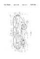
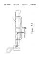
- FIGS. 1A and 1Billustrate the general location of the cushion of the invention in a typical ejection seat.
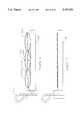
- FIG. 2is a schematic of the components of a system for sensing and varying the pressure in the cushion and for initiating ejection of the seat and rapid release of the gas pressure in the cushion.
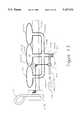
- FIG. 3is a cross-sectional view of the embodiment of the invention employing a release valve and mechanical means for causing rapid release of the pressure of the cushion.
- the cushionis inflated.
- FIG. 4illustrates the mechanism of FIG. 3 with the cushion in a deflated condition.
- FIG. 5is a cross-section of the cushion of FIG. 3 as seen along lines 5--5.
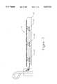
- FIG. 6 and 7are a modified system of FIGS. 3 and 4 for mechanically opening the valves to allow cushion deflation.
- FIG. 8-10illustrate a primer cord routed around the inside of the cushion to explosively rupture the cushion when actuated.
- FIG. 11 and 12illustrate mechanically opened valves that vent the cushion air to a vacuum container to speed deflation.
- FIG. 13 and 14illustrate an ejector arrangement to speed deflation of the cushion.
- an ejection seat 21typically used in aircraft. It comprises a bottom portion 23 on which a person sits and a back portion 25 for supporting the person's back.
- a manually actuated ejection handleis shown at 27 which is actuated by the person setting on the seat for causing the generation of hot gases under pressure by the ejection system depicted at 203 for ejection of the seat from the aircraft.
- the handle 27may be located at different positions than that shown.
- the ejection seat and system for ejecting the seatmay be of the type manufactured by McDonnell-Douglas and identified as ACES II.
- the inflatable cushion or bladder 31 of the inventionis shown located in the bottom structural portion 23 of the seat although a similar cushion could be located in the back structural portion 25 of the seat.
- the cushion 31may be generally square or rectangular as seen in FIG. 5.
- FIG. 1Billustrates, in the isometric view, the general location of the rapid deflation device 201. Also shown is the branch 165 off a typical ejection seat's hot gas system 164 into the rapid deflation device actuation cylinder. Note that the remainder of the hot gas system continues unchanged to other seat components.
- the cushion 31is illustrated in block form.
- the ejection handle 27is shown for actuating the cushion deflation system shown in block form at 33.
- Reference numeral 35depicts the system for actuating the seat ejection system. Pulling of the handle 27 actuates the ejection system 35 (for ejecting the seat 21) and the cushion deflation system 33.
- a source of 41 of air or inert gas under pressurehaving an outlet 43 coupled to a valve 45 for allowing gas to flow into the cushion 31 by way of conduit 47 or to flow out of the cushion 31 by way of conduit 47, valve 45 and outlet 49.
- the conduit 47may be coupled to the cushion 31 on one side as shown in FIG. 3, 5, 6, 8, 11, and 13.
- a pressure sensor 51is coupled to the cushion 31 by way of conduit 53 to monitor the pressure difference between ambient air pressure and the pressure in the cushion 31.
- Reference numeral 55illustrates leads coupled between the sensor 51 and the valve 45. In FIG. 2, the power source for the valve 45 and sensor 51 is not illustrated.
- the inflation pressure of the cushion 31will be maintained at some value corresponding to a predetermined pressure differential between the cushion and the local environment outside of the cushion.
- the differential pressure in the cushion 31may be maintained at a value of 5 p.s.i.
- the sensor 51monitors that pressure difference. When the sensor 51 detects too great a change in that pressure difference from its predetermined value, it causes operation of the valve 45 as follows. If the pressure differential varies to the high side of the preset value, the valve 45 will open to allow flow of gas pressure from the cushion 31 to outlet 49 by way of the conduit 47 and the valve 45. If the pressure differential varies to the low side, the valve 45 will open to allow gas pressure to flow into the cushion 31 from the source 41 by way of outlet 43, valve 45 and conduit 47.
- the specified pressure differentialwill be increased as a function of the magnitude of the acceleration being experienced.
- One purpose of the increaseis to keep the seat occupant in the same location in his local environment as he is during unaccelerated flight.
- Another purposeis to keep the cushion from compressing to the point where the occupant feels, under pressure of his body, the hard surface of the seat.
- the amount and scheduling of that pressure increasemay be determined by conventional engineering practice including but not limited to analysis, computer simulation, centrifuge, or flight test.
- the pressure sensor 51will have circuitry, computing devices, mechanical devices or data monitoring capability that will allow it to control the pressure differential during all phases of flight.
- the circuitis represented by the control and feedback loop 55F.
- a different mode of operationcomes into effect when the ejection sequence is initiated. Pulling of the ejection handle 27 starts the sequence of events typical of present ejection seats.
- the cushion deflation systemdeflates the cushion 31 sufficiently prior to movement of the seat up the rails of the ejection system to prevent injury to the occupant.
- a typical ejection sequencedemands that the cushion be fully deflated approximately 0.1 seconds after the event is initiated.
- the inflatable cushion 31is formed of three separate bladders 31A, 31B, and 31B connected together and supported on a frame 81 which is formed of walls 83, 85, 87, and 89 with an opening 91 extending therethrough.
- the cushion 31may generally rectangular or square as shown in FIG. 5.
- the interiors of the bladders 31A, 31B, and 31Care in fluid communication with each other by small tubular openings 31T.
- the frame 81is part of the seat structure.
- the frame 81is generally rectangular or square as seen in plane 81A--81A and conforms generally to the shape of the cushion 31 as shown in FIG. 5.
- the three bladders 31A, 31B, and 31Chave three outlets 31AO, 31BO, and 31CO which extend through three openings 83A, 83B, and 83C of the wall 83. It is estimated that, in practice, the openings 31AO, 31BO, and 31CO should be about one inch in diameter. It is also estimated that between five and ten such openings are required to achieve the desired deflation rate. Nine such openings are shown in FIG. 5. Three valve numbers 101, 103, and 105 are employed to open and close the three outlets 31AO, 31BO, and 31CO respectively.
- the valve members 101, 103, and 105are pivotally coupled to structure of the frame 81 by pins 101A, 103A, and 105A respectively.
- valve members 101, 103, and 105are pivotally coupled to a rod 107 by pins 101B, 103B, and 105B respectively.
- the rod 107has a projection 109 extending therefrom.
- Two reels 111 and 113are rotatably coupled to tabs 111T and 113T which are connected to wall 87 and two reels 115 and 117 are rotatably coupled to tabs 115T and 117T which are connected to wall 89.
- Slotsare provided in walls 83, 87, 85 and in walls 83, 89, and 85 to allow reels 111, 113 and 115, 117 to rotate.
- Bracket 121rotatably supports a lever 125.
- Bracket 123has three projections 123A, 123B and 123C. Projections 123A and 123B support grooved rollers 131 and 133 for rotation. Projection 123C supports a grooved reel 135 and a gear 137 fixedly connected to reel 135 for rotation.
- a rack member 141is provided having teeth 143 on one side which mesh with the teeth 137T of the gear 137. The other side of the rack 141 fits in the grooves of the rollers 131 and 133.
- a projection 145extends from the other side of the rack 141 for engaging and tripping the lever 125 when the rack 141 is actuated.
- the rear end of the rack 141has a piston 151 which slides in a cylinder 153 which is fixedly connected to the wall 85 of the frame 81 by a bracket 155.
- the cylinder portion 153B behind the piston 151is in fluid communication with a cylinder 157 in which is located a pyrotechnic cartridge 159 and a firing pin 161.
- the rear end of the pin 161has a piston 163 which slides in a cylinder 165 which is coupled to the high pressure gas from the existing ejection seat initiation hardware.
- a flexible strap 181 or webbinghas one end 181A connected in the groove of the reel 135 from which it extends to and fits in the grooves of reels 117 and 115, around the inflated cushion 31; in the grooves of the reels 111 and 113; and then to the reel 135 where its other end 181B is connected in the groove of the reel 135.
- the strapmay be of moderate width, i.e. 4 inches, and only located at the back of the cushion. The placement is chosen to insure cushion deflation under the bony prominences of the typical pilot's posterior. Such a location would quickly get the pilot's skeletal structure in close contact with the seat base.
- Another embodimentmay have a strap or straps pulling on a larger piece of material stretched over the entire cushion. Such a design would cause uniform deflation of the entire cushion.
- the end 125A of the lever 125engages the projection 109 of the rod 107 and the end 125B of the lever 125 engages the projection 141 and holds the valves 101, 103, and 105 in their closed positions closing the outlets 31AO, 31BO, and 31CO of the bladders 31A, 31B and 31C maintaining the bladders inflated.
- Dotted line 201represents an enclosure that will enclose the apparatus of FIGS. 3, 4 and 5. Slots will be employed in the enclosure to allow free passage of the strap 181.
- FIGS. 3, 4 and 5Although not shown in FIGS. 3, 4 and 5, the other components of FIG. 2 including source 41, valve 45 and sensor 51 are all employed in the system of FIGS. 3, 4 and 5 in the same manner as described and shown in connection with FIG. 2.
- FIGS. 6-14the reels 111, 113, 115, 117, the strap 181, the rack 141 and gear 137 and components 153, 157, 159, 161, and 163 are not employed.
- reference numerals that are the same as those of FIGS. 1-6identify the same components.
- the system of FIGS. 2will be used in the embodiments of FIGS. 6-14.
- a cord 215is attached to the rod 107 and to the handle 27 and extends around a rotatable reel 217.
- the rod 107is pulled to the left as shown in FIGS. 6 and 7 moving the valves 101, 103, and 105 to open positions to allow the compressed gas to flow out of openings 31AO, 31BO, and 31CO to deflate the bladders 31A, 31B, and 31C of the cushion 31.
- member 221is an explosive primer cord coupled to a detonating device 223.
- the cord 221extends through the bladders 31A, 31B, and 31C of the cushion 31.
- the device 223actuates the primer cord 221 which ruptures the cushion 31, instantly releasing the compressed gas therein.
- member 233is a vacuum container coupled to outlets 31AO, 31BO, and 31CO by way of conduits 233A, 233B, and 233C.
- Valves 235A, 235B, and 235Care located in conduits 233A, 233B, and 233C respectively and are held in closed positions by a rod 237 which extends through the three conduits 233A, 233B, and 233C.
- Cord 215is attached to the rod 237 and to the handle 27 and extends around a rotatable reel 217.
- the rod 237When the handle 27 is pulled, the rod 237 is moved to open the valves 235A, 235B, and 235C to release the pressurized gas from the cushion 31 into the conduits 233A, 233B, and 233C.
- the vacuum of the container 233speeds deflation of the cushion 31.
- the three conduits 233A, 233B, and 233Care coupled to the outlets of the three bladders 31A, 31B, and 31C and to a common conduit 233D which has a friction fit valve 234 located in outlet end 233DO.
- the low pressure in the cushioni.e. less than 5 p.s.i. cannot dislodge the valve 234.
- a high pressure gas source 166has a conduit 166C coupled to a conduit 167 which in turn is coupled to a nozzle 169 located in the conduit 233D whose outlet is directed toward the outlet of the conduit 233D.
- a valve 241normally closes the conduit 167.
- a cord 215is coupled to the valve 241 and to the handle 27 and extends around rotatable reels 217A and 217B.
- the cord 215opens the valve 241 and allows the pressurized gas from source 166 to flow through the nozzle 169 to blow the valve 234 out of the outlet 233DO.
- the high pressure gas flowing from the nozzle 169increases the rate at which the cushion 31 is deflated.
- the relative pressure from source 166may be i.e. 20 p.s.i. much higher than the pressure within the cushion 31.
Landscapes
- Engineering & Computer Science (AREA)
- Aviation & Aerospace Engineering (AREA)
- Business, Economics & Management (AREA)
- Emergency Management (AREA)
- Seats For Vehicles (AREA)
Abstract
Description
1. Field of the Invention.
The invention relate to a rapid deflation system for a pneumatic seat cushion useful in aircraft.
2. Description of the Prior Art
The seats of many tactical aircraft are uncomfortable to the pilots or crewmembers even for short missions. Because of the firmness of the cushions used in the present seating systems, there is a considerable, sometimes partially debilitating amount of discomfort experienced by those persons required to use the seats. The discomfort grows with time and with the manner in which the seat is used. For example, if the seat is in a maneuvering aircraft, the user feels higher pressures on the body/seat contact points during so called "positive `g`" maneuvers that can result in greater discomfort. A cushion that is less firm would decrease the discomfort, but at the greater risk of serious injury during ejection.
For an ejection-seat-equipped aircraft, the risk of sitting on a soft cushion is enormous. During an ejection sequence while sitting on the very firm standard issue seat cushion, the crewmember and seat accelerate out of the aircraft as one. That acceleration is carefully tailored to generate the maximum force that a pilot can reasonably tolerate. If that crewmember were to add a soft cushion between himself and the seat, the stage is set for disaster. Should an ejection sequence be initiated while on the soft cushion, the crewmember would at first remain stationary while the seat accelerated and the cushion compressed. Eventually the now fast moving seat would come crashing into the crewmember's posterior with great force likely causing serious spinal injury. Present seating systems avoid that impact by making the cushions so thin and firm that the occupant accelerates practically as one with the seat.
In order to eradicate the problems associated with present seating systems, it is an object of the invention to employ a pneumatic cushion whose inflation pressure is varied to suit the comfort and safety needs of the occupant. In accordance with one aspect of the invention, during normal operation, the differential between the seat cushion inflation pressure and the ambient pressure of the confines in which the seat is installed, is maintained at a value specified to maximize the comfort and efficiency of the occupant. During times of increased acceleration associated with maneuvering flight, that specified differential may be increased as required to maintain the same location of the occupant relative to his local environment. That is an important point in that it keeps the pilot in the best position to see his instruments and reach his controls. That increase in pressure difference may also serve to prevent the compression of the cushion and contact of the occupant's body with the hard surface of the seat thus avoiding discomfort. This function is similar to the operation of the so called "G-suits" worn by many military pilots. During the ejection sequence, the cushion is caused to rapidly deflate to allow the occupant's body to come in close contact with the hard surface of the seat. That contact, occurring before the seat starts moving, will allow safe transmittal of the ejection acceleration to the occupant's body.
Thus the invention increases the comfort of personnel required to sit or recline for relatively long periods of time in ejection seats or capsules, and provides a safe seating surface for ejection.
In accordance with the invention, there is provided a seat for supporting a person in a vehicle subject to high acceleration forces comprising seat structure for supporting a person; an inflatable cushion coupled to said seat structure in a position for bearing at least a part of the force exerted by the person when supported by said seat structure; a source of gas under pressure for inflating said cushion; control means including pressure sensing means and valve means coupled to said cushion and to said source for maintaining the pressure of the gas in said cushion generally at a given level; and pressure release means independent of said control means for rapidly deflating said cushion to allow the force exerted by the person supported by said seat structure, when high acceleration forces are encountered, to be born primarily by said seat structure.
In accordance with a further aspect of the invention, said pressure release means comprises an outlet coupled to said cushion, a pressure release valve coupled to said outlet for releasing the gas pressure in said cushion when opened, and apparatus for opening said pressure release valve.
In a further aspect, there is provided mechanical compression means for compressing said cushion when said pressure release valve is opened, and means for actuating said compression means when said pressure release valve is opened for compressing said cushion for increasing the rate at which the gas pressure in said cushion is released.
In the embodiment disclosed, the mechanical compression means comprises a flexible strap which compresses said cushion when said pressure release valve is opened.
FIGS. 1A and 1B illustrate the general location of the cushion of the invention in a typical ejection seat.
FIG. 2 is a schematic of the components of a system for sensing and varying the pressure in the cushion and for initiating ejection of the seat and rapid release of the gas pressure in the cushion.
FIG. 3 is a cross-sectional view of the embodiment of the invention employing a release valve and mechanical means for causing rapid release of the pressure of the cushion. In FIG. 3, the cushion is inflated.
FIG. 4 illustrates the mechanism of FIG. 3 with the cushion in a deflated condition.
FIG. 5 is a cross-section of the cushion of FIG. 3 as seen alonglines 5--5.
FIG. 6 and 7 are a modified system of FIGS. 3 and 4 for mechanically opening the valves to allow cushion deflation.
FIG. 8-10 illustrate a primer cord routed around the inside of the cushion to explosively rupture the cushion when actuated.
FIG. 11 and 12 illustrate mechanically opened valves that vent the cushion air to a vacuum container to speed deflation.
FIG. 13 and 14 illustrate an ejector arrangement to speed deflation of the cushion.
Referring now to FIGS. 1A and 1B, there is illustrated anejection seat 21 typically used in aircraft. It comprises abottom portion 23 on which a person sits and aback portion 25 for supporting the person's back. A manually actuated ejection handle is shown at 27 which is actuated by the person setting on the seat for causing the generation of hot gases under pressure by the ejection system depicted at 203 for ejection of the seat from the aircraft. Thehandle 27 may be located at different positions than that shown. The ejection seat and system for ejecting the seat may be of the type manufactured by McDonnell-Douglas and identified as ACES II.
The inflatable cushion orbladder 31 of the invention is shown located in the bottomstructural portion 23 of the seat although a similar cushion could be located in the backstructural portion 25 of the seat. Thecushion 31 may be generally square or rectangular as seen in FIG. 5.
FIG. 1B illustrates, in the isometric view, the general location of therapid deflation device 201. Also shown is thebranch 165 off a typical ejection seat'shot gas system 164 into the rapid deflation device actuation cylinder. Note that the remainder of the hot gas system continues unchanged to other seat components.
Referring to FIG. 2, thecushion 31 is illustrated in block form. Theejection handle 27 is shown for actuating the cushion deflation system shown in block form at 33.Reference numeral 35 depicts the system for actuating the seat ejection system. Pulling of thehandle 27 actuates the ejection system 35 (for ejecting the seat 21) and thecushion deflation system 33.
Also shown is a source of 41 of air or inert gas under pressure having anoutlet 43 coupled to avalve 45 for allowing gas to flow into thecushion 31 by way ofconduit 47 or to flow out of thecushion 31 by way ofconduit 47,valve 45 andoutlet 49. Theconduit 47 may be coupled to thecushion 31 on one side as shown in FIG. 3, 5, 6, 8, 11, and 13.
Apressure sensor 51 is coupled to thecushion 31 by way ofconduit 53 to monitor the pressure difference between ambient air pressure and the pressure in thecushion 31.Reference numeral 55 illustrates leads coupled between thesensor 51 and thevalve 45. In FIG. 2, the power source for thevalve 45 andsensor 51 is not illustrated.
During routine flight at or near one "g" acceleration in the local vertical direction, the inflation pressure of thecushion 31 will be maintained at some value corresponding to a predetermined pressure differential between the cushion and the local environment outside of the cushion. For example the differential pressure in thecushion 31 may be maintained at a value of 5 p.s.i. Thesensor 51 monitors that pressure difference. When thesensor 51 detects too great a change in that pressure difference from its predetermined value, it causes operation of thevalve 45 as follows. If the pressure differential varies to the high side of the preset value, thevalve 45 will open to allow flow of gas pressure from thecushion 31 tooutlet 49 by way of theconduit 47 and thevalve 45. If the pressure differential varies to the low side, thevalve 45 will open to allow gas pressure to flow into thecushion 31 from thesource 41 by way ofoutlet 43,valve 45 andconduit 47.
During times of maneuvering flight, the specified pressure differential will be increased as a function of the magnitude of the acceleration being experienced. One purpose of the increase is to keep the seat occupant in the same location in his local environment as he is during unaccelerated flight. Another purpose is to keep the cushion from compressing to the point where the occupant feels, under pressure of his body, the hard surface of the seat. The amount and scheduling of that pressure increase may be determined by conventional engineering practice including but not limited to analysis, computer simulation, centrifuge, or flight test. Thepressure sensor 51 will have circuitry, computing devices, mechanical devices or data monitoring capability that will allow it to control the pressure differential during all phases of flight. The circuit is represented by the control andfeedback loop 55F.
There also may be a separate controller that takes precedence during times of accelerated flight.
A different mode of operation comes into effect when the ejection sequence is initiated. Pulling of the ejection handle 27 starts the sequence of events typical of present ejection seats. The cushion deflation system deflates thecushion 31 sufficiently prior to movement of the seat up the rails of the ejection system to prevent injury to the occupant. A typical ejection sequence demands that the cushion be fully deflated approximately 0.1 seconds after the event is initiated.
Referring now to FIGS. 3 and 4, theinflatable cushion 31 is formed of threeseparate bladders frame 81 which is formed ofwalls opening 91 extending therethrough. Thecushion 31 may generally rectangular or square as shown in FIG. 5. The interiors of thebladders tubular openings 31T. Theframe 81 is part of the seat structure. Theframe 81 is generally rectangular or square as seen in plane 81A--81A and conforms generally to the shape of thecushion 31 as shown in FIG. 5. The threebladders wall 83. It is estimated that, in practice, the openings 31AO, 31BO, and 31CO should be about one inch in diameter. It is also estimated that between five and ten such openings are required to achieve the desired deflation rate. Nine such openings are shown in FIG. 5. Threevalve numbers valve members frame 81 by pins 101A, 103A, and 105A respectively. Inaddition valve members rod 107 bypins 101B, 103B, and 105B respectively. Therod 107 has aprojection 109 extending therefrom.
Tworeels 111 and 113 are rotatably coupled to tabs 111T and 113T which are connected to wall 87 and tworeels tabs 115T and 117T which are connected to wall 89. Slots are provided inwalls walls reels
Secured to the outside ofwall 85 arebrackets Bracket 121 rotatably supports alever 125.Bracket 123 has threeprojections Projections rollers Projection 123C supports agrooved reel 135 and agear 137 fixedly connected to reel 135 for rotation. Arack member 141 is provided havingteeth 143 on one side which mesh with theteeth 137T of thegear 137. The other side of therack 141 fits in the grooves of therollers projection 145 extends from the other side of therack 141 for engaging and tripping thelever 125 when therack 141 is actuated.
The rear end of therack 141 has apiston 151 which slides in acylinder 153 which is fixedly connected to thewall 85 of theframe 81 by abracket 155. Thecylinder portion 153B behind thepiston 151 is in fluid communication with acylinder 157 in which is located apyrotechnic cartridge 159 and afiring pin 161. The rear end of thepin 161 has apiston 163 which slides in acylinder 165 which is coupled to the high pressure gas from the existing ejection seat initiation hardware.
Aflexible strap 181 or webbing has one end 181A connected in the groove of thereel 135 from which it extends to and fits in the grooves ofreels inflated cushion 31; in the grooves of thereels 111 and 113; and then to thereel 135 where its other end 181B is connected in the groove of thereel 135.
In one embodiment the strap may be of moderate width, i.e. 4 inches, and only located at the back of the cushion. The placement is chosen to insure cushion deflation under the bony prominences of the typical pilot's posterior. Such a location would quickly get the pilot's skeletal structure in close contact with the seat base. Another embodiment may have a strap or straps pulling on a larger piece of material stretched over the entire cushion. Such a design would cause uniform deflation of the entire cushion.
In the inflated position of thecushion 131, the end 125A of thelever 125 engages theprojection 109 of therod 107 and theend 125B of thelever 125 engages theprojection 141 and holds thevalves bladders
When thehandle 27 is pulled to actuate the ejection system, high pressure gas flows from the ejection system tocylinder 165 forcing thepiston 163 and itspin 161 into thecartridge 159 causing thecartridge 159 to ignite. This creates very high pressure gas in thecylinder 157 which rapidly causes thepiston 151 and hence therack 141 to move to the right as shown in FIGS. 3 and 4, tripping thelever 125 and allowing thevalves bladders opening 91. At the same time, thereel 135 is rotated clockwise as shown in FIGS. 3 and 4 causing thestrap 181 to be wound around thereel 135 thereby compressing thebladders
Although not shown in FIGS. 3, 4 and 5, the other components of FIG. 2 includingsource 41,valve 45 andsensor 51 are all employed in the system of FIGS. 3, 4 and 5 in the same manner as described and shown in connection with FIG. 2.
Referring now to the embodiments of FIGS. 6-14 thereels strap 181, therack 141 andgear 137 andcomponents
Referring first to the embodiment of FIGS. 6 and 7 acord 215 is attached to therod 107 and to thehandle 27 and extends around arotatable reel 217. When thehandle 27 is pulled, therod 107 is pulled to the left as shown in FIGS. 6 and 7 moving thevalves bladders cushion 31.
Referring to FIGS. 8-10,member 221 is an explosive primer cord coupled to a detonating device 223. Thecord 221 extends through thebladders cushion 31. When thehandle 27 is pulled, the device 223 actuates theprimer cord 221 which ruptures thecushion 31, instantly releasing the compressed gas therein.
Referring to FIGS. 11 and 12member 233 is a vacuum container coupled to outlets 31AO, 31BO, and 31CO by way ofconduits Valves conduits rod 237 which extends through the threeconduits Cord 215 is attached to therod 237 and to thehandle 27 and extends around arotatable reel 217. When thehandle 27 is pulled, therod 237 is moved to open thevalves cushion 31 into theconduits container 233 speeds deflation of thecushion 31.
Referring to FIGS. 13 and 14, the threeconduits bladders common conduit 233D which has a frictionfit valve 234 located in outlet end 233DO. The low pressure in the cushion, i.e. less than 5 p.s.i. cannot dislodge thevalve 234. A highpressure gas source 166 has aconduit 166C coupled to aconduit 167 which in turn is coupled to anozzle 169 located in theconduit 233D whose outlet is directed toward the outlet of theconduit 233D. Avalve 241 normally closes theconduit 167. Acord 215 is coupled to thevalve 241 and to thehandle 27 and extends aroundrotatable reels handle 27 is pulled, thecord 215 opens thevalve 241 and allows the pressurized gas fromsource 166 to flow through thenozzle 169 to blow thevalve 234 out of the outlet 233DO. The high pressure gas flowing from thenozzle 169 increases the rate at which thecushion 31 is deflated. In the embodiment the relative pressure fromsource 166 may be i.e. 20 p.s.i. much higher than the pressure within thecushion 31.
Claims (7)
1. A seat for supporting a person in an aircraft, said seat being of the type adapted to be ejected from the aircraft comprising:
seat structure for supporting a person,
an inflatable cushion coupled to said seat structure in a position for bearing at least a part of the force exerted by the person when supported by said seat structure,
a source of gas under pressure for inflating said cushion,
control means including pressure sensing means and valve means coupled to said cushion and to said source for maintaining the pressure of the gas in said cushion generally at a given level,
pressure release means independent of said control means for rapidly deflating said cushion to allow the force exerted by the person supported by said seat structure, when high acceleration forces are encountered upon ejection of the seat structure, to be born primarily by said seat structure.
2. A seat for supporting a person in a vehicle subject to high acceleration forces, comprising:
seat structure for supporting a person,
an inflatable cushion coupled to said seat structure in a position for beating at least a part of the force exerted by the person when supported by said seat structure,
a source of gas under pressure for inflating said cushion,
control means including pressure sensing means and valve means coupled to said cushion and to said source for maintaining the pressure of the gas in said cushion generally at a given level, and
pressure release means independent of said control means for rapidly deflating said cushion to allow the force exerted by the person supported by said seat structure, when high acceleration forces are encountered, to be born primarily by said seat structure,
said pressure release means comprises:
at least one outlet coupled to said cushion,
a pressure release valve coupled to said outlet for releasing the gas pressure in said cushion when opened, and
a manually actuated apparatus for opening said pressure release valve.
3. The seat of claim 2 comprising mechanical compression means for compressing said cushion when said pressure release valve is opened, and means for actuating said mechanical compression means when said pressure release valve is opened for compressing said cushion for increasing the rate at which the gas pressure in said cushion is released.
4. The seat of claim 3 wherein said mechanical compression means comprises a flexible strap coupled to one side of said cushion and to said seat and actuating means for forcing said strap against said one side of said cushion when said pressure release valve is opened for increasing the rate at which the gas pressure in said cushion is released.
5. The seat of claim 2, comprising:
a container coupled to said release valve and having a pressure lower than that of said cushion for increasing the rate at which the gas pressure is released from said cushion when said release valve is opened.
6. A seat for supporting a person in a vehicle subject to high acceleration forces, comprising:
seat structure for supporting a person,
an inflatable cushion coupled to said seat structure in a position for bearing at least a part of the force exerted by the person when supported by said seat structure,
a source of gas under pressure for inflating said cushion,
control means including pressure sensing means and valve means coupled to said cushion and to said source for maintaining the pressure of the gas in said cushion generally at a given level, and
pressure release means independent of said control means for rapidly deflating said cushion to allow the force exerted by the person supported by said seat structure, when high acceleration forces are encountered, to be born primarily by said seat structure,
said pressure release means comprises explosive means coupled to said cushion for severing said cushion when said explosive means is exploded, and
means for exploding said explosive means.
7. A seat for supporting a person in a vehicle subject to high acceleration forces, comprising:
seat structure for supporting a person,
an inflatable cushion coupled to said seat structure in a position for beating at least a part of the force exerted by the person when supported by said seat structure,
a source of gas under pressure for inflating said cushion.
control means including pressure sensing means and valve means coupled to said cushion and to said source for maintaining the pressure of the gas in said cushion generally at a given level, and
pressure release means independent of said control means for rapidly deflating said cushion to allow the force exerted by the person supported by said seat structure, when high acceleration forces are encountered, to be born primarily by said seat structure,
said pressure release means comprises:
at least one outlet coupled to said cushion,
an outlet valve for normally closing said outlet,
said outlet valve being adapted to be actuated for opening said outlet,
a source of high gas pressure,
a nozzle coupled to said source by way of a conduit and to said outlet for flowing high pressure gas from said source of high gas pressure out of said outlet when said outlet is open,
a normally closed control valve coupled to said conduit,
a manually actuated apparatus for opening said control valve for releasing the high gas pressure from said source of high gas pressure for flow to said nozzle and out of said outlet when said outlet is open for increasing the rate at which the gas pressure in said cushion is released.
Priority Applications (1)
| Application Number | Priority Date | Filing Date | Title |
|---|---|---|---|
| US08/221,854US5427331A (en) | 1994-04-01 | 1994-04-01 | Rapid deflation system for pneumatic seat cushion |
Applications Claiming Priority (1)
| Application Number | Priority Date | Filing Date | Title |
|---|---|---|---|
| US08/221,854US5427331A (en) | 1994-04-01 | 1994-04-01 | Rapid deflation system for pneumatic seat cushion |
Publications (1)
| Publication Number | Publication Date |
|---|---|
| US5427331Atrue US5427331A (en) | 1995-06-27 |
Family
ID=22829678
Family Applications (1)
| Application Number | Title | Priority Date | Filing Date |
|---|---|---|---|
| US08/221,854Expired - Fee RelatedUS5427331A (en) | 1994-04-01 | 1994-04-01 | Rapid deflation system for pneumatic seat cushion |
Country Status (1)
| Country | Link |
|---|---|
| US (1) | US5427331A (en) |
Cited By (25)
| Publication number | Priority date | Publication date | Assignee | Title |
|---|---|---|---|---|
| US5903941A (en)* | 1994-11-01 | 1999-05-18 | Select Comfort Corporation | Air control system for an air bed |
| US5975568A (en)* | 1998-04-01 | 1999-11-02 | American Components, Inc. | Sensor pad for controlling airbag deployment and associated support |
| WO2000013945A1 (en)* | 1998-09-03 | 2000-03-16 | American Components, Inc. | Sensor pad for controlling airbag deployment and associated support |
| US6045155A (en)* | 1997-01-16 | 2000-04-04 | Automotive Systems Laboratory, Inc. | Vehicle seat sensor having self-maintaining air bladder |
| US6086097A (en)* | 1998-06-09 | 2000-07-11 | Trw Inc. | Vehicle occupant protection apparatus |
| US6119727A (en)* | 1998-06-16 | 2000-09-19 | Gt Development Corporation | Pneumatic seat valve having a rapid exhaust mode |
| US6203105B1 (en) | 1999-08-20 | 2001-03-20 | Mccord Winn Textron Inc. | Vehicle impact responsive multiple bladder seating and headrest system and method |
| US6234500B1 (en)* | 1997-10-31 | 2001-05-22 | Steven E. Aufrance | Pneumatic device for adjusting wheel camber |
| US6286861B1 (en) | 1996-12-19 | 2001-09-11 | Automotive Systems Laboratory, Inc. | Seat weight sensor |
| US6668405B1 (en) | 2001-01-09 | 2003-12-30 | Aquila Corporation Of Wisconsin | Variable pressure relief inflated cushion |
| US6674024B2 (en) | 1996-12-19 | 2004-01-06 | Automotive Systems Laboratory, Inc | Seat weight sensor |
| US20040069071A1 (en)* | 2001-11-19 | 2004-04-15 | Speckhart Frank H. | Sensor pad for controlling airbag deployment and associated support |
| US6848135B1 (en) | 2003-01-29 | 2005-02-01 | Aquila Corporation Of Wisconsin | Inflation level monitoring system for inflatable cushions |
| US20050184496A1 (en)* | 2003-10-03 | 2005-08-25 | Speckhart Frank H. | Sensor pad for controlling airbag deployment and associated support |
| US20050230951A1 (en)* | 2002-12-20 | 2005-10-20 | Volvo Lastvagnar Ab | Shock-absorbing occupant protection |
| US20060033312A1 (en)* | 2004-08-13 | 2006-02-16 | William Barvosa-Carter | Reversibly deployable energy absorbing assembly and methods for operating the same |
| CN100375702C (en)* | 2004-09-21 | 2008-03-19 | 武汉理工大学 | Marine rescue chair system |
| US7455355B1 (en) | 2007-01-19 | 2008-11-25 | Aquilla Corporation Of Wisconsin | User adjustable motorcycle seat cushion with independently inflatable and deflatable ischial support cell and gluteous support cell |
| US8033600B2 (en) | 2007-05-29 | 2011-10-11 | Ergoair, Inc. | Seat system with shock- and vibration-reducing bladders |
| US8181292B1 (en) | 2009-09-15 | 2012-05-22 | The United States Of America As Represented By The Secretary Of The Air Force | Seat cushion |
| US9283875B1 (en) | 2009-09-15 | 2016-03-15 | The United States Of America As Represented By The Secretary Of The Airforce | Seat cushion |
| US11117537B2 (en)* | 2019-03-19 | 2021-09-14 | Faurecia Automotive Seating, Llc | Backrest of a vehicle seat |
| US20210309380A1 (en)* | 2020-04-07 | 2021-10-07 | Ami Industries, Inc. | Lateral support system for ejection seat |
| US11540959B1 (en) | 2019-07-11 | 2023-01-03 | Steven Paul Kohlman | Therapy seat cushion with interspersed selectively inflatable load bearing cells and off loading cushioning cells |
| US11613366B2 (en)* | 2020-04-07 | 2023-03-28 | Ami Industries, Inc. | Lumbar support systems for ejection seat |
Citations (8)
| Publication number | Priority date | Publication date | Assignee | Title |
|---|---|---|---|---|
| US2981317A (en)* | 1957-11-22 | 1961-04-25 | Chance Vought Corp | Shock absorbing safety seat |
| GB941072A (en)* | 1960-10-24 | 1963-11-06 | Gq Parachute Comp Ltd | Improvements in or relating to seats upon aircraft |
| US3192541A (en)* | 1962-03-19 | 1965-07-06 | Boyd S Moore | Contourable pneumatic cushions |
| US3192540A (en)* | 1962-01-22 | 1965-07-06 | Richard E Swank | Adjustable pneumatic support |
| FR2250327A5 (en)* | 1973-10-31 | 1975-05-30 | Rayne Andre | Two part safety seat for an automobile - has cushions which deflate upon a crash so passenger falls and knees rise |
| US3966146A (en)* | 1975-03-10 | 1976-06-29 | The United States Of America As Represented By The Secretary Of The Air Force | Air bladder seat cushion for high acceleration cockpit |
| US4634083A (en)* | 1984-09-11 | 1987-01-06 | Cae Electronics Ltd. | Helicopter seat isolation system |
| US4834322A (en)* | 1986-05-20 | 1989-05-30 | Rockwell International Corporation | High "g" protection system |
- 1994
- 1994-04-01USUS08/221,854patent/US5427331A/ennot_activeExpired - Fee Related
Patent Citations (8)
| Publication number | Priority date | Publication date | Assignee | Title |
|---|---|---|---|---|
| US2981317A (en)* | 1957-11-22 | 1961-04-25 | Chance Vought Corp | Shock absorbing safety seat |
| GB941072A (en)* | 1960-10-24 | 1963-11-06 | Gq Parachute Comp Ltd | Improvements in or relating to seats upon aircraft |
| US3192540A (en)* | 1962-01-22 | 1965-07-06 | Richard E Swank | Adjustable pneumatic support |
| US3192541A (en)* | 1962-03-19 | 1965-07-06 | Boyd S Moore | Contourable pneumatic cushions |
| FR2250327A5 (en)* | 1973-10-31 | 1975-05-30 | Rayne Andre | Two part safety seat for an automobile - has cushions which deflate upon a crash so passenger falls and knees rise |
| US3966146A (en)* | 1975-03-10 | 1976-06-29 | The United States Of America As Represented By The Secretary Of The Air Force | Air bladder seat cushion for high acceleration cockpit |
| US4634083A (en)* | 1984-09-11 | 1987-01-06 | Cae Electronics Ltd. | Helicopter seat isolation system |
| US4834322A (en)* | 1986-05-20 | 1989-05-30 | Rockwell International Corporation | High "g" protection system |
Cited By (35)
| Publication number | Priority date | Publication date | Assignee | Title |
|---|---|---|---|---|
| US6037723A (en)* | 1994-11-01 | 2000-03-14 | Select Comfort Corporation | Air control system for an air bed |
| US5903941A (en)* | 1994-11-01 | 1999-05-18 | Select Comfort Corporation | Air control system for an air bed |
| US6674024B2 (en) | 1996-12-19 | 2004-01-06 | Automotive Systems Laboratory, Inc | Seat weight sensor |
| US6286861B1 (en) | 1996-12-19 | 2001-09-11 | Automotive Systems Laboratory, Inc. | Seat weight sensor |
| US6045155A (en)* | 1997-01-16 | 2000-04-04 | Automotive Systems Laboratory, Inc. | Vehicle seat sensor having self-maintaining air bladder |
| US6234500B1 (en)* | 1997-10-31 | 2001-05-22 | Steven E. Aufrance | Pneumatic device for adjusting wheel camber |
| US5975568A (en)* | 1998-04-01 | 1999-11-02 | American Components, Inc. | Sensor pad for controlling airbag deployment and associated support |
| US20060137477A1 (en)* | 1998-04-01 | 2006-06-29 | Speckhart Frank H | Sensor pad for controlling airbag deployment and associated support |
| US7237443B2 (en) | 1998-04-01 | 2007-07-03 | Methode Electronics, Inc. | Sensor pad for controlling airbag deployment and associated support |
| US8151654B2 (en) | 1998-04-01 | 2012-04-10 | Methode Electronics, Inc. | Sensor pad for controlling airbag deployment and associated support |
| US6086097A (en)* | 1998-06-09 | 2000-07-11 | Trw Inc. | Vehicle occupant protection apparatus |
| US6119727A (en)* | 1998-06-16 | 2000-09-19 | Gt Development Corporation | Pneumatic seat valve having a rapid exhaust mode |
| WO2000013945A1 (en)* | 1998-09-03 | 2000-03-16 | American Components, Inc. | Sensor pad for controlling airbag deployment and associated support |
| US6203105B1 (en) | 1999-08-20 | 2001-03-20 | Mccord Winn Textron Inc. | Vehicle impact responsive multiple bladder seating and headrest system and method |
| US6668405B1 (en) | 2001-01-09 | 2003-12-30 | Aquila Corporation Of Wisconsin | Variable pressure relief inflated cushion |
| US20040069071A1 (en)* | 2001-11-19 | 2004-04-15 | Speckhart Frank H. | Sensor pad for controlling airbag deployment and associated support |
| US20050230951A1 (en)* | 2002-12-20 | 2005-10-20 | Volvo Lastvagnar Ab | Shock-absorbing occupant protection |
| US7500695B2 (en)* | 2002-12-20 | 2009-03-10 | Volvo Lastvagnar Ab | Shock-absorbing occupant protection |
| US6848135B1 (en) | 2003-01-29 | 2005-02-01 | Aquila Corporation Of Wisconsin | Inflation level monitoring system for inflatable cushions |
| US20050184496A1 (en)* | 2003-10-03 | 2005-08-25 | Speckhart Frank H. | Sensor pad for controlling airbag deployment and associated support |
| US20060033312A1 (en)* | 2004-08-13 | 2006-02-16 | William Barvosa-Carter | Reversibly deployable energy absorbing assembly and methods for operating the same |
| US20080191454A1 (en)* | 2004-08-13 | 2008-08-14 | General Motors Corporation | Reversibly deployable energy absorbing assembly and methods for operating the same |
| US7264271B2 (en) | 2004-08-13 | 2007-09-04 | General Motors Corporation | Reversibly deployable energy absorbing assembly and methods for operating the same |
| CN100375702C (en)* | 2004-09-21 | 2008-03-19 | 武汉理工大学 | Marine rescue chair system |
| US7455355B1 (en) | 2007-01-19 | 2008-11-25 | Aquilla Corporation Of Wisconsin | User adjustable motorcycle seat cushion with independently inflatable and deflatable ischial support cell and gluteous support cell |
| US8033600B2 (en) | 2007-05-29 | 2011-10-11 | Ergoair, Inc. | Seat system with shock- and vibration-reducing bladders |
| US9283875B1 (en) | 2009-09-15 | 2016-03-15 | The United States Of America As Represented By The Secretary Of The Airforce | Seat cushion |
| US8181292B1 (en) | 2009-09-15 | 2012-05-22 | The United States Of America As Represented By The Secretary Of The Air Force | Seat cushion |
| US11117537B2 (en)* | 2019-03-19 | 2021-09-14 | Faurecia Automotive Seating, Llc | Backrest of a vehicle seat |
| US11540959B1 (en) | 2019-07-11 | 2023-01-03 | Steven Paul Kohlman | Therapy seat cushion with interspersed selectively inflatable load bearing cells and off loading cushioning cells |
| US20210309380A1 (en)* | 2020-04-07 | 2021-10-07 | Ami Industries, Inc. | Lateral support system for ejection seat |
| US11608182B2 (en)* | 2020-04-07 | 2023-03-21 | Ami Industries, Inc. | Lateral support system for ejection seat |
| US11613366B2 (en)* | 2020-04-07 | 2023-03-28 | Ami Industries, Inc. | Lumbar support systems for ejection seat |
| GB2627881A (en)* | 2020-04-07 | 2024-09-04 | Ami Ind Inc | Lateral support system for ejection seat |
| GB2627881B (en)* | 2020-04-07 | 2025-02-12 | Ami Ind Inc | Lateral support system for ejection seat |
Similar Documents
| Publication | Publication Date | Title |
|---|---|---|
| US5427331A (en) | Rapid deflation system for pneumatic seat cushion | |
| JPH02303998A (en) | Helmet | |
| US6607166B1 (en) | Inflatable flying body for the rescue descent of a person | |
| EP3145594B1 (en) | Breathing system and seat for aircraft crew member or passenger | |
| US6315245B1 (en) | Ejection seat with blast protection system | |
| JPH02114097A (en) | Side head inhibitor and head inhibiting method | |
| JP3960394B2 (en) | Thin film airbag | |
| CA2702547C (en) | Crash attenuation system for aircraft | |
| US5954052A (en) | Safety stowage apparatus for crew oxygen masks | |
| CA2821326C (en) | Active vent and re-inflation system for a crash attenuation airbag | |
| EP1759993A2 (en) | Aircraft evacuation slide with primary gas relief valve | |
| JP2567200B2 (en) | Airborne flying evacuation equipment | |
| JP2009514740A (en) | Aircraft collision mitigation system | |
| JPH07136273A (en) | Breathing apparatus | |
| WO2001000456A9 (en) | Inflatable l shaped airbag for an inflatable restraint system | |
| EP0351568A2 (en) | Adaptive torso restraint system | |
| US3179360A (en) | Inflatable personnel restraint system for advanced flight vehicles | |
| US4826247A (en) | System for assisting a fighter pilot in checking the six-o'clock position | |
| US3372893A (en) | Air to ground descent means | |
| WO1986003130A1 (en) | Aircraft safety cushion assemblies | |
| US7789085B2 (en) | Presentation arrangement for an oxygen mask or a pull flag | |
| US4627587A (en) | Airplane seat with convertible flotation-cushion system | |
| JP4014015B2 (en) | Emergency escape device | |
| US6296204B1 (en) | Restraint system for a flight helmet | |
| CN110481789B (en) | Aircraft air cushion with limited deployment volume |
Legal Events
| Date | Code | Title | Description |
|---|---|---|---|
| AS | Assignment | Owner name:LOCKHEED CORPORATION, TEXAS Free format text:ASSIGNMENT OF ASSIGNORS INTEREST;ASSIGNOR:STROUD, RONALD LEE;REEL/FRAME:006951/0612 Effective date:19940331 | |
| FEPP | Fee payment procedure | Free format text:PAYOR NUMBER ASSIGNED (ORIGINAL EVENT CODE: ASPN); ENTITY STATUS OF PATENT OWNER: LARGE ENTITY | |
| AS | Assignment | Owner name:LOCKHEED MARTIN CORPORATION, MARYLAND Free format text:MERGER;ASSIGNOR:LOCKHEED CORPORATION;REEL/FRAME:009430/0915 Effective date:19960128 | |
| FPAY | Fee payment | Year of fee payment:4 | |
| REMI | Maintenance fee reminder mailed | ||
| FPAY | Fee payment | Year of fee payment:8 | |
| REMI | Maintenance fee reminder mailed | ||
| LAPS | Lapse for failure to pay maintenance fees | ||
| STCH | Information on status: patent discontinuation | Free format text:PATENT EXPIRED DUE TO NONPAYMENT OF MAINTENANCE FEES UNDER 37 CFR 1.362 | |
| FP | Lapsed due to failure to pay maintenance fee | Effective date:20070627 |