US5426685A - Stereotactic mammography system imaging - Google Patents
Stereotactic mammography system imagingDownload PDFInfo
- Publication number
- US5426685A US5426685AUS08/185,690US18569094AUS5426685AUS 5426685 AUS5426685 AUS 5426685AUS 18569094 AUS18569094 AUS 18569094AUS 5426685 AUS5426685 AUS 5426685A
- Authority
- US
- United States
- Prior art keywords
- arm
- compression
- image
- patient
- ray
- Prior art date
- Legal status (The legal status is an assumption and is not a legal conclusion. Google has not performed a legal analysis and makes no representation as to the accuracy of the status listed.)
- Expired - Lifetime
Links
- 238000003384imaging methodMethods0.000titleclaimsabstractdescription43
- 238000009607mammographyMethods0.000titleabstractdescription23
- NJPPVKZQTLUDBO-UHFFFAOYSA-NnovaluronChemical compoundC1=C(Cl)C(OC(F)(F)C(OC(F)(F)F)F)=CC=C1NC(=O)NC(=O)C1=C(F)C=CC=C1FNJPPVKZQTLUDBO-UHFFFAOYSA-N0.000claimsabstractdescription26
- 230000006835compressionEffects0.000claimsdescription69
- 238000007906compressionMethods0.000claimsdescription69
- OAICVXFJPJFONN-UHFFFAOYSA-NPhosphorusChemical compound[P]OAICVXFJPJFONN-UHFFFAOYSA-N0.000claimsdescription23
- 238000001574biopsyMethods0.000claimsdescription22
- 230000004807localizationEffects0.000claims2
- 210000000481breastAnatomy0.000abstractdescription52
- 230000003902lesionEffects0.000abstractdescription35
- 238000013188needle biopsyMethods0.000abstractdescription11
- 238000003745diagnosisMethods0.000abstractdescription3
- 238000001444catalytic combustion detectionMethods0.000description48
- 239000010408filmSubstances0.000description37
- 102000005962receptorsHuman genes0.000description25
- 108020003175receptorsProteins0.000description25
- 230000003287optical effectEffects0.000description20
- 238000010586diagramMethods0.000description17
- 238000000034methodMethods0.000description17
- 210000001519tissueAnatomy0.000description16
- 230000033001locomotionEffects0.000description12
- 238000012545processingMethods0.000description10
- 230000008901benefitEffects0.000description6
- 238000001914filtrationMethods0.000description6
- 238000010276constructionMethods0.000description4
- 238000006073displacement reactionMethods0.000description4
- 230000001965increasing effectEffects0.000description4
- 239000010409thin filmSubstances0.000description4
- 238000013459approachMethods0.000description3
- 238000000576coating methodMethods0.000description3
- 230000001934delayEffects0.000description3
- 238000011161developmentMethods0.000description3
- 238000011156evaluationMethods0.000description3
- 230000008569processEffects0.000description3
- 230000005855radiationEffects0.000description3
- 238000012800visualizationMethods0.000description3
- 239000000020NitrocelluloseSubstances0.000description2
- 241000208967Polygala cruciataSpecies0.000description2
- VYPSYNLAJGMNEJ-UHFFFAOYSA-NSilicium dioxideChemical compoundO=[Si]=OVYPSYNLAJGMNEJ-UHFFFAOYSA-N0.000description2
- 239000011248coating agentSubstances0.000description2
- 238000004590computer programMethods0.000description2
- 230000006870functionEffects0.000description2
- 208000014674injuryDiseases0.000description2
- 238000003780insertionMethods0.000description2
- 230000037431insertionEffects0.000description2
- 229910052751metalInorganic materials0.000description2
- 239000002184metalSubstances0.000description2
- 229920001220nitrocellulosPolymers0.000description2
- 238000012634optical imagingMethods0.000description2
- 238000001356surgical procedureMethods0.000description2
- 210000000779thoracic wallAnatomy0.000description2
- 238000012546transferMethods0.000description2
- 230000008733traumaEffects0.000description2
- 238000012795verificationMethods0.000description2
- 208000012661DyskinesiaDiseases0.000description1
- 208000015592Involuntary movementsDiseases0.000description1
- 206010038743RestlessnessDiseases0.000description1
- 102100025747Sphingosine 1-phosphate receptor 3Human genes0.000description1
- 101710155457Sphingosine 1-phosphate receptor 3Proteins0.000description1
- YKTSYUJCYHOUJP-UHFFFAOYSA-N[O--].[Al+3].[Al+3].[O-][Si]([O-])([O-])[O-]Chemical compound[O--].[Al+3].[Al+3].[O-][Si]([O-])([O-])[O-]YKTSYUJCYHOUJP-UHFFFAOYSA-N0.000description1
- 230000005856abnormalityEffects0.000description1
- 229910052782aluminiumInorganic materials0.000description1
- XAGFODPZIPBFFR-UHFFFAOYSA-NaluminiumChemical compound[Al]XAGFODPZIPBFFR-UHFFFAOYSA-N0.000description1
- 229940024548aluminum oxideDrugs0.000description1
- 238000000429assemblyMethods0.000description1
- 230000005540biological transmissionEffects0.000description1
- 230000000903blocking effectEffects0.000description1
- 238000004364calculation methodMethods0.000description1
- 230000015556catabolic processEffects0.000description1
- 239000004020conductorSubstances0.000description1
- 238000012790confirmationMethods0.000description1
- 238000006731degradation reactionMethods0.000description1
- 238000002059diagnostic imagingMethods0.000description1
- 230000004069differentiationEffects0.000description1
- 238000009792diffusion processMethods0.000description1
- 230000003028elevating effectEffects0.000description1
- 210000004209hairAnatomy0.000description1
- 238000005286illuminationMethods0.000description1
- 230000006872improvementEffects0.000description1
- 230000001939inductive effectEffects0.000description1
- 230000002452interceptive effectEffects0.000description1
- 230000009545invasionEffects0.000description1
- 238000013507mappingMethods0.000description1
- 239000000463materialSubstances0.000description1
- 239000011159matrix materialSubstances0.000description1
- 238000005259measurementMethods0.000description1
- 230000007246mechanismEffects0.000description1
- 239000012528membraneSubstances0.000description1
- 239000007769metal materialSubstances0.000description1
- 210000003205muscleAnatomy0.000description1
- 230000017311musculoskeletal movement, spinal reflex actionEffects0.000description1
- 238000009304pastoral farmingMethods0.000description1
- 238000010244region-of-interest analysisMethods0.000description1
- 231100000241scarToxicity0.000description1
- 230000035945sensitivityEffects0.000description1
- 235000012239silicon dioxideNutrition0.000description1
- 239000000377silicon dioxideSubstances0.000description1
Images


Classifications
- A—HUMAN NECESSITIES
- A61—MEDICAL OR VETERINARY SCIENCE; HYGIENE
- A61B—DIAGNOSIS; SURGERY; IDENTIFICATION
- A61B6/00—Apparatus or devices for radiation diagnosis; Apparatus or devices for radiation diagnosis combined with radiation therapy equipment
- A61B6/04—Positioning of patients; Tiltable beds or the like
- A61B6/0407—Supports, e.g. tables or beds, for the body or parts of the body
- A61B6/0414—Supports, e.g. tables or beds, for the body or parts of the body with compression means
- A—HUMAN NECESSITIES
- A61—MEDICAL OR VETERINARY SCIENCE; HYGIENE
- A61B—DIAGNOSIS; SURGERY; IDENTIFICATION
- A61B6/00—Apparatus or devices for radiation diagnosis; Apparatus or devices for radiation diagnosis combined with radiation therapy equipment
- A61B6/04—Positioning of patients; Tiltable beds or the like
- A61B6/0407—Supports, e.g. tables or beds, for the body or parts of the body
- A61B6/0435—Supports, e.g. tables or beds, for the body or parts of the body with means for imaging suspended breasts
- A—HUMAN NECESSITIES
- A61—MEDICAL OR VETERINARY SCIENCE; HYGIENE
- A61B—DIAGNOSIS; SURGERY; IDENTIFICATION
- A61B6/00—Apparatus or devices for radiation diagnosis; Apparatus or devices for radiation diagnosis combined with radiation therapy equipment
- A61B6/50—Apparatus or devices for radiation diagnosis; Apparatus or devices for radiation diagnosis combined with radiation therapy equipment specially adapted for specific body parts; specially adapted for specific clinical applications
- A61B6/502—Apparatus or devices for radiation diagnosis; Apparatus or devices for radiation diagnosis combined with radiation therapy equipment specially adapted for specific body parts; specially adapted for specific clinical applications for diagnosis of breast, i.e. mammography
- A—HUMAN NECESSITIES
- A61—MEDICAL OR VETERINARY SCIENCE; HYGIENE
- A61B—DIAGNOSIS; SURGERY; IDENTIFICATION
- A61B90/00—Instruments, implements or accessories specially adapted for surgery or diagnosis and not covered by any of the groups A61B1/00 - A61B50/00, e.g. for luxation treatment or for protecting wound edges
- A61B90/10—Instruments, implements or accessories specially adapted for surgery or diagnosis and not covered by any of the groups A61B1/00 - A61B50/00, e.g. for luxation treatment or for protecting wound edges for stereotaxic surgery, e.g. frame-based stereotaxis
- A61B90/11—Instruments, implements or accessories specially adapted for surgery or diagnosis and not covered by any of the groups A61B1/00 - A61B50/00, e.g. for luxation treatment or for protecting wound edges for stereotaxic surgery, e.g. frame-based stereotaxis with guides for needles or instruments, e.g. arcuate slides or ball joints
- A—HUMAN NECESSITIES
- A61—MEDICAL OR VETERINARY SCIENCE; HYGIENE
- A61B—DIAGNOSIS; SURGERY; IDENTIFICATION
- A61B90/00—Instruments, implements or accessories specially adapted for surgery or diagnosis and not covered by any of the groups A61B1/00 - A61B50/00, e.g. for luxation treatment or for protecting wound edges
- A61B90/10—Instruments, implements or accessories specially adapted for surgery or diagnosis and not covered by any of the groups A61B1/00 - A61B50/00, e.g. for luxation treatment or for protecting wound edges for stereotaxic surgery, e.g. frame-based stereotaxis
- A61B90/14—Fixators for body parts, e.g. skull clamps; Constructional details of fixators, e.g. pins
- A61B90/17—Fixators for body parts, e.g. skull clamps; Constructional details of fixators, e.g. pins for soft tissue, e.g. breast-holding devices
- A—HUMAN NECESSITIES
- A61—MEDICAL OR VETERINARY SCIENCE; HYGIENE
- A61B—DIAGNOSIS; SURGERY; IDENTIFICATION
- A61B10/00—Instruments for taking body samples for diagnostic purposes; Other methods or instruments for diagnosis, e.g. for vaccination diagnosis, sex determination or ovulation-period determination; Throat striking implements
- A61B10/02—Instruments for taking cell samples or for biopsy
- A61B10/0233—Pointed or sharp biopsy instruments
- A—HUMAN NECESSITIES
- A61—MEDICAL OR VETERINARY SCIENCE; HYGIENE
- A61B—DIAGNOSIS; SURGERY; IDENTIFICATION
- A61B6/00—Apparatus or devices for radiation diagnosis; Apparatus or devices for radiation diagnosis combined with radiation therapy equipment
- A61B6/44—Constructional features of apparatus for radiation diagnosis
- A61B6/4488—Means for cooling
Definitions
- This inventionrelates to a patient-supporting table and associated equipment for X-ray mammography and stereotactic needle biopsy of breast tissue suspected to contain lesions requiring radiographic evaluation.
- Mammograms made while the patient sits erect before the X-ray equipmentmay introduce unavoidable patient movement and resulting inaccuracy
- conventional tables supporting the patient in the prone position with the breast depending through a suitable aperture in the tablegenerally require a patient's arms to be raised, tensing arm muscles, straining or distorting the breast tissue and again introducing inaccuracies.
- relatively flat and rigid tablesoften impose undue stress and discomfort on the patient's joints and vertebra, inducing undesired restless movements.
- the unique prone position mammography tables of the present inventionprovide comfortable support for the prone patient, with a front edge portion being removable, permitting the patient's arm and shoulder to be lowered to more normal positions and thus minimizing patient discomfort and involuntary movements, leaving the patient normally relaxed during the procedure.
- a central concave torso depression formed in these tablesexposes the maximum volume of breast tissue for X-ray examination.
- the central concave torso depression encircling the breast-receiving apertureis positioned at the center of a longer-than-normal table having an extensible footrest at each end, which is supported by a rear pedestal opposite the removable front edge portion.
- the X-ray tube and the biopsy needle guideare thus afforded access to the patient's pendulant breast from all possible angles, over a range of more than 360°.
- This virtually real time imaging of the stereotactic X-ray images, and their computer enhancement,are preferably facilitated by an optical system interposed in the position normally occupied by the X-ray film cassette.
- This preferred optical systememploys a phosphor screen exposed to the arriving X-rays passing through the breast tissue, and the image created on the phosphor screen by the arriving X-rays is reflected by a mirror surface provided by a pellicle reflector, comprising an extremely thin sheet of select optical grade nitrocellulose, on the order of five to nine microns in thickness, stretched like a drumhead over a black anodized flat metal frame and bonded to the precision lapped edge of the frame.
- the X-radiationpasses directly through this thin film to the phosphor screen, while the visible light image of the phosphor screen is reflected from the film's underside directly toward the camera lens, due to a reflective coating of metallic material such as aluminum silicate, deposited on the underside of the thin film. Suitable coatings produce up to nearly sixty percent reflectance, depending upon wavelength.
- a second flat mirror surfaceredirects the reflected image, thereby producing a compact folded optical system conveniently enclosed in a light-tight housing occupying very little more space than conventional X-ray film cassettes and associated film holder structures.
- the preferred camerais Peltier cooled, and incorporates a rectangular CCD format with one thousand or more pixels along each orthogonal edge.
- the comfortable table for supporting the patient in the prone position with minimum distortion of normal breast configurationcooperates with the stereotactic X-ray projection system mounted directly under the table.
- the folded CCD imaging systemreplaces the normal X-ray film cassette, and the unique software enhances the contrast and sharpness of the resulting virtually real time image.
- the image-receptor and the X-ray tubeare mounted on the same angularly movable C-arm, assuring that the X-ray image is always perpendicular to the optic axis of the arriving X-rays. This permits a bucky grid to have all of its grid planes permanently aligned with the X-ray source, minimizing lateral scatter radiation and producing X-ray images of maximum sharpness and clarity.
- a principal object of the present inventionis to provide highly precise mammography systems providing uniquely accurate images of the observed breast structures of the patient.
- Another object of the inventionis to provide such systems incorporating prone patient supporting tables designed to expose the breast for mammographic examination while also assuring its undistorted orientation and the optimum comfort and relaxation for the patient during the procedure.
- Still another object of the inventionis to provide such systems with the capability for accurate guidance of needle biopsy procedures employing virtually real time electronic imaging and needle placement verification, eliminating delays for film cassette loading, changing, unloading, developing and evaluation.
- a further object of the inventionis to provide such systems which-are capable of stereotactic imaging of the maximum volume of the patient's breast tissue to provide three dimensional location of internal lesions or other internal sites requiring surgical examination.
- a still further object of the inventionis to provide folded CCD optical systems taking advantage of large CCD devices to provide extremely high resolution images of the patient tissue sites under study.
- Another object of the inventionis to provide digital X-ray image processing techniques using window and level manipulation, region of interest analysis, filters and edge enhancement, providing definitive X-ray diagnosis in many cases.
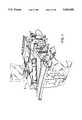
- FIG. 1is a top perspective view of the prone patient supporting mammography table of the present invention
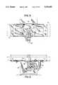
- FIG. 2is an end perspective view of the same table showing the base, pedestal and angularly movable C-arm carrying the X-ray tube and the image receptor, as well as the separate compression arm carrying compression plates and needle guide;
- FIG. 3is a front elevation view of the same table supporting a prone female patient at maximum elevation above the floor, delivering X-radiation to the underside of the breast, toward the table's right end;
- FIG. 4is a schematic top plan view of the table showing the range of X-ray tube positions made possible by the rear pedestal construction of the unit;
- FIG. 5is a top plan view of the table of FIGS. 1-3, with the C-arm positioned for delivering X-radiation from the side of the patient;
- FIG. 6is a schematic front elevation view of the same table, with the C-arm positioned for delivering X-radiation toward the table's left end;
- FIGS. 7A, 7B and 7Care corresponding successive fragmentary top plan schematic views showing the compression arm carrying the breast compression plates and needle guide in a fixed position beneath the table, while the underlying C-arm carrying the X-ray tube and image receptor is moved to different angular positions;
- FIG. 8is a schematic diagram of the stereotactic mammography procedure of this invention, comparing the X-radiation paths through a suspect lesion and a reference point on the compression plate for two angularly offset tubehead source positions, when the image receptor pivots with the tubehead on the C-am;
- FIG. 9is a fragmentary enlarged schematic diagram showing the lower end of FIG. 8 in more detail.
- FIG. 10is a schematic diagram of the two images produced at the image receptor by X-radiation from the same two source positions;
- FIGS. 11 and 12are schematic diagrams of the X-radiation paths for two angularly offset stereo tubehead source positions utilizing a folded CCD optical imaging system inserted in the position occupied by the X-ray film cassette in film mammography but with the digital CCD optical imaging system of FIGS. 13-17 pivoting with the tubehead.
- FIG. 13is a top plan schematic view of the conventional stereotactic mammography procedure performed on prior art devices, showing the X-radiation arriving at significant angles of inclination from the perpendicular, introducing undesired image degradation, when the image receptor is stationary.
- FIG. 14is a schematic diagram illustrating the stereotactic images employed to identify the coordinates of the target lesion with the imaging system of FIG. 13;
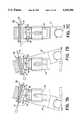
- FIG. 15is a perspective top view of the folded optical system employed in the stereotactic CCD imaging system of FIGS. 11 and 12, with a portion of the light-tight housing removed to reveal the location of the various components of the optical system;
- FIG. 16is a top plan view of the thin film pellicle mirror employed in the optical system of FIG. 15;
- FIG. 17is an edge elevation view of the same pellicle mirror
- FIG. 18is a schematic diagram showing the imaging of the patient's compressed breast on a phosphor plate in the optical system delivering a focussed image to the CCD sensor and the processing of the CCD output signals through the image enhancement computer to the monitor screen display.
- FIG. 19is a detailed schematic diagram of a preferred form of CCD camera employed in the optical system of FIG. 15.
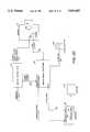
- FIG. 20is an overall block diagram of the system electronics used to convert the digital information from the CCD camera into mammographic display information as presented on the monitor driven by an associated computer.
- FIG. 21is a detail block diagram of the digital control logic module shown in FIG. 20.
- FIG. 22is a detail block diagram of the analog signal processor module shown in FIG. 20.
- FIG. 23is an overall diagrammatic view of the CCD camera and its associated electronics
- FIG. 24is a diagram illustrating the number of pixels of an overall typical image which have particular luminance values.
- FIGS. 1-7CThree principal components or sub-assemblies are incorporated in the preferred embodiments of the present invention. These are the adjustable and versatile prone patient supporting table shown in FIGS. 1-7C, the novel CCD imaging folded optical system shown in FIGS. 11, 12 and 15-17, and the image enhancement and data display monitor systems providing high resolution and nearly real time image displays in the systems of the invention as illustrated schematically in FIG. 18.
- Patient supporting table 21comprises platform 22 on which the patient rests in a prone position, supported by a rear pedestal 23 upstanding from the rear portion of a base 24, all as shown in FIG. 1.
- Pedestal 23preferably incorporates table elevating means to raise and lower the table within limits for convenience of the patient and attending personnel.
- a ledge 26Protruding forward over the lower part of base 24 from the front face of pedestal 23 is a ledge 26 sturdily constructed to provide underlying support for an angularly movable "C-arm" 27.
- Arm 27is shaped like a letter C lying on its back, with one upstanding end mounting the X-ray source or mammography unit tube head 28.
- the pivot axis 29, about which C-arm 27 is mounted for angular rotation relative to ledge 26,is close to the opposite upstanding end of the C-arm 27, and this upstanding end incorporates either X-ray film cassette 31 or CCD sensor folded optical system 32 enclosed in a light-tight housing and shown schematically in FIGS. 11 and 12, and in the perspective top view of FIG. 15.
- the upper portion 33 of pedestal 23 supporting the table platform 22 at its upper end and the ledge 26 at its lower endis capable of vertical downward movement from the raised position shown in FIG. 3 to a lowered position in which the ledge 26 is close to base 24, shown in FIG. 1.
- This vertical adjustment motionis provided by telescoping upper pedestal portion 33 over the underlying lower pedestal portion 34 shown in FIG. 3.
- the uppermost position 28A of tubehead 28places it within the underside recess 49 formed in table platform 22 (FIG. 3) with the opposite end of the C-arm 27 comprising the image receptor 36, carrying either the X-ray film cassette 31 or the optical system 32, preferably being closely positioned adjacent the underside of table 22 as shown in FIG. 3, in order to bring the X-ray beam and the image receptor as close as possible to the chest wall of the patient lying prone, face down on platform 22.
- a central aperture 37is provided in the central portion of platform 22 accommodating one or both of the female patient's breasts depending therethrough as the patient lies face down on platform 22. Since image receptor 36 is relatively thin, as shown in FIGS. 3 and 5, and is positioned close to the pivot axis 29 about which the C-arm moves angularly, the pivoting movement of C-arm 27 about axis 29 allows the image receptor 36 to be positioned between the patient's breasts, or against the underside of either breast, by making minor adjustments in the position of axis 29 relative to ledge 26.
- a fixed compression plate 53 and a compression paddle 38 movable toward and away from plate 53are mounted above the C-arm 27 on an independently pivoted compression arm 50.
- Compression paddle 38may be considered a biopsy compression device, since it incorporates both a transparent portion permitting X-rays to pass through it toward the patient's breast and image receptor 36, and a central needle access aperture.
- the compression arm 50also incorporates mechanism for attaching a needle guide 39 for performing a needle biopsy without releasing the breast from the compression plate, thereby assuring that the target lesion coordinates determined by the original stereotactic measurements will be maintained upon insertion of the needle to reach the same target lesion coordinates.
- table 22 shown in FIGS. 1 through 6incorporates an additional useful feature, a central concave torso depression 35 surrounding the central aperture 37.
- Depression 35provides comfortable support for the prone patient's head, shoulders and torso, with her hips and legs extending either to the right or to the left over the slightly higher end portions of table 22, which may also incorporate the footrests 43 and 44 if desired.
- the central position of aperture 37, and the footrests 43 and 44 at both ends of the support tables 22 or 22A,provide double the 210° range of available X-ray projection angles indicated in FIG. 4, a range of some 420°.
- No conventional mammography tablesare known to afford such a wide range of projection angles.
- the slight elevation of the patient's hips by depression 35maintains the normal relaxed curve of the patient's vertebra, while presenting the maximum possible volume of breast tissue through aperture 37 for X-ray examination.
- the slight elevation of the ends of table 22 outside of the central depression 35provides the underside recess 49 encircling aperture 37, with vertical clearance for the upper end of X-ray tubehead 28 under table 22. This permits the focal point source FP of X-radiation to be elevated to a level nearly in tangent coincidence with the lower rim of aperture 37, providing desirable exposure of the maximum volume of the patient's pendulant breast tissue for examination.
- the front edge of platform 22 beside aperture 37, opposite pedestal 23,is preferably formed as a removable panel 41, providing unimpeded access beneath platform 22 for the radiologist and technicians, and permitting the patient's arm to be lowered through the open space left by the removal of the panel 41 (FIG. 4) bringing her shoulder comfortably down toward the level of aperture 37 (FIG. 3) and minimizing any distortion or stretching of the breast pendulant through aperture 37.
- FIGS. 3-6Different positions of tubehead 28 produced by angular movement of C-arm 27 are illustrated in FIGS. 3-6, along the circular arcuate path 42 shown in FIG. 4.
- X-radiation projected toward axis 29will approach a lesion from the lateral aspect of the right breast or the medial aspect of the left breast if the patient's head is positioned to the right on platform 22, as in FIG. 3.
- the footrest 43 at the left end of platform 22is preferably extended to support the patient's legs in this position, while the footrest 44 at the right end of platform 22 is preferably retracted toward the table end to the dash line position 44A shown in FIG. 4.
- X-radiation from tubehead position 28Bapproaches the lateral aspect of the left breast or the medial aspect of the right breast.
- the X-radiationapproaches the breast from either above or below, with the image receptor 36 being positioned on the opposite side of the breast and the compression plate 53 and paddle 38 assuring that the patient is comfortably positioned with no risk of unexpected movement during the procedure.
- the tubehead 28 delivering X-rays to the patientwill be positioned at the patient's head end of platform 22 with image receptor 36 and compression plate 53 being positioned on the underside of the pendulant breast and the compression paddle 38 being positioned on the upper side of the breast, both mounted on compression arm 50, which also provides support for needle guide 39 from this upperside when required.
- image receptor 36 and compression plate 53being positioned on the underside of the pendulant breast
- the compression paddle 38being positioned on the upper side of the breast, both mounted on compression arm 50, which also provides support for needle guide 39 from this upperside when required.
- the presence of a lesion near the underside of the breastmay indicate that the reverse orientation is preferred for minimum trauma, as indicated in FIG. 3, with the needle guide 39 and compression paddle 38 being positioned on the underside of the breast with the X-ray tubehead 28 being positioned beyond compression plate 53 on the upper side of the breast.
- the entry of the biopsy needle via needle guide 39 attached to compression paddle 38 into the underside of the breast tissueoffers the minimum path length for access to the lesion, and this position may be preferred by many patients to assure that any needle scar will be on the underside of the breast where it is less easily observed.
- Two additional tubehead positions 28E and 28Fare also shown in FIG. 4, these being respectively displaced angularly by approximately 15 degrees counterclockwise and 15 degrees clockwise, which are typical angular displacements for stereotactic mammography.
- lesser angular amountsof 10 degrees for example, on each side of the longitudinal axis 46 of platform 22 can be used if desired, to assure that the stereoscopically displaced images both fall on the desired portion of the image receptor, whether it be X-ray film in a film cassette 31 or the electronic imaging optical system 32 illustrated in the figures.
- Stereoscopic displacement of the lesion imagemay place it near the periphery of the total image plane in particular lesion orientations, and for this reason, a lesser stereo displacement of the positions 28E and 28F may be indicated.
- the cassette 31When the film cassette 31 is utilized at the image receptor 36 in stereotactic mammography, the cassette 31 may be provided with a film position shift lever 47, shown in FIGS. 7A-7C, and movement of this lever shifts the film cassette position so that stereo exposures at plus 15 degrees and minus 15 degrees angular displacement from axis 46 will be exposed side by side on the X-ray film. While the patient remains on platform 22 and the compression paddle 38 remains in position, the cassette may be removed and the film developed and examined to provide actual coordinates of the target lesion for needle biopsy.
- a film position shift lever 47shown in FIGS. 7A-7C
- a new film cassette 31may be placed in position on receptor 36 and two more stereo mammograms may be made to assure that the tip of the needle is at the desired location in the target lesion. Removal and development of this second cassette verifying the needle tip location thus permits any final adjustments required, and the needle biopsy may then be completed immediately.
- X-, Y- and Z- axis indexing of needle guide 39 relative to the patient's breast tissueis provided by linear motorized adjustments mounted on an indexing carriage 45 movably mounted on linear bearings on the compression arm 50 pivoted on ledge 26 above pivoting tubehead C-arm 27.
- An indexing knob 48 cooperating with a timing belt or endless chain drivemoves carriage 45 and compression paddle 38 into gentle compressive contact with the patient's breast 52, clamping it gently but firmly against the fixed breast compression plate 53.
- X, Y or Z control knobs on carriage 45permit the operator to position the needle guide 39, adjusted for biopsy as required by the lesion coordinates found by stereotactic X-ray observations.
- the X-axisis horizontal, extending toward pedestal 23; the Y-axis is vertical, extending upward toward the patient, and the Z-axis extends horizontally, parallel to table platform 22, toward X-ray tubehead source 28.
- the "pivot point" where pivot axis 29 intersects the X-Z plane passing through source focal point FP,is taken as the origin or zero-point for X, Y and Z values.
- the electronically enhanced CCD sensor optical system 32When the electronically enhanced CCD sensor optical system 32 is employed in place of the film cassette 31, a much shorter time is required for completion of the entire procedure.
- the stereotactic procedure just described with two X-ray film cassettescustomarily takes between 20 and 70 minutes during which time the patient must remain in the same position face down on the mammography table.
- the digital image data received and processed in the system shown schematically in FIG. 18ideally permits the mammography, the needle placement, the X-ray verification of needle location and the needle biopsy all to be completed within a period of one to two minutes, and certainly within a period far less than the 20 to 70 minutes normally experienced with customary X-ray film cassettes in stereotactic mammography.
- table 22projects forward and is supported cantilever-fashion along its rear edge by rear pedestal 23.
- the wide clear open space under table 22provides ample room for X-ray tubehead 28 to move pivotally through the infinite range of positions including those shown in the FIGURES: left longitudinal positions 28A or 28D (FIGS. 3, 4); stereo-offset positions 28E or 28F (FIG. 4); lateral position 28B (FIGS. 4, 5) and right longitudinal position 28C (FIGS. 4, 6).
- FIG. 13shows a schematic diagram of such prior art two-source-position stereotactic X-ray mammography with a lesion 51 in the tissue of a patient's breast 52 compressed between a fixed compression plate 53 and an adjustable compression paddle 38, both of which are transparent to X-rays.
- the fixed compression plate 53preferably coincides with the position of image receptor 36 shown in FIG. 13 and comprises the proximal surface of receptor 36.
- receptor 36 of the present inventionWhen image receptor 36 of the present invention is mounted on the C-arm 27 for pivoting movement with the X-ray tubehead 28 source FP, as shown in FIGS. 2, 3 and 6-12, receptor 36 is spaced far enough behind pivot axis 29 to afford clearance for the desired angular pivoting motion.
- An additional advantage of the mounting of the image receptor on the C-armarises from the usefulness of bucky grids with divergingly slanted vanes to pass direct X-radiation from the source FP while blocking laterally scattered or secondary X-radiation which would otherwise reduce image sharpness.
- the bucky gridis mounted on the image receptor 36 pivoting with the tubehead C-arm 27, its diverging vanes are aligned with source FP in all of its adjusted stereo positions shown in FIGS. 7A and 7B.
- a stationary bucky mounted in front of the image plane in the prior art image receptor of FIG. 13can have its vanes aligned with only one X-ray source point, interfering with some of the desired direct X-radiation projected from other, offset source points and seriously reducing the bucky's usefulness.
- the determination of X-, Y- and Z- coordinates of suspect lesionsis performed by calculating the equations of slope for the X-ray paths passing through the lesion and through a reference point 40 on the compression 38 to a first image plane for the first source position S1 or 28E (FIGS. 4, 8) and for the second source position S2 or 28F.
- the coordinates of the suspect lesion 51are X, Y and Z.
- Points 1 and 2are the Y and X positions of the reference hole 40 image on the left image area in FIG. 10, produced when the source is at S2 or 28F.
- Points 3 and 4are the X and Y positions of the hole 40 image on the right image area, produced when the source is at S1 or 28E.
- Points 5 and 6are the images of the suspect lesion 51 in the two image areas of FIG. 10.
- This methodis based on finding the equations of the two source-to-image lines for the two lesion images. The intersection of the two lines provides the X, Y and Z coordinates, on the X-Y, Y-Z and X-Z planes.
- FIG. 8shows the X-Z plane as viewed from below.
- the pivot point, where the pivot axis 29 passes through the X-Z plane,serves as the zero point for both X and Z values, for analytical purposes.
- FIG. 9is an enlarged view of the portion of the same diagram around the pivot point.
- Mdistance from projected pivot point to compression reference hole 40 images E, F (see FIGS. 8, 9 and 10).
- FIGS. 11 and 12The principal internal components of the folded optical system 32 are shown schematically in FIGS. 11 and 12, and in the cutaway top perspective view of FIG. 15, where the X-ray transparent cover plate 60 forming the proximal or front wall of housing 54 has been removed from its supporting proximal flanges 56, to reveal the internal structures inside housing 54.
- an upper housing panel 57has been removed from its upper supporting flanges 58, thus revealing the internal structure of the optical system 32. Fragmentary broken away portions of panel 57 and cover plate 60 are shown at the left side of FIG. 15.
- radiation from the X-ray tubehead 28passes successively through the X-ray transparent adjustable compression paddle 38, the patient's breast 52, the fixed compression plate 53, and then through a thin film pellicle mirror 59.
- Thisis a film of high tensile strength elastic membrane material such as nitrocellulose having a thickness ranging between 5 and 9 microns (micrometers), for example, stretched like a drumhead over a flat metal frame 61 (FIG. 15) and bonded to the precision lapped edge of this frame.
- the thin pellicle filmis virtually transparent to X-radiation which passes directly through it to impinge upon the underlying phosphor screen 62 mounted on the image plane at the rear wall 63 of the housing 54.
- X-ray opaque index marksPositioned at points B1 and B2 on the X-ray transparent fixed compression plate 53, in the prior art fixed image receptor of FIG. 13, are X-ray opaque index marks which may take the form of cross hairs as indicated in FIG. 14. These index marks are imaged as shown by the crosses B1 and B2 in FIG. 14, which comprises a vertical projection of the various points along the path of the X-rays proceeding through the system shown schematically in FIG. 13.
- the point S1 in FIG. 14corresponds to the vertical projection on the image plane of the source position 28E at which the tubehead 28 is first angularly offset, as indicated in FIGS. 4 and 13.
- point S2 on the image planeis the vertical projection of the second tubehead source position 28F shown in FIGS. 4 and 13.
- index point B2is determined by the crossing of the vertical projections of the X-ray paths S2P1 and S1P3.
- the X-ray path from source S1 through lesion 51creates the vertical projection X-ray path S1L1 on the image plane and the crossing of this projected line with line S2L2 indicates the position at which the lesion appears in the stereo projection of FIG. 14.
- this datamay be recorded digitally and manipulated to provide highly accurate X, Y and Z coordinates for the actual position of the lesion.
- This digital data handling operationis facilitated by the optical system 32, shown in FIGS. 11, 12 and 15-18.
- Theseinclude the coated underside of the pellicle mirror 59 which serves as a mirror reflecting the image of the image plane phosphor plate 62 toward a second mirror 64, which delivers the reflected image of the phosphor plate 62 to lens 66 of the CCD equipped camera 67.
- the image of the phosphor screen 62is reflected from the underside of pellicle film 59 to the right toward the angularly positioned mirror 64 which then directs it downward toward the lens 66, clearly shown in FIG. 15 overlying the CCD camera 67.
- the pellicle film's reflective undersurfacereflects the visible light image toward the CCD camera, avoiding any diffusion or losses from transmission through the phosphor plate 62.
- the diagonal positioning of film 59necessarily requires spacing plate 62 away from X-ray transparent cover plate 60. Phosphor plate 62 thus receives the direct X-rays passing from the tubehead through the target, but most secondary or scattered X-rays produced within the target are lost, leaving a clean, sharp resulting image on plate 62.
- the cameraoperating in the snapshot mode, integrates the image from the phosphor plate 62 and at the end of the exposure, the image is stored in computer memory. This operation is performed for the image produced by X-ray source position 1 at tubehead position 28E, and it is then repeated for source position 2 at tubehead position 28F and another exposure is made. Thus in a few seconds, two stereo pair images are obtained and stored in the computer. The operator then brings the images to the monitor and using a track ball, places cursor locators on the calibration marks B1 and B2 and on the lesion.
- the computerBased on the position of these cursors on the monitor screen, the computer then calculates the X, Y and Z location of the lesion relative to the breast compression paddle 38 and plate 53.
- These X, Y and Z coordinatesmay be used immediately for fine needle or core biopsy, using the needle guide to direct the biopsy needle to the site of the lesion, where two more stereo images are recorded to confirm the accurate positioning of the needle tip at the lesion site. Alternatively, these images may also be employed to guide surgery if desired.
- the pellicle film thicknesspreferably falls between five and nine micrometers, and most desirably falls within the range of six to seven micrometers, with the thickness uniformity being accurate and the faces of the film being parallel within two wavelengths of X-radiation per inch.
- a coating of aluminum and silicon dioxide on the underside of the pellicle filmprovides a reflectance greater than 8%, with no pinholes being visible to the unaided eye, thus assuring the uniformity of the resulting CCD image.
- the unique "D-shaped" configuration of the pellicle mirror 59 and frame 61 in the optical systems of the preferred embodiments of the inventionprovide a unique advantage: the rectangular area 68 corresponding to the pellicle film reflection of the phosphor plate 62 is uniformly smooth and flat over its entire surface and it will be noted that the circular sector of frame 61 subtends approximately 250 degrees, while the straight chord 69 closing the D-shaped frame 61 subtends the remaining angle of about 110 degrees. This D-shaped frame 61 thus brings the critical-area 68 very close to the adjacent chord segment 69 of frame 61, as shown in FIG. 16.
- Chord segment 69is positioned closely adjacent to upper housing panel 57, as can be observed in FIG. 15, thus bringing the critical area for imaging X-radiation passing through the patient's breast 52 close to table platform 22, and producing a visible image on the phosphor plate 62 in close juxtaposition with upper housing panel 57, which is positioned vertically as close as possible to the patient's chest wall.
- the maximum volume of the patient's breast 52is exposed to the mammographic examination using the X-radiation passing through the D-shaped pellicle mirror 59.
- FIGS. 7A-7C, 11 and 12show the preferred embodiment of the invention in which the light-tight housing 54 is independent of fixed compression plate 53 and is mounted for pivoting movement on the C-arm with tubehead 28 about a pivot axis 29 spaced slightly away from fixed compression plate 53. Tubehead 28 and housing 54 thus pivot together as a unit, from position 28E-54E in FIG. 18 to position 28F-54F in FIG. 19. A substantial portion of the patient's breast 52 can then be viewed in each position, in a wide image utilizing virtually the full width of phosphor plate 62, as shown in these figures.
- FIGS. 11 and 12show a second feature characterizing this embodiment: the X-ray opaque index marks B1 and B2, like reference hole 40, are positioned on movable compression paddle 38, rather than on fixed compression plate 53, to assure that-diverging radiation paths from either source position passing through the index marks will fall within the useful image area of phosphor plate 62.
- CCD Camera 67is shown schematically in more detail in FIG. 19.
- lens 66is supported on a lens mount 71 positioned on the front face 73 of camera body 72.
- Face 73incorporates a light-transparent window 74 behind which CCD array 76 is positioned.
- Light focused by lens 66is delivered through window 74 to a focal plane corresponding to the face of CCD array 76.
- Array 76is mounted on the front end of a "cold finger" pedestal 77 whose rear end is anchored to a Peltier thermoelectric cooler 78 mounted on the camera body's rear face 79 with heat-transfer fins 81 extending into the ambient atmosphere.
- a ring-shaped printed circuit board 80closely encircles "cold finger” pedestal 77, minimizing resistance losses in the conductors (not shown in FIG. 19), connecting CCD array 76 to board 80.
- CCD array 76positioned at the focal plane of lens 66, receives a focused image of the light produced by phosphor plate 62 via mirrors 59 and 64, and the array is quickly scanned, facilitating the storing of the image in memory for manipulation, enhancement and future study as desired, without any delays such as those required for processing of X-ray film.
- the computer and associated system electronics forming part of the overall digital mammography systemcomprises computer 100, a control module 102, a module 104 for presentation of mammography information, disc drive 106 and keyboard 108 associated with computer 100.
- the system electronicsinclude an interface card 110 and a video display card 112 which reside within computer 100.
- a digital control logic module 114 and an analog signal processor 116form the overall control module 102.
- the digital control logic modulegenerates various clocking signals for transfer to the camera 67 for use by CCDs 76.
- the output of the CCDsare applied through a preamplifier 120 so as to generate a CCD output signal on a bus 122 for presentation to the analog signal processor 116.
- FIG. 21is a detailed block diagram of the digital control logic module 114 and illustrates the specific clock signals generated on output bus 124 as well as the clamped sample and data transferred between this module and the analog signal processor module 116 on output bus 126.
- An integrate control signal from the computeris also shown received on line 130 to the main control logic module 132.
- analog signal processor module 116Details of the analog signal processor module 116 are shown in the detail block diagram of FIG. 22. As seen in FIGS. 20 and 22 an X-ray status signal indicating the presence of X-rays from X-ray detector 134 is presented on input status line 136.
- the CCD output signal received on line 122is presented to an input amplifier 138 and from there presented under control of the clamp and sample signals to two sample and hold modules 140 and from there to differential amplifier 142 and buffer 144 so as to be presented to a 12 bit analog digital converter 146 so as to present the digital output of the CCD image to a first in first out (FIFO) memory 148.
- the output of the FIFO memoryis connected to the computer interface card 110 for display and image processing by the computer so as to present via display card 112 an output image onto monitor 104. (See FIGS. 18-20).
- FIG. 23is a detailed diagrammatic view of the camera 67 and its associated electronics illustrating the serial clock inputs from the digital control logic module 114 via bus 124; the output of CCD digital data via bus 122; the input of V clocks (parallel clock) information on bus 24; as well as bias voltages from the analog and digital control logic modules 114 and 116.
- the overall imaging system shown in FIG. 20provides an image of the mammographic information on display monitor 104.
- the digitized CCD data received on bus 150 from FIFO memory 148(see FIG. 22) is under the control of computer 100 via execution of a computer program as set forth in a program listing Table 2.
- Table 2the program for achieving mammographic display as well as digital image processing of the mammographic information is written in Microsoft Corporation assembly language as well as Microsoft "C" high level language.
- the image presented on monitor 104comprises 512 ⁇ 512 pixels of mammographic information on a video display of 1024 ⁇ 768 pixels, with each pixel having a luminance resolution of 8 bits or 256 luminance values.
- the present inventioncan also support a pixel size display up to 1,024 ⁇ 1,024 pixels.
- the value of the luminance from the CCD camerahas a resolution of 12 bits or 4,096 luminance values.
- the 12-bit luminance information from the CCD cameracould be displayed with use of a video display card and monitor having such higher luminance imaging capability.
- the CCD cameracan output data in a 512 ⁇ 512 pixel array or in a 1024 ⁇ 1024 pixel array. If the higher resolution array is used, monitor 104 displays a 1024 ⁇ 768 portion of the CCD data with 128 rows at the top and bottom of the CCD image typically masked; although the viewed image can be scrolled throughout the CCD image.
- the computer program listing set forth in table 1basically performs the following steps in its display of mammographic information: (1) generates 12 bit luminance information for each pixel in the overall display area via subtracting a dark field and removing fixed pattern noise associated with the particular CCD imaging device, (2) divides the dark field by a white field sometimes referred to as "flat fielding" so as to even out any unevenness in the luminance X-ray information as a result of non-uniform X-ray beam illumination, and (3) produces a luminance histogram of the displayed data.
- the digital image processing of the present inventionallows for increasing the contrast which effectively narrows the luminance window as well as providing movement of the luminance window with regard to the luminance range of values for which proportional gray-scaling is implemented; that is to move the window with respect to the CCD luminance values of 0 to 4,095.
- This functionis sometimes referred to as "windowing".
- the contrast displayed on monitor 104can be increased by reducing the luminance values that are displayed. For example, the luminance values from 1,000 to 1,511 could be displayed out of all luminance values from 0 to 4,095.
- the luminance values from the CCD cameracould be inversely displayed on the monitor. For the example above, all luminance values equal to or less than 1,000 could be displayed as black, and vice versa for luminance values equal to or greater than 1511. It should also be noted that rapidly inverting the displayed data can help the operator to see features of the image than otherwise possible if only one video polarity is displayable.
- Windowingis the ability to slide the range of values to be displayed up or down the luminance 4,096 values from the CCD camera.
- the 512 different luminance values displayable on monitor 104could be slid down so as, for example, to include pixel luminance values from 70 to 581, or slid upward, to include pixel luminance values from 4,020 to 4,531, for example.
- This combination of constant control and windowingprovide significant diagnostic imaging improvement for the original CCD imaging data received from the camera.
- a luminance histogramcan be produced by the imaging system.
- This luminance histogramis then used in a process sometimes referred to as auto-gray scaling.
- this processanalyzes the CCD imaging data to determine what luminance values are predominantly obtained for a particular image. For example, an image might have most pixels at luminance values in a range of 2,000 to 3,000. Typically, the number of pixels at particular luminance values would have a characteristic bell-shape curve such as shown in FIG. 24.
- the systemdetermines that the majority of pixel luminance values predominantly lie between 2,000 and 3,000 and thus would display only those values as gray scale on the monitor. Those pixels with luminance values equal to or less than 2,000 would be displayed as white while pixel values equal to or greater than 3,000 would be displayed as black.
- the processis therefore similar to selecting the luminance values to be displayed for contrast enhancement.
- the present inventionalso incorporates convolution filtering and edge enhancement which can operate on all or a subset of the displayed image.
- convolution filteringa kernel having a matrix size of 3 ⁇ 3 pixels or 5 ⁇ 5 pixels can be used around each pixel for which such convolution filtering is desired.
- the implementationuses a lookup table technique for the gray scale associated with the screen luminance and thus provides a luminance to gray scale image mapping as described above.
- Additional featuresalso include a high pass filtering so as to sharpen details as well as low pass filtering so as to remove high spatial noise which effectively provides for edge enhancement for rapidly changing data.
- the present inventioncan perform "histogram equalization” and "contrast stretching". Similar to the convolution filtering described above, these functions can operate on all or a subset of the displayed image, sometimes referred to as the region of interest. "Contrast stretching” effectively stretches the gray-scale over the region of interest, thereby using the entire available range of displayable grayscale only in this region of interest.
- histogram equalizationthe system remaps the data in the region of interest so that the resulting data has an equal number of occurrences for each histogram bin. In other words, if one looked at the luminance histogram in the region of interest after doing histogram equalization, each bar of the histogram would have the same height rather than the bell shape curve as shown in FIG. 24. Histogram equalization helps to enhance the grayscale rendition for certain image making visualization of abnormalities easier.
- the stereotactic imaging explained aboveuses cursor marking of the displayed image and is implemented in the program listings forming Table 2.
- Positioned information in digital forminterfaces with the X, Y or Z control knobs on the needleguide stage or carriage 45 (FIGS. 6, 7) actuated manually or servodriven, and a null indication signals matching of calculated with actual coordinates.
- This interfacingcorresponds to the manual calculation of coordinates using a "digitizing pad" with a film grid system like those used with computer pads, to produce the same matching with the actual coordinates of the needle guide stage.
- the overall operation of the various program modulesare explained via the comments associated with those modules in program listing Table 2.
- the overall resultis not only to present the digitized information but to provide for overall enhancement of the information including zooming of specific regions of interest, edge enhancement, contrast enhancement as well as artifact removal associated with the CCD imaging sensors.
- the digital image processingprovides much greater information to the examining physician than that available using radiographic imaging.
Landscapes
- Health & Medical Sciences (AREA)
- Life Sciences & Earth Sciences (AREA)
- Engineering & Computer Science (AREA)
- Medical Informatics (AREA)
- Surgery (AREA)
- Public Health (AREA)
- Molecular Biology (AREA)
- General Health & Medical Sciences (AREA)
- Nuclear Medicine, Radiotherapy & Molecular Imaging (AREA)
- Animal Behavior & Ethology (AREA)
- Pathology (AREA)
- Veterinary Medicine (AREA)
- Biomedical Technology (AREA)
- Heart & Thoracic Surgery (AREA)
- Oral & Maxillofacial Surgery (AREA)
- Biophysics (AREA)
- Radiology & Medical Imaging (AREA)
- Optics & Photonics (AREA)
- High Energy & Nuclear Physics (AREA)
- Physics & Mathematics (AREA)
- Dentistry (AREA)
- Neurosurgery (AREA)
- Apparatus For Radiation Diagnosis (AREA)
- Image Processing (AREA)
Abstract
Description
TABLE 1 ______________________________________Computer 100 IBM compatible personal computer with an Intel type 80386 ™ or 80486 ™ processor and 12 to 16 Mb RAM, and 200 MB hard disk storageVideo display card 112 Trident Impact 3 ™ video display card with 1024 × 768 pixel resolution and 8 bit luminance resolution perpixel Monitor 104 Dotronix M2400 ™ 20 inch monochrome monitor with P104 phosphor, set to vertical and horizontal scan rate of video card; analog input. ______________________________________
Claims (6)
Priority Applications (3)
| Application Number | Priority Date | Filing Date | Title |
|---|---|---|---|
| US08/185,690US5426685A (en) | 1991-11-27 | 1994-01-24 | Stereotactic mammography system imaging |
| US08/388,810US5609152A (en) | 1991-11-27 | 1995-02-15 | Prone position stereotactic mammography needle biopsy apparatus and method for using the same |
| US08/437,793US5594769A (en) | 1991-11-27 | 1995-05-09 | Method and apparatus for obtaining stereotactic mammographic guided needle breast biopsies |
Applications Claiming Priority (3)
| Application Number | Priority Date | Filing Date | Title |
|---|---|---|---|
| US79941291A | 1991-11-27 | 1991-11-27 | |
| US07/957,275US5289520A (en) | 1991-11-27 | 1992-10-06 | Stereotactic mammography imaging system with prone position examination table and CCD camera |
| US08/185,690US5426685A (en) | 1991-11-27 | 1994-01-24 | Stereotactic mammography system imaging |
Related Parent Applications (1)
| Application Number | Title | Priority Date | Filing Date |
|---|---|---|---|
| US07/957,275DivisionUS5289520A (en) | 1991-11-27 | 1992-10-06 | Stereotactic mammography imaging system with prone position examination table and CCD camera |
Related Child Applications (1)
| Application Number | Title | Priority Date | Filing Date |
|---|---|---|---|
| US08/388,810DivisionUS5609152A (en) | 1991-11-27 | 1995-02-15 | Prone position stereotactic mammography needle biopsy apparatus and method for using the same |
Publications (1)
| Publication Number | Publication Date |
|---|---|
| US5426685Atrue US5426685A (en) | 1995-06-20 |
Family
ID=27122112
Family Applications (3)
| Application Number | Title | Priority Date | Filing Date |
|---|---|---|---|
| US07/957,275Expired - LifetimeUS5289520A (en) | 1991-11-27 | 1992-10-06 | Stereotactic mammography imaging system with prone position examination table and CCD camera |
| US08/185,690Expired - LifetimeUS5426685A (en) | 1991-11-27 | 1994-01-24 | Stereotactic mammography system imaging |
| US08/388,810Expired - LifetimeUS5609152A (en) | 1991-11-27 | 1995-02-15 | Prone position stereotactic mammography needle biopsy apparatus and method for using the same |
Family Applications Before (1)
| Application Number | Title | Priority Date | Filing Date |
|---|---|---|---|
| US07/957,275Expired - LifetimeUS5289520A (en) | 1991-11-27 | 1992-10-06 | Stereotactic mammography imaging system with prone position examination table and CCD camera |
Family Applications After (1)
| Application Number | Title | Priority Date | Filing Date |
|---|---|---|---|
| US08/388,810Expired - LifetimeUS5609152A (en) | 1991-11-27 | 1995-02-15 | Prone position stereotactic mammography needle biopsy apparatus and method for using the same |
Country Status (9)
| Country | Link |
|---|---|
| US (3) | US5289520A (en) |
| EP (2) | EP0644740B1 (en) |
| JP (1) | JP2691073B2 (en) |
| KR (3) | KR0138835B1 (en) |
| CA (1) | CA2122255C (en) |
| DE (1) | DE4294430T1 (en) |
| GB (4) | GB2297231B (en) |
| SE (1) | SE511432C2 (en) |
| WO (1) | WO1993011706A1 (en) |
Cited By (105)
| Publication number | Priority date | Publication date | Assignee | Title |
|---|---|---|---|---|
| US5579360A (en)* | 1994-12-30 | 1996-11-26 | Philips Electronics North America Corporation | Mass detection by computer using digital mammograms of the same breast taken from different viewing directions |
| US5692511A (en)* | 1995-06-07 | 1997-12-02 | Grable; Richard J. | Diagnostic tomographic laser imaging apparatus |
| WO1998002095A1 (en)* | 1996-07-12 | 1998-01-22 | United States Surgical Corporation | Sonography and biopsy apparatus and methods of use |
| US5776062A (en)* | 1996-10-15 | 1998-07-07 | Fischer Imaging Corporation | Enhanced breast imaging/biopsy system employing targeted ultrasound |
| US5825910A (en)* | 1993-12-30 | 1998-10-20 | Philips Electronics North America Corp. | Automatic segmentation and skinline detection in digital mammograms |
| US5833627A (en) | 1995-04-13 | 1998-11-10 | United States Surgical Corporation | Image-guided biopsy apparatus and methods of use |
| US5848123A (en)* | 1995-11-21 | 1998-12-08 | Planmed Oy | Methods and apparatus for use in imaging an object |
| US5851180A (en)* | 1996-07-12 | 1998-12-22 | United States Surgical Corporation | Traction-inducing compression assembly for enhanced tissue imaging |
| US5894844A (en)* | 1996-11-07 | 1999-04-20 | Rohrberg; Roderick G. | Three-dimensional floatation-enhanced body examination system |
| US5938613A (en) | 1993-10-29 | 1999-08-17 | United States Surgical Corporation | Methods and apparatus for performing sonomammography and enhanced X-ray imaging |
| US5970164A (en)* | 1994-08-11 | 1999-10-19 | Sophisview Technologies, Ltd. | System and method for diagnosis of living tissue diseases |
| US5983123A (en) | 1993-10-29 | 1999-11-09 | United States Surgical Corporation | Methods and apparatus for performing ultrasound and enhanced X-ray imaging |
| US6027457A (en) | 1998-06-18 | 2000-02-22 | United States Surgical Corporation | Apparatus and method for securing tissue during ultrasound examination and biopsy |
| US6029077A (en)* | 1996-11-08 | 2000-02-22 | Imaging Diagnostic Systems, Inc. | Device for determining the perimeter of the surface of an object being scanned and for limiting reflection from the object surface |
| WO2000015112A1 (en)* | 1998-09-17 | 2000-03-23 | Quanta Vision, Inc. | Reduced-angle mammography device and variants |
| US6044288A (en)* | 1996-11-08 | 2000-03-28 | Imaging Diagnostics Systems, Inc. | Apparatus and method for determining the perimeter of the surface of an object being scanned |
| US6050954A (en)* | 1998-08-21 | 2000-04-18 | Manan Medical Products, Inc. | Biopsy needle orientation fixture |
| US6195580B1 (en) | 1995-07-10 | 2001-02-27 | Richard J. Grable | Diagnostic tomographic laser imaging apparatus |
| US6261299B1 (en)* | 1999-11-26 | 2001-07-17 | The Ohio State University | Stereotactic apparatus and methods |
| RU2171628C2 (en)* | 1998-09-17 | 2001-08-10 | Кванта Вижн, Инк. | Device for small-angle mammography (modifications) |
| US6463122B1 (en)* | 2000-08-21 | 2002-10-08 | Bio-Imaging Resource, Inc. | Mammography of computer tomography for imaging and therapy |
| US20020151783A1 (en)* | 1999-09-13 | 2002-10-17 | The Ohio State University | Stereotactic apparatus and methods |
| WO2002039877A3 (en)* | 2000-11-17 | 2003-02-06 | Univ Oregon Health & Science | Stereotactic wands, endoscopes, and methods using such wands and endoscopes |
| US6533794B2 (en) | 2001-04-19 | 2003-03-18 | The Ohio State University | Simplified stereotactic apparatus and methods |
| RU2204944C2 (en)* | 2001-06-13 | 2003-05-27 | Важенин Андрей Владимирович | Method and device for making mammographic examination and taking puncture biopsy of the mammary gland |
| US6662042B1 (en) | 2000-08-22 | 2003-12-09 | Richard J. Grable | Diagnostic tomographic laser imaging apparatus |
| US20040002649A1 (en)* | 2002-05-13 | 2004-01-01 | The Ohio State University Research Foundation | Instrument-holding projection imaging vector guide and method of use |
| US20040015077A1 (en)* | 2002-07-11 | 2004-01-22 | Marwan Sati | Apparatus, system and method of calibrating medical imaging systems |
| US6734904B1 (en) | 1998-07-23 | 2004-05-11 | Iteris, Inc. | Imaging system and method with dynamic brightness control |
| US20040088791A1 (en)* | 2002-11-08 | 2004-05-13 | Luc Corbeil | Method and apparatus for positioning a patient on a table for a medical procedure on a breast |
| US20040216234A1 (en)* | 2003-04-29 | 2004-11-04 | Wake Robert H. | Ergonometric tabletop for a laser imaging apparatus |
| US20050080333A1 (en)* | 2003-09-30 | 2005-04-14 | Piron Cameron Anthony | Hybrid imaging method to monitor medical device delivery and patient support for use in the method |
| US6921406B1 (en) | 2001-04-19 | 2005-07-26 | The Ohio State University | Stereotactic apparatus and methods |
| US20070016003A1 (en)* | 2003-09-30 | 2007-01-18 | Sunnybrook And Women's College Health Sciences Centre | Open architecture imaging apparatus and coil system for magnetic resonance imaging |
| US7321699B2 (en) | 2002-09-06 | 2008-01-22 | Rytec Corporation | Signal intensity range transformation apparatus and method |
| US20080045833A1 (en)* | 2006-02-15 | 2008-02-21 | Defreitas Kenneth F | Breast biopsy and needle localization using tomosynthesis systems |
| US20080077005A1 (en)* | 2004-08-12 | 2008-03-27 | Piron Cameron A | System and Method for Multimodality Breast Imaging |
| US20080216239A1 (en)* | 2003-09-30 | 2008-09-11 | Christopher Alexander Luginbuhl | Supine patient support for medical imaging |
| US20090003519A1 (en)* | 2004-11-26 | 2009-01-01 | Kenneth Defreitas | Integrated Multi-Mode Mammography/Tomosynthesis X-Ray System And Method |
| US20090080594A1 (en)* | 2006-08-03 | 2009-03-26 | Kenneth Brooks | Dedicated breast radiation imaging/therapy system |
| US7522745B2 (en) | 2000-08-31 | 2009-04-21 | Grasso Donald P | Sensor and imaging system |
| US7529336B2 (en) | 2007-05-31 | 2009-05-05 | Test Research, Inc. | System and method for laminography inspection |
| US20090141859A1 (en)* | 2002-11-27 | 2009-06-04 | Hologic, Inc. | Image Handling and Display in X-Ray Mammography and Tomosynthesis |
| US20090216110A1 (en)* | 2007-11-23 | 2009-08-27 | Cameron Piron | Open Architecture Tabletop Patient Support and Coil System |
| US20090296882A1 (en)* | 2002-11-27 | 2009-12-03 | Hologic, Inc. | Image Handling And Display In X-Ray Mammography And Tomosynthess |
| US20090323892A1 (en)* | 2008-06-24 | 2009-12-31 | Georgia Hitzke | Breast Tomosynthesis System With Shifting Face Shield |
| US20100054400A1 (en)* | 2008-08-29 | 2010-03-04 | Hologic, Inc. | Multi-mode tomosynthesis/mammography gain calibration and image correction using gain map information from selected projection angles |
| US20100080346A1 (en)* | 2008-09-29 | 2010-04-01 | Mir Medical Imaging Research Holding Gmbh | Breast Locating Means with Sample Container for an Instrument for Examining a Female Breast |
| US20100135456A1 (en)* | 2002-11-27 | 2010-06-03 | Hologic, Inc. | Full Field Mammography With Tissue Exposure Control, Tomosynthesis, and Dynamic Field of View Processing |
| US20100195882A1 (en)* | 2004-11-15 | 2010-08-05 | Hologic, Inc. | Matching Geometry Generation And Display Of Mammograms And Tomosynthesis Images |
| US20110152714A1 (en)* | 2009-06-23 | 2011-06-23 | Luginbuhl Christopher | Variable angle guide holder for a biopsy guide plug |
| US8131049B2 (en) | 2007-09-20 | 2012-03-06 | Hologic, Inc. | Breast tomosynthesis with display of highlighted suspected calcifications |
| US20120068079A1 (en)* | 2010-09-22 | 2012-03-22 | Toshitaka Agano | Radiation imaging apparatus and stereoscopic image display method |
| USD689612S1 (en)* | 2011-07-21 | 2013-09-10 | Applied Magnetics, Llc | Electromagnetic field apparatus |
| US20130259193A1 (en)* | 2012-04-03 | 2013-10-03 | Nathan J. Packard | Apparatus and method for breast imaging |
| US20140058286A1 (en)* | 2010-11-18 | 2014-02-27 | Hologic, Inc. | Table for Performing Medical Procedures |
| US8787522B2 (en) | 2010-10-05 | 2014-07-22 | Hologic, Inc | Upright x-ray breast imaging with a CT mode, multiple tomosynthesis modes, and a mammography mode |
| USD738330S1 (en) | 2013-03-14 | 2015-09-08 | Applied Magentics, LLC | Electromagnetic field apparatus |
| US9180312B2 (en) | 2005-11-18 | 2015-11-10 | Hologic, Inc. | Brachytherapy device for asymmetrical irradiation of a body cavity |
| US9248311B2 (en) | 2009-02-11 | 2016-02-02 | Hologic, Inc. | System and method for modifying a flexibility of a brachythereapy catheter |
| US9332926B2 (en) | 2010-11-25 | 2016-05-10 | Invivo Corporation | MRI imaging probe |
| US9498175B2 (en) | 2002-11-27 | 2016-11-22 | Hologic, Inc. | System and method for low dose tomosynthesis |
| US9579524B2 (en) | 2009-02-11 | 2017-02-28 | Hologic, Inc. | Flexible multi-lumen brachytherapy device |
| US9623260B2 (en) | 2004-11-05 | 2017-04-18 | Theragenics Corporation | Expandable brachytherapy device |
| US9646376B2 (en) | 2013-03-15 | 2017-05-09 | Hologic, Inc. | System and method for reviewing and analyzing cytological specimens |
| US10022557B2 (en) | 2010-09-30 | 2018-07-17 | Hologic, Inc. | Using a guided member to facilitate brachytherapy device swap |
| US10092358B2 (en) | 2013-03-15 | 2018-10-09 | Hologic, Inc. | Tomosynthesis-guided biopsy apparatus and method |
| US10207126B2 (en) | 2009-05-11 | 2019-02-19 | Cytyc Corporation | Lumen visualization and identification system for multi-lumen balloon catheter |
| US10342992B2 (en) | 2011-01-06 | 2019-07-09 | Hologic, Inc. | Orienting a brachytherapy applicator |
| US10410417B2 (en) | 2012-02-13 | 2019-09-10 | Hologic, Inc. | System and method for navigating a tomosynthesis stack using synthesized image data |
| US10413263B2 (en) | 2002-11-27 | 2019-09-17 | Hologic, Inc. | System and method for generating a 2D image from a tomosynthesis data set |
| US10573276B2 (en) | 2011-11-27 | 2020-02-25 | Hologic, Inc. | System and method for generating a 2D image using mammography and/or tomosynthesis image data |
| US10595954B2 (en) | 2009-10-08 | 2020-03-24 | Hologic, Inc. | Needle breast biopsy system and method for use |
| US10638994B2 (en) | 2002-11-27 | 2020-05-05 | Hologic, Inc. | X-ray mammography with tomosynthesis |
| US10792003B2 (en) | 2010-10-05 | 2020-10-06 | Hologic, Inc. | X-ray breast tomosynthesis enhancing spatial resolution including in the thickness direction of a flattened breast |
| US10881359B2 (en) | 2017-08-22 | 2021-01-05 | Hologic, Inc. | Computed tomography system for imaging multiple anatomical targets |
| US11076820B2 (en) | 2016-04-22 | 2021-08-03 | Hologic, Inc. | Tomosynthesis with shifting focal spot x-ray system using an addressable array |
| US11090017B2 (en) | 2018-09-13 | 2021-08-17 | Hologic, Inc. | Generating synthesized projection images for 3D breast tomosynthesis or multi-mode x-ray breast imaging |
| US11266364B2 (en)* | 2013-03-15 | 2022-03-08 | Hologic, Inc. | X-ray scatter reducing device for use with 2D mammography and tomosynthesis |
| US11364005B2 (en) | 2013-10-24 | 2022-06-21 | Hologic, Inc. | System and method for navigating x-ray guided breast biopsy |
| US11403483B2 (en) | 2017-06-20 | 2022-08-02 | Hologic, Inc. | Dynamic self-learning medical image method and system |
| US11406332B2 (en) | 2011-03-08 | 2022-08-09 | Hologic, Inc. | System and method for dual energy and/or contrast enhanced breast imaging for screening, diagnosis and biopsy |
| US11419569B2 (en) | 2017-08-16 | 2022-08-23 | Hologic, Inc. | Image quality compliance tool |
| US11419565B2 (en) | 2014-02-28 | 2022-08-23 | IIologic, Inc. | System and method for generating and displaying tomosynthesis image slabs |
| US11445993B2 (en) | 2017-03-30 | 2022-09-20 | Hologic, Inc. | System and method for targeted object enhancement to generate synthetic breast tissue images |
| US11455754B2 (en) | 2017-03-30 | 2022-09-27 | Hologic, Inc. | System and method for synthesizing low-dimensional image data from high-dimensional image data using an object grid enhancement |
| US11471118B2 (en) | 2020-03-27 | 2022-10-18 | Hologic, Inc. | System and method for tracking x-ray tube focal spot position |
| US11481038B2 (en) | 2020-03-27 | 2022-10-25 | Hologic, Inc. | Gesture recognition in controlling medical hardware or software |
| US11510306B2 (en) | 2019-12-05 | 2022-11-22 | Hologic, Inc. | Systems and methods for improved x-ray tube life |
| US11694792B2 (en) | 2019-09-27 | 2023-07-04 | Hologic, Inc. | AI system for predicting reading time and reading complexity for reviewing 2D/3D breast images |
| US11775156B2 (en) | 2010-11-26 | 2023-10-03 | Hologic, Inc. | User interface for medical image review workstation |
| US11786191B2 (en) | 2021-05-17 | 2023-10-17 | Hologic, Inc. | Contrast-enhanced tomosynthesis with a copper filter |
| US11883206B2 (en) | 2019-07-29 | 2024-01-30 | Hologic, Inc. | Personalized breast imaging system |
| US11957497B2 (en) | 2017-03-30 | 2024-04-16 | Hologic, Inc | System and method for hierarchical multi-level feature image synthesis and representation |
| US12029499B2 (en) | 2018-05-04 | 2024-07-09 | Hologic, Inc. | Biopsy needle visualization |
| US12121304B2 (en) | 2018-05-04 | 2024-10-22 | Hologic, Inc. | Introducer and localization wire visualization |
| US12170140B2 (en) | 2018-11-25 | 2024-12-17 | Hologic, Inc. | Customizable multimodality image hanging protocols |
| US12191027B2 (en) | 2019-03-29 | 2025-01-07 | Hologic, Inc. | Snip-triggered digital image report generation |
| US12186119B2 (en) | 2021-10-05 | 2025-01-07 | Hologic, Inc. | Interactive model interface for image selection in medical imaging systems |
| US12211608B2 (en) | 2013-03-15 | 2025-01-28 | Hologic, Inc. | System and method for navigating a tomosynthesis stack including automatic focusing |
| US12207963B2 (en) | 2018-09-28 | 2025-01-28 | Hologic, Inc. | Image generation by high density element suppression |
| US12236597B2 (en) | 2021-11-29 | 2025-02-25 | Hologic, Inc. | Systems and methods for correlating objects of interest |
| US12236582B2 (en) | 2018-09-24 | 2025-02-25 | Hologic, Inc. | Breast mapping and abnormality localization |
| US12254586B2 (en) | 2021-10-25 | 2025-03-18 | Hologic, Inc. | Auto-focus tool for multimodality image review |
| US12414217B2 (en) | 2022-02-07 | 2025-09-09 | Hologic, Inc. | Systems and methods for adaptively controlling filament current in an X-ray tube |
Families Citing this family (115)
| Publication number | Priority date | Publication date | Assignee | Title |
|---|---|---|---|---|
| US5415169A (en)* | 1989-11-21 | 1995-05-16 | Fischer Imaging Corporation | Motorized mammographic biopsy apparatus |
| US6031892A (en) | 1989-12-05 | 2000-02-29 | University Of Massachusetts Medical Center | System for quantitative radiographic imaging |
| US5150394A (en) | 1989-12-05 | 1992-09-22 | University Of Massachusetts Medical School | Dual-energy system for quantitative radiographic imaging |
| US5289520A (en)* | 1991-11-27 | 1994-02-22 | Lorad Corporation | Stereotactic mammography imaging system with prone position examination table and CCD camera |
| FR2703237B1 (en)* | 1993-03-29 | 1995-05-19 | Ge Medical Syst Sa | Mammograph equipped with a stereotaxic camera with digital detector and method of using such a mammograph. |
| IL106691A (en)* | 1993-08-13 | 1998-02-08 | Sophis View Tech Ltd | System and method for diagnosis of living tissue diseases |
| DE4330787A1 (en)* | 1993-09-10 | 1995-03-23 | Siemens Ag | Method for operating an automatic X-ray exposure device |
| FR2712415B1 (en)* | 1993-11-09 | 1995-12-22 | Ge Medical Syst Sa | Method for automatically locating points of interest during a stereotaxic examination in mammography. |
| US5526394A (en)* | 1993-11-26 | 1996-06-11 | Fischer Imaging Corporation | Digital scan mammography apparatus |
| JPH07303633A (en) | 1994-05-11 | 1995-11-21 | Mitsubishi Electric Corp | X-ray mammography device |
| US5895640A (en)* | 1994-06-03 | 1999-04-20 | Harbor-Ucla Research And Education Institute | Nuclear medicine techniques for detecting carcinoma in the dense breast |
| US5803913A (en)* | 1994-06-03 | 1998-09-08 | Khalkhali; Iraj | Nuclear medicine stereotaxic localization apparatus for breast carcinomas and method |
| US5595177A (en)* | 1994-06-03 | 1997-01-21 | Harbor-Ucla Research And Education Institute, Inc. | Scintigraphy guided stereotaxic localizations apparatus for breast carcinomas |
| US5485005A (en)* | 1994-06-15 | 1996-01-16 | Xicon, Inc. | Cooled x-ray sensitive photoconductor |
| US5584292A (en)* | 1994-10-31 | 1996-12-17 | Grumman Aerospace Corporation | Digital X-ray camera for precision mammographic needle biopsy system |
| WO1996015722A1 (en)* | 1994-11-23 | 1996-05-30 | Thermotrex Corporation | X-ray imaging device |
| US5817034A (en)* | 1995-09-08 | 1998-10-06 | United States Surgical Corporation | Apparatus and method for removing tissue |
| US5857982A (en)* | 1995-09-08 | 1999-01-12 | United States Surgical Corporation | Apparatus and method for removing tissue |
| US5782775A (en)* | 1995-10-20 | 1998-07-21 | United States Surgical Corporation | Apparatus and method for localizing and removing tissue |
| US5709697A (en)* | 1995-11-22 | 1998-01-20 | United States Surgical Corporation | Apparatus and method for removing tissue |
| US5617465A (en)* | 1995-12-08 | 1997-04-01 | Xedar Corporation | Scan-type X-ray imaging with fixed converter |
| AU1331497A (en) | 1995-12-18 | 1997-07-14 | Kerisma Medical Products, L.L.C. | Fiberoptic-guided interstitial seed manual applicator and seed cartridge |
| US5706327A (en)* | 1996-02-09 | 1998-01-06 | Trex Medical Corporation | Method and apparatus for mammographic compression |
| IL119283A0 (en)* | 1996-09-19 | 1996-12-05 | Elscint Ltd | Adaptive filtering |
| US7245958B1 (en) | 1996-09-30 | 2007-07-17 | Siemens Corporate Research, Inc. | Trigonometric depth gauge for biopsy needle |
| US6097994A (en)* | 1996-09-30 | 2000-08-01 | Siemens Corporate Research, Inc. | Apparatus and method for determining the correct insertion depth for a biopsy needle |
| US6249713B1 (en)* | 1996-09-30 | 2001-06-19 | Siemens Corporate Research, Inc. | Apparatus and method for automatically positioning a biopsy needle |
| US5855554A (en)* | 1997-03-17 | 1999-01-05 | General Electric Company | Image guided breast lesion localization device |
| US6587578B2 (en)* | 1997-03-21 | 2003-07-01 | Dobi Medical Systems, Inc. | Dynamic-functional imaging of biological objects using a non-rigid object holder |
| WO1998042248A2 (en) | 1997-03-21 | 1998-10-01 | Dynamics Imaging, Inc. | Dynamic-functional imaging of biological objects using a non-rigid object holder |
| US5749337A (en)* | 1997-03-31 | 1998-05-12 | Palatov; Dennis | Barrel type internal combustion engine |
| US5917881A (en)* | 1997-05-20 | 1999-06-29 | Fischer Imaging Corporation | Digital scan mammography apparatus utilizing velocity adaptive feedback and method |
| NL1006420C2 (en)* | 1997-06-27 | 1998-12-29 | Optische Ind Oede Oude Delftoe | Method and device for displaying images. |
| US6055449A (en)* | 1997-09-22 | 2000-04-25 | Siemens Corporate Research, Inc. | Method for localization of a biopsy needle or similar surgical tool in a radiographic image |
| US6028912A (en)* | 1997-09-30 | 2000-02-22 | Siemens Corporate Research, Inc. | Apparatus and method for point reconstruction and metric measurement on radiographic images |
| US6157373A (en)* | 1997-11-14 | 2000-12-05 | Trex Medical Corporation | Method and apparatus for displaying images |
| USD412748S (en) | 1998-01-22 | 1999-08-10 | Ultraguide, Ltd. | Monitor for medical equipment |
| US6214018B1 (en) | 1998-11-04 | 2001-04-10 | Trex Medical Corporation | Method and apparatus for removing tissue from a region of interest using stereotactic radiographic guidance |
| EP1143845A4 (en) | 1998-11-25 | 2004-10-06 | Fischer Imaging Corp | User interface system for mammographic imager |
| JP4559630B2 (en) | 1998-11-25 | 2010-10-13 | ユナイテッド ステイツ サージカル コーポレイション | Biopsy system |
| US6987831B2 (en)* | 1999-11-18 | 2006-01-17 | University Of Rochester | Apparatus and method for cone beam volume computed tomography breast imaging |
| AU2001261678A1 (en) | 2000-05-18 | 2001-11-26 | Integrated Implant Systems, L.L.C. | Cartridge for amedical implanting instrument |
| WO2001087164A2 (en) | 2000-05-18 | 2001-11-22 | Integrated Implant Systems, L.L.C. | Targeting fixture for a grid template |
| AU2001264631A1 (en)* | 2000-05-18 | 2001-11-26 | Integrated Implant Systems, L.L.C. | Medical instrument |
| US6599232B2 (en) | 2000-05-18 | 2003-07-29 | Integrated Implant Systems, Llc | Needle spin for medical instrument |
| WO2001087414A2 (en) | 2000-05-18 | 2001-11-22 | Intergrated Implant Systems, L.L.C. | Guide sheath for a medical instrument |
| US6629960B2 (en) | 2000-05-18 | 2003-10-07 | Integrated Implant Systems, Ll.C. | Needle hub for medical instrument |
| JP4133317B2 (en)* | 2000-07-07 | 2008-08-13 | メディカル ポジショニング アイエヌシー. | Patient support device and recumbent chest biopsy method |
| US6832399B2 (en)* | 2000-11-14 | 2004-12-21 | Michael G. Falbo, Sr. | Breast biopsy bed |
| CA2326026A1 (en)* | 2000-11-16 | 2002-05-16 | Is2 Research Inc. | Scintillation camera for scintimamography |
| FI116860B (en)* | 2000-12-15 | 2006-03-15 | Instrumentarium Corp | Process and arrangement for processing a digital image matrix |
| US6419390B1 (en)* | 2001-03-26 | 2002-07-16 | Marianette Landis-Lowell | Folding mammography table and method of use |
| WO2002079801A2 (en)* | 2001-03-30 | 2002-10-10 | Duke University | Application specific emission and transmission tomography |
| US6804384B2 (en)* | 2001-06-12 | 2004-10-12 | Mclean Hospital Corporation | Color magnetic resonance imaging |
| US6716167B1 (en)* | 2001-09-25 | 2004-04-06 | Siemens Medical Soluions Usa, Inc. | Medical diagnostic ultrasound imaging system with a patient support surface |
| US7715895B1 (en) | 2001-11-21 | 2010-05-11 | Aurora Imaging Technology, Inc. | Separate local RF transmit and receive coils for breast MRI system |
| US7171256B1 (en) | 2001-11-21 | 2007-01-30 | Aurora Imaging Technology, Inc. | Breast magnetic resonace imaging system with curved breast paddles |
| EP1551303A4 (en)* | 2002-05-16 | 2009-03-18 | Karmanos B A Cancer Inst | COMBINED DIAGNOSTIC METHOD AND SYSTEM AND ULTRASONIC TREATMENT SYSTEM INCLUDING NON-INVASIVE THERMOMETRY, CONTROL AND AUTOMATION OF ABLATION |
| US20040082856A1 (en)* | 2002-07-16 | 2004-04-29 | Alfred E. Mann Institute For Biomedical Engineering, University Of Southern California | Support bra for ultrasonic breast scanner |
| US6886198B2 (en)* | 2002-12-12 | 2005-05-03 | Art Advanced Research Technologies Inc. | Method and apparatus for positioning the arm of a patient while on a table for a medical procedure on a breast |
| US7809422B2 (en)* | 2002-11-08 | 2010-10-05 | Art Advanced Research Technologies Inc. | Method and apparatus for optical imaging |
| US6922859B2 (en) | 2002-11-29 | 2005-08-02 | Art Advanced Research Technologies Inc. | Table for positioning a patient for a medical procedure on a breast |
| US7699783B2 (en)* | 2004-04-08 | 2010-04-20 | Techniscan, Inc. | Method for imaging and treating a breast |
| ES2253997B1 (en) | 2004-07-29 | 2007-07-16 | Udiat Centre Diagnostic, S.A. | DIGITAL SYSTEM TO PERFORM STEREOTAXIC BIOPSY. |
| WO2006055251A2 (en)* | 2004-11-02 | 2006-05-26 | Metrohealth System | Method and apparatus for determining correlation between spatial coordinates in breast |
| US8795195B2 (en)* | 2004-11-29 | 2014-08-05 | Senorx, Inc. | Graphical user interface for tissue biopsy system |
| US7492858B2 (en) | 2005-05-20 | 2009-02-17 | Varian Medical Systems, Inc. | System and method for imaging and treatment of tumorous tissue in breasts using computed tomography and radiotherapy |
| JP4600942B2 (en)* | 2005-10-06 | 2010-12-22 | 富士フイルム株式会社 | Breast imaging device |
| WO2007098284A2 (en)* | 2006-02-27 | 2007-08-30 | University Of Rochester | Method and apparatus for cone beam ct dynamic imaging |
| US7526066B2 (en)* | 2006-03-07 | 2009-04-28 | Orbital Therapy, Llc | Radiation therapy system for treating breasts and extremities |
| US8503602B2 (en)* | 2006-09-28 | 2013-08-06 | Peter R. Lafferty | System and apparatus for rapid stereotactic breast biopsy analysis |
| US7715523B2 (en)* | 2006-09-28 | 2010-05-11 | Lafferty Peter R | System and apparatus for rapid stereotactic breast biopsy analysis |
| JP4857070B2 (en) | 2006-10-11 | 2012-01-18 | キヤノン株式会社 | Mammography X-ray CT system |
| US20080221478A1 (en)* | 2007-03-07 | 2008-09-11 | Ritchie Paul G | Integrated Imaging and Biopsy System with Integrated Control Interface |
| US8870771B2 (en)* | 2007-05-04 | 2014-10-28 | Barbara Ann Karmanos Cancer Institute | Method and apparatus for categorizing breast density and assessing cancer risk utilizing acoustic parameters |
| US10201324B2 (en) | 2007-05-04 | 2019-02-12 | Delphinus Medical Technologies, Inc. | Patient interface system |
| WO2008143901A2 (en)* | 2007-05-15 | 2008-11-27 | Techniscan, Inc. | Improved imaging system |
| JP2009136523A (en)* | 2007-12-07 | 2009-06-25 | Ge Medical Systems Global Technology Co Llc | Ultrasonic diagnosis apparatus, radiofrequency wave cautery treatment device, ultrasonic diagnosis and treatment system, and ultrasonic diagnosis and treatment apparatus |
| WO2009026587A1 (en) | 2007-08-23 | 2009-02-26 | Fischer Medical Technologies, Inc. | Improved computed tomography breast imaging and biopsy system |
| US8272088B2 (en)* | 2007-09-06 | 2012-09-25 | Orbital Therapy Llc | Patient support system for full access prone position breast radiotherapy |
| US7758241B2 (en)* | 2007-10-28 | 2010-07-20 | Sliski Alan P | Highly shielded radiation therapy system |
| US8023767B1 (en) | 2008-03-10 | 2011-09-20 | University Of Rochester | Method and apparatus for 3D metal and high-density artifact correction for cone-beam and fan-beam CT imaging |
| WO2010040120A2 (en)* | 2008-10-03 | 2010-04-08 | Caritas St. Elizabeth's Medical Center | Prone surgery facial support device |
| US7894573B2 (en)* | 2009-04-24 | 2011-02-22 | Moshe Ein-Gal | Non-recumbent radiotherapy |
| US8146186B2 (en)* | 2009-08-26 | 2012-04-03 | Xcision Medical Systems, Llc | Method and device for positioning patients with breast cancer in prone position for imaging and radiotherapy |
| CN102869301B (en) | 2010-02-12 | 2016-06-29 | 戴尔菲纳斯医疗科技公司 | The method characterizing the tissue of patient |
| US9144403B2 (en)* | 2010-02-12 | 2015-09-29 | Delphinus Medical Technologies, Inc. | Method of characterizing the pathological response of tissue to a treatment plan |
| US8374312B2 (en)* | 2010-02-18 | 2013-02-12 | Varian Medical Systems, Inc. | Prone patient positioning devices and methods |
| US8597201B2 (en) | 2010-03-30 | 2013-12-03 | Siteselect Medical Technologies, Inc. | Tissue excision device with a flexible transection blade |
| DE102010041205A1 (en)* | 2010-09-22 | 2012-03-22 | Siemens Aktiengesellschaft | mammography unit |
| JP5693184B2 (en)* | 2010-11-29 | 2015-04-01 | キヤノン株式会社 | Biological information acquisition device |
| JP5761973B2 (en)* | 2010-11-29 | 2015-08-12 | キヤノン株式会社 | measuring device |
| JP5627419B2 (en) | 2010-11-29 | 2014-11-19 | キヤノン株式会社 | measuring device |
| JP2013046749A (en) | 2011-07-26 | 2013-03-07 | Canon Inc | Property information acquiring apparatus |
| JP2013046748A (en) | 2011-07-26 | 2013-03-07 | Canon Inc | Property information acquiring apparatus |
| JP5637315B2 (en)* | 2011-07-28 | 2014-12-10 | 株式会社島津製作所 | Nuclear medicine diagnostic equipment |
| CN104039236B (en) | 2011-10-15 | 2016-06-15 | 转化医药7有限责任公司 | Soft tissue core biopsy device and method |
| US8914925B2 (en)* | 2012-02-08 | 2014-12-23 | Wayne County Employees' Retirement System | Mobile diagnostic assembly |
| US9763641B2 (en) | 2012-08-30 | 2017-09-19 | Delphinus Medical Technologies, Inc. | Method and system for imaging a volume of tissue with tissue boundary detection |
| US9364191B2 (en) | 2013-02-11 | 2016-06-14 | University Of Rochester | Method and apparatus of spectral differential phase-contrast cone-beam CT and hybrid cone-beam CT |
| US10123770B2 (en)* | 2013-03-13 | 2018-11-13 | Delphinus Medical Technologies, Inc. | Patient support system |
| US9463001B2 (en) | 2013-05-28 | 2016-10-11 | Transmed7, Llc | Soft tissue coring biopsy devices and methods |
| US9155527B2 (en) | 2013-08-22 | 2015-10-13 | Transmed7, Llc | Soft tissue coring biopsy devices and methods |
| EP3043719B1 (en) | 2013-09-12 | 2022-04-13 | Transmed7, LLC | Tissue coring biopsy devices |
| KR101588574B1 (en)* | 2013-11-06 | 2016-01-26 | 주식회사 레이언스 | Biopsy needle guiding apparatus for stereotactic biopsy, imaging apparatus having the same and biopsy method using the same |
| JP6376783B2 (en)* | 2014-03-12 | 2018-08-22 | キヤノン株式会社 | Breast tomography apparatus and control method |
| US10548542B2 (en)* | 2014-03-24 | 2020-02-04 | Universiteit Gent | Radiotherapy board and couch |
| US10285667B2 (en) | 2014-08-05 | 2019-05-14 | Delphinus Medical Technologies, Inc. | Method for generating an enhanced image of a volume of tissue |
| US10231750B2 (en) | 2014-09-29 | 2019-03-19 | Transmed7, Llc | Excisional device distal working end actuation mechanism and method |
| JP6689850B2 (en) | 2014-11-26 | 2020-04-28 | デビコー・メディカル・プロダクツ・インコーポレイテッドDevicor Medical Products, Inc. | Graphic user interface of biopsy device |
| JP6611428B2 (en)* | 2014-12-09 | 2019-11-27 | キヤノン株式会社 | Mammography system |
| WO2017007450A1 (en)* | 2015-07-06 | 2017-01-12 | Kona Medical, Inc. | Integrated patient platform |
| EP3165206B1 (en) | 2015-11-06 | 2020-12-30 | Allen Medical Systems, Inc. | Subject and surgical equipment monitoring system |
| US10863952B2 (en)* | 2018-06-21 | 2020-12-15 | General Electric Company | Apparatus, system and method for controlling medical equipment |
| IT202100028373A1 (en)* | 2021-11-08 | 2023-05-08 | Ims Giotto S P A | MEDICAL ANALYSIS EQUIPMENT |
Citations (29)
| Publication number | Priority date | Publication date | Assignee | Title |
|---|---|---|---|---|
| US3165630A (en)* | 1961-06-13 | 1965-01-12 | Polaroid Corp | Table for holding and positioning a female subject and film during breast x-ray exposures |
| US3556081A (en)* | 1968-05-20 | 1971-01-19 | Holotron Corp | Breast holder for mammograph |
| US3578971A (en)* | 1968-11-21 | 1971-05-18 | Harold J Lasky | Mammographic x-ray apparatus and technique |
| US3609355A (en)* | 1968-05-31 | 1971-09-28 | Schick X Ray Co Inc | X-ray mammograph in which the x-ray source and film cassette are rotatable about the subject being photograph |
| US3963933A (en)* | 1975-08-18 | 1976-06-15 | General Electric Company | Mammography fixture |
| US3973126A (en)* | 1975-07-31 | 1976-08-03 | General Electric Company | Mammography |
| US4051380A (en)* | 1976-03-31 | 1977-09-27 | Lasky Harold J | Apparatus and method for supporting and positioning the body to facilitate radiographic mammography procedures |
| US4099880A (en)* | 1976-08-11 | 1978-07-11 | Tsutomu Kano | Method and an apparatus for stereoscopic measurement utilizing a three-dimensional image |
| US4245158A (en)* | 1979-03-26 | 1981-01-13 | American Science And Engineering, Inc. | Soft x-ray spectrometric imaging system |
| US4727565A (en)* | 1983-11-14 | 1988-02-23 | Ericson Bjoern E | Method of localization |
| US4852137A (en)* | 1986-10-11 | 1989-07-25 | Astromed Limited | Imaging of light-opaque specimens by transmission of radiation therethrough |
| US4873708A (en)* | 1987-05-11 | 1989-10-10 | General Electric Company | Digital radiographic imaging system and method therefor |
| US4875478A (en)* | 1987-04-10 | 1989-10-24 | Chen Harry H | Portable compression grid & needle holder |
| US4878234A (en)* | 1987-02-16 | 1989-10-31 | Siemens Aktiengesellschaft | Dental x-ray diagnostics installation for producing panorama slice exposures of the jaw of a patient |
| US4890311A (en)* | 1987-06-30 | 1989-12-26 | Siemens Aktiengesellschaft | Biopsy means for an x-ray examination apparatus |
| US4905265A (en)* | 1985-12-11 | 1990-02-27 | General Imaging Corporation | X-ray imaging system and solid state detector therefor |
| US4926452A (en)* | 1987-10-30 | 1990-05-15 | Four Pi Systems Corporation | Automated laminography system for inspection of electronics |
| US4930143A (en)* | 1986-09-19 | 1990-05-29 | Bengt Lundgren | Method and device for mammographic stereotactic punction of pathological lesions in the female breast |
| US4987307A (en)* | 1988-10-21 | 1991-01-22 | Fiad S.P.A. | Intrabuccal detector for X-ray Apparatus |
| US5018176A (en)* | 1989-03-29 | 1991-05-21 | General Electric Cgr S.A. | Mammograph equipped with an integrated device for taking stereotaxic photographs and a method of utilization of said mammograph |
| US5050197A (en)* | 1988-05-26 | 1991-09-17 | Automed Oy | Mammographic methods and apparatuses |
| US5056523A (en)* | 1989-11-22 | 1991-10-15 | Board Of Regents, The University Of Texas System | Precision breast lesion localizer |
| US5078142A (en)* | 1989-11-21 | 1992-01-07 | Fischer Imaging Corporation | Precision mammographic needle biopsy system |
| US5107843A (en)* | 1990-04-06 | 1992-04-28 | Orion-Yhtyma Oy | Method and apparatus for thin needle biopsy in connection with mammography |
| US5142557A (en)* | 1990-12-21 | 1992-08-25 | Photometrics Ltd. | CCD and phosphor screen digital radiology apparatus and method for high resolution mammography |
| US5199054A (en)* | 1990-08-30 | 1993-03-30 | Four Pi Systems Corporation | Method and apparatus for high resolution inspection of electronic items |
| US5209232A (en)* | 1990-01-30 | 1993-05-11 | Elscint Ltd. | Biopsy needle positioning |
| US5213100A (en)* | 1990-12-12 | 1993-05-25 | Siemens Aktiengesellschaft | X-Ray mammography apparatus with a stereotactic biopsy unit |
| US5289520A (en)* | 1991-11-27 | 1994-02-22 | Lorad Corporation | Stereotactic mammography imaging system with prone position examination table and CCD camera |
Family Cites Families (11)
| Publication number | Priority date | Publication date | Assignee | Title |
|---|---|---|---|---|
| GB2068700B (en)* | 1980-01-26 | 1984-02-15 | Emi Ltd | Positioning devices for patients |
| DE3339775A1 (en)* | 1983-11-03 | 1985-05-15 | Siemens AG, 1000 Berlin und 8000 München | X-RAY DIAGNOSTIC DEVICE WITH RADIATION FILTERS |
| DE3344647A1 (en)* | 1983-12-09 | 1985-06-13 | Siemens AG, 1000 Berlin und 8000 München | X-ray diagnosis device with a tiltable patient's support |
| US4608991A (en)* | 1984-09-26 | 1986-09-02 | Southwest Research Institute | Method for in-vivo NMR measurements in the human breast to screen for small breast cancer in an otherwise healthy breast |
| US5099859A (en)* | 1988-12-06 | 1992-03-31 | Bell Gene D | Method and apparatus for comparative analysis of videofluoroscopic joint motion |
| DE69004923T2 (en)* | 1989-09-20 | 1994-03-24 | Fujitsu Ltd | Method and device for digital processing of X-ray images. |
| US5067843A (en)* | 1989-09-25 | 1991-11-26 | Nova Wallace B | Pulling attachment for flexible conduit |
| US5415169A (en)* | 1989-11-21 | 1995-05-16 | Fischer Imaging Corporation | Motorized mammographic biopsy apparatus |
| JPH03200099A (en)* | 1989-12-28 | 1991-09-02 | Olympus Optical Co Ltd | X-ray microscope |
| US5409497A (en)* | 1991-03-11 | 1995-04-25 | Fischer Imaging Corporation | Orbital aiming device for mammo biopsy |
| US5386447A (en)* | 1992-09-23 | 1995-01-31 | Fischer Imaging Corporation | Mammographic screening and biopsy apparatus |
- 1992
- 1992-10-06USUS07/957,275patent/US5289520A/ennot_activeExpired - Lifetime
- 1992-11-25GBGB9605730Apatent/GB2297231B/ennot_activeExpired - Fee Related
- 1992-11-25KRKR1019940701800Apatent/KR0138835B1/ennot_activeExpired - Fee Related
- 1992-11-25EPEP94904527Apatent/EP0644740B1/ennot_activeExpired - Lifetime
- 1992-11-25GBGB9517029Apatent/GB2293953B/ennot_activeExpired - Fee Related
- 1992-11-25CACA002122255Apatent/CA2122255C/ennot_activeExpired - Fee Related
- 1992-11-25WOPCT/US1992/010327patent/WO1993011706A1/enactiveIP Right Grant
- 1992-11-25DEDE4294430Tpatent/DE4294430T1/enactivePending
- 1992-11-25KRKR1019970705619Apatent/KR0138803B1/ennot_activeExpired - Fee Related
- 1992-11-25GBGB9517030Apatent/GB2293954B/ennot_activeExpired - Fee Related
- 1992-11-25GBGB9409729Apatent/GB2277664B/ennot_activeExpired - Fee Related
- 1992-11-25JPJP5510948Apatent/JP2691073B2/ennot_activeExpired - Fee Related
- 1992-11-25KRKR1019970705620Apatent/KR0150181B1/ennot_activeExpired - Fee Related
- 1992-11-25EPEP97122070Apatent/EP0845242A3/ennot_activeCeased
- 1994
- 1994-01-24USUS08/185,690patent/US5426685A/ennot_activeExpired - Lifetime
- 1994-05-24SESE9401780Apatent/SE511432C2/ennot_activeIP Right Cessation
- 1995
- 1995-02-15USUS08/388,810patent/US5609152A/ennot_activeExpired - Lifetime
Patent Citations (29)
| Publication number | Priority date | Publication date | Assignee | Title |
|---|---|---|---|---|
| US3165630A (en)* | 1961-06-13 | 1965-01-12 | Polaroid Corp | Table for holding and positioning a female subject and film during breast x-ray exposures |
| US3556081A (en)* | 1968-05-20 | 1971-01-19 | Holotron Corp | Breast holder for mammograph |
| US3609355A (en)* | 1968-05-31 | 1971-09-28 | Schick X Ray Co Inc | X-ray mammograph in which the x-ray source and film cassette are rotatable about the subject being photograph |
| US3578971A (en)* | 1968-11-21 | 1971-05-18 | Harold J Lasky | Mammographic x-ray apparatus and technique |
| US3973126A (en)* | 1975-07-31 | 1976-08-03 | General Electric Company | Mammography |
| US3963933A (en)* | 1975-08-18 | 1976-06-15 | General Electric Company | Mammography fixture |
| US4051380A (en)* | 1976-03-31 | 1977-09-27 | Lasky Harold J | Apparatus and method for supporting and positioning the body to facilitate radiographic mammography procedures |
| US4099880A (en)* | 1976-08-11 | 1978-07-11 | Tsutomu Kano | Method and an apparatus for stereoscopic measurement utilizing a three-dimensional image |
| US4245158A (en)* | 1979-03-26 | 1981-01-13 | American Science And Engineering, Inc. | Soft x-ray spectrometric imaging system |
| US4727565A (en)* | 1983-11-14 | 1988-02-23 | Ericson Bjoern E | Method of localization |
| US4905265A (en)* | 1985-12-11 | 1990-02-27 | General Imaging Corporation | X-ray imaging system and solid state detector therefor |
| US4930143A (en)* | 1986-09-19 | 1990-05-29 | Bengt Lundgren | Method and device for mammographic stereotactic punction of pathological lesions in the female breast |
| US4852137A (en)* | 1986-10-11 | 1989-07-25 | Astromed Limited | Imaging of light-opaque specimens by transmission of radiation therethrough |
| US4878234A (en)* | 1987-02-16 | 1989-10-31 | Siemens Aktiengesellschaft | Dental x-ray diagnostics installation for producing panorama slice exposures of the jaw of a patient |
| US4875478A (en)* | 1987-04-10 | 1989-10-24 | Chen Harry H | Portable compression grid & needle holder |
| US4873708A (en)* | 1987-05-11 | 1989-10-10 | General Electric Company | Digital radiographic imaging system and method therefor |
| US4890311A (en)* | 1987-06-30 | 1989-12-26 | Siemens Aktiengesellschaft | Biopsy means for an x-ray examination apparatus |
| US4926452A (en)* | 1987-10-30 | 1990-05-15 | Four Pi Systems Corporation | Automated laminography system for inspection of electronics |
| US5050197A (en)* | 1988-05-26 | 1991-09-17 | Automed Oy | Mammographic methods and apparatuses |
| US4987307A (en)* | 1988-10-21 | 1991-01-22 | Fiad S.P.A. | Intrabuccal detector for X-ray Apparatus |
| US5018176A (en)* | 1989-03-29 | 1991-05-21 | General Electric Cgr S.A. | Mammograph equipped with an integrated device for taking stereotaxic photographs and a method of utilization of said mammograph |
| US5078142A (en)* | 1989-11-21 | 1992-01-07 | Fischer Imaging Corporation | Precision mammographic needle biopsy system |
| US5056523A (en)* | 1989-11-22 | 1991-10-15 | Board Of Regents, The University Of Texas System | Precision breast lesion localizer |
| US5209232A (en)* | 1990-01-30 | 1993-05-11 | Elscint Ltd. | Biopsy needle positioning |
| US5107843A (en)* | 1990-04-06 | 1992-04-28 | Orion-Yhtyma Oy | Method and apparatus for thin needle biopsy in connection with mammography |
| US5199054A (en)* | 1990-08-30 | 1993-03-30 | Four Pi Systems Corporation | Method and apparatus for high resolution inspection of electronic items |
| US5213100A (en)* | 1990-12-12 | 1993-05-25 | Siemens Aktiengesellschaft | X-Ray mammography apparatus with a stereotactic biopsy unit |
| US5142557A (en)* | 1990-12-21 | 1992-08-25 | Photometrics Ltd. | CCD and phosphor screen digital radiology apparatus and method for high resolution mammography |
| US5289520A (en)* | 1991-11-27 | 1994-02-22 | Lorad Corporation | Stereotactic mammography imaging system with prone position examination table and CCD camera |
Non-Patent Citations (3)
| Title |
|---|
| Bolmgren, et al; Stereotaxic Instrument for Needle of the Mamma; Am. J. Roent. 129:121 125, Jul. 1977.* |
| Bolmgren, et al; Stereotaxic Instrument for Needle of the Mamma; Am. J. Roent. 129:121-125, Jul. 1977. |
| Fischer Mammotest Advertising Brochure.* |
Cited By (233)
| Publication number | Priority date | Publication date | Assignee | Title |
|---|---|---|---|---|
| US5983123A (en) | 1993-10-29 | 1999-11-09 | United States Surgical Corporation | Methods and apparatus for performing ultrasound and enhanced X-ray imaging |
| US5938613A (en) | 1993-10-29 | 1999-08-17 | United States Surgical Corporation | Methods and apparatus for performing sonomammography and enhanced X-ray imaging |
| US5825910A (en)* | 1993-12-30 | 1998-10-20 | Philips Electronics North America Corp. | Automatic segmentation and skinline detection in digital mammograms |
| US5970164A (en)* | 1994-08-11 | 1999-10-19 | Sophisview Technologies, Ltd. | System and method for diagnosis of living tissue diseases |
| US5579360A (en)* | 1994-12-30 | 1996-11-26 | Philips Electronics North America Corporation | Mass detection by computer using digital mammograms of the same breast taken from different viewing directions |
| US5833627A (en) | 1995-04-13 | 1998-11-10 | United States Surgical Corporation | Image-guided biopsy apparatus and methods of use |
| US5692511A (en)* | 1995-06-07 | 1997-12-02 | Grable; Richard J. | Diagnostic tomographic laser imaging apparatus |
| US6195580B1 (en) | 1995-07-10 | 2001-02-27 | Richard J. Grable | Diagnostic tomographic laser imaging apparatus |
| US5848123A (en)* | 1995-11-21 | 1998-12-08 | Planmed Oy | Methods and apparatus for use in imaging an object |
| US5851180A (en)* | 1996-07-12 | 1998-12-22 | United States Surgical Corporation | Traction-inducing compression assembly for enhanced tissue imaging |
| US5820552A (en) | 1996-07-12 | 1998-10-13 | United States Surgical Corporation | Sonography and biopsy apparatus |
| WO1998002095A1 (en)* | 1996-07-12 | 1998-01-22 | United States Surgical Corporation | Sonography and biopsy apparatus and methods of use |
| US6102866A (en)* | 1996-10-15 | 2000-08-15 | Fischer Imaging Corporation | Enhanced breast imaging/biopsy system employing targeted ultrasound |
| US5776062A (en)* | 1996-10-15 | 1998-07-07 | Fischer Imaging Corporation | Enhanced breast imaging/biopsy system employing targeted ultrasound |
| US5894844A (en)* | 1996-11-07 | 1999-04-20 | Rohrberg; Roderick G. | Three-dimensional floatation-enhanced body examination system |
| US6044288A (en)* | 1996-11-08 | 2000-03-28 | Imaging Diagnostics Systems, Inc. | Apparatus and method for determining the perimeter of the surface of an object being scanned |
| US6029077A (en)* | 1996-11-08 | 2000-02-22 | Imaging Diagnostic Systems, Inc. | Device for determining the perimeter of the surface of an object being scanned and for limiting reflection from the object surface |
| US6027457A (en) | 1998-06-18 | 2000-02-22 | United States Surgical Corporation | Apparatus and method for securing tissue during ultrasound examination and biopsy |
| US6734904B1 (en) | 1998-07-23 | 2004-05-11 | Iteris, Inc. | Imaging system and method with dynamic brightness control |
| US6050954A (en)* | 1998-08-21 | 2000-04-18 | Manan Medical Products, Inc. | Biopsy needle orientation fixture |
| WO2000015112A1 (en)* | 1998-09-17 | 2000-03-23 | Quanta Vision, Inc. | Reduced-angle mammography device and variants |
| RU2171628C2 (en)* | 1998-09-17 | 2001-08-10 | Кванта Вижн, Инк. | Device for small-angle mammography (modifications) |
| US6483891B1 (en) | 1998-09-17 | 2002-11-19 | Quanta Vision, Inc. | Reduced-angle mammography device and variants |
| US20050171559A1 (en)* | 1999-09-13 | 2005-08-04 | The Ohio State University | Stereotactic apparatus and methods |
| US6872213B2 (en) | 1999-09-13 | 2005-03-29 | The Ohio State University | Stereotactic apparatus and methods |
| US20020151783A1 (en)* | 1999-09-13 | 2002-10-17 | The Ohio State University | Stereotactic apparatus and methods |
| US6261299B1 (en)* | 1999-11-26 | 2001-07-17 | The Ohio State University | Stereotactic apparatus and methods |
| US6463122B1 (en)* | 2000-08-21 | 2002-10-08 | Bio-Imaging Resource, Inc. | Mammography of computer tomography for imaging and therapy |
| US6662042B1 (en) | 2000-08-22 | 2003-12-09 | Richard J. Grable | Diagnostic tomographic laser imaging apparatus |
| US7522745B2 (en) | 2000-08-31 | 2009-04-21 | Grasso Donald P | Sensor and imaging system |
| WO2002039877A3 (en)* | 2000-11-17 | 2003-02-06 | Univ Oregon Health & Science | Stereotactic wands, endoscopes, and methods using such wands and endoscopes |
| US6533794B2 (en) | 2001-04-19 | 2003-03-18 | The Ohio State University | Simplified stereotactic apparatus and methods |
| US6921406B1 (en) | 2001-04-19 | 2005-07-26 | The Ohio State University | Stereotactic apparatus and methods |
| RU2204944C2 (en)* | 2001-06-13 | 2003-05-27 | Важенин Андрей Владимирович | Method and device for making mammographic examination and taking puncture biopsy of the mammary gland |
| US20040002649A1 (en)* | 2002-05-13 | 2004-01-01 | The Ohio State University Research Foundation | Instrument-holding projection imaging vector guide and method of use |
| US20040015077A1 (en)* | 2002-07-11 | 2004-01-22 | Marwan Sati | Apparatus, system and method of calibrating medical imaging systems |
| US7065393B2 (en)* | 2002-07-11 | 2006-06-20 | Cedara Software Corp. | Apparatus, system and method of calibrating medical imaging systems |
| US7321699B2 (en) | 2002-09-06 | 2008-01-22 | Rytec Corporation | Signal intensity range transformation apparatus and method |
| US6883194B2 (en)* | 2002-11-08 | 2005-04-26 | Art Advanced Research And Technology Inc. | Method and apparatus for positioning a patient on a table for a medical procedure on a breast |
| US20040088791A1 (en)* | 2002-11-08 | 2004-05-13 | Luc Corbeil | Method and apparatus for positioning a patient on a table for a medical procedure on a breast |
| US20100135456A1 (en)* | 2002-11-27 | 2010-06-03 | Hologic, Inc. | Full Field Mammography With Tissue Exposure Control, Tomosynthesis, and Dynamic Field of View Processing |
| US10959694B2 (en) | 2002-11-27 | 2021-03-30 | Hologic, Inc. | Full field mammography with tissue exposure control, tomosynthesis, and dynamic field of view processing |
| US10296199B2 (en) | 2002-11-27 | 2019-05-21 | Hologic, Inc. | Image handling and display in X-Ray mammography and tomosynthesis |
| US20110216879A1 (en)* | 2002-11-27 | 2011-09-08 | Hologic, Inc. | Full Field Mammography With Tissue Exposure Control, Tomosynthesis, And Dynamic Field Of View Processing |
| US10413263B2 (en) | 2002-11-27 | 2019-09-17 | Hologic, Inc. | System and method for generating a 2D image from a tomosynthesis data set |
| US20110135185A1 (en)* | 2002-11-27 | 2011-06-09 | Hologic, Inc. | Image handling and display in x-ray mammography and tomosynthesis |
| US8285020B2 (en) | 2002-11-27 | 2012-10-09 | Hologic, Inc. | Image handling and display in x-ray mammography and tomosynthesis |
| US7949091B2 (en) | 2002-11-27 | 2011-05-24 | Hologic, Inc. | Full field mammography with tissue exposure control, tomosynthesis, and dynamic field of view processing |
| US10452252B2 (en) | 2002-11-27 | 2019-10-22 | Hologic, Inc. | Image handling and display in X-ray mammography and tomosynthesis |
| US9095306B2 (en) | 2002-11-27 | 2015-08-04 | Hologic, Inc. | Image handling and display in X-ray mammography and tomosynthesis |
| US10638994B2 (en) | 2002-11-27 | 2020-05-05 | Hologic, Inc. | X-ray mammography with tomosynthesis |
| US9042612B2 (en) | 2002-11-27 | 2015-05-26 | Hologic, Inc. | Image handling and display in X-ray mammography and tomosynthesis |
| US7916915B2 (en) | 2002-11-27 | 2011-03-29 | Hologic, Inc | Image handling and display in x-ray mammography and tomosynthesis |
| US9460508B2 (en) | 2002-11-27 | 2016-10-04 | Hologic, Inc. | Image handling and display in X-ray mammography and tomosynthesis |
| US20090141859A1 (en)* | 2002-11-27 | 2009-06-04 | Hologic, Inc. | Image Handling and Display in X-Ray Mammography and Tomosynthesis |
| US9498175B2 (en) | 2002-11-27 | 2016-11-22 | Hologic, Inc. | System and method for low dose tomosynthesis |
| US20090296882A1 (en)* | 2002-11-27 | 2009-12-03 | Hologic, Inc. | Image Handling And Display In X-Ray Mammography And Tomosynthess |
| US8831171B2 (en) | 2002-11-27 | 2014-09-09 | Hologic, Inc. | Full field mammography with tissue exposure control, tomosynthesis, and dynamic field of view processing |
| US8416915B2 (en) | 2002-11-27 | 2013-04-09 | Hologic, Inc. | Full field mammography with tissue exposure control, tomosynthesis, and dynamic field of view processing |
| US10108329B2 (en) | 2002-11-27 | 2018-10-23 | Hologic, Inc. | Image handling and display in x-ray mammography and tomosynthesis |
| US10719223B2 (en) | 2002-11-27 | 2020-07-21 | Hologic, Inc. | Image handling and display in X-ray mammography and tomosynthesis |
| US11372534B2 (en) | 2002-11-27 | 2022-06-28 | Hologic, Inc. | Image handling and display in x-ray mammography and tomosynthesis |
| US9851888B2 (en) | 2002-11-27 | 2017-12-26 | Hologic, Inc. | Image handling and display in X-ray mammography and tomosynthesis |
| US20040216234A1 (en)* | 2003-04-29 | 2004-11-04 | Wake Robert H. | Ergonometric tabletop for a laser imaging apparatus |
| US20050080333A1 (en)* | 2003-09-30 | 2005-04-14 | Piron Cameron Anthony | Hybrid imaging method to monitor medical device delivery and patient support for use in the method |
| US7937132B2 (en) | 2003-09-30 | 2011-05-03 | Sunnybrook Health Sciences Center | Hybrid imaging method to monitor medical device delivery and patient support for use in method |
| US20080255443A1 (en)* | 2003-09-30 | 2008-10-16 | Cameron Anthony Piron | Hybrid imaging method to monitor medical device delivery and patient support for use in the method |
| US8050736B2 (en) | 2003-09-30 | 2011-11-01 | Hologic, Inc. | Hybrid imaging method to monitor medical device delivery and patient support for use in the method |
| US8571632B2 (en) | 2003-09-30 | 2013-10-29 | Hologic, Inc. | Open architecture imaging apparatus and coil system for magnetic resonance imaging |
| US8560051B2 (en) | 2003-09-30 | 2013-10-15 | Hologic, Inc. | Open architecture imaging apparatus and coil system for magnetic resonance imaging |
| US9241765B2 (en) | 2003-09-30 | 2016-01-26 | Invivo Corporation | Open architecture imaging apparatus and coil system for magnetic resonance imaging |
| US20080216239A1 (en)* | 2003-09-30 | 2008-09-11 | Christopher Alexander Luginbuhl | Supine patient support for medical imaging |
| US7379769B2 (en)* | 2003-09-30 | 2008-05-27 | Sunnybrook Health Sciences Center | Hybrid imaging method to monitor medical device delivery and patient support for use in the method |
| US7908690B2 (en) | 2003-09-30 | 2011-03-22 | Sentinelle Medical, Inc. | Supine patient support for medical imaging |
| US20080132785A1 (en)* | 2003-09-30 | 2008-06-05 | Cameron Anthony Piron | Hybrid imaging method to monitor medical device delivery and patient support for use in method |
| US7970452B2 (en) | 2003-09-30 | 2011-06-28 | Hologic, Inc. | Open architecture imaging apparatus and coil system for magnetic resonance imaging |
| US20070016003A1 (en)* | 2003-09-30 | 2007-01-18 | Sunnybrook And Women's College Health Sciences Centre | Open architecture imaging apparatus and coil system for magnetic resonance imaging |
| US20080306377A1 (en)* | 2003-09-30 | 2008-12-11 | Cameron Anthony Piron | Open architecture imaging apparatus and coil system for magnetic resonance imaging |
| US11096644B2 (en) | 2003-11-26 | 2021-08-24 | Hologic, Inc. | X-ray mammography with tomosynthesis |
| US10413255B2 (en) | 2003-11-26 | 2019-09-17 | Hologic, Inc. | System and method for low dose tomosynthesis |
| US20080077005A1 (en)* | 2004-08-12 | 2008-03-27 | Piron Cameron A | System and Method for Multimodality Breast Imaging |
| US9623260B2 (en) | 2004-11-05 | 2017-04-18 | Theragenics Corporation | Expandable brachytherapy device |
| US9084579B2 (en) | 2004-11-15 | 2015-07-21 | Hologic, Inc. | Matching geometry generation and display of mammograms and tomosynthesis |
| US10248882B2 (en) | 2004-11-15 | 2019-04-02 | Hologic, Inc. | Matching geometry generation and display of mammograms and tomosynthesis images |
| US8712127B2 (en) | 2004-11-15 | 2014-04-29 | Hologic, Inc. | Matching geometry generation and display of mammograms and tomosynthesis images |
| US10679095B2 (en) | 2004-11-15 | 2020-06-09 | Hologic, Inc. | Matching geometry generation and display of mammograms and tomosynthesis images |
| US9811758B2 (en) | 2004-11-15 | 2017-11-07 | Hologic, Inc. | Matching geometry generation and display of mammograms and tomosynthesis |
| US20100195882A1 (en)* | 2004-11-15 | 2010-08-05 | Hologic, Inc. | Matching Geometry Generation And Display Of Mammograms And Tomosynthesis Images |
| US8155421B2 (en) | 2004-11-15 | 2012-04-10 | Hologic, Inc. | Matching geometry generation and display of mammograms and tomosynthesis images |
| US11617548B2 (en) | 2004-11-26 | 2023-04-04 | Hologic, Inc. | Integrated multi-mode mammography/tomosynthesis x-ray system and method |
| US7869563B2 (en) | 2004-11-26 | 2011-01-11 | Hologic, Inc. | Integrated multi-mode mammography/tomosynthesis x-ray system and method |
| US8175219B2 (en) | 2004-11-26 | 2012-05-08 | Hologic, Inc. | Integrated multi-mode mammography/tomosynthesis X-ray system and method |
| US20090003519A1 (en)* | 2004-11-26 | 2009-01-01 | Kenneth Defreitas | Integrated Multi-Mode Mammography/Tomosynthesis X-Ray System And Method |
| US9066706B2 (en) | 2004-11-26 | 2015-06-30 | Hologic, Inc. | Integrated multi-mode mammography/tomosynthesis x-ray system and method |
| US9549709B2 (en) | 2004-11-26 | 2017-01-24 | Hologic, Inc. | Integrated multi-mode mammography/tomosynthesis X-ray system and method |
| US8565374B2 (en) | 2004-11-26 | 2013-10-22 | Hologic, Inc. | Integrated multi-mode mammography/tomosynthesis x-ray system and method |
| US20110069809A1 (en)* | 2004-11-26 | 2011-03-24 | Hologic, Inc. | Integrated multi-mode mammography/tomosynthesis x-ray system and method |
| US10905385B2 (en) | 2004-11-26 | 2021-02-02 | Hologic, Inc. | Integrated multi-mode mammography/tomosynthesis x-ray system and method |
| US10194875B2 (en) | 2004-11-26 | 2019-02-05 | Hologic, Inc. | Integrated multi-mode mammography/tomosynthesis X-ray system and method |
| US9180312B2 (en) | 2005-11-18 | 2015-11-10 | Hologic, Inc. | Brachytherapy device for asymmetrical irradiation of a body cavity |
| US9415239B2 (en) | 2005-11-18 | 2016-08-16 | Hologic, Inc. | Brachytherapy device for facilitating asymmetrical irradiation of a body cavity |
| US10413750B2 (en) | 2005-11-18 | 2019-09-17 | Hologic, Inc. | Brachytherapy device for facilitating asymmetrical irradiation of a body cavity |
| US11452486B2 (en) | 2006-02-15 | 2022-09-27 | Hologic, Inc. | Breast biopsy and needle localization using tomosynthesis systems |
| DE202007019497U1 (en) | 2006-02-15 | 2013-03-06 | Hologic, Inc. | Breast biopsy and needle localization using tomosynthesis systems |
| US20080045833A1 (en)* | 2006-02-15 | 2008-02-21 | Defreitas Kenneth F | Breast biopsy and needle localization using tomosynthesis systems |
| US9901309B2 (en) | 2006-02-15 | 2018-02-27 | Hologic Inc. | Breast biopsy and needle localization using tomosynthesis systems |
| US10335094B2 (en) | 2006-02-15 | 2019-07-02 | Hologic, Inc. | Breast biopsy and needle localization using tomosynthesis systems |
| US11918389B2 (en) | 2006-02-15 | 2024-03-05 | Hologic, Inc. | Breast biopsy and needle localization using tomosynthesis systems |
| US12193853B2 (en) | 2006-02-15 | 2025-01-14 | Hologic, Inc. | Breast biopsy and needle localization using tomosynthesis systems |
| US8532745B2 (en) | 2006-02-15 | 2013-09-10 | Hologic, Inc. | Breast biopsy and needle localization using tomosynthesis systems |
| US8964936B2 (en) | 2006-08-03 | 2015-02-24 | Hologic, Inc. | Dedicated breast radiation imaging/therapy system |
| US20090080594A1 (en)* | 2006-08-03 | 2009-03-26 | Kenneth Brooks | Dedicated breast radiation imaging/therapy system |
| US7957508B2 (en) | 2006-08-03 | 2011-06-07 | Hologic, Inc. | Dedicated breast radiation imaging/therapy system |
| US20090080602A1 (en)* | 2006-08-03 | 2009-03-26 | Kenneth Brooks | Dedicated breast radiation imaging/therapy system |
| US7529336B2 (en) | 2007-05-31 | 2009-05-05 | Test Research, Inc. | System and method for laminography inspection |
| US8254521B2 (en) | 2007-08-03 | 2012-08-28 | Hologic, Inc. | Dedicated breast radiation imaging/therapy system |
| US20110237927A1 (en)* | 2007-08-03 | 2011-09-29 | Hologic, Inc. | Dedicated breast radiation imaging/therapy system |
| US8873824B2 (en) | 2007-09-20 | 2014-10-28 | Hologic, Inc. | Breast tomosynthesis with display of highlighted suspected calcifications |
| US9202275B2 (en) | 2007-09-20 | 2015-12-01 | Hologic, Inc. | Breast tomosynthesis with display of highlighted suspected calcifications |
| US8571292B2 (en) | 2007-09-20 | 2013-10-29 | Hologic Inc | Breast tomosynthesis with display of highlighted suspected calcifications |
| US8131049B2 (en) | 2007-09-20 | 2012-03-06 | Hologic, Inc. | Breast tomosynthesis with display of highlighted suspected calcifications |
| US8290569B2 (en) | 2007-11-23 | 2012-10-16 | Hologic, Inc. | Open architecture tabletop patient support and coil system |
| US20090216110A1 (en)* | 2007-11-23 | 2009-08-27 | Cameron Piron | Open Architecture Tabletop Patient Support and Coil System |
| US8744550B2 (en) | 2007-11-23 | 2014-06-03 | Hologic, Inc. | Open architecture tabletop patient support and coil system |
| US20090323892A1 (en)* | 2008-06-24 | 2009-12-31 | Georgia Hitzke | Breast Tomosynthesis System With Shifting Face Shield |
| US7792245B2 (en) | 2008-06-24 | 2010-09-07 | Hologic, Inc. | Breast tomosynthesis system with shifting face shield |
| US20100054400A1 (en)* | 2008-08-29 | 2010-03-04 | Hologic, Inc. | Multi-mode tomosynthesis/mammography gain calibration and image correction using gain map information from selected projection angles |
| US9119593B2 (en) | 2008-08-29 | 2015-09-01 | Hologic, Inc. | Multi-mode tomosynthesis/mammography gain calibration and image correction using gain map information from selected projection angles |
| US8275090B2 (en) | 2008-08-29 | 2012-09-25 | Hologic, Inc. | Multi-mode tomosynthesis/mammography gain calibration and image correction using gain map information from selected projection angles |
| US7991106B2 (en) | 2008-08-29 | 2011-08-02 | Hologic, Inc. | Multi-mode tomosynthesis/mammography gain calibration and image correction using gain map information from selected projection angles |
| US20100080343A1 (en)* | 2008-09-29 | 2010-04-01 | Mir Medical Imaging Research Holding Gmbh | X-Ray Machine for Breast Examination in a Standing Position |
| US20100080346A1 (en)* | 2008-09-29 | 2010-04-01 | Mir Medical Imaging Research Holding Gmbh | Breast Locating Means with Sample Container for an Instrument for Examining a Female Breast |
| US20100080348A1 (en)* | 2008-09-29 | 2010-04-01 | Mir Medical Imaging Research Holding Gmbh | X-Ray Machine for Breast Examination Having a Beam Configuration for High Resolution Images |
| US7924974B2 (en) | 2008-09-29 | 2011-04-12 | Mir Medical Imaging Research Holding Gmbh | X-ray machine for breast examination in a standing position |
| US7881427B2 (en) | 2008-09-29 | 2011-02-01 | Mir Medical Imaging Research Holding Gmbh | Breast locating means with sample container for an instrument for examining a female breast |
| US8199993B2 (en) | 2008-09-29 | 2012-06-12 | Mir Medical Imaging Research Holding Gmbh | Method for defining an individual coordination system for a breast of a female patient |
| US7945019B2 (en) | 2008-09-29 | 2011-05-17 | Mir Medical Imaging Research Holding Gmbh | Method and device for thermal breast tumor treatment with 3D monitoring function |
| US20100080344A1 (en)* | 2008-09-29 | 2010-04-01 | Mir Medical Imaging Research Holding Gmbh | X-Ray Machine for Breast Examination Having a Gantry Incorporated in a Patient Table |
| US7864918B2 (en) | 2008-09-29 | 2011-01-04 | Mir Medical Imaging Research Holding Gmbh | X-ray machine for breast examination having a gantry incorporated in a patient table |
| US20100080350A1 (en)* | 2008-09-29 | 2010-04-01 | Mir Medical Imaging Research Holding Gmbh | Method and Device for Thermal Breast Tumor Treatment with 3D Monitoring Function |
| US7869564B2 (en) | 2008-09-29 | 2011-01-11 | Mir Medical Imaging Research Holding Gmbh | X-ray machine for breast examination having a beam configuration for high resolution images |
| US20100080347A1 (en)* | 2008-09-29 | 2010-04-01 | Mir Medical Imaging Research Holding Gmbh | Method for Defining an Individual Coordination System for a Breast of a Female Patient |
| US20100080345A1 (en)* | 2008-09-29 | 2010-04-01 | Mir Medical Imaging Research Holding Gmbh | Breast Locating Means for a Diagnostic Instrument for Examining a Female Breast |
| US8102964B2 (en)* | 2008-09-29 | 2012-01-24 | Mir Medical Imaging Research Holding Gmbh | Breast locating device including an RFID transponder for a diagnostic instrument for examining a female breast |
| US9248311B2 (en) | 2009-02-11 | 2016-02-02 | Hologic, Inc. | System and method for modifying a flexibility of a brachythereapy catheter |
| US9579524B2 (en) | 2009-02-11 | 2017-02-28 | Hologic, Inc. | Flexible multi-lumen brachytherapy device |
| US10207126B2 (en) | 2009-05-11 | 2019-02-19 | Cytyc Corporation | Lumen visualization and identification system for multi-lumen balloon catheter |
| US8747331B2 (en) | 2009-06-23 | 2014-06-10 | Hologic, Inc. | Variable angle guide holder for a biopsy guide plug |
| US20110152714A1 (en)* | 2009-06-23 | 2011-06-23 | Luginbuhl Christopher | Variable angle guide holder for a biopsy guide plug |
| US11701199B2 (en) | 2009-10-08 | 2023-07-18 | Hologic, Inc. | Needle breast biopsy system and method of use |
| US12193886B2 (en) | 2009-10-08 | 2025-01-14 | Hologic, Inc. | Needle breast biopsy system and method of use |
| US10595954B2 (en) | 2009-10-08 | 2020-03-24 | Hologic, Inc. | Needle breast biopsy system and method for use |
| US20120068079A1 (en)* | 2010-09-22 | 2012-03-22 | Toshitaka Agano | Radiation imaging apparatus and stereoscopic image display method |
| US10022557B2 (en) | 2010-09-30 | 2018-07-17 | Hologic, Inc. | Using a guided member to facilitate brachytherapy device swap |
| US10792003B2 (en) | 2010-10-05 | 2020-10-06 | Hologic, Inc. | X-ray breast tomosynthesis enhancing spatial resolution including in the thickness direction of a flattened breast |
| US11191502B2 (en) | 2010-10-05 | 2021-12-07 | Hologic, Inc. | Upright x-ray breast imaging with a CT mode, multiple tomosynthesis modes, and a mammography mode |
| US9808214B2 (en) | 2010-10-05 | 2017-11-07 | Hologic, Inc. | Upright X-ray breast imaging with a CT mode, multiple tomosynthesis modes, and a mammography mode |
| US8787522B2 (en) | 2010-10-05 | 2014-07-22 | Hologic, Inc | Upright x-ray breast imaging with a CT mode, multiple tomosynthesis modes, and a mammography mode |
| US11478206B2 (en) | 2010-10-05 | 2022-10-25 | Hologic, Inc. | X-ray breast tomosynthesis enhancing spatial resolution including in the thickness direction of a flattened breast |
| US12144668B2 (en) | 2010-10-05 | 2024-11-19 | Hologic, Inc. | Upright x-ray breast imaging with a CT mode, multiple tomosynthesis modes, and a mammography mode |
| US10098590B2 (en) | 2010-11-18 | 2018-10-16 | Hologic Inc. | Table for performing medical procedures |
| US20140058286A1 (en)* | 2010-11-18 | 2014-02-27 | Hologic, Inc. | Table for Performing Medical Procedures |
| US9649068B2 (en)* | 2010-11-18 | 2017-05-16 | Hologic, Inc. | Table for performing medical procedures |
| US9332926B2 (en) | 2010-11-25 | 2016-05-10 | Invivo Corporation | MRI imaging probe |
| US11775156B2 (en) | 2010-11-26 | 2023-10-03 | Hologic, Inc. | User interface for medical image review workstation |
| US10342992B2 (en) | 2011-01-06 | 2019-07-09 | Hologic, Inc. | Orienting a brachytherapy applicator |
| US11406332B2 (en) | 2011-03-08 | 2022-08-09 | Hologic, Inc. | System and method for dual energy and/or contrast enhanced breast imaging for screening, diagnosis and biopsy |
| US12239471B2 (en) | 2011-03-08 | 2025-03-04 | Hologic, Inc. | System and method for dual energy and/or contrast enhanced breast imaging for screening, diagnosis and biopsy |
| USD726915S1 (en) | 2011-07-21 | 2015-04-14 | Applied Magnetics, Llc | Electromagnetic field apparatus |
| USD689612S1 (en)* | 2011-07-21 | 2013-09-10 | Applied Magnetics, Llc | Electromagnetic field apparatus |
| USD725779S1 (en) | 2011-07-21 | 2015-03-31 | Applied Magnetics, Llc | Electromagnetic field apparatus |
| USD701960S1 (en) | 2011-07-21 | 2014-04-01 | Applied Magnetics, Llc | Electromagnetic field apparatus |
| US11508340B2 (en) | 2011-11-27 | 2022-11-22 | Hologic, Inc. | System and method for generating a 2D image using mammography and/or tomosynthesis image data |
| US10978026B2 (en) | 2011-11-27 | 2021-04-13 | Hologic, Inc. | System and method for generating a 2D image using mammography and/or tomosynthesis image data |
| US10573276B2 (en) | 2011-11-27 | 2020-02-25 | Hologic, Inc. | System and method for generating a 2D image using mammography and/or tomosynthesis image data |
| US12183309B2 (en) | 2011-11-27 | 2024-12-31 | Hologic, Inc. | System and method for generating a 2D image using mammography and/or tomosynthesis image data |
| US11837197B2 (en) | 2011-11-27 | 2023-12-05 | Hologic, Inc. | System and method for generating a 2D image using mammography and/or tomosynthesis image data |
| US11663780B2 (en) | 2012-02-13 | 2023-05-30 | Hologic Inc. | System and method for navigating a tomosynthesis stack using synthesized image data |
| US10977863B2 (en) | 2012-02-13 | 2021-04-13 | Hologic, Inc. | System and method for navigating a tomosynthesis stack using synthesized image data |
| US10410417B2 (en) | 2012-02-13 | 2019-09-10 | Hologic, Inc. | System and method for navigating a tomosynthesis stack using synthesized image data |
| US12307604B2 (en) | 2012-02-13 | 2025-05-20 | Hologic, Inc. | System and method for navigating a tomosynthesis stack using synthesized image data |
| US8842806B2 (en)* | 2012-04-03 | 2014-09-23 | Carestream Health, Inc. | Apparatus and method for breast imaging |
| US20130259193A1 (en)* | 2012-04-03 | 2013-10-03 | Nathan J. Packard | Apparatus and method for breast imaging |
| USD750034S1 (en) | 2013-03-14 | 2016-02-23 | Applied Magnetics, Llc | Electromagnetic field apparatus |
| USD738330S1 (en) | 2013-03-14 | 2015-09-08 | Applied Magentics, LLC | Electromagnetic field apparatus |
| US12324707B2 (en) | 2013-03-15 | 2025-06-10 | Hologic, Inc. | Tomosynthesis-guided biopsy in prone |
| US12161496B2 (en) | 2013-03-15 | 2024-12-10 | Hologic, Inc. | X-ray scatter reducing device for use with 2D mammography and tomosynthesis |
| US12064291B2 (en) | 2013-03-15 | 2024-08-20 | Hologic, Inc. | Tomosynthesis-guided biopsy in prone |
| US11266364B2 (en)* | 2013-03-15 | 2022-03-08 | Hologic, Inc. | X-ray scatter reducing device for use with 2D mammography and tomosynthesis |
| US11589944B2 (en) | 2013-03-15 | 2023-02-28 | Hologic, Inc. | Tomosynthesis-guided biopsy apparatus and method |
| US9646376B2 (en) | 2013-03-15 | 2017-05-09 | Hologic, Inc. | System and method for reviewing and analyzing cytological specimens |
| US10092358B2 (en) | 2013-03-15 | 2018-10-09 | Hologic, Inc. | Tomosynthesis-guided biopsy apparatus and method |
| US11666296B2 (en) | 2013-03-15 | 2023-06-06 | Hologic, Inc. | X-ray scatter reducing device for use with 2D mammography and tomosynthesis |
| US12211608B2 (en) | 2013-03-15 | 2025-01-28 | Hologic, Inc. | System and method for navigating a tomosynthesis stack including automatic focusing |
| US10456213B2 (en) | 2013-03-15 | 2019-10-29 | Hologic, Inc. | Tomosynthesis-guided biopsy apparatus and method |
| US12029602B2 (en) | 2013-10-24 | 2024-07-09 | Hologic, Inc. | System and method for navigating x-ray guided breast biopsy |
| US11364005B2 (en) | 2013-10-24 | 2022-06-21 | Hologic, Inc. | System and method for navigating x-ray guided breast biopsy |
| US11419565B2 (en) | 2014-02-28 | 2022-08-23 | IIologic, Inc. | System and method for generating and displaying tomosynthesis image slabs |
| US11801025B2 (en) | 2014-02-28 | 2023-10-31 | Hologic, Inc. | System and method for generating and displaying tomosynthesis image slabs |
| US11076820B2 (en) | 2016-04-22 | 2021-08-03 | Hologic, Inc. | Tomosynthesis with shifting focal spot x-ray system using an addressable array |
| US11983799B2 (en) | 2017-03-30 | 2024-05-14 | Hologic, Inc. | System and method for synthesizing low-dimensional image data from high-dimensional image data using an object grid enhancement |
| US11957497B2 (en) | 2017-03-30 | 2024-04-16 | Hologic, Inc | System and method for hierarchical multi-level feature image synthesis and representation |
| US11455754B2 (en) | 2017-03-30 | 2022-09-27 | Hologic, Inc. | System and method for synthesizing low-dimensional image data from high-dimensional image data using an object grid enhancement |
| US12211124B2 (en) | 2017-03-30 | 2025-01-28 | Hologic, Inc. | System and method for synthesizing low-dimensional image data from high-dimensional image data using an object grid enhancement |
| US12070349B2 (en) | 2017-03-30 | 2024-08-27 | Hologic, Inc. | System and method for targeted object enhancement to generate synthetic breast tissue images |
| US11445993B2 (en) | 2017-03-30 | 2022-09-20 | Hologic, Inc. | System and method for targeted object enhancement to generate synthetic breast tissue images |
| US11850021B2 (en) | 2017-06-20 | 2023-12-26 | Hologic, Inc. | Dynamic self-learning medical image method and system |
| US11403483B2 (en) | 2017-06-20 | 2022-08-02 | Hologic, Inc. | Dynamic self-learning medical image method and system |
| US12011310B2 (en) | 2017-08-16 | 2024-06-18 | Hologic, Inc. | Image quality compliance tool |
| US11672500B2 (en) | 2017-08-16 | 2023-06-13 | Hologic, Inc. | Image quality compliance tool |
| US12053319B2 (en) | 2017-08-16 | 2024-08-06 | Hologic, Inc. | Image quality compliance tool |
| US11419569B2 (en) | 2017-08-16 | 2022-08-23 | Hologic, Inc. | Image quality compliance tool |
| US10881359B2 (en) | 2017-08-22 | 2021-01-05 | Hologic, Inc. | Computed tomography system for imaging multiple anatomical targets |
| US12029499B2 (en) | 2018-05-04 | 2024-07-09 | Hologic, Inc. | Biopsy needle visualization |
| US12433692B2 (en) | 2018-05-04 | 2025-10-07 | Hologic, Inc. | Biopsy needle visualization |
| US12121304B2 (en) | 2018-05-04 | 2024-10-22 | Hologic, Inc. | Introducer and localization wire visualization |
| US11090017B2 (en) | 2018-09-13 | 2021-08-17 | Hologic, Inc. | Generating synthesized projection images for 3D breast tomosynthesis or multi-mode x-ray breast imaging |
| US12236582B2 (en) | 2018-09-24 | 2025-02-25 | Hologic, Inc. | Breast mapping and abnormality localization |
| US12207963B2 (en) | 2018-09-28 | 2025-01-28 | Hologic, Inc. | Image generation by high density element suppression |
| US12170140B2 (en) | 2018-11-25 | 2024-12-17 | Hologic, Inc. | Customizable multimodality image hanging protocols |
| US12191027B2 (en) | 2019-03-29 | 2025-01-07 | Hologic, Inc. | Snip-triggered digital image report generation |
| US11883206B2 (en) | 2019-07-29 | 2024-01-30 | Hologic, Inc. | Personalized breast imaging system |
| US12226233B2 (en) | 2019-07-29 | 2025-02-18 | Hologic, Inc. | Personalized breast imaging system |
| US11694792B2 (en) | 2019-09-27 | 2023-07-04 | Hologic, Inc. | AI system for predicting reading time and reading complexity for reviewing 2D/3D breast images |
| US12119107B2 (en) | 2019-09-27 | 2024-10-15 | Hologic, Inc. | AI system for predicting reading time and reading complexity for reviewing 2D/3D breast images |
| US11510306B2 (en) | 2019-12-05 | 2022-11-22 | Hologic, Inc. | Systems and methods for improved x-ray tube life |
| US11471118B2 (en) | 2020-03-27 | 2022-10-18 | Hologic, Inc. | System and method for tracking x-ray tube focal spot position |
| US11481038B2 (en) | 2020-03-27 | 2022-10-25 | Hologic, Inc. | Gesture recognition in controlling medical hardware or software |
| US11786191B2 (en) | 2021-05-17 | 2023-10-17 | Hologic, Inc. | Contrast-enhanced tomosynthesis with a copper filter |
| US12186119B2 (en) | 2021-10-05 | 2025-01-07 | Hologic, Inc. | Interactive model interface for image selection in medical imaging systems |
| US12254586B2 (en) | 2021-10-25 | 2025-03-18 | Hologic, Inc. | Auto-focus tool for multimodality image review |
| US12236597B2 (en) | 2021-11-29 | 2025-02-25 | Hologic, Inc. | Systems and methods for correlating objects of interest |
| US12414217B2 (en) | 2022-02-07 | 2025-09-09 | Hologic, Inc. | Systems and methods for adaptively controlling filament current in an X-ray tube |
Also Published As
| Publication number | Publication date |
|---|---|
| EP0845242A2 (en) | 1998-06-03 |
| SE511432C2 (en) | 1999-09-27 |
| KR0138803B1 (en) | 1998-04-28 |
| GB9517030D0 (en) | 1995-10-25 |
| GB2277664B (en) | 1996-09-25 |
| SE9401780L (en) | 1994-05-24 |
| KR0150181B1 (en) | 1998-10-01 |
| EP0644740A4 (en) | 1995-11-02 |
| JPH06510930A (en) | 1994-12-08 |
| KR970707715A (en) | 1997-12-01 |
| DE4294430T1 (en) | 1994-12-01 |
| GB9409729D0 (en) | 1994-07-06 |
| US5609152A (en) | 1997-03-11 |
| KR970707714A (en) | 1997-12-01 |
| CA2122255C (en) | 1999-03-23 |
| GB9605730D0 (en) | 1996-05-22 |
| GB2293953A (en) | 1996-04-10 |
| WO1993011706A1 (en) | 1993-06-24 |
| EP0644740A1 (en) | 1995-03-29 |
| GB2293953B (en) | 1996-09-25 |
| SE9401780D0 (en) | 1994-05-24 |
| GB2297231A (en) | 1996-07-24 |
| GB2293954B (en) | 1996-09-25 |
| EP0644740B1 (en) | 2001-09-05 |
| EP0845242A3 (en) | 2000-04-26 |
| JP2691073B2 (en) | 1997-12-17 |
| GB2297231B (en) | 1996-09-25 |
| GB2277664A (en) | 1994-11-02 |
| GB2293954A (en) | 1996-04-10 |
| US5289520A (en) | 1994-02-22 |
| KR0138835B1 (en) | 1998-04-28 |
| GB9517029D0 (en) | 1995-10-25 |
| CA2122255A1 (en) | 1993-06-24 |
Similar Documents
| Publication | Publication Date | Title |
|---|---|---|
| US5426685A (en) | Stereotactic mammography system imaging | |
| US5594769A (en) | Method and apparatus for obtaining stereotactic mammographic guided needle breast biopsies | |
| US5365562A (en) | Digital imaging apparatus | |
| US5872828A (en) | Tomosynthesis system for breast imaging | |
| US5216250A (en) | Digital imaging system using CCD array | |
| JP5143333B2 (en) | System and method for performing image processing for observing abnormal parts in different types of images | |
| Turner et al. | An evaluation of the reproducibility of landmark identification using scanned cephalometric images | |
| JP2004154569A (en) | Method for automatically producing true size radiographic image | |
| EP0316366A1 (en) | Method and device for mammographic stereotactic punction of pathological lesions in the female breast | |
| EP0447708A2 (en) | Apparatus and method for quantitative examination and high-resolution imaging of human tissue | |
| US5883937A (en) | X-ray diagnostic apparatus | |
| JP3894956B2 (en) | Image forming cassette for radiation imaging apparatus | |
| CN109907769A (en) | The method of breast X-ray machine and the image data set of offer chest | |
| Brooks et al. | Advances in diagnostic imaging in dentistry | |
| US6741673B2 (en) | Mammography device and method utilizing optimally curved support plate configuration for accuracy in imaging and diagnosis | |
| US7308295B2 (en) | Compilation of image information and mammography apparatus for performing biopsy | |
| WO1996006561A1 (en) | Self-contained apparatus for skeletal radiographic tomography | |
| DE4294430C2 (en) | Stereo=tactic mammography and needle biopsy table | |
| CN214632172U (en) | C-shaped arm digital gastrointestinal machine | |
| US20250191586A1 (en) | System and method for cabinet radiography incorporating a gamma or other probe utilizing voice control | |
| EP1743578A1 (en) | Method and equipment arrangement for presenting information in radiology | |
| FI117158B (en) | Mammografiaanordning | |
| CN118000767A (en) | Method and system for a multi-locator holder | |
| JP2004526191A (en) | Collimator device | |
| Dershaw | Quality Control, Quality Assurance, and Accreditation |
Legal Events
| Date | Code | Title | Description |
|---|---|---|---|
| AS | Assignment | Owner name:THERMOTREX CORPORATION, CALIFORNIA Free format text:MERGER;ASSIGNOR:LORAD CORPORATION;REEL/FRAME:007162/0977 Effective date:19940627 | |
| STCF | Information on status: patent grant | Free format text:PATENTED CASE | |
| AS | Assignment | Owner name:TREX MEDICAL CORPORATION, CONNECTICUT Free format text:ASSIGNMENT OF ASSIGNORS INTEREST;ASSIGNOR:THERMOTREX CORPORATION;REEL/FRAME:008392/0975 Effective date:19970228 | |
| FEPP | Fee payment procedure | Free format text:PAYOR NUMBER ASSIGNED (ORIGINAL EVENT CODE: ASPN); ENTITY STATUS OF PATENT OWNER: LARGE ENTITY | |
| FPAY | Fee payment | Year of fee payment:4 | |
| AS | Assignment | Owner name:HOLOGIC, INC., MASSACHUSETTS Free format text:ASSIGNMENT OF ASSIGNORS INTEREST;ASSIGNOR:TREX MEDICAL SYSTEMS CORPORATION;REEL/FRAME:011442/0560 Effective date:20000915 | |
| AS | Assignment | Owner name:TREX MEDICAL SYSTEMS CORPORATION, CONNECTICUT Free format text:ASSIGNMENT OF ASSIGNORS INTEREST;ASSIGNOR:TREX MEDICAL CORPORATION;REEL/FRAME:012280/0579 Effective date:20000910 | |
| FPAY | Fee payment | Year of fee payment:8 | |
| REMI | Maintenance fee reminder mailed | ||
| FPAY | Fee payment | Year of fee payment:12 | |
| AS | Assignment | Owner name:GOLDMAN SACHS CREDIT PARTNERS L.P., CALIFORNIA Free format text:PATENT SECURITY AGREEMENT;ASSIGNOR:HOLOGIC, INC.;REEL/FRAME:020018/0818 Effective date:20071022 Owner name:GOLDMAN SACHS CREDIT PARTNERS L.P.,CALIFORNIA Free format text:PATENT SECURITY AGREEMENT;ASSIGNOR:HOLOGIC, INC.;REEL/FRAME:020018/0818 Effective date:20071022 | |
| AS | Assignment | Owner name:GOLDMAN SACHS CREDIT PARTNERS L.P., AS COLLATERAL Free format text:PATENT SECURITY AGREEMENT;ASSIGNOR:HOLOGIC, INC.;REEL/FRAME:021301/0796 Effective date:20080717 | |
| AS | Assignment | Owner name:CYTYC SURGICAL PRODUCTS II LIMITED PARTNERSHIP, MA Free format text:TERMINATION OF PATENT SECURITY AGREEMENTS AND RELEASE OF SECURITY INTERESTS;ASSIGNOR:GOLDMAN SACHS CREDIT PARTNERS, L.P., AS COLLATERAL AGENT;REEL/FRAME:024944/0315 Effective date:20100819 Owner name:BIOLUCENT, LLC, CALIFORNIA Free format text:TERMINATION OF PATENT SECURITY AGREEMENTS AND RELEASE OF SECURITY INTERESTS;ASSIGNOR:GOLDMAN SACHS CREDIT PARTNERS, L.P., AS COLLATERAL AGENT;REEL/FRAME:024944/0315 Effective date:20100819 Owner name:CYTYC SURGICAL PRODUCTS III, INC., MASSACHUSETTS Free format text:TERMINATION OF PATENT SECURITY AGREEMENTS AND RELEASE OF SECURITY INTERESTS;ASSIGNOR:GOLDMAN SACHS CREDIT PARTNERS, L.P., AS COLLATERAL AGENT;REEL/FRAME:024944/0315 Effective date:20100819 Owner name:CYTYC PRENATAL PRODUCTS CORP., MASSACHUSETTS Free format text:TERMINATION OF PATENT SECURITY AGREEMENTS AND RELEASE OF SECURITY INTERESTS;ASSIGNOR:GOLDMAN SACHS CREDIT PARTNERS, L.P., AS COLLATERAL AGENT;REEL/FRAME:024944/0315 Effective date:20100819 Owner name:THIRD WAVE TECHNOLOGIES, INC., WISCONSIN Free format text:TERMINATION OF PATENT SECURITY AGREEMENTS AND RELEASE OF SECURITY INTERESTS;ASSIGNOR:GOLDMAN SACHS CREDIT PARTNERS, L.P., AS COLLATERAL AGENT;REEL/FRAME:024944/0315 Effective date:20100819 Owner name:DIRECT RADIOGRAPHY CORP., DELAWARE Free format text:TERMINATION OF PATENT SECURITY AGREEMENTS AND RELEASE OF SECURITY INTERESTS;ASSIGNOR:GOLDMAN SACHS CREDIT PARTNERS, L.P., AS COLLATERAL AGENT;REEL/FRAME:024944/0315 Effective date:20100819 Owner name:HOLOGIC, INC., MASSACHUSETTS Free format text:TERMINATION OF PATENT SECURITY AGREEMENTS AND RELEASE OF SECURITY INTERESTS;ASSIGNOR:GOLDMAN SACHS CREDIT PARTNERS, L.P., AS COLLATERAL AGENT;REEL/FRAME:024944/0315 Effective date:20100819 Owner name:CYTYC CORPORATION, MASSACHUSETTS Free format text:TERMINATION OF PATENT SECURITY AGREEMENTS AND RELEASE OF SECURITY INTERESTS;ASSIGNOR:GOLDMAN SACHS CREDIT PARTNERS, L.P., AS COLLATERAL AGENT;REEL/FRAME:024944/0315 Effective date:20100819 Owner name:CYTYC SURGICAL PRODUCTS LIMITED PARTNERSHIP, MASSA Free format text:TERMINATION OF PATENT SECURITY AGREEMENTS AND RELEASE OF SECURITY INTERESTS;ASSIGNOR:GOLDMAN SACHS CREDIT PARTNERS, L.P., AS COLLATERAL AGENT;REEL/FRAME:024944/0315 Effective date:20100819 Owner name:R2 TECHNOLOGY, INC., CALIFORNIA Free format text:TERMINATION OF PATENT SECURITY AGREEMENTS AND RELEASE OF SECURITY INTERESTS;ASSIGNOR:GOLDMAN SACHS CREDIT PARTNERS, L.P., AS COLLATERAL AGENT;REEL/FRAME:024944/0315 Effective date:20100819 Owner name:SUROS SURGICAL SYSTEMS, INC., INDIANA Free format text:TERMINATION OF PATENT SECURITY AGREEMENTS AND RELEASE OF SECURITY INTERESTS;ASSIGNOR:GOLDMAN SACHS CREDIT PARTNERS, L.P., AS COLLATERAL AGENT;REEL/FRAME:024944/0315 Effective date:20100819 | |
| AS | Assignment | Owner name:GOLDMAN SACHS BANK USA, NEW YORK Free format text:SECURITY AGREEMENT;ASSIGNORS:HOLOGIC, INC.;BIOLUCENT, LLC;CYTYC CORPORATION;AND OTHERS;REEL/FRAME:028810/0745 Effective date:20120801 | |
| AS | Assignment | Owner name:CYTYC SURGICAL PRODUCTS, LIMITED PARTNERSHIP, MASSACHUSETTS Free format text:SECURITY INTEREST RELEASE REEL/FRAME 028810/0745;ASSIGNOR:GOLDMAN SACHS BANK USA, AS COLLATERAL AGENT;REEL/FRAME:035820/0239 Effective date:20150529 Owner name:THIRD WAVE TECHNOLOGIES, INC., MASSACHUSETTS Free format text:SECURITY INTEREST RELEASE REEL/FRAME 028810/0745;ASSIGNOR:GOLDMAN SACHS BANK USA, AS COLLATERAL AGENT;REEL/FRAME:035820/0239 Effective date:20150529 Owner name:HOLOGIC, INC., MASSACHUSETTS Free format text:SECURITY INTEREST RELEASE REEL/FRAME 028810/0745;ASSIGNOR:GOLDMAN SACHS BANK USA, AS COLLATERAL AGENT;REEL/FRAME:035820/0239 Effective date:20150529 Owner name:CYTYC CORPORATION, MASSACHUSETTS Free format text:SECURITY INTEREST RELEASE REEL/FRAME 028810/0745;ASSIGNOR:GOLDMAN SACHS BANK USA, AS COLLATERAL AGENT;REEL/FRAME:035820/0239 Effective date:20150529 Owner name:CYTYC SURGICAL PRODUCTS, LIMITED PARTNERSHIP, MASS Free format text:SECURITY INTEREST RELEASE REEL/FRAME 028810/0745;ASSIGNOR:GOLDMAN SACHS BANK USA, AS COLLATERAL AGENT;REEL/FRAME:035820/0239 Effective date:20150529 Owner name:BIOLUCENT, LLC, MASSACHUSETTS Free format text:SECURITY INTEREST RELEASE REEL/FRAME 028810/0745;ASSIGNOR:GOLDMAN SACHS BANK USA, AS COLLATERAL AGENT;REEL/FRAME:035820/0239 Effective date:20150529 Owner name:GEN-PROBE INCORPORATED, MASSACHUSETTS Free format text:SECURITY INTEREST RELEASE REEL/FRAME 028810/0745;ASSIGNOR:GOLDMAN SACHS BANK USA, AS COLLATERAL AGENT;REEL/FRAME:035820/0239 Effective date:20150529 Owner name:SUROS SURGICAL SYSTEMS, INC., MASSACHUSETTS Free format text:SECURITY INTEREST RELEASE REEL/FRAME 028810/0745;ASSIGNOR:GOLDMAN SACHS BANK USA, AS COLLATERAL AGENT;REEL/FRAME:035820/0239 Effective date:20150529 | |
| AS | Assignment | Owner name:CYTYC SURGICAL PRODUCTS, LIMITED PARTNERSHIP, MASSACHUSETTS Free format text:CORRECTIVE ASSIGNMENT TO CORRECT THE INCORRECT PATENT NO. 8081301 PREVIOUSLY RECORDED AT REEL: 035820 FRAME: 0239. ASSIGNOR(S) HEREBY CONFIRMS THE SECURITY INTEREST RELEASE;ASSIGNOR:GOLDMAN SACHS BANK USA, AS COLLATERAL AGENT;REEL/FRAME:044727/0529 Effective date:20150529 Owner name:GOLDMAN SACHS BANK USA, NEW YORK Free format text:CORRECTIVE ASSIGNMENT TO CORRECT THE INCORRECT PATENT NO. 8081301 PREVIOUSLY RECORDED AT REEL: 028810 FRAME: 0745. ASSIGNOR(S) HEREBY CONFIRMS THE SECURITY AGREEMENT;ASSIGNORS:HOLOGIC, INC.;BIOLUCENT, LLC;CYTYC CORPORATION;AND OTHERS;REEL/FRAME:044432/0565 Effective date:20120801 Owner name:CYTYC CORPORATION, MASSACHUSETTS Free format text:CORRECTIVE ASSIGNMENT TO CORRECT THE INCORRECT PATENT NO. 8081301 PREVIOUSLY RECORDED AT REEL: 035820 FRAME: 0239. ASSIGNOR(S) HEREBY CONFIRMS THE SECURITY INTEREST RELEASE;ASSIGNOR:GOLDMAN SACHS BANK USA, AS COLLATERAL AGENT;REEL/FRAME:044727/0529 Effective date:20150529 Owner name:SUROS SURGICAL SYSTEMS, INC., MASSACHUSETTS Free format text:CORRECTIVE ASSIGNMENT TO CORRECT THE INCORRECT PATENT NO. 8081301 PREVIOUSLY RECORDED AT REEL: 035820 FRAME: 0239. ASSIGNOR(S) HEREBY CONFIRMS THE SECURITY INTEREST RELEASE;ASSIGNOR:GOLDMAN SACHS BANK USA, AS COLLATERAL AGENT;REEL/FRAME:044727/0529 Effective date:20150529 Owner name:HOLOGIC, INC., MASSACHUSETTS Free format text:CORRECTIVE ASSIGNMENT TO CORRECT THE INCORRECT PATENT NO. 8081301 PREVIOUSLY RECORDED AT REEL: 035820 FRAME: 0239. ASSIGNOR(S) HEREBY CONFIRMS THE SECURITY INTEREST RELEASE;ASSIGNOR:GOLDMAN SACHS BANK USA, AS COLLATERAL AGENT;REEL/FRAME:044727/0529 Effective date:20150529 Owner name:GEN-PROBE INCORPORATED, MASSACHUSETTS Free format text:CORRECTIVE ASSIGNMENT TO CORRECT THE INCORRECT PATENT NO. 8081301 PREVIOUSLY RECORDED AT REEL: 035820 FRAME: 0239. ASSIGNOR(S) HEREBY CONFIRMS THE SECURITY INTEREST RELEASE;ASSIGNOR:GOLDMAN SACHS BANK USA, AS COLLATERAL AGENT;REEL/FRAME:044727/0529 Effective date:20150529 Owner name:CYTYC SURGICAL PRODUCTS, LIMITED PARTNERSHIP, MASS Free format text:CORRECTIVE ASSIGNMENT TO CORRECT THE INCORRECT PATENT NO. 8081301 PREVIOUSLY RECORDED AT REEL: 035820 FRAME: 0239. ASSIGNOR(S) HEREBY CONFIRMS THE SECURITY INTEREST RELEASE;ASSIGNOR:GOLDMAN SACHS BANK USA, AS COLLATERAL AGENT;REEL/FRAME:044727/0529 Effective date:20150529 Owner name:THIRD WAVE TECHNOLOGIES, INC., MASSACHUSETTS Free format text:CORRECTIVE ASSIGNMENT TO CORRECT THE INCORRECT PATENT NO. 8081301 PREVIOUSLY RECORDED AT REEL: 035820 FRAME: 0239. ASSIGNOR(S) HEREBY CONFIRMS THE SECURITY INTEREST RELEASE;ASSIGNOR:GOLDMAN SACHS BANK USA, AS COLLATERAL AGENT;REEL/FRAME:044727/0529 Effective date:20150529 Owner name:BIOLUCENT, LLC, MASSACHUSETTS Free format text:CORRECTIVE ASSIGNMENT TO CORRECT THE INCORRECT PATENT NO. 8081301 PREVIOUSLY RECORDED AT REEL: 035820 FRAME: 0239. ASSIGNOR(S) HEREBY CONFIRMS THE SECURITY INTEREST RELEASE;ASSIGNOR:GOLDMAN SACHS BANK USA, AS COLLATERAL AGENT;REEL/FRAME:044727/0529 Effective date:20150529 |