US5425721A - Needle protective device - Google Patents
Needle protective deviceDownload PDFInfo
- Publication number
- US5425721A US5425721AUS08/308,382US30838294AUS5425721AUS 5425721 AUS5425721 AUS 5425721AUS 30838294 AUS30838294 AUS 30838294AUS 5425721 AUS5425721 AUS 5425721A
- Authority
- US
- United States
- Prior art keywords
- needle
- locking means
- axis
- housing
- chamber
- Prior art date
- Legal status (The legal status is an assumption and is not a legal conclusion. Google has not performed a legal analysis and makes no representation as to the accuracy of the status listed.)
- Expired - Lifetime
Links
- 230000001681protective effectEffects0.000titleclaimsdescription12
- 230000013011matingEffects0.000claimsabstractdescription7
- 238000006073displacement reactionMethods0.000claimsdescription12
- 230000006835compressionEffects0.000claimsdescription2
- 238000007906compressionMethods0.000claimsdescription2
- 229920001169thermoplasticPolymers0.000abstractdescription2
- 239000004416thermosoftening plasticSubstances0.000abstractdescription2
- 230000000994depressogenic effectEffects0.000description4
- 239000008280bloodSubstances0.000description3
- 210000004369bloodAnatomy0.000description3
- 230000000881depressing effectEffects0.000description1
- 238000001990intravenous administrationMethods0.000description1
- 230000007246mechanismEffects0.000description1
- 238000012986modificationMethods0.000description1
- 230000004048modificationEffects0.000description1
- 239000012815thermoplastic materialSubstances0.000description1
Images


Classifications
- A—HUMAN NECESSITIES
- A61—MEDICAL OR VETERINARY SCIENCE; HYGIENE
- A61M—DEVICES FOR INTRODUCING MEDIA INTO, OR ONTO, THE BODY; DEVICES FOR TRANSDUCING BODY MEDIA OR FOR TAKING MEDIA FROM THE BODY; DEVICES FOR PRODUCING OR ENDING SLEEP OR STUPOR
- A61M25/00—Catheters; Hollow probes
- A61M25/01—Introducing, guiding, advancing, emplacing or holding catheters
- A61M25/06—Body-piercing guide needles or the like
- A61M25/0612—Devices for protecting the needle; Devices to help insertion of the needle, e.g. wings or holders
- A61M25/0631—Devices for protecting the needle; Devices to help insertion of the needle, e.g. wings or holders having means for fully covering the needle after its withdrawal, e.g. needle being withdrawn inside the handle or a cover being advanced over the needle
Definitions
- This inventionrelates to needle protective devices, more particularly, protective devices used to protect hypodermic and catheter needles and the like.
- Needle protective devicesare in wide use. They typically comprise inner and outer cylindrical members with mating locking ribs and grooves and similar locking devices. The locking ribs and grooves temporarily lock the outer protective member in a first mode wherein the needle is exposed and projects from the protective device. This locking position is to preclude the members from accidentally engaging their locking devices in a permanent needle protective locking position prior to use of the needle.
- Some devicesinclude cylinders which may receive a syringe in a hyperdermic application, may be a vacuum cartridge having a septum which is penetrated by a needle portion inside the bore of a receiving cylinder in a blood collecting application or a catheter used for intravenous purposes.
- U.S. Pat. No. 4,894,055discloses multiple tubular members.
- U.S. Pat. No. 5,098,382employs a complex arrangement of multiple components.
- PCT application WO 89/09076discloses a device which only partially protects the exposed needle.
- U.S. Pat. No. 4,966,592employs a slidable sleeve for receiving a hypodermic syringe. An angularly engagable pin and slot define limits of extension and retraction for use with a syringe.
- Other devicesemploy complex lever mechanisms as disclosed in U.S. Pat. Nos. 5,026,356; 4,311,136; and 5,069,667.
- the problem recognized by the present inventionis that the prior art devices that employ multiple cylindrical members and or complex members may be costly.
- the present inventionrecognizes that fewer elements tend to be simpler and more cost effective.
- a needle protective devicecomprises a needle assembly comprising a needle and a body including first and second locking means, the needle extending from the body along a longitudinal axis.
- a housing having a chamberreceives the body and has a first opening in communication with the chamber along a first axis, the opening is for passing the needle from the received body therethrough.
- Third locking meansare secured to the housing in the chamber along the first axis for engaging the first locking means to retain the body in the chamber on the first axis with the needle projecting through the first opening beyond the housing.
- Fourth locking meansare secured to the housing in the chamber aligned with the first opening on a second axis, the fourth locking means for selectively engaging the first locking means to retain at least a portion of the body and the entire needle within the chamber in response to displacement of the body and needle from alignment with the first axis to the second axis.
- body displacement meansare movably secured to the housing for displacing the body and needle from the first axis into alignment with the second axis.
- resilient meansresiliently urge the first locking means into engagement with the third and fourth locking means.
- the housingincludes fifth locking means arranged to engage the second locking means on the second axis for axially locking the body in two opposing axial directions.
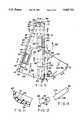
- FIG. 1is a plan view of one mirror image half of a housing employing two such halves snap fitted together showing an initial position of a needle cartridge assembly to the housing according to one embodiment of the present invention
- FIG. 1ais an end elevation view of the housing used in the embodiment of FIG. 1;
- FIG. 2is a view similar to that of FIG. 1 in which the cartridge assembly is in the needle use position;
- FIG. 3is a view similar to that of FIG. 2 wherein the needle cartridge has been displaced to a second position immediately prior to automatic retraction of the needle;
- FIG. 4is a view similar to that of FIG. 3 wherein the needle cartridge has been automatically retracted to a protected position;
- FIGS. 6-13are respective elevation sectional views of the housing half of FIG. 5 taken along respective lines 6--6, 7--7, 8--8, 9--9, 10--10, 11--11, 12--12 and 13--13.
- the chamber 28, FIG. 5,is open to the ambient atmosphere at end 44 forming a second opening 42 opposite end 32.
- the axes 36 and 40pass through both openings 30 and 42 and subtend an angle ⁇ .
- a ramp 60is resiliently cantilevered from bottom wall 24 at ramp end 63 by U-shaped slot 61 in the bottom wall 24.
- Ramp 60has an arcuate bottom surface 62 and extends in the axial direction 64 parallel to axis 36 from end 63.
- the ramp 60 in the quiescent stateinclines upwardly away from bottom wall 24 in a direction 64 toward end 32, FIG. 10, and terminates in shoulder 66 at a ramp end opposite end 63.
- the shoulder 66is planar and generally normal to bottom wall 24 and axis 36.
- the bottom surface 62forms an arcuate channel inclined relative to and generally extending along axis 36. In FIGS. 5, 8 and 10 the surface 62 merges into arcuate bottom surface 68 at end 63.
- An extended depressed arcuate channel 70, FIGS. 5 and 8,is formed in the bottom wall 24.
- the bottom wall 24 surface 71 in chamber 28is depressed with respect to bottom surface 74 forming a tortuous shoulder 76 in the wall 24.
- An second ramp 72lies on axis 40 resiliently cantilevered from bottom wall 24 end 77 in chamber 28, FIGS. 5 and 11.
- the ramp 72is formed by a U-shaped slot 75 in the bottom wall 24 and extends cantilevered from end 77 toward housing 12 end 44.
- the ramp 72has an arcuate channel surface 73, FIG. 11 extending along axis 40 and a shoulder 78 at the ramp end formed by slot 75 on axis 40, FIG. 5.
- the shoulder 78is planar and generally normal to the bottom wall 24 and axis 40.
- Ramp 72is similar to ramp 60 but extends along axis 40 in the generally opposite direction as ramp 60. That is the ramp 72 surface 73 ramps upwardly toward end 44 with shoulder 78 closest to end 44 on the member 72.
- the ramp 72resiliently displaces into the drawing plane of FIG. 5 as does the ramp 60 in response to a normal force in this direction.
- a further arcuate channel 84, FIG. 9is formed in the chamber 28 surface of bottom wall 24.
- Channel 84is aligned on axis 36.
- a triangular shaped cam 85FIG. 5, preferably molded thermoplastic material, has a hinge member 87 which is rotatably secured in a mating hinge opening in wall 20'.
- the cam 85has two pairs of projections 89 and 91, FIG. 12, a pair being on opposite sides which form a recess therebetween which snap fit to projections 99, FIG. 9, in opening 100 of the housing 12 wall 20'. Opening 100 receives the cam 85 in response to rotation of the cam 85 about the hinge member 87 in direction 102, FIG. 5.
- the cam 85has third projections 104 on opposite sides which snap to projections 99, FIG. 9, when the cam is rotated in direction 102.
- assembly 86is axially inserted into chamber 28 of housing 12 through opening 44 along axis 36 until the needle 86 protrudes through the opening 30 at end 32, FIG. 2.
- the body 92 and collar 90slide along and resiliently depress the ramp 60 on the top and bottom walls.
- the body 92rests on the arcuate surface 62 of ramp 60 and is held by the ramp arcuate channel of surface 62 on the axis 36. Recall there are two such ramps on opposite top and bottom walls of the housing 12.
- the collarslides along the ramp depressing the ramp 60 until the collar extends beyond the end of the ramp 60 at shoulder 66. At this position the collar drops into the region next adjacent the bottom wall 24 (and top wall 18).
- the shoulder 94 on the collar 90engage the shoulders 66 on the ramps 60 (on the top and bottom walls) locking the needle 86 in the extended position of FIG. 2, the shoulders 94 and 66 forming respective first and second mating engaged locking devices for axially locking the assembly 86 in the axial position of FIG. 2.
- the spring 96 at this timeis compressed between end 32 and the collar 90 forcing the collar against the shoulder 66. The compressed spring and the shoulders 94 and 66 thus holds and locks the assembly 86 in this axial position.
- the cam 85is rotated in direction 102 until it is in the position of FIG. 3, This displaces the needle assembly 86 into alignment with axis 40 as shown in FIG. 3.
- the assemblycan so displace because the ramp 60 is resiliently depressed in direction 62', FIG. 7, and the body 92 and collar 90 can ride over the lip 61 of the depressed arcuate surface 62 of the ramp 60 and over the lip 91 of the arcuate surface of channel 84, FIGS. 7 and 9.
- the lip 61 of the arcuate surface 62 (FIG. 7) and lip 91 of surface 84 (FIG. 9)are relatively short in height permitting the body 92 to ride over and pass in the space between the lips on the two halves of the top and bottom walls. This action disengages shoulder 94 on the collar from shoulder 66 on the ramp 60.
- the spring 96is still compressed at this time.
- the camming actiondisplaces the assembly 86 over angle ⁇ onto axis 40. This action depresses the ramps 72 on the top and bottom walls.
- the body 92 and collar 90ride over the raised lips of ramp 72 until seated in the arcuate channel 73 of ramp 72 on axis 40.
- the assembly 86thus can not move forward toward end 32 because the collar end 90' is locked to the ramp end 78. Thus, the assembly 86 can not move axially in the forward and rearward directions on axis 40.
- the ramp 72having an arcuate bottom surface 73, FIG. 11, retains the assembly 86 on the axis 40.
Landscapes
- Health & Medical Sciences (AREA)
- Life Sciences & Earth Sciences (AREA)
- Biophysics (AREA)
- Pulmonology (AREA)
- Engineering & Computer Science (AREA)
- Anesthesiology (AREA)
- Biomedical Technology (AREA)
- Heart & Thoracic Surgery (AREA)
- Hematology (AREA)
- Animal Behavior & Ethology (AREA)
- General Health & Medical Sciences (AREA)
- Public Health (AREA)
- Veterinary Medicine (AREA)
- Infusion, Injection, And Reservoir Apparatuses (AREA)
Abstract
Description
This invention relates to needle protective devices, more particularly, protective devices used to protect hypodermic and catheter needles and the like.
Needle protective devices are in wide use. They typically comprise inner and outer cylindrical members with mating locking ribs and grooves and similar locking devices. The locking ribs and grooves temporarily lock the outer protective member in a first mode wherein the needle is exposed and projects from the protective device. This locking position is to preclude the members from accidentally engaging their locking devices in a permanent needle protective locking position prior to use of the needle. Some devices include cylinders which may receive a syringe in a hyperdermic application, may be a vacuum cartridge having a septum which is penetrated by a needle portion inside the bore of a receiving cylinder in a blood collecting application or a catheter used for intravenous purposes.
In a blood collecting unit, a blood collecting needle portion projects beyond the cylinder. When its use is completed the outer cylinder member is axially displaced from an overlying position with the inner member to a position cantilevered from the inner member and locked into a needle protective position.
U.S. Pat. No. 4,894,055 discloses multiple tubular members. U.S. Pat. No. 5,098,382 employs a complex arrangement of multiple components. PCT application WO 89/09076 discloses a device which only partially protects the exposed needle. U.S. Pat. No. 4,966,592 employs a slidable sleeve for receiving a hypodermic syringe. An angularly engagable pin and slot define limits of extension and retraction for use with a syringe. Other devices employ complex lever mechanisms as disclosed in U.S. Pat. Nos. 5,026,356; 4,311,136; and 5,069,667.
The problem recognized by the present invention is that the prior art devices that employ multiple cylindrical members and or complex members may be costly. The present invention recognizes that fewer elements tend to be simpler and more cost effective.
In accordance with an embodiment of the present invention, a needle protective device comprises a needle assembly comprising a needle and a body including first and second locking means, the needle extending from the body along a longitudinal axis. A housing having a chamber receives the body and has a first opening in communication with the chamber along a first axis, the opening is for passing the needle from the received body therethrough. Third locking means are secured to the housing in the chamber along the first axis for engaging the first locking means to retain the body in the chamber on the first axis with the needle projecting through the first opening beyond the housing. Fourth locking means are secured to the housing in the chamber aligned with the first opening on a second axis, the fourth locking means for selectively engaging the first locking means to retain at least a portion of the body and the entire needle within the chamber in response to displacement of the body and needle from alignment with the first axis to the second axis.
In accordance with a further embodiment, body displacement means are movably secured to the housing for displacing the body and needle from the first axis into alignment with the second axis.
In a further embodiment, resilient means resiliently urge the first locking means into engagement with the third and fourth locking means.
In a still further embodiment the housing includes fifth locking means arranged to engage the second locking means on the second axis for axially locking the body in two opposing axial directions.
FIG. 1 is a plan view of one mirror image half of a housing employing two such halves snap fitted together showing an initial position of a needle cartridge assembly to the housing according to one embodiment of the present invention;
FIG. 1a is an end elevation view of the housing used in the embodiment of FIG. 1;
FIG. 2 is a view similar to that of FIG. 1 in which the cartridge assembly is in the needle use position;
FIG. 3 is a view similar to that of FIG. 2 wherein the needle cartridge has been displaced to a second position immediately prior to automatic retraction of the needle;
FIG. 4 is a view similar to that of FIG. 3 wherein the needle cartridge has been automatically retracted to a protected position;
FIG. 5 is an enlarged view of the housing of FIG. 1; and
FIGS. 6-13 are respective elevation sectional views of the housing half of FIG. 5 taken alongrespective lines 6--6, 7--7, 8--8, 9--9, 10--10, 11--11, 12--12 and 13--13.
In FIG. 1,device 10 comprises a housing 12 (only one half being shown in FIG. 1) of trapezoidal shape. Thehousing 12 comprises two mating molded thermoplasticmirror image halves projections 14 onhalf 16 and mating holes (not shown) on theother half 18. Thehousing 12 has abottom wall 24 and atop wall 26. Twoopposite side walls half 16 upstanding frombottom wall 24 andwalls 20" and 22" inhalf 18 depending fromtop wall 26. Thewalls trapezoidal chamber 28 in the housing. Thechamber 28 is in communication with the ambient atmosphere through opening 30 of restricted transverse dimension atend 32 of thehousing 12.
In the following description, the description ofhalf 16 is representative of the othermirror image half 18. In FIG. 5, opening 30 is defined by oneside 34 which is parallel toaxis 36.Side 34 is an extension of wall 20'. Theother side 38 of opening 30 is parallel toaxis 40 and wall 22'. In FIG. 10, thebottom wall 24 has anupstanding portion 48 which forms the bottom surface of the opening 30 which is approximately conical. A step 50 is formed inbottom wall 24 and in the side walls 20' and 22' to couple opening 30 tochamber 28 via enlarged chamber 52 (see also FIG. 6). Wall 22' has ashoulder 29 formed by arecess 31 in the wall 22' inchamber 28.
Thechamber 28, FIG. 5, is open to the ambient atmosphere atend 44 forming a second opening 42opposite end 32. Theaxes openings
In FIGS. 5, 7 and 10, aramp 60 is resiliently cantilevered frombottom wall 24 at ramp end 63 by U-shapedslot 61 in thebottom wall 24.Ramp 60 has anarcuate bottom surface 62 and extends in theaxial direction 64 parallel toaxis 36 from end 63. Theramp 60 in the quiescent state inclines upwardly away frombottom wall 24 in adirection 64 towardend 32, FIG. 10, and terminates inshoulder 66 at a ramp end opposite end 63. Theshoulder 66 is planar and generally normal tobottom wall 24 andaxis 36. Thebottom surface 62 forms an arcuate channel inclined relative to and generally extending alongaxis 36. In FIGS. 5, 8 and 10 thesurface 62 merges intoarcuate bottom surface 68 at end 63. An extended depressedarcuate channel 70, FIGS. 5 and 8, is formed in thebottom wall 24. Thebottom wall 24surface 71 inchamber 28 is depressed with respect tobottom surface 74 forming atortuous shoulder 76 in thewall 24.
Ansecond ramp 72 lies onaxis 40 resiliently cantilevered frombottom wall 24 end 77 inchamber 28, FIGS. 5 and 11. Theramp 72 is formed by a U-shaped slot 75 in thebottom wall 24 and extends cantilevered from end 77 towardhousing 12end 44. Theramp 72 has anarcuate channel surface 73, FIG. 11 extending alongaxis 40 and ashoulder 78 at the ramp end formed by slot 75 onaxis 40, FIG. 5. Theshoulder 78 is planar and generally normal to thebottom wall 24 andaxis 40.Ramp 72 is similar toramp 60 but extends alongaxis 40 in the generally opposite direction asramp 60. That is theramp 72surface 73 ramps upwardly towardend 44 withshoulder 78 closest toend 44 on themember 72. Theramp 72 resiliently displaces into the drawing plane of FIG. 5 as does theramp 60 in response to a normal force in this direction.
A furtherarcuate channel 84, FIG. 9 is formed in thechamber 28 surface ofbottom wall 24.Channel 84 is aligned onaxis 36.
A triangular shapedcam 85, FIG. 5, preferably molded thermoplastic material, has ahinge member 87 which is rotatably secured in a mating hinge opening in wall 20'. Thecam 85 has two pairs ofprojections projections 99, FIG. 9, in opening 100 of thehousing 12 wall 20'.Opening 100 receives thecam 85 in response to rotation of thecam 85 about thehinge member 87 indirection 102, FIG. 5. Thecam 85 hasthird projections 104 on opposite sides which snap toprojections 99, FIG. 9, when the cam is rotated indirection 102.
In FIG. 1,needle assembly 86 comprises ahollow needle 88 extending fromcollar 90 secured tobody 92. The body and collar are circular cylinders with the collar being of larger diameter forming ashoulder 94 with thebody 92. Acompression spring 96 encircles theneedle 88 and abuts the collar.
In operation,assembly 86 is axially inserted intochamber 28 ofhousing 12 throughopening 44 alongaxis 36 until theneedle 86 protrudes through theopening 30 atend 32, FIG. 2. Thebody 92 andcollar 90 slide along and resiliently depress theramp 60 on the top and bottom walls. Thebody 92 rests on thearcuate surface 62 oframp 60 and is held by the ramp arcuate channel ofsurface 62 on theaxis 36. Recall there are two such ramps on opposite top and bottom walls of thehousing 12. In this position, the collar slides along the ramp depressing theramp 60 until the collar extends beyond the end of theramp 60 atshoulder 66. At this position the collar drops into the region next adjacent the bottom wall 24 (and top wall 18). Theshoulder 94 on thecollar 90 engage theshoulders 66 on the ramps 60 (on the top and bottom walls) locking theneedle 86 in the extended position of FIG. 2, theshoulders assembly 86 in the axial position of FIG. 2. Thespring 96 at this time is compressed betweenend 32 and thecollar 90 forcing the collar against theshoulder 66. The compressed spring and theshoulders assembly 86 in this axial position.
After the needle has been used, thecam 85 is rotated indirection 102 until it is in the position of FIG. 3, This displaces theneedle assembly 86 into alignment withaxis 40 as shown in FIG. 3. The assembly can so displace because theramp 60 is resiliently depressed in direction 62', FIG. 7, and thebody 92 andcollar 90 can ride over thelip 61 of the depressedarcuate surface 62 of theramp 60 and over thelip 91 of the arcuate surface ofchannel 84, FIGS. 7 and 9. Thelip 61 of the arcuate surface 62 (FIG. 7) andlip 91 of surface 84 (FIG. 9) are relatively short in height permitting thebody 92 to ride over and pass in the space between the lips on the two halves of the top and bottom walls. This action disengagesshoulder 94 on the collar fromshoulder 66 on theramp 60.
Thespring 96 is still compressed at this time. The camming action displaces theassembly 86 over angle α ontoaxis 40. This action depresses theramps 72 on the top and bottom walls. Thebody 92 andcollar 90 ride over the raised lips oframp 72 until seated in thearcuate channel 73 oframp 72 onaxis 40.
However, since theneedle assembly 86 is no longer held in the axial position of FIG. 3 by the locking action of theshoulders assembly 86 is free to displace rearward towardend 44. Theassembly 86 is urged rearward towardend 44 by thecompressed spring 96. This causes theassembly 86 to displace rearwardly towardend 44 to the position of FIG. 4. In this position, thecollar shoulder 94 engages theshoulder 29 in the wall 22' locking theassembly 86 in this rearward position. Also, thecollar 90 snaps into position beyond thecantilevered end 78 of theramp 72 wherein theramp 72 returns to its original undepressed position. Thecollar 90 via its extended end 90' in this position is locked axially by thecantilevered end 78 of theramp 72. Theassembly 86 thus can not move forward towardend 32 because the collar end 90' is locked to theramp end 78. Thus, theassembly 86 can not move axially in the forward and rearward directions onaxis 40. Theramp 72 having anarcuate bottom surface 73, FIG. 11, retains theassembly 86 on theaxis 40.
It will be appreciated that modifications may be made by one of ordinary skill. It is intended that the detailed description be illustrative and not limiting. The scope of the invention is as defined in the appended claims.
Claims (20)
1. A needle protective device comprising:
a needle assembly comprising a needle and a body including first and second locking means, the needle extending from the body along a longitudinal axis;
a housing having a chamber for receiving the body and having a first opening in communication with the chamber along a first axis, the opening for passing the needle from the received body therethrough;
third locking means secured to the housing in the chamber along the first axis for engaging the first locking means to retain the body in the chamber on the first axis with the needle projecting through the first opening beyond the housing; and
fourth locking means secured to the housing in the chamber aligned with the first opening on a second axis, the fourth locking means for selectively engaging the first locking means to retain at least a portion of the body and the entire needle within the chamber in response to displacement of the body and needle from alignment with the first axis to the second axis.
2. The device of claim 1 including body displacement means movably secured to the housing for displacing the body and needle from the first axis into alignment with the second axis.
3. The device of claim 2 including resilient means for resiliently urging the first locking means into engagement with the third and fourth locking means.
4. The device of claim I wherein the housing includes fifth locking means arranged to engage the second locking means for locking the needle assembly in opposing axial directions on the second axis.
5. The device of claim 4 wherein the resilient means comprises a compression spring for receiving the needle therethrough such that the spring compresses when the body is on the first axis and expands to push the body away from the first opening and needle out of the first opening along the second axis and into the chamber.
6. The device of claim 1 wherein the first locking means comprises a first shoulder on the body lying in a plane transverse the needle longitudinal axis, and the second locking means comprises a second shoulder on the body, the third and fourth locking means each comprise an abutment secured to the housing and arranged to mate with and engage the first shoulder.
7. The device of claim 1 wherein the body is a circular cylindrical member and the first and second locking means comprises a circular cylindrical collar on the member of larger diameter than the member.
8. The device of claim 6 including fifth locking means secured to the housing, wherein the third and fifth locking means each comprise angularly spaced ramps for axially resiliently receiving the body, the third and fifth locking means comprising a locking shoulder for respectively engaging the body first and second locking means in axial locking engagement.
9. The device of claim 7 wherein the ramps have arcuate body receiving surfaces and are cantilevered from the housing in an axial direction for resilient displacement.
10. The device of claim 2 including means responsive to the displacement of the body from the first to second axes for automatically retracting the needle out of the first opening into the chamber wherein the first locking means disengages the third locking means and engages the fourth locking means,
11. The device of claim 1 wherein the housing has a second opening aligned on and between the first and second axes for receiving the needle and body therethrough on the first axis.
12. The device of claim 2 wherein the displacement means comprises a cam member pivotally secured to the housing for displacement to first and second positions and including means for engaging the body in the first position and manually pushing the body to the second axis when displaced to the second position.
13. The device of claim 12 wherein the cam member is triangular with one apex of the triangle pivotally secured to the housing.
14. The device of claim 13 wherein a second apex of the member and the housing includes further mating locking means for temporarily securing the member to the housing in the first and second positions,
15. The device of claim 8 wherein the ramps form respective channels inclined relative to the corresponding first and second axes.
16. The device of claim 15 wherein the channels are arcuate depressions extending along the corresponding first and second axes.
17. A needle protective device comprising:
a needle assembly comprising a needle and a body including first and second locking means, the needle extending from the body along a longitudinal axis;
a housing having a chamber for receiving the body and having a first opening in communication with the chamber along a first axis, the opening for passing the needle from the received body therethrough, said housing having a second opening for receiving the assembly therethrough on the first axis to place the body in said chamber;
third locking means secured to the housing in the chamber along the first axis for engaging the first locking means to retain the body in the chamber on the first axis with the needle projecting through the first opening beyond the housing;
fourth and fifth locking means secured to the housing in the chamber aligned with the first opening on a second different axis, the fourth locking means for selectively engaging the first locking means and the fifth locking means selectively engaging the second locking means to retain at least a portion of the body and the entire needle within the chamber in response to displacement of the body and needle from alignment with the first axis to the second axis; and
body displacement means movably secured to the housing for displacing the body and needle from the first axis into alignment with the second axis.
18. The device of claim 17 including resilient means for resiliently urging the first and second locking means into engagement with the respective corresponding fourth and fifth locking means.
19. The device of claim 18 wherein the second opening subtends an angular extent including the first and second axes, said body protruding from the second opening when on the second axis.
20. A needle protective device comprising:
a needle assembly comprising a needle and a circular cylindrical elongated hollow core body, said body forming first and second locking means, the needle extending from the body core along a longitudinal axis;
a housing having a chamber for receiving the body along a first axis and having a first opening in communication with the chamber along the first axis, the opening having a restricted transverse dimension for passing only the needle from the received body therethrough, said housing having a second opening for receiving the assembly therethrough on the first axis to place at least a portion of the body in said chamber;
third locking means comprising a projection in the chamber secured to the housing along the first axis for engaging the first locking means to retain the body in the chamber on the first axis with the needle projecting through the first opening beyond the housing;
fourth and fifth locking means in the chamber aligned with the first opening on a second axis, the fourth locking means for selectively engaging the first locking means and the fifth locking means for selectively engaging the second locking means to lock in opposing axial directions at least a portion of the body and the entire needle within the chamber in response to displacement of the body and needle from alignment on the first axis to the second axis;
a spring surrounding the needle and engaged with the received body and housing at said first opening for urging the first locking means in engagement with the third and fourth locking means; and
body displacement means movably secured to the housing for manually displacing the body and needle from the first axis into alignment with the second axis such that the spring automatically causes the first locking means to engage the third locking means and the needle to retract into the housing chamber.
Priority Applications (1)
| Application Number | Priority Date | Filing Date | Title |
|---|---|---|---|
| US08/308,382US5425721A (en) | 1994-09-19 | 1994-09-19 | Needle protective device |
Applications Claiming Priority (1)
| Application Number | Priority Date | Filing Date | Title |
|---|---|---|---|
| US08/308,382US5425721A (en) | 1994-09-19 | 1994-09-19 | Needle protective device |
Publications (1)
| Publication Number | Publication Date |
|---|---|
| US5425721Atrue US5425721A (en) | 1995-06-20 |
Family
ID=23193774
Family Applications (1)
| Application Number | Title | Priority Date | Filing Date |
|---|---|---|---|
| US08/308,382Expired - LifetimeUS5425721A (en) | 1994-09-19 | 1994-09-19 | Needle protective device |
Country Status (1)
| Country | Link |
|---|---|
| US (1) | US5425721A (en) |
Cited By (15)
| Publication number | Priority date | Publication date | Assignee | Title |
|---|---|---|---|---|
| US5695476A (en)* | 1993-11-09 | 1997-12-09 | Harris; Ivan Paul | Needle protection assemblies |
| US5879337A (en)* | 1997-02-27 | 1999-03-09 | Injectimed, Inc. | Needle tip guard for hypodermic needles |
| CN1061922C (en)* | 1996-01-11 | 2001-02-14 | 布克刀具股份有限公司 | Combination tool with oppositely deploying handles |
| US6443929B1 (en) | 1996-02-27 | 2002-09-03 | Injectimed, Inc. | Needle tip guard for hypodermic needles |
| US20040204678A1 (en)* | 2000-01-27 | 2004-10-14 | Afra Design Pty. Limited. | Single-use syringe |
| US6860871B2 (en) | 2001-04-30 | 2005-03-01 | Injectimed, Inc. | Needle tip guard for percutaneous entry needles |
| US20090216201A1 (en)* | 2007-11-21 | 2009-08-27 | Becton, Dickinson And Company | Safety Needle Guard |
| US20110040281A1 (en)* | 2009-08-14 | 2011-02-17 | White Steven B | Integrated vascular delivery system |
| US8273056B2 (en) | 2011-02-28 | 2012-09-25 | Injectimed, Inc. | Needle guard with resilient spring surrounding tip shield |
| US8414539B1 (en) | 2011-12-27 | 2013-04-09 | B. Braun Melsungen Ag | Needle tip guard for percutaneous entry needles |
| US8672895B2 (en) | 2011-02-28 | 2014-03-18 | Injectimed, Inc. | Needle guard |
| US8771230B2 (en) | 2010-05-19 | 2014-07-08 | Tangent Medical Technologies, Llc | Integrated vascular delivery system |
| US8814833B2 (en) | 2010-05-19 | 2014-08-26 | Tangent Medical Technologies Llc | Safety needle system operable with a medical device |
| US9278180B2 (en) | 2007-11-21 | 2016-03-08 | Becton, Dickinson And Company | Needle safety device |
| US10086170B2 (en) | 2014-02-04 | 2018-10-02 | Icu Medical, Inc. | Self-priming systems and methods |
Citations (4)
| Publication number | Priority date | Publication date | Assignee | Title |
|---|---|---|---|---|
| US5295974A (en)* | 1991-01-07 | 1994-03-22 | Laughlin D Michael O | Shielded hypodermic needle with I.V. cannula |
| US5336199A (en)* | 1993-11-12 | 1994-08-09 | Castillo Leo S | Medical needle and needle sheath assembly |
| US5360408A (en)* | 1992-11-16 | 1994-11-01 | Vaillancourt Vincent L | Shielded hypodermic needle assembly and a shield assembly for a hypodermic needle |
| US5368568A (en)* | 1993-10-12 | 1994-11-29 | Pitts; Raymond H. | Disabling hypodermic syringe |
- 1994
- 1994-09-19USUS08/308,382patent/US5425721A/ennot_activeExpired - Lifetime
Patent Citations (4)
| Publication number | Priority date | Publication date | Assignee | Title |
|---|---|---|---|---|
| US5295974A (en)* | 1991-01-07 | 1994-03-22 | Laughlin D Michael O | Shielded hypodermic needle with I.V. cannula |
| US5360408A (en)* | 1992-11-16 | 1994-11-01 | Vaillancourt Vincent L | Shielded hypodermic needle assembly and a shield assembly for a hypodermic needle |
| US5368568A (en)* | 1993-10-12 | 1994-11-29 | Pitts; Raymond H. | Disabling hypodermic syringe |
| US5336199A (en)* | 1993-11-12 | 1994-08-09 | Castillo Leo S | Medical needle and needle sheath assembly |
Cited By (47)
| Publication number | Priority date | Publication date | Assignee | Title |
|---|---|---|---|---|
| US5695476A (en)* | 1993-11-09 | 1997-12-09 | Harris; Ivan Paul | Needle protection assemblies |
| CN1061922C (en)* | 1996-01-11 | 2001-02-14 | 布克刀具股份有限公司 | Combination tool with oppositely deploying handles |
| US8545454B2 (en) | 1996-02-27 | 2013-10-01 | B. Braun Melsungen Ag | Needle tip guard for percutaneous entry needles |
| US20110166526A1 (en)* | 1996-02-27 | 2011-07-07 | B. Braun Melsungen Ag | Needle tip guard for percutaneous entry needles |
| US6443929B1 (en) | 1996-02-27 | 2002-09-03 | Injectimed, Inc. | Needle tip guard for hypodermic needles |
| US20060189934A1 (en)* | 1996-02-27 | 2006-08-24 | Kuracina Thomas C | Needle tip guard for percutaneous entry needles |
| US7534231B2 (en) | 1996-02-27 | 2009-05-19 | Injectimed, Inc. | Needle tip guard for percutaneous entry needles |
| US20090177167A1 (en)* | 1996-02-27 | 2009-07-09 | Thomas Kuracina | Needle tip guard for percutaneous entry needles |
| US20100137815A1 (en)* | 1996-02-27 | 2010-06-03 | Kuracina Thomas C | Needle tip guard for percutaneous entry needles |
| US8444605B2 (en) | 1996-02-27 | 2013-05-21 | B. Braun Melsungen Ag | Needle tip guard for percutaneous entry needles |
| US7927314B2 (en) | 1996-02-27 | 2011-04-19 | B. Bran Melsungen AG | Needle tip guard for percutaneous entry needles |
| US5879337A (en)* | 1997-02-27 | 1999-03-09 | Injectimed, Inc. | Needle tip guard for hypodermic needles |
| US6001080A (en)* | 1997-02-27 | 1999-12-14 | Injectimed, Inc. | Intravenous catheter assembly |
| US20040204678A1 (en)* | 2000-01-27 | 2004-10-14 | Afra Design Pty. Limited. | Single-use syringe |
| US6997901B2 (en) | 2000-01-27 | 2006-02-14 | Biomd Limited | Single-use syringe |
| US6860871B2 (en) | 2001-04-30 | 2005-03-01 | Injectimed, Inc. | Needle tip guard for percutaneous entry needles |
| US8298180B2 (en) | 2007-11-21 | 2012-10-30 | Becton, Dickinson And Company | Safety needle guard |
| US20090216201A1 (en)* | 2007-11-21 | 2009-08-27 | Becton, Dickinson And Company | Safety Needle Guard |
| US9278180B2 (en) | 2007-11-21 | 2016-03-08 | Becton, Dickinson And Company | Needle safety device |
| US12370348B2 (en) | 2009-08-14 | 2025-07-29 | The Regents Of The University Of Michigan | Integrated vascular delivery system |
| US11577053B2 (en) | 2009-08-14 | 2023-02-14 | The Regents Of The University Of Michigan | Integrated vascular delivery system |
| US20110040281A1 (en)* | 2009-08-14 | 2011-02-17 | White Steven B | Integrated vascular delivery system |
| US10668252B2 (en) | 2009-08-14 | 2020-06-02 | The Regents Of The University Of Michigan | Integrated vascular delivery system |
| US9962526B2 (en) | 2009-08-14 | 2018-05-08 | The Regents Of The University Of Michigan | Integrated vascular delivery system |
| US9592366B2 (en) | 2009-08-14 | 2017-03-14 | The Regents Of The University Of Michigan | Integrated vascular delivery system |
| US9827398B2 (en) | 2010-05-19 | 2017-11-28 | Tangent Medical Technologies, Inc. | Integrated vascular delivery system |
| US10159818B2 (en) | 2010-05-19 | 2018-12-25 | Tangent Medical Technologies, Inc. | Safety needle system operable with a medical device |
| US12059538B2 (en) | 2010-05-19 | 2024-08-13 | Tangent Medical Technologies, Inc. | Safety needle system operable with a medical device |
| US9308354B2 (en) | 2010-05-19 | 2016-04-12 | Tangent Medical Technologies Llc | Safety needle system operable with a medical device |
| US11577052B2 (en) | 2010-05-19 | 2023-02-14 | Tangent Medical Technologies, Inc. | Integrated vascular delivery system |
| US10905858B2 (en) | 2010-05-19 | 2021-02-02 | Tangent Medical Technologies, Inc. | Safety needle system operable with a medical device |
| US8814833B2 (en) | 2010-05-19 | 2014-08-26 | Tangent Medical Technologies Llc | Safety needle system operable with a medical device |
| US10569057B2 (en) | 2010-05-19 | 2020-02-25 | Tangent Medical Technologies, Inc. | Integrated vascular delivery system |
| US8771230B2 (en) | 2010-05-19 | 2014-07-08 | Tangent Medical Technologies, Llc | Integrated vascular delivery system |
| US9440052B2 (en) | 2011-02-28 | 2016-09-13 | Injectimed, Inc. | Needle guard |
| US9238104B2 (en) | 2011-02-28 | 2016-01-19 | Injectimed, Inc. | Needle guard |
| US9610403B2 (en) | 2011-02-28 | 2017-04-04 | Injectimed, Inc. | Needle guard |
| US8672895B2 (en) | 2011-02-28 | 2014-03-18 | Injectimed, Inc. | Needle guard |
| US8764711B2 (en) | 2011-02-28 | 2014-07-01 | Injectimed, Inc. | Needle guard |
| US11344671B2 (en) | 2011-02-28 | 2022-05-31 | Injectimed, Inc. | Needle guard |
| US9399119B2 (en) | 2011-02-28 | 2016-07-26 | Injectimed, Inc. | Needle guard |
| US8821439B2 (en) | 2011-02-28 | 2014-09-02 | Injectimed Inc. | Needle guard |
| US8273056B2 (en) | 2011-02-28 | 2012-09-25 | Injectimed, Inc. | Needle guard with resilient spring surrounding tip shield |
| US8414539B1 (en) | 2011-12-27 | 2013-04-09 | B. Braun Melsungen Ag | Needle tip guard for percutaneous entry needles |
| US10086170B2 (en) | 2014-02-04 | 2018-10-02 | Icu Medical, Inc. | Self-priming systems and methods |
| US10814107B2 (en) | 2014-02-04 | 2020-10-27 | Icu Medical, Inc. | Self-priming systems and methods |
| US11724071B2 (en) | 2014-02-04 | 2023-08-15 | Icu Medical, Inc. | Self-priming systems and methods |
Similar Documents
| Publication | Publication Date | Title |
|---|---|---|
| US5425721A (en) | Needle protective device | |
| US5295965A (en) | Automatic injectors | |
| CA2447944C (en) | Needle shield assembly having hinged needle shield | |
| CA2440898C (en) | Improved non-reusable syringe | |
| US5390571A (en) | Push button socket locking mechanism | |
| US5531694A (en) | Needle retraction system | |
| US6835190B2 (en) | Retractable safety infusion needle | |
| JP2592749B2 (en) | Injection needle automatic retractable protective equipment | |
| US6077253A (en) | Safety needle assembly | |
| EP0620748B1 (en) | Automatic injectors | |
| US8313463B2 (en) | Injection device | |
| US5395337A (en) | Needle retraction system | |
| US5346480A (en) | Syringe with retractable needle | |
| CA2007628C (en) | Releasable coupling or attachment device | |
| AU720142B2 (en) | Safety syringe | |
| JPH05245211A (en) | Monolithic composite connector especially for medical liquid circuit | |
| US5279584A (en) | Rotary lock for needle sheaths | |
| CA2430935A1 (en) | Pen-type injector having holding mechanism for medicament cartridge | |
| JPH05161712A (en) | Injector | |
| TW336897B (en) | Retractable needle and syringe combination | |
| JPH0773068B2 (en) | Connector with locking mechanism | |
| CN101287512A (en) | Needle shield assembly | |
| US6371941B1 (en) | Prefilled syringe | |
| US6210374B1 (en) | Needle protective sheath device | |
| EP0317518B1 (en) | Needle protector device for syringe. |
Legal Events
| Date | Code | Title | Description |
|---|---|---|---|
| STCF | Information on status: patent grant | Free format text:PATENTED CASE | |
| FEPP | Fee payment procedure | Free format text:PAYOR NUMBER ASSIGNED (ORIGINAL EVENT CODE: ASPN); ENTITY STATUS OF PATENT OWNER: SMALL ENTITY | |
| REFU | Refund | Free format text:REFUND - PAYMENT OF MAINTENANCE FEE, 4TH YR, SMALL ENTITY (ORIGINAL EVENT CODE: R283); ENTITY STATUS OF PATENT OWNER: SMALL ENTITY | |
| FPAY | Fee payment | Year of fee payment:4 | |
| FPAY | Fee payment | Year of fee payment:8 | |
| REMI | Maintenance fee reminder mailed | ||
| AS | Assignment | Owner name:FINANCIAL FEDERAL CREDIT INC., TEXAS Free format text:ASSIGNMENT OF ASSIGNORS INTEREST;ASSIGNOR:MEDISAFE GUARD PRODUCTS, INC;REEL/FRAME:016446/0859 Effective date:20050315 | |
| REMI | Maintenance fee reminder mailed | ||
| AS | Assignment | Owner name:U.S.SAFETY SYRINGES CO., INC., CALIFORNIA Free format text:ASSIGNMENT OF ASSIGNORS INTEREST;ASSIGNOR:FINANCIAL FEDERAL CREDIT, INC.;REEL/FRAME:019304/0272 Effective date:20060208 | |
| FPAY | Fee payment | Year of fee payment:12 | |
| SULP | Surcharge for late payment | Year of fee payment:11 |