US5425327A - Boat canopy mounting system - Google Patents
Boat canopy mounting systemDownload PDFInfo
- Publication number
- US5425327A US5425327AUS08/213,992US21399294AUS5425327AUS 5425327 AUS5425327 AUS 5425327AUS 21399294 AUS21399294 AUS 21399294AUS 5425327 AUS5425327 AUS 5425327A
- Authority
- US
- United States
- Prior art keywords
- boat
- canopy
- locking
- channel
- header
- Prior art date
- Legal status (The legal status is an assumption and is not a legal conclusion. Google has not performed a legal analysis and makes no representation as to the accuracy of the status listed.)
- Expired - Lifetime
Links
- 238000003825pressingMethods0.000claimsabstractdescription6
- 238000003780insertionMethods0.000claimsabstractdescription5
- 230000037431insertionEffects0.000claimsabstractdescription5
- 229910052782aluminiumInorganic materials0.000claimsdescription4
- XAGFODPZIPBFFR-UHFFFAOYSA-NaluminiumChemical compound[Al]XAGFODPZIPBFFR-UHFFFAOYSA-N0.000claimsdescription4
- 229920003023plasticPolymers0.000claimsdescription3
- 239000004033plasticSubstances0.000claimsdescription3
- 238000000034methodMethods0.000description4
- 239000000463materialSubstances0.000description3
- 230000000712assemblyEffects0.000description2
- 238000000429assemblyMethods0.000description2
- -1for exampleSubstances0.000description2
- 230000013011matingEffects0.000description2
- 239000004698PolyethyleneSubstances0.000description1
- 238000005260corrosionMethods0.000description1
- 230000007797corrosionEffects0.000description1
- 238000001125extrusionMethods0.000description1
- 239000004744fabricSubstances0.000description1
- 239000011152fibreglassSubstances0.000description1
- 229920002457flexible plasticPolymers0.000description1
- 238000009434installationMethods0.000description1
- 230000003993interactionEffects0.000description1
- 230000005923long-lasting effectEffects0.000description1
- 230000014759maintenance of locationEffects0.000description1
- 229910052751metalInorganic materials0.000description1
- 239000002184metalSubstances0.000description1
- 150000002739metalsChemical class0.000description1
- 229920000573polyethylenePolymers0.000description1
- 229920002635polyurethanePolymers0.000description1
- 239000004814polyurethaneSubstances0.000description1
- 229920000915polyvinyl chloridePolymers0.000description1
- 239000004800polyvinyl chlorideSubstances0.000description1
- 230000000452restraining effectEffects0.000description1
- 229910001220stainless steelInorganic materials0.000description1
- 239000010935stainless steelSubstances0.000description1
- 238000003466weldingMethods0.000description1
Images

Classifications
- B—PERFORMING OPERATIONS; TRANSPORTING
- B63—SHIPS OR OTHER WATERBORNE VESSELS; RELATED EQUIPMENT
- B63B—SHIPS OR OTHER WATERBORNE VESSELS; EQUIPMENT FOR SHIPPING
- B63B17/00—Vessels parts, details, or accessories, not otherwise provided for
- B63B17/02—Awnings, including rigid weather protection structures, e.g. sunroofs; Tarpaulins; Accessories for awnings or tarpaulins
- A—HUMAN NECESSITIES
- A44—HABERDASHERY; JEWELLERY
- A44B—BUTTONS, PINS, BUCKLES, SLIDE FASTENERS, OR THE LIKE
- A44B19/00—Slide fasteners
- A44B19/10—Slide fasteners with a one-piece interlocking member on each stringer tape
- A44B19/16—Interlocking member having uniform section throughout the length of the stringer
Definitions
- Lewisis similar to Singleton in that it requires the lateral edge of the canopy to be tucked underneath the header into a groove, a similarly tedious process.
- Lewisdiscloses a header that fits on the edge of the boat's windshield and extends outwardly and forwardly of the windshield.
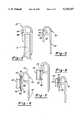
- a locking channelis formed underneath the outwardly protruding header and includes a rounded portion, an accurate portion and a arcuately shaped lip.
- a second channelis formed forwardly of the locking channel. This second channel includes a rounded portion, an arcuately shaped lip and a downwardly facing shoulder.
- a flexible locking stripis provided for insertion into the locking channel and the second channel.
- the flexible striphas a generally arcuate portion ending in a downwardly turned lip portion and an inwardly projecting rib.
- FIG. 2is a cross-sectional view of the snapless fastener system of the present system taken along line 2--2 of FIG. 1.
- FIG. 7is a cross-sectional view of a further embodiment of the header of the present invention employing a snap.
Landscapes
- Chemical & Material Sciences (AREA)
- Engineering & Computer Science (AREA)
- Combustion & Propulsion (AREA)
- Mechanical Engineering (AREA)
- Ocean & Marine Engineering (AREA)
- Connection Of Plates (AREA)
Abstract
Description
Claims (17)
Priority Applications (2)
| Application Number | Priority Date | Filing Date | Title |
|---|---|---|---|
| US08/213,992US5425327A (en) | 1992-07-15 | 1994-03-14 | Boat canopy mounting system |
| US08/422,154US5622136A (en) | 1992-07-15 | 1995-04-14 | Boat canopy mounting system |
Applications Claiming Priority (2)
| Application Number | Priority Date | Filing Date | Title |
|---|---|---|---|
| US91424792A | 1992-07-15 | 1992-07-15 | |
| US08/213,992US5425327A (en) | 1992-07-15 | 1994-03-14 | Boat canopy mounting system |
Related Parent Applications (1)
| Application Number | Title | Priority Date | Filing Date |
|---|---|---|---|
| US91424792AContinuation | 1992-07-15 | 1992-07-15 |
Related Child Applications (1)
| Application Number | Title | Priority Date | Filing Date |
|---|---|---|---|
| US08/422,154ContinuationUS5622136A (en) | 1992-07-15 | 1995-04-14 | Boat canopy mounting system |
Publications (1)
| Publication Number | Publication Date |
|---|---|
| US5425327Atrue US5425327A (en) | 1995-06-20 |
Family
ID=25434079
Family Applications (2)
| Application Number | Title | Priority Date | Filing Date |
|---|---|---|---|
| US08/213,992Expired - LifetimeUS5425327A (en) | 1992-07-15 | 1994-03-14 | Boat canopy mounting system |
| US08/422,154Expired - LifetimeUS5622136A (en) | 1992-07-15 | 1995-04-14 | Boat canopy mounting system |
Family Applications After (1)
| Application Number | Title | Priority Date | Filing Date |
|---|---|---|---|
| US08/422,154Expired - LifetimeUS5622136A (en) | 1992-07-15 | 1995-04-14 | Boat canopy mounting system |
Country Status (1)
| Country | Link |
|---|---|
| US (2) | US5425327A (en) |
Cited By (13)
| Publication number | Priority date | Publication date | Assignee | Title |
|---|---|---|---|---|
| USD369584S (en) | 1995-07-27 | 1996-05-07 | Anchor Industries, Inc. | Watercraft |
| US5622136A (en)* | 1992-07-15 | 1997-04-22 | Aldon Industries, Inc. | Boat canopy mounting system |
| US6006692A (en)* | 1998-01-28 | 1999-12-28 | Szukhent, Jr.; Steve | Boat canopy mounting apparatus |
| US6026761A (en)* | 1997-01-31 | 2000-02-22 | Taylor Made Systems Bradenton, Inc. | Canopy mounting system |
| US20020020337A1 (en)* | 2000-08-17 | 2002-02-21 | Bombardier Motor Corporation Of America | Extrusion for boat windshield |
| US20050183652A1 (en)* | 2003-10-27 | 2005-08-25 | Whited Sherman E.Ii | Boat windshield canvas attachment apparatus |
| US20070074648A1 (en)* | 2005-09-30 | 2007-04-05 | Ameritex Technologies, Inc. | System for attaching a flexible enclosure to a boat windshield frame |
| US20100031865A1 (en)* | 2008-08-11 | 2010-02-11 | Ameritex Technologies, Inc. | System for attaching a flexible cover and an edge clip for the same |
| US9556640B2 (en) | 2014-04-25 | 2017-01-31 | Designer Direct, Inc. | Cantilevered watercraft canopy |
| US9776687B2 (en) | 2015-06-19 | 2017-10-03 | Designer Direct, Inc. | One-sided cantilevered watercraft canopy |
| US10272971B2 (en) | 2015-06-19 | 2019-04-30 | Designer Direct, Inc. | Watercraft canopy for U-shaped dock |
| US11098846B2 (en)* | 2017-07-31 | 2021-08-24 | Taylor Made Group, Llc | Pontoon canvas clip |
| US11952781B2 (en) | 2022-01-27 | 2024-04-09 | Designer Direct, Inc. | Watercraft canopy extension for existing covered dock |
Families Citing this family (4)
| Publication number | Priority date | Publication date | Assignee | Title |
|---|---|---|---|---|
| USD407366S (en) | 1998-04-20 | 1999-03-30 | Badsey William J | Boat |
| US6082358A (en)* | 1998-05-05 | 2000-07-04 | 1263152 Ontario Inc. | Indicating device for aerosol container |
| US7159531B2 (en)* | 2005-04-19 | 2007-01-09 | Lear Baylor, Inc. | Boat system |
| US20100218714A1 (en)* | 2008-09-29 | 2010-09-02 | Withers Charles Robert | Sun screen apparatus for a boat |
Citations (34)
| Publication number | Priority date | Publication date | Assignee | Title |
|---|---|---|---|---|
| US622220A (en)* | 1899-04-04 | Laird goldsborough | ||
| US2937652A (en)* | 1958-09-08 | 1960-05-24 | Nelson A Taylor Co Inc | Means for detachably fastening a flexible top to a windshield |
| US2961725A (en)* | 1959-04-16 | 1960-11-29 | Mcgee Richard | Fastening device |
| US2975496A (en)* | 1959-05-14 | 1961-03-21 | W J Mcgraw | Closure device |
| US3038225A (en)* | 1960-05-27 | 1962-06-12 | Ausnit Steven | Separable fastener |
| US3068939A (en)* | 1959-10-20 | 1962-12-18 | Nat Distillers Chem Corp | Frame for mounting plastic film |
| US3172419A (en)* | 1963-01-31 | 1965-03-09 | Lone Star Boat Company | Canopy lock for boats |
| US3345709A (en)* | 1966-01-12 | 1967-10-10 | Space Ad Company | Selectively engageable and disengageable fastener means |
| GB1092452A (en)* | 1963-11-23 | 1967-11-22 | Margarete Jaster | Strip fastener |
| US3364530A (en)* | 1966-06-08 | 1968-01-23 | Flexigrip Inc | Swallow tail flexible fastener |
| USRE26363E (en)* | 1968-03-12 | Fabric cover for boats | ||
| US3373464A (en)* | 1965-03-30 | 1968-03-19 | Ausnit Steven | Structure for anchoring flexible sheeting |
| US3486788A (en)* | 1967-10-23 | 1969-12-30 | Kayline Mfg Inc | Demountable top fastener device |
| US3595949A (en)* | 1968-01-16 | 1971-07-27 | Flexigrip Inc | Method of making plastic fastener profile |
| US3918131A (en)* | 1974-01-07 | 1975-11-11 | Steven Ausnit | Fluid-tight fastener |
| US4046408A (en)* | 1973-08-03 | 1977-09-06 | Steven Ausnit | Omni-directional fastener |
| US4074492A (en)* | 1975-12-31 | 1978-02-21 | Star Manufacturing Co. Of Oklahoma | Prefabricated watertight structural system |
| US4199845A (en)* | 1978-02-08 | 1980-04-29 | Minigrip, Inc. | Slider for heavy duty flexible fastener tracks |
| US4268938A (en)* | 1979-07-23 | 1981-05-26 | Enviropak Inc. | Closure device for container |
| US4354541A (en)* | 1979-09-13 | 1982-10-19 | Minigrip, Inc. | Profiled plastics bag closure strip and adhesive bonding method |
| US4372014A (en)* | 1975-12-31 | 1983-02-08 | Star Manufacturing Co. | Construction system and fastener therefore |
| US4578813A (en)* | 1984-06-11 | 1986-03-25 | Minigrip Incorporated | Bag and reclosable separable fastener assembly providing both closing alignment facility and differential separation resistance |
| US4660259A (en)* | 1986-08-01 | 1987-04-28 | Minigrip, Inc. | Twist resistant reclosable extruded plastic fastener |
| US4673383A (en)* | 1985-11-12 | 1987-06-16 | Minigrip, Incorporated | Fusible rib bonding of fasteners to substrate |
| US4731911A (en)* | 1986-08-08 | 1988-03-22 | Minigrip, Inc. | Extruded closure strip carrying reactivatable adhesive layer |
| US4787880A (en)* | 1985-12-23 | 1988-11-29 | Minigrip, Inc. | Method of making extruded zipper strips and bags containing the same |
| US4792240A (en)* | 1986-12-23 | 1988-12-20 | Minigrip, Inc. | Extruded zipper strips for bags |
| US4846585A (en)* | 1988-01-29 | 1989-07-11 | Minigrip, Inc. | Easy open bag structure |
| US4878763A (en)* | 1988-11-30 | 1989-11-07 | Minigrip, Inc. | Double hinge zipper construction |
| US4898492A (en)* | 1986-03-17 | 1990-02-06 | Gefrem | Pressure closing device for joining the edges of plastic sheets |
| US4939819A (en)* | 1989-06-28 | 1990-07-10 | The Bentley-Harris Manufacturing Company | Wraparound closure device |
| US4944072A (en)* | 1988-06-25 | 1990-07-31 | Robson Peter M | Profiled fasteners |
| US5070584A (en)* | 1990-03-09 | 1991-12-10 | Dowbrands Inc. | Zipper for a reclosable thermoplastic bag and a process and apparatus for making |
| US5215032A (en)* | 1991-11-19 | 1993-06-01 | Ray Industries, Inc. | System, apparatus and method for rapidly attaching a boat cover or canopy to a windshield |
Family Cites Families (2)
| Publication number | Priority date | Publication date | Assignee | Title |
|---|---|---|---|---|
| US5367977A (en)* | 1991-11-19 | 1994-11-29 | Ray Industries, Inc. | System, apparatus and method for rapidly attaching a boat cover or canopy to a windshield and frame |
| US5425327A (en)* | 1992-07-15 | 1995-06-20 | Aldon Industries, Inc. | Boat canopy mounting system |
- 1994
- 1994-03-14USUS08/213,992patent/US5425327A/ennot_activeExpired - Lifetime
- 1995
- 1995-04-14USUS08/422,154patent/US5622136A/ennot_activeExpired - Lifetime
Patent Citations (34)
| Publication number | Priority date | Publication date | Assignee | Title |
|---|---|---|---|---|
| US622220A (en)* | 1899-04-04 | Laird goldsborough | ||
| USRE26363E (en)* | 1968-03-12 | Fabric cover for boats | ||
| US2937652A (en)* | 1958-09-08 | 1960-05-24 | Nelson A Taylor Co Inc | Means for detachably fastening a flexible top to a windshield |
| US2961725A (en)* | 1959-04-16 | 1960-11-29 | Mcgee Richard | Fastening device |
| US2975496A (en)* | 1959-05-14 | 1961-03-21 | W J Mcgraw | Closure device |
| US3068939A (en)* | 1959-10-20 | 1962-12-18 | Nat Distillers Chem Corp | Frame for mounting plastic film |
| US3038225A (en)* | 1960-05-27 | 1962-06-12 | Ausnit Steven | Separable fastener |
| US3172419A (en)* | 1963-01-31 | 1965-03-09 | Lone Star Boat Company | Canopy lock for boats |
| GB1092452A (en)* | 1963-11-23 | 1967-11-22 | Margarete Jaster | Strip fastener |
| US3373464A (en)* | 1965-03-30 | 1968-03-19 | Ausnit Steven | Structure for anchoring flexible sheeting |
| US3345709A (en)* | 1966-01-12 | 1967-10-10 | Space Ad Company | Selectively engageable and disengageable fastener means |
| US3364530A (en)* | 1966-06-08 | 1968-01-23 | Flexigrip Inc | Swallow tail flexible fastener |
| US3486788A (en)* | 1967-10-23 | 1969-12-30 | Kayline Mfg Inc | Demountable top fastener device |
| US3595949A (en)* | 1968-01-16 | 1971-07-27 | Flexigrip Inc | Method of making plastic fastener profile |
| US4046408A (en)* | 1973-08-03 | 1977-09-06 | Steven Ausnit | Omni-directional fastener |
| US3918131A (en)* | 1974-01-07 | 1975-11-11 | Steven Ausnit | Fluid-tight fastener |
| US4074492A (en)* | 1975-12-31 | 1978-02-21 | Star Manufacturing Co. Of Oklahoma | Prefabricated watertight structural system |
| US4372014A (en)* | 1975-12-31 | 1983-02-08 | Star Manufacturing Co. | Construction system and fastener therefore |
| US4199845A (en)* | 1978-02-08 | 1980-04-29 | Minigrip, Inc. | Slider for heavy duty flexible fastener tracks |
| US4268938A (en)* | 1979-07-23 | 1981-05-26 | Enviropak Inc. | Closure device for container |
| US4354541A (en)* | 1979-09-13 | 1982-10-19 | Minigrip, Inc. | Profiled plastics bag closure strip and adhesive bonding method |
| US4578813A (en)* | 1984-06-11 | 1986-03-25 | Minigrip Incorporated | Bag and reclosable separable fastener assembly providing both closing alignment facility and differential separation resistance |
| US4673383A (en)* | 1985-11-12 | 1987-06-16 | Minigrip, Incorporated | Fusible rib bonding of fasteners to substrate |
| US4787880A (en)* | 1985-12-23 | 1988-11-29 | Minigrip, Inc. | Method of making extruded zipper strips and bags containing the same |
| US4898492A (en)* | 1986-03-17 | 1990-02-06 | Gefrem | Pressure closing device for joining the edges of plastic sheets |
| US4660259A (en)* | 1986-08-01 | 1987-04-28 | Minigrip, Inc. | Twist resistant reclosable extruded plastic fastener |
| US4731911A (en)* | 1986-08-08 | 1988-03-22 | Minigrip, Inc. | Extruded closure strip carrying reactivatable adhesive layer |
| US4792240A (en)* | 1986-12-23 | 1988-12-20 | Minigrip, Inc. | Extruded zipper strips for bags |
| US4846585A (en)* | 1988-01-29 | 1989-07-11 | Minigrip, Inc. | Easy open bag structure |
| US4944072A (en)* | 1988-06-25 | 1990-07-31 | Robson Peter M | Profiled fasteners |
| US4878763A (en)* | 1988-11-30 | 1989-11-07 | Minigrip, Inc. | Double hinge zipper construction |
| US4939819A (en)* | 1989-06-28 | 1990-07-10 | The Bentley-Harris Manufacturing Company | Wraparound closure device |
| US5070584A (en)* | 1990-03-09 | 1991-12-10 | Dowbrands Inc. | Zipper for a reclosable thermoplastic bag and a process and apparatus for making |
| US5215032A (en)* | 1991-11-19 | 1993-06-01 | Ray Industries, Inc. | System, apparatus and method for rapidly attaching a boat cover or canopy to a windshield |
Cited By (19)
| Publication number | Priority date | Publication date | Assignee | Title |
|---|---|---|---|---|
| US5622136A (en)* | 1992-07-15 | 1997-04-22 | Aldon Industries, Inc. | Boat canopy mounting system |
| USD369584S (en) | 1995-07-27 | 1996-05-07 | Anchor Industries, Inc. | Watercraft |
| US6026761A (en)* | 1997-01-31 | 2000-02-22 | Taylor Made Systems Bradenton, Inc. | Canopy mounting system |
| US6006692A (en)* | 1998-01-28 | 1999-12-28 | Szukhent, Jr.; Steve | Boat canopy mounting apparatus |
| US20020020337A1 (en)* | 2000-08-17 | 2002-02-21 | Bombardier Motor Corporation Of America | Extrusion for boat windshield |
| US20050183652A1 (en)* | 2003-10-27 | 2005-08-25 | Whited Sherman E.Ii | Boat windshield canvas attachment apparatus |
| US7096816B2 (en)* | 2003-10-27 | 2006-08-29 | Ameritex Technologies, Inc | Boat windshield canvas attachment apparatus |
| US7503275B2 (en) | 2005-09-30 | 2009-03-17 | Ameritex Technologies, Inc. | System for attaching a flexible enclosure to a boat windshield frame |
| US20070074648A1 (en)* | 2005-09-30 | 2007-04-05 | Ameritex Technologies, Inc. | System for attaching a flexible enclosure to a boat windshield frame |
| US20100031865A1 (en)* | 2008-08-11 | 2010-02-11 | Ameritex Technologies, Inc. | System for attaching a flexible cover and an edge clip for the same |
| US7806069B2 (en)* | 2008-08-11 | 2010-10-05 | Taylor Made Group, Llc | System for attaching a flexible cover and an edge clip for the same |
| US9556640B2 (en) | 2014-04-25 | 2017-01-31 | Designer Direct, Inc. | Cantilevered watercraft canopy |
| US9777504B2 (en) | 2014-04-25 | 2017-10-03 | Designer Direct, Inc. | Cantilevered watercraft canopy |
| US10309096B2 (en) | 2014-04-25 | 2019-06-04 | Designer Direct, Inc. | Cantilevered watercraft canopy |
| US9776687B2 (en) | 2015-06-19 | 2017-10-03 | Designer Direct, Inc. | One-sided cantilevered watercraft canopy |
| US10272971B2 (en) | 2015-06-19 | 2019-04-30 | Designer Direct, Inc. | Watercraft canopy for U-shaped dock |
| US10363994B2 (en) | 2015-06-19 | 2019-07-30 | Designer Direct, Inc. | One-sided cantilevered watercraft canopy |
| US11098846B2 (en)* | 2017-07-31 | 2021-08-24 | Taylor Made Group, Llc | Pontoon canvas clip |
| US11952781B2 (en) | 2022-01-27 | 2024-04-09 | Designer Direct, Inc. | Watercraft canopy extension for existing covered dock |
Also Published As
| Publication number | Publication date |
|---|---|
| US5622136A (en) | 1997-04-22 |
Similar Documents
| Publication | Publication Date | Title |
|---|---|---|
| US5425327A (en) | Boat canopy mounting system | |
| US5121960A (en) | Rail attachment system for tonneau cover | |
| US2961725A (en) | Fastening device | |
| US6026761A (en) | Canopy mounting system | |
| US4757854A (en) | Apparatus for detachably fastening a stretchable fabric panel to a rigid frame | |
| US6286888B1 (en) | Removable retainer arrangements for flexible, vehicle tops | |
| US2937652A (en) | Means for detachably fastening a flexible top to a windshield | |
| US5058652A (en) | Tonneau cover | |
| US4472862A (en) | Film fasteners for flexible sheets | |
| US10793049B2 (en) | Resilient cover clip | |
| US5174353A (en) | Apparatus for covering an opening defined in a structure | |
| US5934735A (en) | Connector assembly | |
| US5706753A (en) | Boat cover fastening system | |
| US5215032A (en) | System, apparatus and method for rapidly attaching a boat cover or canopy to a windshield | |
| US7281486B2 (en) | Marine windshield and cockpit cover attachment system | |
| US5331993A (en) | Cover fastening device | |
| US3192542A (en) | Fabric cover for boats | |
| US6152518A (en) | Roof-lining system for motor-vehicle convertible roof | |
| US20060086306A1 (en) | Cover attachment system | |
| US5339763A (en) | Fastener for a boat cover | |
| US4998766A (en) | Convertible top boot attaching arrangement | |
| US5903936A (en) | Fitting for an appliance such as a sink | |
| US5421067A (en) | Synthetic resin fastener | |
| US7434534B2 (en) | Fastener for a boat cover | |
| US4252365A (en) | Releasable attachment construction for demountable automobile tops |
Legal Events
| Date | Code | Title | Description |
|---|---|---|---|
| STCF | Information on status: patent grant | Free format text:PATENTED CASE | |
| AS | Assignment | Owner name:MOORE COMPANY, THE, RHODE ISLAND Free format text:MERGER;ASSIGNORS:ALDON INDUSTRIES, INC.;B & M OF ILLINOIS, INC.;MOELLER MANUFACTURING CO., INC.;AND OTHERS;REEL/FRAME:009490/0588 Effective date:19980625 Owner name:TAYLOR MADE SYSTEMS BRADENTON, INC., FLORIDA Free format text:ASSIGNMENT OF ASSIGNORS INTEREST;ASSIGNOR:MOORE COMPANY, THE;REEL/FRAME:009490/0738 Effective date:19980706 | |
| FEPP | Fee payment procedure | Free format text:PAT HLDR NO LONGER CLAIMS SMALL ENT STAT AS INDIV INVENTOR (ORIGINAL EVENT CODE: LSM1); ENTITY STATUS OF PATENT OWNER: LARGE ENTITY | |
| FPAY | Fee payment | Year of fee payment:4 | |
| AS | Assignment | Owner name:SOVEREIGN BANK, MASSACHUSETTS Free format text:SECURITY AGREEMENT;ASSIGNOR:NELSON A. TAYLOR CO., INC.;REEL/FRAME:012365/0928 Effective date:20010612 | |
| FPAY | Fee payment | Year of fee payment:8 | |
| FPAY | Fee payment | Year of fee payment:12 | |
| AS | Assignment | Owner name:TAYLOR MADE GROUP, LLC, NEW YORK Free format text:ASSIGNMENT OF ASSIGNORS INTEREST;ASSIGNORS:TAYLOR MADE GROUP, INC. A/K/A TAYLOR MADE GROUP HOLDINGS, INC.;TAYLOR MADE PRODUCTS;TAYLOR MADE SYSTEMS BRADENTON, INC.;AND OTHERS;REEL/FRAME:023498/0623 Effective date:20091016 Owner name:TAYLOR MADE GROUP, LLC,NEW YORK Free format text:ASSIGNMENT OF ASSIGNORS INTEREST;ASSIGNORS:TAYLOR MADE GROUP, INC. A/K/A TAYLOR MADE GROUP HOLDINGS, INC.;TAYLOR MADE PRODUCTS;TAYLOR MADE SYSTEMS BRADENTON, INC.;AND OTHERS;REEL/FRAME:023498/0623 Effective date:20091016 | |
| AS | Assignment | Owner name:SOVEREIGN BANK, AS AGENT, NEW JERSEY Free format text:SECURITY AGREEMENT;ASSIGNORS:TAYLOR MADE GROUP, LLC;TAYLOR MADE CREDIT, LLC;TAYLOR MADE GLASS OHIO, LLC;AND OTHERS;REEL/FRAME:023409/0278 Effective date:20091016 Owner name:SOVEREIGN BANK, AS AGENT,NEW JERSEY Free format text:SECURITY AGREEMENT;ASSIGNORS:TAYLOR MADE GROUP, LLC;TAYLOR MADE CREDIT, LLC;TAYLOR MADE GLASS OHIO, LLC;AND OTHERS;REEL/FRAME:023409/0278 Effective date:20091016 | |
| AS | Assignment | Owner name:TMO REALTY, LLC, NEW YORK Free format text:RELEASE BY SECURED PARTY;ASSIGNOR:SOVEREIGN BANK, N.A.;REEL/FRAME:028033/0323 Effective date:20120326 Owner name:WHITE OAK GLOBAL ADVISORS, LLC, AS AGENT, CALIFORN Free format text:SECURITY AGREEMENT;ASSIGNOR:TAYLOR MADE GROUP, LLC;REEL/FRAME:028033/0482 Effective date:20120328 Owner name:TAYLOR MADE GROUP, LLC, NEW YORK Free format text:RELEASE BY SECURED PARTY;ASSIGNOR:SOVEREIGN BANK, N.A.;REEL/FRAME:028033/0323 Effective date:20120326 Owner name:TAYLOR MADE GLASS OHIO, LLC, F/K/A TAYLOR MADE GLA Free format text:RELEASE BY SECURED PARTY;ASSIGNOR:SOVEREIGN BANK, N.A.;REEL/FRAME:028033/0323 Effective date:20120326 Owner name:BMKJ REALTY, INC., NEW YORK Free format text:RELEASE BY SECURED PARTY;ASSIGNOR:SOVEREIGN BANK, N.A.;REEL/FRAME:028033/0323 Effective date:20120326 Owner name:JWET REALTY CORP., NEW YORK Free format text:RELEASE BY SECURED PARTY;ASSIGNOR:SOVEREIGN BANK, N.A.;REEL/FRAME:028033/0323 Effective date:20120326 Owner name:TAYLOR MADE CREDIT, LLC, F/K/A TAYLOR MADE CREDIT Free format text:RELEASE BY SECURED PARTY;ASSIGNOR:SOVEREIGN BANK, N.A.;REEL/FRAME:028033/0323 Effective date:20120326 Owner name:TAYLOR MADE OVERSEAS, LLC, NEW YORK Free format text:RELEASE BY SECURED PARTY;ASSIGNOR:SOVEREIGN BANK, N.A.;REEL/FRAME:028033/0323 Effective date:20120326 |