US5425069A - Mobile X-ray apparatus - Google Patents
Mobile X-ray apparatusDownload PDFInfo
- Publication number
- US5425069A US5425069AUS08/158,625US15862593AUS5425069AUS 5425069 AUS5425069 AUS 5425069AUS 15862593 AUS15862593 AUS 15862593AUS 5425069 AUS5425069 AUS 5425069A
- Authority
- US
- United States
- Prior art keywords
- ray tube
- carriage
- mast
- attached
- handle
- Prior art date
- Legal status (The legal status is an assumption and is not a legal conclusion. Google has not performed a legal analysis and makes no representation as to the accuracy of the status listed.)
- Expired - Fee Related
Links
- 230000033001locomotionEffects0.000claimsabstractdescription23
- 230000008878couplingEffects0.000claimsdescription12
- 238000010168coupling processMethods0.000claimsdescription12
- 238000005859coupling reactionMethods0.000claimsdescription12
- 238000005266castingMethods0.000claimsdescription8
- 239000012858resilient materialSubstances0.000claimsdescription5
- 230000000994depressogenic effectEffects0.000claimsdescription4
- 230000000712assemblyEffects0.000abstractdescription12
- 238000000429assemblyMethods0.000abstractdescription12
- 230000006378damageEffects0.000description4
- 238000001125extrusionMethods0.000description2
- 230000004043responsivenessEffects0.000description2
- 208000027418Wounds and injuryDiseases0.000description1
- 239000002253acidSubstances0.000description1
- 238000004873anchoringMethods0.000description1
- 230000009286beneficial effectEffects0.000description1
- 230000005540biological transmissionEffects0.000description1
- 230000001413cellular effectEffects0.000description1
- 238000010586diagramMethods0.000description1
- 239000006260foamSubstances0.000description1
- 230000003100immobilizing effectEffects0.000description1
- 208000014674injuryDiseases0.000description1
- 238000004519manufacturing processMethods0.000description1
- 230000007935neutral effectEffects0.000description1
- 230000000474nursing effectEffects0.000description1
- 238000002601radiographyMethods0.000description1
- 230000000284resting effectEffects0.000description1
- 238000003860storageMethods0.000description1
- 230000003245working effectEffects0.000description1
Images


Classifications
- A—HUMAN NECESSITIES
- A61—MEDICAL OR VETERINARY SCIENCE; HYGIENE
- A61B—DIAGNOSIS; SURGERY; IDENTIFICATION
- A61B6/00—Apparatus or devices for radiation diagnosis; Apparatus or devices for radiation diagnosis combined with radiation therapy equipment
- A61B6/44—Constructional features of apparatus for radiation diagnosis
- A61B6/4405—Constructional features of apparatus for radiation diagnosis the apparatus being movable or portable, e.g. handheld or mounted on a trolley
Definitions
- the present inventiongenerally relates to mobile x-ray apparatus, and more particularly to an improved mobile x-ray apparatus for obtaining radiographs of bed-ridden patients in hospitals, nursing homes or in other similar situations where the equipment must be brought to the patient.
- Mobile x-ray apparatusfor taking radiographic images of a bed-ridden patient in the patient's hospital room are well known. Such apparatus are particularly beneficial in situations where the risks of moving the patient to stationary radiography apparatus is great. Given the inherent advantages of mobile X-ray apparatus in such situations, the demand for mobile x-ray apparatus is growing and as such there are many mobile X-ray apparatus offered by a variety of manufacturers for taking such X-rays.
- the prior artoffer telescoping and rotating X-ray tube support arms, the prior art apparatus generally fail to provide a system wherein the X-ray tube may be positioned over the patient without the need for moving the cart. Positioning the X-ray tube by moving the cart can be awkward and often frustrating at times for the operator who needs to precisely position the X-ray tube over a particular part of the patient.
- a mobile X-ray apparatushaving an articulating X-ray tube support arm, formed from a plurality of pivoting support appendages, for supporting and placing the X-ray tube in a predetermined position to take a radiograph of a patient.
- a mobile X-ray apparatushaving a mast for supporting an X-ray tube support arm, the mast being formed so as to have flanges connected by a web and a pair of rails on each side of the web where the X-ray tube support arm and a counterweight may be slidably engaged.
- the objectis further accomplished, at least in part, by the provision of a mobile X-ray apparatus having a handle connected to the carriage of the apparatus by two strain gages at the ends thereof, where the strain gages provide electrical signals indicating the direction and degree of force placed on the handle relative to the carriage, a plurality of driven wheels, and a means for controlling the direction and magnitude of rotation of the driven wheels based on the electrical signals provided by the strain gages,
- FIG. 1which is a side view of the improved mobile X-ray apparatus principally illustrating the mast and the articulating X-ray tube support arm, and the movement of the arm along mast;
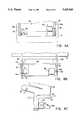
- FIG. 2Awhich is a top view of the improved mobile X-ray apparatus principally illustrating the pivotable movement of the articulating X-ray tube support arm;
- FIG. 2Bwhich is a top view of the improved mobile X-ray apparatus principally illustrating the storage of the X-ray tube and articulating X-ray tube support arm for movement of the apparatus from one location to another;
- FIG. 3Awhich is a perspective view of the trunnion clamp supporting the X-ray tube
- FIG. 3Bwhich is a cross-sectional view of the trunnion clamping mechanism
- FIG. 3Cwhich is a front view of the trunnion clamp supporting the X-ray tube
- FIG. 4Awhich is a top view of the X-ray tube being locked into the cradle of the improved mobile X-ray apparatus carriage;
- FIG. 4Bwhich is a front view of the X-ray tube being locked into the cradle; of the improved mobile X-ray apparatus carriage;
- FIG. 4Cwhich is a side view of the X-ray tube being locked into the cradle of the improved mobile X-ray apparatus carriage;
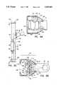
- FIG. 5which is a side view of a portion of the articulating X-ray tube support arm principally illustrating the electro-magnetic multi-disc braking system for preventing relative pivoting of adjacent support arm appendages;
- FIG. 6Awhich is a view of the interior of the top of mast of the improved mobile X-ray apparatus principally illustrating a pulley arrangement
- FIG. 6Bwhich is a cross-sectional view of the mast of the improved mobile X-ray apparatus principally illustrating the rail system for engaging the articulating arm and counterweight therein;
- FIG. 6Cwhich is a schematic view of the counterweighting system within the mast of the improved mobile X-ray apparatus
- FIG. 7Awhich is a top view of the drive carriage of the improved mobile X-ray apparatus, principally illustrating the relative positioning of the motors;
- FIG. 7Bwhich is a front view of the drive carriage of the improved mobile X-ray apparatus, principally illustrating the drive train for rotating the driven wheels;
- FIG. 8which is a cross-sectional view of a driven wheel utilized in the improved mobile X-ray apparatus
- FIG. 9Awhich is a perspective view of a portion of the carriage of the improved mobile X-ray apparatus further illustrating the support of the handle by a pair of strain gage assemblies;
- FIG. 9Bwhich is a top cross-sectional view of the end of the handle illustrating the supporting strain gage assembly engaged with the carriage;
- FIG. 9Cwhich is a side view of the carriage illustrating the engagement of the strain gage with the carriage.
- FIG. 10which is a schematic diagram of the motor drive control circuits.
- a mobile X-ray unitis generally indicated by the numeral 10.
- the mobile X-ray unit 10includes a carriage 12 having a front portion 11, a top 13, a base 14, two opposed sides 15 and a rear portion 16.
- the base 14is supported from the ground by a plurality of wheels comprising a pair of rear driven wheels and a pair of front wheels.
- Right rear driven wheel 17 and right front wheel 19 illustrated in FIG. 1 and a complimentary left hand side pair of wheels (not shown)provide stable support for the carriage 12.
- the mobile X-ray unit 10further includes a mast as generally indicated by the number 20.
- the masthas a front side 21, a rear side 22, two opposed sides 24, a first end 26 and a second end 28.
- Attached to the mast 20is an articulating X-ray tube support arm shown in a fully raised position as generally indicated by the numeral 30.
- the articulating X-ray tube support arm 30is slidable along substantially the entire length of the mast 20.
- a fully lowered illustration of the articulating X-ray tube support arm 30is shown in phantom in FIG. 1 and its fully lowered position is generally indicated by the numeral 31.
- the articulating X-ray tube support arm 30features a plurality of coupled pivotable support appendages that allow an X-ray tube 52 to be moved in planar motion substantially horizontal to the ground supporting the carriage 12.
- the articulating X-ray tube support arm 30comprises a first pivotable support appendage 36 having a first end (not shown) engaged with the mast 20 at the front side 21 and a second end 32.
- a second pivotable support appendage 40also has a first end 41 and a second end 42. The first end 41 of the second pivotable support appendage 40 is pivotally coupled to the second end 38 of the first pivotable support appendage 36.
- the articulating X-ray tube support arm 30also includes a third pivotable support appendage 44 having a first end 45 and a second end 46 and a fourth pivotable support appendage 48 also having a first end 49 and a second end 50.
- the first end 45 of the third pivotable support appendage 44is pivotally coupled to the second end 42 of the second pivotable support appendage 40 while the second end 46 of the third pivotable support appendage 44 is pivotally coupled to the first end 49 of the fourth pivotable support appendage 48.
- the X-ray tube 52is connected to the second end 50 of the fourth pivotable support appendage 48 via a trunnion clamp 54 having a first hoop 55a and a second hoop 55b. Hoops 55a and 55b have aligned radial slots 53a and 53b.
- a pair of rectangular X-ray tube skin guardscomprising a left guard 56a and a right guard 56b are attached to the X-ray tube 52 by well known and ordinary means.
- Right guard 56balso includes a handle portion 59.
- X-ray tube guards 56a and 56b, as well as handle 59,provide an operator with a means for positioning the X-ray tube 52 along the horizontal plane as well as allow the operator to rotate the X-ray tube 52 relative to the trunnion clamp 54 from a first position as shown by the numeral 57 to a second position shown as 58.
- the ordinary skin guards 56a and 56balso serve to protect the collimator assembly (not shown) of the X-ray tube 52 from damage caused by impact as well as ensure that the collimator cannot be placed any closer to the skin than the minimum source to skin distance (SSD), usually 30 cm, permitted by the FDA.
- SSDminimum source to skin distance
- the trunnion clamp 54includes a "quick release” type lever and cam locking system as generally indicated by the numeral 60.
- the lever and cam locking system 60generally comprises a first and second block 70 and 72 respectively attached between trunnion hoops 55a and 55b.
- first block 70is attached to hoops 55a and 55b on one side of aligned slots 53a and 53b while second block 72 is attached to hoops 55a and 55b on the other side of slots 53a and 53b.
- Clamping of the X-ray tube 52is accomplished by drawing first and second blocks 70 and 72 together causing hoops 55a and 55b to become constricted.
- First and second blocks 70 and 72are drawn together by tensioning of an over center pin 66 anchored at one end in the second block 72 by a tension adjusting screw 73. Tension on the over center pin 66 is established by the force of cam 64 and lever 62 connected to the over center pin 66 on a DelrinTM bearing surface 68 adjacent to first block 70.
- lever 62When lever 62 is in an open position as generally illustrated by the numeral 74, the X-ray tube 52 may be rotated within the trunnion hoops 55a and 55b because the hoops are in an unconstricted state and their unconstricted state diameter is larger than that of the X-ray tube 52.
- lever 62When lever 62 is in a closed position as generally illustrated by the numeral 76, the X-ray tube 52 may not be rotated due to the pressure exerted on the tube 52 by hoops 55a and 55b when the hoops are constricted.
- the lever and cam locking system 60thereby provides a quick and convenient means for locking and unlocking the X-ray tube 52 so that the X-ray tube 52 may be precisely rotated by the operator with guards 56a and 56b or handle 59 and then locked in a predetermined position.
- the top portion 13 of the carriage 12includes an X-ray tube cradle 80 having first and second slots 82 and 84 therein.
- a solenoid 86 with associated plunger 88which is of sufficient length to extend substantially across slot 84 when the solenoid is deenergized.
- the body of a limit switch 90is positioned below cradle 80 adjacent to slot 82 such that a portion of a tripping means 92 of the limit switch 90 may extend into slot 82.
- the four pivotable support appendages of the articulating X-ray tube support arm 30, the function of which has been previously discussed,permits the X-ray tube 52 to be pivoted in a manner such that the guards 56a and 56b may be aligned with and placed into slots 82 and 84 of cradle 80.
- limit switch 90When guards 56a and 56b are positioned deep enough within slots 82 and 84 as determined by the contact of guard 56a with protruding tripping means 92 thereby closing limit switch 90, the X-ray tube 52 may be locked in cradle 80 by de-energizing solenoid 86 so that plunger 88 extends substantially across slot 84 when a portion of guard 56b is located below the plunger 88. Also, limit switch 90 may be connected to the general X-ray control circuits (not shown) so as to disable the X-ray tube when contact is made between guard 56a and tripping means 92.
- the articulating X-ray tube support arm 30may also be locked into its resting position as well as any other desired position by a plurality of electromagnetic brakes positioned within the plurality of X-ray tube support arm appendages 36, 40, 44 and 48. An example of such means between two appendages is shown in FIG. 5.
- FIG. 5a portion of second pivotable support appendage 40 and position of third pivotable support appendage 44 are shown pivotally coupled by a shaft 102 which is secured to the second end 42 of second pivotable support appendage 40 by first and second end caps 104 and 106 respectively.
- Smooth rotation of the third pivotable support appendage 44 about shaft 102is provided by bearing sets 105 and 107 positioned between the third pivotable support appendage 44 and first and second end caps 104 and 106 attached to second pivotable support appendage 40.
- an ordinary electromagnetically actuatable multi-disk brake 100 with housing 108is positioned about shaft 102 and within the first end 45 of the third pivotable support appendage 44.
- the multi-disk brake housing 108is attached to the third pivotable support appendage 44.
- a clamp collar 110secures multi-disk brake 100 to shaft 102.
- a spring(not shown) within the brake forces the multiple disks to make contact thereby preventing pivoting movement of the third pivotable support appendage 44 relative to the second pivotable support appendage 40.
- the electro-magnetic forceacts against the spring to allow decoupling of the multiple disks and thereby allow movement of the two adjacent pivotable support appendages 40 and 42.
- Similar electro-magnetic brakesmay be positioned at the pivot points of all of the pivotable support appendages of the articulating X-ray tube support arm 30 to prevent movement thereof.
- An ordinary electro-magnetic actuated multi-disk brake supplied by Inertia Dynamicshas been found to perform satisfactorily for the purposes of immobilizing the articulating X-ray tube support arm 30 of the present invention.
- a switch 71 located on handle 59 electrically connected in an ordinary manner to the brakesmay be used to activate or deactivate them as well as activate or deactivate solenoid 86.
- the use of a brake with single or multiple disks in the practice of the present inventionwill not deviate from its scope.
- FIGS. 1 and 6A through 6Cillustrate the inner workings of the mast 20 and the attachment of the first pivotable support appendage 36 thereto.
- FIG. 6Bwherein the mast 20 is shown in a sectional view, it may be seen that mast 20 is formed as a single extrusion and comprises a first flange 110, a second flange 112 and a web 114, having a first side 116 and a second side 118 connecting the first flange 110 to the second flange 112 much like an 1-beam.
- mast 20it is not necessary for the purposes of the present invention that mast 20 be formed from a single extrusion provided that the mast 20 generally have a pair of flanges and a web as discussed above.
- a first rail 120is attached to the first side 116 of web 114.
- the first rail 120substantially extends from the first end 26 to the second end 28 of the mast 20.
- the first end 37 of pivotable support appendage 36is coupled to rail 120 by a coupling 122 having a plurality of bearings (not shown) surrounding the rail 120.
- Coupling 122permits the first pivotable support appendage 36 and of course the articulating X-ray tube support arm 30, to slide along the mast 20 between the first and second ends 26 and 28 respectively.
- coupling 122may also include a pair of cable anchoring pins 124 and 126 for securing cables to the first pivotable support appendage 36.
- the second side 118 of web 114also includes first and second rail support members 128 and 130 extending outwardly therefrom.
- a pair of rails 132 and 134are attached to the first and second rail support members 128 and 130.
- a counterweight 136is slideably coupled to the rails 132 and 134 by set of couplings containing bearings (not shown) located at the top 137 of counterweight 136 as well as at the bottom 139.
- FIG. 6Billustrates slidable coupling 138 and 140 located at the top 137 of counterweight 136 connecting the counterweight to rails 132 and 134. Bearings in couplings 138 and 140 allow the counterweight 136 to freely slide substantially along the entire length of the mast 20 from the first end 26 to the second end 28.
- the couplings located at the bottom 139 of counterweight 136are arranged in a similar manner to that shown for couplings 138 and 140 in FIG. 6B.
- the four counterweight couplingsslideably secure the counterweight 136 to rails 132 and 134.
- a counterweight system 142 for counterweighting the movement of the first pivotable support appendage 30 along the mast 20is shown in FIG. 6C.
- the first pivotable support appendage 30may be counterweighted by connection to the counterweight 136 by a first cable 144 and a second cable 146.
- One end of first cable 144is attached to anchor 145 located at the second end 28 of the mast 20.
- the first cable 144is routed through an upper counterweight pulley 148 and an upper mast pulley 150 before the other end of the first cable 144 is attached to the first pivotable support appendage 30 at a cable anchor 124.
- one end of the second cable 146is secured to anchor 152 located at the first end 26 of mast 20, and the second cable 146 is routed through lower counterweight pulley 154 and lower mast pulley 156 before its other end is attached to cable anchor 124 of the first pivotable support appendage 20.
- an additional upper mast pulley 158is shown attached to a shaft 160 which is, in turn, connected to upper mast pulley 150. Additional counterweight pulleys and an additional lower mast pulley may be used to guide additional cables in a similar manner to that described for first and second cables 144 and 146.
- the additional cablesprovide redundancy as well as more uniform movement of the counterweight 132 and X-ray tube support arm 30. Also shown on FIG.
- 6Ais an electromagnetic disk brake means 162 connected to shaft 160 that may be used in an ordinary manner to prevent the inadvertent raising and lowering of articulating X-ray tube support arm 30 along mast 20.
- an electric motor 163may be used together with the brake 162 to raise and lower the articulating x-ray tube support arm 30 along mast 20.
- FIGS. 7A, 7B and 8the mobile X-ray apparatus 10 of the present invention is propelled along the floor of a hospital or other similar institution by drive subcarriage 170 attached to the base 14 of carriage 12.
- the drive sub-carriagecomprises a platform 172 on which a pair of electric motors 174 and 176 are positioned so that they lay on the platform substantially between a left driven wheel 178 and the right driven wheel 17.
- the left and right driven wheels 178 and 17are connected to the cart by axle 179 held in position by supports 180 and 182 extending downwardly from sub-carriage platform 172.
- Left and right driven wheels 178 and 17are attached to the axle 179 in a manner that permits them to rotate independently from each other.
- the driven wheels 178 and 17are propelled by motors 174 and 176.
- the propulsionis accomplished via toothed belts 184 and 186 that are connected between gear portions 188 and 190 of the wheels and toothed pulleys 192 and 194 of transmissions 196 and 198 coupled to the shafts of motors 174 and 176.
- the direction and magnitude of rotation of each of the wheels 178 and 17may be independently controlled by associated motor speed and direction control circuits 195 and 197 of the type ordinarily associated with electric motor control.
- the wheels 178 and 17are preferably fabricated as single casting 193 that includes the gear portions 190 wherein a rubber wheel 191 is attached thereto.
- the single casting 193ensures that there are fewer parts to assemble during the manufacturing process and also ensures fewer moving parts that could inadvertently become disassembled possibly causing damage or injury.
- input to motor control circuits 195 and 197is accomplished by placing a force on a handle 200 having first and second ends 202 and 204.
- the first and second ends 202 and 204are positioned within large openings 205 and 207 of first and second projections 206 and 208 located at the rear portion of carriage 12.
- the openings 205 and 207are made to be larger than the width of the handle 200 so as to allow some movement of the handle 200 relative to the carriage 12 when force is applied thereon by an operator.
- a first strain gage assembly 210 located at the first end 202 of handle 200comprises a base 214 and beam 216 attached to the base 214.
- the base 214is mounted within cavity 218 and beam 216 is permitted to extend past the first end 202 of handle 200 into opening 205 and an aperture 220 in the first projection 206 of carriage 12.
- the diameter of aperture 220is intentionally made larger than that of beam 216 so the beam 216 is permitted to have some free play within the aperture 220.
- the second strain gage assembly 212is located at the second end 204 of handle 200.
- the second strain gage assembly 212comprises a base 224 and a beam 226 attached to the base 224.
- Base 224is mounted within cavity 228 so that beam 226 is permitted to extend past the second end 204 of handle 200 into opening 207 and an aperture 230 in the second projection 208 of carriage 12.
- the diameter of aperture 230similar to the diameter of aperture 220, is intentionally made larger than that of beam 226.
- the resilient material 222 together with apertures 220 and 230allow beams 216 and 226 to deflect when contact is made with apertures 220 and 230 but prevent over-deflection and possible binding thereof.
- the resilient material 222also bias the handle 200 to a neutral position so that when no force is applied to handle 200 the beams of strain gage assemblies 210 and 212 are not deflected and thereby no signals are sent by the strain gage assemblies to the control circuits 195 and 197.
- Over-deflection of prior art strain gage handle and carriage assemblies of different designhas been known to cause binding which in turn causes the driven wheels to be inadvertently propelled although the force causing the over-deflection and binding had been removed.
- the interface between the handle 200, strain gage assemblies 210 and 212 and carriage 12 of the present inventionalleviates the problems associated with binding.
- both strain gage assemblies 210 and 212sense the direction and magnitude of relative force placed on handle 200 and appropriately send output signals to the motor speed and direction control circuits 195 and 197.
- input 240 of electric motor 176is connected to output 242 of control circuit 195 and output 244 of strain gage assembly 210 is connected to the input 246 of control circuit 195.
- input 248 of electric motor 174 motoris connected to output 250 of control circuit 197 and output 252 of strain gage assembly 212 is connected to input 254 of control circuit 197.
- both strain gage assemblies 210 and 212are mounted to the handle 200 and each are used to independently control the electric motors 174 and 176, the operator of the mobile X-ray apparatus 10 may virtually control the movement of the apparatus 10 with one hand placed near the middle of the handle 200.
- a bumper 260is positioned at the front 11 of carriage 12. Bumper 260 is attached to a safety cutoff switch 262 that is electrically connected to motor control circuits 195 and 197. Should the bumper 260 strike an obstruction, the switch 262 automatically stops and prevents further forward motion of the drive motors 174 ;and 176 through control circuits 195 and 197. Reverse motion is neither stopped nor prevented by switch 262 so that the apparatus 10 may be backed away from the obstruction.
- handle 200includes brake switch 280 which, when depressed, enables strain gage assemblies 210 and 212 to be responsive to forces applied to handle 200 and thereby allowing control circuits 195 and 197 to propel wheels 178 and 17.
- brake switch 280When brake switch 280 is not depressed, strain gage assemblies 210 and 212 remain unresponsive to the forces applied to handle 200.
- Brake switch 280provides a safety system which prevents inadvertent carriage movement that would otherwise result from unintentional contact with handle 200.
Landscapes
- Health & Medical Sciences (AREA)
- Life Sciences & Earth Sciences (AREA)
- Medical Informatics (AREA)
- Engineering & Computer Science (AREA)
- Radiology & Medical Imaging (AREA)
- Biomedical Technology (AREA)
- Biophysics (AREA)
- Nuclear Medicine, Radiotherapy & Molecular Imaging (AREA)
- Optics & Photonics (AREA)
- Pathology (AREA)
- Physics & Mathematics (AREA)
- High Energy & Nuclear Physics (AREA)
- Heart & Thoracic Surgery (AREA)
- Molecular Biology (AREA)
- Surgery (AREA)
- Animal Behavior & Ethology (AREA)
- General Health & Medical Sciences (AREA)
- Public Health (AREA)
- Veterinary Medicine (AREA)
- Apparatus For Radiation Diagnosis (AREA)
Abstract
Description
Claims (7)
Priority Applications (16)
| Application Number | Priority Date | Filing Date | Title |
|---|---|---|---|
| US08/158,625US5425069A (en) | 1993-11-26 | 1993-11-26 | Mobile X-ray apparatus |
| GB9422394AGB2284331B (en) | 1993-11-26 | 1994-11-07 | Improved mobile X-ray apparatus |
| GB9720406AGB2318266B (en) | 1993-11-26 | 1994-11-07 | Improved Mobile X-Ray Apparatus |
| GB9720405AGB2318265B (en) | 1993-11-26 | 1994-11-07 | Improved Mobile X-Ray Apparatus |
| DE4447728ADE4447728C2 (en) | 1993-11-26 | 1994-11-19 | Mobile X=ray appts for hospitals nursing homes etc |
| DE4447727ADE4447727C2 (en) | 1993-11-26 | 1994-11-19 | Mobile x-ray device |
| DE4447856ADE4447856C2 (en) | 1993-11-26 | 1994-11-19 | Mobile x-ray device |
| DE4441236ADE4441236C2 (en) | 1993-11-26 | 1994-11-19 | Mobile x-ray device |
| CA002259633ACA2259633C (en) | 1993-11-26 | 1994-11-25 | Improved mobile x-ray apparatus |
| CA002261105ACA2261105C (en) | 1993-11-26 | 1994-11-25 | Improved mobile x-ray apparatus |
| FR9414177AFR2712796B1 (en) | 1993-11-26 | 1994-11-25 | Advanced mobile X-ray device. |
| CA002136708ACA2136708C (en) | 1993-11-26 | 1994-11-25 | Mobile x-ray apparatus |
| US08/400,288US5499284A (en) | 1993-11-26 | 1995-03-03 | Mobile X-ray apparatus |
| FR9504878AFR2716613B1 (en) | 1993-11-26 | 1995-04-24 | Advanced mobile X-ray device. |
| FR9504879AFR2716614B1 (en) | 1993-11-26 | 1995-04-24 | Advanced mobile X-ray device. |
| FR9910634AFR2780629B1 (en) | 1993-11-26 | 1999-08-19 | IMPROVED X-RAY MOBILE APPARATUS |
Applications Claiming Priority (1)
| Application Number | Priority Date | Filing Date | Title |
|---|---|---|---|
| US08/158,625US5425069A (en) | 1993-11-26 | 1993-11-26 | Mobile X-ray apparatus |
Related Child Applications (1)
| Application Number | Title | Priority Date | Filing Date |
|---|---|---|---|
| US08/400,288DivisionUS5499284A (en) | 1993-11-26 | 1995-03-03 | Mobile X-ray apparatus |
Publications (1)
| Publication Number | Publication Date |
|---|---|
| US5425069Atrue US5425069A (en) | 1995-06-13 |
Family
ID=22568990
Family Applications (2)
| Application Number | Title | Priority Date | Filing Date |
|---|---|---|---|
| US08/158,625Expired - Fee RelatedUS5425069A (en) | 1993-11-26 | 1993-11-26 | Mobile X-ray apparatus |
| US08/400,288Expired - Fee RelatedUS5499284A (en) | 1993-11-26 | 1995-03-03 | Mobile X-ray apparatus |
Family Applications After (1)
| Application Number | Title | Priority Date | Filing Date |
|---|---|---|---|
| US08/400,288Expired - Fee RelatedUS5499284A (en) | 1993-11-26 | 1995-03-03 | Mobile X-ray apparatus |
Country Status (4)
| Country | Link |
|---|---|
| US (2) | US5425069A (en) |
| CA (1) | CA2136708C (en) |
| FR (2) | FR2712796B1 (en) |
| GB (1) | GB2284331B (en) |
Cited By (45)
| Publication number | Priority date | Publication date | Assignee | Title |
|---|---|---|---|---|
| US5499284A (en)* | 1993-11-26 | 1996-03-12 | Thermotrex Corporation | Mobile X-ray apparatus |
| US5540296A (en)* | 1993-07-24 | 1996-07-30 | Strothmann; Rolf | Electric auxiliary drive for a travelling device primarily driven, in particular drawn or pushed, by human or animal power |
| WO2000032459A1 (en)* | 1998-11-28 | 2000-06-08 | Sociedad Española De Electromedicina Y Calidad, S.A. | System for controlling electric motors used for the propulsion of a transport trolley |
| US6131690A (en)* | 1998-05-29 | 2000-10-17 | Galando; John | Motorized support for imaging means |
| US6155367A (en)* | 1998-03-21 | 2000-12-05 | Ulrich Alber Gmbh & Co. Kg | Drive assistance device for a hand-driven wheel chair |
| WO2001030635A1 (en)* | 1999-10-26 | 2001-05-03 | John Galando | Improved motorized support for imaging means and methods of manufacture and use thereof |
| US6237707B1 (en) | 1999-02-18 | 2001-05-29 | Hologic, Inc. | Motion controlling system for motorized medical equipment carriage |
| US6568850B2 (en) | 2001-03-22 | 2003-05-27 | Siemens Elema Ab | X-ray imaging system |
| US20030223549A1 (en)* | 2001-11-23 | 2003-12-04 | Robin Winsor | Positioning stand for a radiography imaging device |
| US20030230698A1 (en)* | 2002-05-18 | 2003-12-18 | Wolfgang Strauss | Carrier system for a medical apparatus |
| US6705758B1 (en) | 1999-06-30 | 2004-03-16 | Instrumntarium Corp. | Steering arrangement for mobile x-ray apparatus |
| US20040086083A1 (en)* | 2001-09-06 | 2004-05-06 | Peter Bier | Imaging medical examination apparatus |
| US20040146142A1 (en)* | 2003-01-29 | 2004-07-29 | Miikka Maijala | Mobile X-ray apparatus |
| US20050084074A1 (en)* | 2003-10-21 | 2005-04-21 | Muthuvelan Varadharajulu | Table control method, patient supporting device, and X-ray imaging apparatus |
| US20070080580A1 (en)* | 2005-09-30 | 2007-04-12 | General Electric Company | Braking control method and system for a positioner in a medical imaging apparatus |
| US20070183588A1 (en)* | 2004-07-30 | 2007-08-09 | Bailey Eric M | Mobile Computerized Tomography (CT) imaging system with cordless and wireless capabilities |
| US20080022780A1 (en)* | 2006-07-31 | 2008-01-31 | General Electric Company | Method and system for impact detection of an imaging system |
| US20090080598A1 (en)* | 2007-09-26 | 2009-03-26 | University Of Pittsburgh - Of The Commonwealth System Of Higher Education | Bi-plane x-ray imaging system |
| US20090310753A1 (en)* | 2008-06-12 | 2009-12-17 | Matthew Aaron Halsmer | Method and apparatus for driving a mobile imaging system |
| US20110096910A1 (en)* | 2009-10-23 | 2011-04-28 | Shaohua Yao | X-ray imaging system |
| WO2011130214A2 (en) | 2010-04-13 | 2011-10-20 | Carestream Health, Inc. | Counterweight for mobile x-ray device |
| WO2011130203A3 (en)* | 2010-04-13 | 2012-02-23 | Carestream Health, Inc. | Collapsible column movement apparatus for mobile x-ray device |
| US8172242B1 (en) | 2008-03-06 | 2012-05-08 | Thomas Crandall | Medical imaging workstation |
| WO2012087129A1 (en) | 2010-12-22 | 2012-06-28 | Nucletron Operations B.V. | A mobile x-ray unit |
| CN102648855A (en)* | 2011-02-24 | 2012-08-29 | 西门子公司 | Arm support device for a mobile c-arm x-ray machine |
| US20130064351A1 (en)* | 2011-09-12 | 2013-03-14 | Carestream Health, Inc. | Charger for electronic grid holders and detectors stored at mobile radiographic imaging apparatus and methods for using the same |
| US8692140B1 (en)* | 2013-03-15 | 2014-04-08 | Surgitrac Corporation | Surgical object and fluid monitoring system having highly sensitive and reliable detection of objects being placed in a container |
| US20140105358A1 (en)* | 2012-10-12 | 2014-04-17 | Canon Kabushiki Kaisha | Mobile x-ray generation apparatus and mobile x-ray imaging system |
| US20140233705A1 (en)* | 2013-02-19 | 2014-08-21 | Canon Kabushiki Kaisha | Mobile x-ray imaging apparatus |
| US20140291540A1 (en)* | 2013-03-29 | 2014-10-02 | Canon Kabushiki Kaisha | Radiation generating apparatus and radiographic imaging system |
| WO2014158079A1 (en)* | 2013-03-27 | 2014-10-02 | Adolesco Ab | Mobile medical imaging system |
| US8963025B2 (en)* | 2013-03-15 | 2015-02-24 | Surgitrac Corporation | Surgical object and fluid monitoring system having highly sensitive and reliable detection of objects being placed in a container |
| CN104458770A (en)* | 2013-09-13 | 2015-03-25 | 青岛天盾橡胶有限公司 | Portable mining giant radial tire carcass nondestructive testing detector |
| US9084582B2 (en)* | 2012-09-28 | 2015-07-21 | Canon Kabushiki Kaisha | Radiation imaging apparatus and method of controlling radiation imaging apparatus |
| US9125611B2 (en) | 2010-12-13 | 2015-09-08 | Orthoscan, Inc. | Mobile fluoroscopic imaging system |
| US9173620B2 (en) | 2012-04-16 | 2015-11-03 | Neurologica Corp. | Imaging system with rigidly mounted fiducial markers |
| US9347817B2 (en) | 2013-03-15 | 2016-05-24 | Surgitrac Corporation | Surgical object and comprehensive fluid monitoring system having capability of mobile monitoring and having highly sensitive and reliable detection of objects being placed in a container |
| US9480445B2 (en) | 2013-05-14 | 2016-11-01 | Solutions For Tomorrow Ab | Elevating column and method of controlling elevation thereof |
| US10136954B2 (en) | 2012-06-21 | 2018-11-27 | Globus Medical, Inc. | Surgical tool systems and method |
| US20210145385A1 (en)* | 2016-02-03 | 2021-05-20 | Globus Medical, Inc. | Portable medical imaging system |
| US11058378B2 (en) | 2016-02-03 | 2021-07-13 | Globus Medical, Inc. | Portable medical imaging system |
| US11272893B2 (en) | 2019-07-09 | 2022-03-15 | Carestream Health, Inc. | Collapsible column movement apparatus for mobile x-ray device |
| US20230038131A1 (en)* | 2021-08-05 | 2023-02-09 | GE Precision Healthcare LLC | Suspension device and x-ray imaging system |
| CN116747461A (en)* | 2023-08-15 | 2023-09-15 | 成都利尼科医学技术发展有限公司 | Medical accelerator airborne image device |
| WO2024079456A1 (en)* | 2022-10-14 | 2024-04-18 | Xstrahl Limited | Improvements in or relating to medical device apparatus |
Families Citing this family (22)
| Publication number | Priority date | Publication date | Assignee | Title |
|---|---|---|---|---|
| US5784435A (en)* | 1997-04-23 | 1998-07-21 | General Electric Company | X-ray tube support column on a mobile x-ray product with improved rotational flexibility |
| JP3412620B2 (en)* | 2000-03-28 | 2003-06-03 | 株式会社島津製作所 | X-ray equipment for round examination |
| US7113162B1 (en)* | 2000-05-12 | 2006-09-26 | Bradley D. Beasley | Digital radiograph analyzer and methods |
| DE10051459A1 (en)* | 2000-10-17 | 2002-03-28 | Siemens Ag | X-ray set for medical use has an X-ray source that can be tilted upwards into a park position, when not in use, to allow complete access to a patient lying below it |
| US6702459B2 (en)* | 2001-04-11 | 2004-03-09 | The Uab Research Foundation | Mobile radiography system and process |
| US6733177B2 (en)* | 2002-09-12 | 2004-05-11 | Ge Medical Systems Global Technology Company, Llc | Friction ring for improved orbital balance of C-arm x-ray apparatus |
| US7319738B2 (en)* | 2004-10-08 | 2008-01-15 | General Electric Company | Delivering X-ray systems to pipe installations |
| KR100719341B1 (en)* | 2005-01-25 | 2007-05-17 | 삼성전자주식회사 | Image sensor and its manufacturing method |
| US7581884B1 (en) | 2006-02-07 | 2009-09-01 | Barnes Gary T | Mobile radiography system and grid alignment process |
| JP5508019B2 (en)* | 2006-11-16 | 2014-05-28 | コーニンクレッカ フィリップス エヌ ヴェ | Foldable nuclear medicine gantry |
| US7802642B2 (en)* | 2006-11-22 | 2010-09-28 | General Electric Company | Systems, methods and apparatus of motorised independent main-wheel drive and positioning for a mobile imaging system |
| US8033724B2 (en)* | 2009-06-30 | 2011-10-11 | The Boeing Company | Rapid assembly and operation of an X-ray imaging system |
| US20110249806A1 (en)* | 2010-04-13 | 2011-10-13 | Wendlandt William C | Mobile radiography unit having collapsible support column |
| JP5661180B2 (en) | 2010-06-25 | 2015-01-28 | ヴァリアン メディカル システムズ インコーポレイテッド | Remodeling kit and remodeling method for current portable or movable analog X-ray imaging apparatus and X-ray diagnostic apparatus equipped with the remodeling kit to enable application of digital X-ray imaging |
| US10165992B2 (en) | 2010-10-18 | 2019-01-01 | Carestream Health, Inc. | X-ray imaging systems and devices |
| NL2005898C2 (en)* | 2010-12-22 | 2012-06-25 | Nucletron Bv | A mobile x-ray unit. |
| NL2005904C2 (en)* | 2010-12-22 | 2012-06-25 | Nucletron Bv | A mobile x-ray unit. |
| JP2014079275A (en)* | 2012-10-12 | 2014-05-08 | Canon Inc | Movable x-ray generator and movable x-ray imaging system |
| US10271802B2 (en)* | 2014-08-12 | 2019-04-30 | Carestream Health, Inc. | Digital x-ray imaging apparatus and method |
| JP6859898B2 (en)* | 2017-08-25 | 2021-04-14 | 株式会社島津製作所 | Mobile radiography device |
| US10674974B1 (en) | 2018-11-23 | 2020-06-09 | Turner Imaging Systems, Inc. | Clamping mechanism for a portable X-ray imaging device |
| US10856822B2 (en) | 2018-11-23 | 2020-12-08 | Turner Imaging Systems, Inc. | Clamping device for a portable X-ray imaging device |
Citations (22)
| Publication number | Priority date | Publication date | Assignee | Title |
|---|---|---|---|---|
| US2051508A (en)* | 1933-03-23 | 1936-08-18 | Philips Nv | Support for light sources |
| US2113866A (en)* | 1936-09-02 | 1938-04-12 | Thurlow E Mcfall | X-ray machine |
| US2556909A (en)* | 1946-09-07 | 1951-06-12 | Kelley Koett Mfg Co | X-ray apparatus |
| US2846587A (en)* | 1956-04-27 | 1958-08-05 | Raymond C Thurow | X-ray fixator |
| US3025401A (en)* | 1957-10-28 | 1962-03-13 | Ritter Co Inc | Control panel for X-ray unit |
| US3644735A (en)* | 1969-12-31 | 1972-02-22 | Litton Medical Products | Leveling mechanism for x-ray machines |
| US3702935A (en)* | 1971-10-13 | 1972-11-14 | Litton Medical Products | Mobile fluoroscopic unit for bedside catheter placement |
| US3790805A (en)* | 1971-04-19 | 1974-02-05 | Picker Corp | Mobile x-ray unit |
| US3801790A (en)* | 1972-03-15 | 1974-04-02 | Siemens Ag | Movable x-ray examining device |
| US4113042A (en)* | 1976-11-01 | 1978-09-12 | Westinghouse Electric Corp. | Manual control handle for electric vehicle |
| US4166602A (en)* | 1978-05-18 | 1979-09-04 | Pennwalt Corporation | Counterbalancing mechanism for X-ray tubeheads |
| US4322623A (en)* | 1980-05-05 | 1982-03-30 | Grady John K | Mobile X-ray apparatus |
| US4326131A (en)* | 1977-10-03 | 1982-04-20 | Siemens Aktiengesellschaft | Mobile x-ray apparatus |
| US4387468A (en)* | 1981-10-09 | 1983-06-07 | Techny Industries, Inc. | Mobile X-ray apparatus |
| US4590378A (en)* | 1984-06-04 | 1986-05-20 | Siemens Gammasonics, Inc. | Counterbalanced radiation detection device |
| US4646862A (en)* | 1984-08-28 | 1987-03-03 | Internationale Octropi | Floor cleaning machine |
| US4697661A (en)* | 1986-07-14 | 1987-10-06 | General Electric Company | Drive design for mobile x-ray units with dual wheel drives |
| US4752948A (en)* | 1986-12-01 | 1988-06-21 | University Of Chicago | Mobile radiography alignment device |
| US4989229A (en)* | 1989-11-22 | 1991-01-29 | Picker International, Inc. | Counterbalance assembly for diagnostic imaging equipment |
| US5008921A (en)* | 1988-10-11 | 1991-04-16 | Siemens Aktiengesellschaft | Portable x-ray diagnostics apparatus with position-adjustable control panel |
| US5067145A (en)* | 1990-03-16 | 1991-11-19 | Siczek Bernard W | Mobile X-ray apparatus |
| US5081662A (en)* | 1989-06-28 | 1992-01-14 | Siemens Aktiengesellschaft | Mobile x-ray apparatus |
Family Cites Families (12)
| Publication number | Priority date | Publication date | Assignee | Title |
|---|---|---|---|---|
| US427474A (en)* | 1890-05-06 | Hydrocarbon device for burning off paint | ||
| US2036097A (en)* | 1932-11-10 | 1936-03-31 | Alphonse F Pieper | Counterbalanced supporting mechanism |
| GB563890A (en)* | 1942-12-24 | 1944-09-04 | Siemens Schuckert Great Britai | Improvements in x-ray apparatus |
| GB675065A (en)* | 1949-05-27 | 1952-07-02 | Newton Victor Ltd | Improvements relating to x-ray apparatus |
| US2737596A (en)* | 1950-10-28 | 1956-03-06 | Keleket X Ray Corp | X-ray apparatus |
| US4196630A (en)* | 1978-05-18 | 1980-04-08 | Rudolph Dale C | Overhead arm assembly |
| US4223222A (en)* | 1978-09-28 | 1980-09-16 | General Electric Company | Suspended arm for a scintillation camera |
| EP0068931A3 (en)* | 1981-06-10 | 1983-10-26 | Thomson-Csf | Coupling device between a tube support and a frame |
| US4548373A (en)* | 1983-03-22 | 1985-10-22 | Tokyo Kogaku Kikai Kabushiki Kaisha | Medical equipment supporting device |
| US4695024A (en)* | 1986-05-09 | 1987-09-22 | Attain, Inc. | Test system manipulator arm |
| DE4202922A1 (en)* | 1992-02-01 | 1993-08-05 | Zeiss Carl Fa | MOTORIC TRIPOD |
| US5425069A (en)* | 1993-11-26 | 1995-06-13 | Lorad Corporation | Mobile X-ray apparatus |
- 1993
- 1993-11-26USUS08/158,625patent/US5425069A/ennot_activeExpired - Fee Related
- 1994
- 1994-11-07GBGB9422394Apatent/GB2284331B/ennot_activeExpired - Fee Related
- 1994-11-25CACA002136708Apatent/CA2136708C/ennot_activeExpired - Fee Related
- 1994-11-25FRFR9414177Apatent/FR2712796B1/ennot_activeExpired - Fee Related
- 1995
- 1995-03-03USUS08/400,288patent/US5499284A/ennot_activeExpired - Fee Related
- 1999
- 1999-08-19FRFR9910634Apatent/FR2780629B1/ennot_activeExpired - Fee Related
Patent Citations (22)
| Publication number | Priority date | Publication date | Assignee | Title |
|---|---|---|---|---|
| US2051508A (en)* | 1933-03-23 | 1936-08-18 | Philips Nv | Support for light sources |
| US2113866A (en)* | 1936-09-02 | 1938-04-12 | Thurlow E Mcfall | X-ray machine |
| US2556909A (en)* | 1946-09-07 | 1951-06-12 | Kelley Koett Mfg Co | X-ray apparatus |
| US2846587A (en)* | 1956-04-27 | 1958-08-05 | Raymond C Thurow | X-ray fixator |
| US3025401A (en)* | 1957-10-28 | 1962-03-13 | Ritter Co Inc | Control panel for X-ray unit |
| US3644735A (en)* | 1969-12-31 | 1972-02-22 | Litton Medical Products | Leveling mechanism for x-ray machines |
| US3790805A (en)* | 1971-04-19 | 1974-02-05 | Picker Corp | Mobile x-ray unit |
| US3702935A (en)* | 1971-10-13 | 1972-11-14 | Litton Medical Products | Mobile fluoroscopic unit for bedside catheter placement |
| US3801790A (en)* | 1972-03-15 | 1974-04-02 | Siemens Ag | Movable x-ray examining device |
| US4113042A (en)* | 1976-11-01 | 1978-09-12 | Westinghouse Electric Corp. | Manual control handle for electric vehicle |
| US4326131A (en)* | 1977-10-03 | 1982-04-20 | Siemens Aktiengesellschaft | Mobile x-ray apparatus |
| US4166602A (en)* | 1978-05-18 | 1979-09-04 | Pennwalt Corporation | Counterbalancing mechanism for X-ray tubeheads |
| US4322623A (en)* | 1980-05-05 | 1982-03-30 | Grady John K | Mobile X-ray apparatus |
| US4387468A (en)* | 1981-10-09 | 1983-06-07 | Techny Industries, Inc. | Mobile X-ray apparatus |
| US4590378A (en)* | 1984-06-04 | 1986-05-20 | Siemens Gammasonics, Inc. | Counterbalanced radiation detection device |
| US4646862A (en)* | 1984-08-28 | 1987-03-03 | Internationale Octropi | Floor cleaning machine |
| US4697661A (en)* | 1986-07-14 | 1987-10-06 | General Electric Company | Drive design for mobile x-ray units with dual wheel drives |
| US4752948A (en)* | 1986-12-01 | 1988-06-21 | University Of Chicago | Mobile radiography alignment device |
| US5008921A (en)* | 1988-10-11 | 1991-04-16 | Siemens Aktiengesellschaft | Portable x-ray diagnostics apparatus with position-adjustable control panel |
| US5081662A (en)* | 1989-06-28 | 1992-01-14 | Siemens Aktiengesellschaft | Mobile x-ray apparatus |
| US4989229A (en)* | 1989-11-22 | 1991-01-29 | Picker International, Inc. | Counterbalance assembly for diagnostic imaging equipment |
| US5067145A (en)* | 1990-03-16 | 1991-11-19 | Siczek Bernard W | Mobile X-ray apparatus |
Non-Patent Citations (14)
| Title |
|---|
| Kramex Model SCD 125 Mobile X Ray Unit . . . , No Date.* |
| Kramex Model SCD-125 Mobile X-Ray Unit . . . , No Date. |
| Kramex Model: SCD 105 Mobile X Ray Unit . . . , No Date.* |
| Kramex Model: SCD-105 Mobile X-Ray Unit . . . , No Date. |
| Kramex SCD 105 Condenser Discharge Mobile X Ray Unit, No Date.* |
| Kramex SCD 125 Condenser Discharge Mobile X Ray Unit, No date.* |
| Kramex SCD-105 Condenser Discharge Mobile X-Ray Unit, No Date. |
| Kramex SCD-125 Condenser Discharge Mobile X-Ray Unit, No date. |
| Picker Explorer II Mobile X Ray System, 1989, GE Medical Systems AMX 4 Mobile X Ray System, 1987.* |
| Picker Explorer II Mobile X-Ray System, 1989, GE Medical Systems AMX-4 Mobile X-Ray System, 1987. |
| Picker Explorer, Setting New Standards In Mobile X Ray Performance, No Date.* |
| Picker Explorer, Setting New Standards In Mobile X-Ray Performance, No Date. |
| Shimadzu Medical Systems Brochure, MC125L 50, Cordless Mobile X Ray, No Date.* |
| Shimadzu Medical Systems Brochure, MC125L-50, Cordless Mobile X-Ray, No Date. |
Cited By (78)
| Publication number | Priority date | Publication date | Assignee | Title |
|---|---|---|---|---|
| US5540296A (en)* | 1993-07-24 | 1996-07-30 | Strothmann; Rolf | Electric auxiliary drive for a travelling device primarily driven, in particular drawn or pushed, by human or animal power |
| US5499284A (en)* | 1993-11-26 | 1996-03-12 | Thermotrex Corporation | Mobile X-ray apparatus |
| US6155367A (en)* | 1998-03-21 | 2000-12-05 | Ulrich Alber Gmbh & Co. Kg | Drive assistance device for a hand-driven wheel chair |
| US6374937B1 (en) | 1998-05-29 | 2002-04-23 | John Galando | Motorized support for imaging means and methods of manufacture and use thereof |
| US6131690A (en)* | 1998-05-29 | 2000-10-17 | Galando; John | Motorized support for imaging means |
| US6871715B1 (en)* | 1998-11-28 | 2005-03-29 | Sociedad Espanola De Electromedicina Y Calidad, S.A. | System for controlling electric motors used for the propulsion of a transport trolley |
| ES2146553A1 (en)* | 1998-11-28 | 2000-08-01 | Electromedicina Y Calidad S A | System for controlling electric motors used for the propulsion of a transport trolley |
| WO2000032459A1 (en)* | 1998-11-28 | 2000-06-08 | Sociedad Española De Electromedicina Y Calidad, S.A. | System for controlling electric motors used for the propulsion of a transport trolley |
| US6237707B1 (en) | 1999-02-18 | 2001-05-29 | Hologic, Inc. | Motion controlling system for motorized medical equipment carriage |
| US6705758B1 (en) | 1999-06-30 | 2004-03-16 | Instrumntarium Corp. | Steering arrangement for mobile x-ray apparatus |
| WO2001030635A1 (en)* | 1999-10-26 | 2001-05-03 | John Galando | Improved motorized support for imaging means and methods of manufacture and use thereof |
| US6568850B2 (en) | 2001-03-22 | 2003-05-27 | Siemens Elema Ab | X-ray imaging system |
| US20040086083A1 (en)* | 2001-09-06 | 2004-05-06 | Peter Bier | Imaging medical examination apparatus |
| US20030223549A1 (en)* | 2001-11-23 | 2003-12-04 | Robin Winsor | Positioning stand for a radiography imaging device |
| US20030230698A1 (en)* | 2002-05-18 | 2003-12-18 | Wolfgang Strauss | Carrier system for a medical apparatus |
| US7219864B2 (en) | 2002-05-18 | 2007-05-22 | Carl-Zeiss-Stiftung | Carrier system for a medical apparatus |
| US6899307B2 (en)* | 2002-05-18 | 2005-05-31 | Carl-Zeiss-Stiftung | Carrier system for a medical apparatus |
| US20070012853A1 (en)* | 2002-05-18 | 2007-01-18 | Carl-Zeiss-Stiftung | Carrier system for a medical apparatus |
| US20040146142A1 (en)* | 2003-01-29 | 2004-07-29 | Miikka Maijala | Mobile X-ray apparatus |
| US20050084074A1 (en)* | 2003-10-21 | 2005-04-21 | Muthuvelan Varadharajulu | Table control method, patient supporting device, and X-ray imaging apparatus |
| US7186024B2 (en)* | 2003-10-21 | 2007-03-06 | Ge Medical Systems Global Technology Company, Llc | Table control method, patient supporting device, and X-ray imaging apparatus |
| US20070183588A1 (en)* | 2004-07-30 | 2007-08-09 | Bailey Eric M | Mobile Computerized Tomography (CT) imaging system with cordless and wireless capabilities |
| US7397895B2 (en)* | 2004-07-30 | 2008-07-08 | Neurologica Corp. | Mobile computerized tomography (CT) imaging system with cordless and wireless capabilities |
| US8177307B2 (en)* | 2005-09-30 | 2012-05-15 | General Electric Company | Braking control method and system for a positioner in a medical imaging apparatus |
| US20070080580A1 (en)* | 2005-09-30 | 2007-04-12 | General Electric Company | Braking control method and system for a positioner in a medical imaging apparatus |
| US20080022780A1 (en)* | 2006-07-31 | 2008-01-31 | General Electric Company | Method and system for impact detection of an imaging system |
| US7377172B2 (en)* | 2006-07-31 | 2008-05-27 | General Electric Company | Method and system for impact detection of an imaging system |
| US7806589B2 (en)* | 2007-09-26 | 2010-10-05 | University Of Pittsburgh | Bi-plane X-ray imaging system |
| US20090080598A1 (en)* | 2007-09-26 | 2009-03-26 | University Of Pittsburgh - Of The Commonwealth System Of Higher Education | Bi-plane x-ray imaging system |
| US8172242B1 (en) | 2008-03-06 | 2012-05-08 | Thomas Crandall | Medical imaging workstation |
| CN101606844A (en)* | 2008-06-12 | 2009-12-23 | 通用电气公司 | Method and apparatus for driving a mobile imaging system |
| CN101606844B (en)* | 2008-06-12 | 2013-07-31 | 通用电气公司 | Method and apparatus for driving a mobile imaging system |
| US7682077B2 (en)* | 2008-06-12 | 2010-03-23 | General Electric Company | Method and apparatus for driving a mobile imaging system |
| US20090310753A1 (en)* | 2008-06-12 | 2009-12-17 | Matthew Aaron Halsmer | Method and apparatus for driving a mobile imaging system |
| US20110096910A1 (en)* | 2009-10-23 | 2011-04-28 | Shaohua Yao | X-ray imaging system |
| US8636410B2 (en)* | 2009-10-23 | 2014-01-28 | Ge Medical Systems Global Technology Company, Llc | Mobile X-ray imaging system including a steering mechanism and a brake mechanism |
| WO2011130203A3 (en)* | 2010-04-13 | 2012-02-23 | Carestream Health, Inc. | Collapsible column movement apparatus for mobile x-ray device |
| US8876379B2 (en) | 2010-04-13 | 2014-11-04 | Carestream Health, Inc. | Collapsible column movement apparatus for mobile x-ray device |
| CN102834053A (en)* | 2010-04-13 | 2012-12-19 | 卡尔斯特里姆保健公司 | Counterweight for mobile x-ray device |
| WO2011130214A3 (en)* | 2010-04-13 | 2012-02-23 | Carestream Health, Inc. | Counterweight for mobile x-ray device |
| WO2011130214A2 (en) | 2010-04-13 | 2011-10-20 | Carestream Health, Inc. | Counterweight for mobile x-ray device |
| US8672543B2 (en)* | 2010-04-13 | 2014-03-18 | Carestream Health, Inc. | Counterweight for mobile x-ray device |
| CN102834053B (en)* | 2010-04-13 | 2015-11-25 | 卡尔斯特里姆保健公司 | For the counterweight of mobile X-ray apparatus |
| US10178978B2 (en) | 2010-12-13 | 2019-01-15 | Orthoscan, Inc. | Mobile fluoroscopic imaging system |
| US9833206B2 (en) | 2010-12-13 | 2017-12-05 | Orthoscan, Inc. | Mobile fluoroscopic imaging system |
| US9125611B2 (en) | 2010-12-13 | 2015-09-08 | Orthoscan, Inc. | Mobile fluoroscopic imaging system |
| WO2012087129A1 (en) | 2010-12-22 | 2012-06-28 | Nucletron Operations B.V. | A mobile x-ray unit |
| CN102648855B (en)* | 2011-02-24 | 2015-11-18 | 西门子公司 | The spinning solution of rotatable C arm supporting arrangement and C arm supporting arrangement |
| CN102648855A (en)* | 2011-02-24 | 2012-08-29 | 西门子公司 | Arm support device for a mobile c-arm x-ray machine |
| US9839406B2 (en) | 2011-09-12 | 2017-12-12 | Carestream Health, Inc. | Charger for electronic grid holders and detectors stored at mobile radiographic imaging apparatus and methods for using the same |
| US20130064351A1 (en)* | 2011-09-12 | 2013-03-14 | Carestream Health, Inc. | Charger for electronic grid holders and detectors stored at mobile radiographic imaging apparatus and methods for using the same |
| US9414802B2 (en)* | 2011-09-12 | 2016-08-16 | Carestream Health, Inc. | Charger for electronic grid holders and detectors stored at mobile radiographic imaging apparatus and methods for using the same |
| US9173620B2 (en) | 2012-04-16 | 2015-11-03 | Neurologica Corp. | Imaging system with rigidly mounted fiducial markers |
| US11439471B2 (en) | 2012-06-21 | 2022-09-13 | Globus Medical, Inc. | Surgical tool system and method |
| US10136954B2 (en) | 2012-06-21 | 2018-11-27 | Globus Medical, Inc. | Surgical tool systems and method |
| US9084582B2 (en)* | 2012-09-28 | 2015-07-21 | Canon Kabushiki Kaisha | Radiation imaging apparatus and method of controlling radiation imaging apparatus |
| US20140105358A1 (en)* | 2012-10-12 | 2014-04-17 | Canon Kabushiki Kaisha | Mobile x-ray generation apparatus and mobile x-ray imaging system |
| US20140233705A1 (en)* | 2013-02-19 | 2014-08-21 | Canon Kabushiki Kaisha | Mobile x-ray imaging apparatus |
| US9414794B2 (en)* | 2013-02-19 | 2016-08-16 | Canon Kabushiki Kaisha | Mobile X-ray imaging apparatus |
| US8692140B1 (en)* | 2013-03-15 | 2014-04-08 | Surgitrac Corporation | Surgical object and fluid monitoring system having highly sensitive and reliable detection of objects being placed in a container |
| US8963025B2 (en)* | 2013-03-15 | 2015-02-24 | Surgitrac Corporation | Surgical object and fluid monitoring system having highly sensitive and reliable detection of objects being placed in a container |
| US9347817B2 (en) | 2013-03-15 | 2016-05-24 | Surgitrac Corporation | Surgical object and comprehensive fluid monitoring system having capability of mobile monitoring and having highly sensitive and reliable detection of objects being placed in a container |
| WO2014158079A1 (en)* | 2013-03-27 | 2014-10-02 | Adolesco Ab | Mobile medical imaging system |
| US20140291540A1 (en)* | 2013-03-29 | 2014-10-02 | Canon Kabushiki Kaisha | Radiation generating apparatus and radiographic imaging system |
| US9480445B2 (en) | 2013-05-14 | 2016-11-01 | Solutions For Tomorrow Ab | Elevating column and method of controlling elevation thereof |
| CN104458770A (en)* | 2013-09-13 | 2015-03-25 | 青岛天盾橡胶有限公司 | Portable mining giant radial tire carcass nondestructive testing detector |
| US20210145385A1 (en)* | 2016-02-03 | 2021-05-20 | Globus Medical, Inc. | Portable medical imaging system |
| US11058378B2 (en) | 2016-02-03 | 2021-07-13 | Globus Medical, Inc. | Portable medical imaging system |
| US11523784B2 (en)* | 2016-02-03 | 2022-12-13 | Globus Medical, Inc. | Portable medical imaging system |
| US20230080203A1 (en)* | 2016-02-03 | 2023-03-16 | Globus Medical, Inc. | Portable medical imaging system |
| US12016714B2 (en)* | 2016-02-03 | 2024-06-25 | Globus Medical Inc. | Portable medical imaging system |
| US20240298985A1 (en)* | 2016-02-03 | 2024-09-12 | Globus Medical, Inc. | Portable medical imaging system |
| US11272893B2 (en) | 2019-07-09 | 2022-03-15 | Carestream Health, Inc. | Collapsible column movement apparatus for mobile x-ray device |
| US20230038131A1 (en)* | 2021-08-05 | 2023-02-09 | GE Precision Healthcare LLC | Suspension device and x-ray imaging system |
| US12268540B2 (en)* | 2021-08-05 | 2025-04-08 | GE Precision Healthcare LLC | Suspension device and x-ray imaging system |
| WO2024079456A1 (en)* | 2022-10-14 | 2024-04-18 | Xstrahl Limited | Improvements in or relating to medical device apparatus |
| CN116747461A (en)* | 2023-08-15 | 2023-09-15 | 成都利尼科医学技术发展有限公司 | Medical accelerator airborne image device |
| CN116747461B (en)* | 2023-08-15 | 2023-10-31 | 成都利尼科医学技术发展有限公司 | Medical accelerator airborne image device |
Also Published As
| Publication number | Publication date |
|---|---|
| FR2780629A1 (en) | 2000-01-07 |
| FR2712796B1 (en) | 2000-03-17 |
| GB2284331B (en) | 1998-06-17 |
| FR2712796A1 (en) | 1995-06-02 |
| CA2136708A1 (en) | 1995-05-27 |
| FR2780629B1 (en) | 2003-10-10 |
| GB2284331A (en) | 1995-05-31 |
| US5499284A (en) | 1996-03-12 |
| CA2136708C (en) | 1999-06-08 |
| GB9422394D0 (en) | 1995-01-04 |
Similar Documents
| Publication | Publication Date | Title |
|---|---|---|
| US5425069A (en) | Mobile X-ray apparatus | |
| US5499415A (en) | Stabilized, cantilevered, patient trauma table system | |
| US10987491B2 (en) | Robotic catheter system | |
| US10583276B2 (en) | Catheter system with magnetic coupling | |
| US9185301B2 (en) | Drive system for imaging device | |
| US4387468A (en) | Mobile X-ray apparatus | |
| US6782571B1 (en) | Patient transport system for multiple imaging systems | |
| US5475885A (en) | Couch system for x-ray diagnosis | |
| EP0248537B1 (en) | A therapeutic bed | |
| EP2454994B1 (en) | Portable X-ray machine with drive wheel suspension | |
| JPS62183746A (en) | X-ray diagnostic apparatus | |
| US6789940B2 (en) | Medical X-ray examination device | |
| US20220061779A9 (en) | Caster System For Mobile Apparatus | |
| US4082955A (en) | X-ray apparatus | |
| CA2261105C (en) | Improved mobile x-ray apparatus | |
| GB2318266A (en) | Driving a mobile X-ray apparatus | |
| US4845734A (en) | Expandable carriage for spot-film device | |
| US5313961A (en) | Movable medical examination chair | |
| US11737934B2 (en) | MRI compatible patient trolley | |
| JP5041731B2 (en) | Safe motion enabling sequence and system for medical imaging devices | |
| JP3578513B2 (en) | X-ray diagnostic equipment | |
| US20250152443A1 (en) | Mri compatible air management system |
Legal Events
| Date | Code | Title | Description |
|---|---|---|---|
| AS | Assignment | Owner name:LORAD CORPORATION, CONNECTICUT Free format text:ASSIGNMENT OF ASSIGNORS INTEREST;ASSIGNORS:PELLEGRINO, ANTHONY J.;DEFREITAS, KENNETH F.;LYKE, DANIEL N.;AND OTHERS;REEL/FRAME:006855/0231 Effective date:19931217 | |
| AS | Assignment | Owner name:THERMOTREX CORPORATION, CALIFORNIA Free format text:MERGER;ASSIGNOR:LORAD CORPORATION;REEL/FRAME:007162/0977 Effective date:19940627 | |
| AS | Assignment | Owner name:TREX MEDICAL CORPORATION, CONNECTICUT Free format text:ASSIGNMENT OF ASSIGNORS INTEREST;ASSIGNOR:THERMOTREX CORPORATION;REEL/FRAME:008392/0975 Effective date:19970228 | |
| FEPP | Fee payment procedure | Free format text:PAYOR NUMBER ASSIGNED (ORIGINAL EVENT CODE: ASPN); ENTITY STATUS OF PATENT OWNER: LARGE ENTITY | |
| FPAY | Fee payment | Year of fee payment:4 | |
| AS | Assignment | Owner name:HOLOGIC, INC., MASSACHUSETTS Free format text:ASSIGNMENT OF ASSIGNORS INTEREST;ASSIGNOR:TREX MEDICAL SYSTEMS CORPORATION;REEL/FRAME:011442/0560 Effective date:20000915 | |
| AS | Assignment | Owner name:TREX MEDICAL SYSTEMS CORPORATION, CONNECTICUT Free format text:ASSIGNMENT OF ASSIGNORS INTEREST;ASSIGNOR:TREX MEDICAL CORPORATION;REEL/FRAME:012280/0579 Effective date:20000910 | |
| FPAY | Fee payment | Year of fee payment:8 | |
| SULP | Surcharge for late payment | Year of fee payment:7 | |
| REMI | Maintenance fee reminder mailed | ||
| REMI | Maintenance fee reminder mailed | ||
| LAPS | Lapse for failure to pay maintenance fees | ||
| STCH | Information on status: patent discontinuation | Free format text:PATENT EXPIRED DUE TO NONPAYMENT OF MAINTENANCE FEES UNDER 37 CFR 1.362 | |
| FP | Lapsed due to failure to pay maintenance fee | Effective date:20070613 |