US5425000A - Spatial rejection of direct blast interference in multistatic sonars - Google Patents
Spatial rejection of direct blast interference in multistatic sonarsDownload PDFInfo
- Publication number
- US5425000A US5425000AUS08/169,887US16988793AUS5425000AUS 5425000 AUS5425000 AUS 5425000AUS 16988793 AUS16988793 AUS 16988793AUS 5425000 AUS5425000 AUS 5425000A
- Authority
- US
- United States
- Prior art keywords
- beamformer
- gain
- output signals
- beamformer output
- direct blast
- Prior art date
- Legal status (The legal status is an assumption and is not a legal conclusion. Google has not performed a legal analysis and makes no representation as to the accuracy of the status listed.)
- Expired - Lifetime
Links
- 230000003111delayed effectEffects0.000claimsabstractdescription13
- 230000001052transient effectEffects0.000claimsdescription26
- 238000001514detection methodMethods0.000claimsdescription24
- 238000000034methodMethods0.000claimsdescription22
- 238000012545processingMethods0.000claimsdescription19
- 230000004044responseEffects0.000claimsdescription14
- 230000001629suppressionEffects0.000claimsdescription5
- 230000002238attenuated effectEffects0.000claimsdescription3
- 230000004043responsivenessEffects0.000claims3
- RUZYUOTYCVRMRZ-UHFFFAOYSA-NdoxazosinChemical compoundC1OC2=CC=CC=C2OC1C(=O)N(CC1)CCN1C1=NC(N)=C(C=C(C(OC)=C2)OC)C2=N1RUZYUOTYCVRMRZ-UHFFFAOYSA-N0.000claims2
- 230000003044adaptive effectEffects0.000description4
- 238000010586diagramMethods0.000description2
- 238000002592echocardiographyMethods0.000description2
- 230000000694effectsEffects0.000description2
- 238000012935AveragingMethods0.000description1
- 238000013459approachMethods0.000description1
- 238000003491arrayMethods0.000description1
- 230000009286beneficial effectEffects0.000description1
- 230000005540biological transmissionEffects0.000description1
- 238000004364calculation methodMethods0.000description1
- 230000001934delayEffects0.000description1
- 230000002939deleterious effectEffects0.000description1
- 238000013461designMethods0.000description1
- 230000000873masking effectEffects0.000description1
- 238000005259measurementMethods0.000description1
- 230000001902propagating effectEffects0.000description1
- 238000012360testing methodMethods0.000description1
Images


Classifications
- G—PHYSICS
- G01—MEASURING; TESTING
- G01S—RADIO DIRECTION-FINDING; RADIO NAVIGATION; DETERMINING DISTANCE OR VELOCITY BY USE OF RADIO WAVES; LOCATING OR PRESENCE-DETECTING BY USE OF THE REFLECTION OR RERADIATION OF RADIO WAVES; ANALOGOUS ARRANGEMENTS USING OTHER WAVES
- G01S7/00—Details of systems according to groups G01S13/00, G01S15/00, G01S17/00
- G01S7/52—Details of systems according to groups G01S13/00, G01S15/00, G01S17/00 of systems according to group G01S15/00
- G01S7/523—Details of pulse systems
- G01S7/526—Receivers
- G01S7/529—Gain of receiver varied automatically during pulse-recurrence period
- G—PHYSICS
- G01—MEASURING; TESTING
- G01S—RADIO DIRECTION-FINDING; RADIO NAVIGATION; DETERMINING DISTANCE OR VELOCITY BY USE OF RADIO WAVES; LOCATING OR PRESENCE-DETECTING BY USE OF THE REFLECTION OR RERADIATION OF RADIO WAVES; ANALOGOUS ARRANGEMENTS USING OTHER WAVES
- G01S15/00—Systems using the reflection or reradiation of acoustic waves, e.g. sonar systems
- G01S15/87—Combinations of sonar systems
- G—PHYSICS
- G01—MEASURING; TESTING
- G01S—RADIO DIRECTION-FINDING; RADIO NAVIGATION; DETERMINING DISTANCE OR VELOCITY BY USE OF RADIO WAVES; LOCATING OR PRESENCE-DETECTING BY USE OF THE REFLECTION OR RERADIATION OF RADIO WAVES; ANALOGOUS ARRANGEMENTS USING OTHER WAVES
- G01S13/00—Systems using the reflection or reradiation of radio waves, e.g. radar systems; Analogous systems using reflection or reradiation of waves whose nature or wavelength is irrelevant or unspecified
- G01S13/003—Bistatic radar systems; Multistatic radar systems
- Y—GENERAL TAGGING OF NEW TECHNOLOGICAL DEVELOPMENTS; GENERAL TAGGING OF CROSS-SECTIONAL TECHNOLOGIES SPANNING OVER SEVERAL SECTIONS OF THE IPC; TECHNICAL SUBJECTS COVERED BY FORMER USPC CROSS-REFERENCE ART COLLECTIONS [XRACs] AND DIGESTS
- Y10—TECHNICAL SUBJECTS COVERED BY FORMER USPC
- Y10S—TECHNICAL SUBJECTS COVERED BY FORMER USPC CROSS-REFERENCE ART COLLECTIONS [XRACs] AND DIGESTS
- Y10S367/00—Communications, electrical: acoustic wave systems and devices
- Y10S367/90—Sonar time varied gain control systems
- Y—GENERAL TAGGING OF NEW TECHNOLOGICAL DEVELOPMENTS; GENERAL TAGGING OF CROSS-SECTIONAL TECHNOLOGIES SPANNING OVER SEVERAL SECTIONS OF THE IPC; TECHNICAL SUBJECTS COVERED BY FORMER USPC CROSS-REFERENCE ART COLLECTIONS [XRACs] AND DIGESTS
- Y10—TECHNICAL SUBJECTS COVERED BY FORMER USPC
- Y10S—TECHNICAL SUBJECTS COVERED BY FORMER USPC CROSS-REFERENCE ART COLLECTIONS [XRACs] AND DIGESTS
- Y10S367/00—Communications, electrical: acoustic wave systems and devices
- Y10S367/901—Noise or unwanted signal reduction in nonseismic receiving system
Definitions
- the present :inventionrelates to active sonar systems, and more particularly to an apparatus and method of spatial rejection of direct blast interference in multistatic sonars.
- the transmitterIn bistatic and multistatic active sonars, used e.g., for tactical and surveillance applications, the transmitter is located at an appreciable distance from the receiver. The distance between the source and the receiver is generally much less than the length of the sound path from the source to the target to the receiver. The arrival of the transmitted waveform at the receiver directly from the transmitter, known as the "direct blast,” is therefore much stronger than the target echo. Typical geometries show the direct blast to be 40 to 60 dB above typical target echoes. The direct blast can arrive simultaneously with echoes of previously transmitted waveforms from targets at ranges of interest, preventing their detection.
- spatial processing applicationsdeal with interferences that are continuous (rather than pulsed like active waveforms), and much lower in level.
- a "spatial transient,” occurring when the waveform leading or trailing edge is propagating across the array,can result in signal masking even when a spatial null is steered in the direction of the source. This transient is many dB below the overall direct blast level, but may still mask the signal because the direct blast level is 40-60 dB above the signal.
- Spatial processing techniquesattempt to reduce the level of the direct blast when it arrives from a different angle than the target of interest.
- the spatial transientis still strong enough to limit detection of many signals.
- the spatial transientis a unique phenomenon related to the direct blast in multistatic systems (or other transient interferences many orders of magnitude larger than the signal of interest).
- Conventional spatial rejection techniqueswhether adaptive or fixed parameter approaches, will exhibit the spatial transient and will not, therefore, effectively reject these strong interferences to a degree which allows detection of a signal 40-60 dB lower in level.
- the effects of direct blastcan be reduced by several techniques.
- the sonarcan be operated in range-doppler bins other than that containing the direct blast when the signal to be detected is an echo of the same waveform as the direct blast. While it cannot be guaranteed that the target will appear at a different doppler than the direct blast, the ability to operate in other range bins greatly reduces the deleterious effect of the direct blast.
- the rejection of the direct blast in range-doppler bins sufficiently far from the blast in frequencycan be on the order of 36 dB for waveforms typically used in these systems.
- Another technique for reducing direct blast interferenceis to use a series of waveforms with low cross-ambiguity, so that a direct blast due to one waveform is reduced by the matched filter used to detect the echo of another waveform.
- PCWPulsed Continuous Wave
- HARMHyperbolic Frequency Modulated
- the cross-ambiguity of typical low frequency sonar waveformsis on the order of 20-25 dB, but can be as low as 10 dB.
- Transmitting successive waveforms in separate receiver sub bands with very good out of band rejectioncan also be used to reduce direct blast interference. If the direct blast and the received echo fall in different sub bands, the direct blast level is reduced by the out of band rejection relative to the signal. Practical considerations limit the number of sub bands in a given system to a relatively small number.
- Spatial rejectionreduces the direct blast level provided the source and target arrive from different directions.
- Thisis implemented in a beamformer, which achieves a directional response in the direction of the signal by computing a weighted sum of the delayed (or weighted) hydrophone outputs, with the delays and weights selected to yield the desired spatial response.
- Conventional beamformersmaximize the response in the signal direction while reducing the response in all other directions to less than the sidelobe level. Practical systems achieve sidelobe levels of 20-25 dB.
- rejection of interferencesis often achieved by steering of spatial nulls in the direction of the interference if the location of the interference is known with sufficient accuracy, or by means of various adaptive techniques which effectively steer a null if the interference is strong enough.
- Similar techniqueshave been used in active sonars to reject strong, continuous interferences or interferences whose duration is long in comparison to that of the transmitted waveform.
- the interference durationis nominally the same as that of the echo, and the direct blast-to-noise ratio is much higher than interference-to-noise ratios generally encountered. The combination of these differences results in an effect in the spatial processing that differs from cases usually considered.
- the very high interference-to-noise ratio associated with the direct blastrequires some changes to conventional spatial processing techniques, it does allow accurate determination of the location of the arrival direction of the direct blast.
- a multi-static sonar system having direct blast interference suppressionincludes a sonar transmitter, a sonar transmit transducer array, a sonar receive transducer array spatially separated from the transmit array, and a null steering beamformer coupled to the receiver array for forming one or more receive beams in one or more desired directions, for forming a null response beam in a nominal direction of the transmit array from the receive array, and for providing beamformer output signals.
- the systemfurther includes automatic gain control (AGC) means for applying variable gain to the beamformer output signals.
- AGCautomatic gain control
- the AGC variable gainhas a first value in all cases except when a level of the beamformer output signals exceeds a predetermined threshold value, Thus, the gain is substantially reduced to a relatively smaller second value for a predetermined time interval at the leading and trailing edges of received direct blast interference from the transmit array to suppress spatial transients occurring in the beamformer output signal at the leading and trailing edges of the direct blast.
- the systemfurther includes processing means for processing the output of the AGC to provide a sonar system output signal.
- the first gain value of the AGCis preferably unity, and the second gain value is much less than unity.
- the AGCcomprises delay means for delaying the beamformer output signals by a delay interval, means for providing an estimate of the output power in an undelayed sample of the beamformer output signal, means for normalizing the delayed output signal by the power estimate, and means for comparing the normalized output signal to said threshold value.
- the beamformer output signalsare in the form of digitized data samples
- the delay meansis a digital delay line
- the normalizing meansincludes a means for determining the squared value of undelayed versions of the samples, and means for providing an average value of the squared values over a time window.
- a method for suppressing direct blast interference in a multi-static sonar systemincluding a sonar receive transducer array spatially separated from a transmit source, and a null steering beamformer coupled to said receive array for forming one or more receive beams in one or more desired directions, comprising a sequence of the following steps:
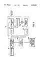
- FIG. 1illustrates direct blast propagation through an array of sensors.
- FIG. 2shows a bi-static sonar system embodying the present invention.
- FIG. 3is a simplified schematic diagram illustrating the automatic gain control function of the system of FIG. 2.
- FIG. 4is an exemplary beam pattern for a particular sonar system array embodying the invention, showing a notch formed with three nulls.
- FIG. 5is a simplified schematic diagram showing a frequency domain implementation of a beamformer useful in a bi-static sonar system in accordance with the invention.
- An active sonar systemtypically employs matched filter detection at the output of a beamformer. Examination of the matched filter input has revealed why the direct blast is not more completely rejected. At the leading and trailing edges of the direct blast, a large spike of energy will "leak" through the beamformer null. These spikes are short in duration, on the order of 0.01 times the duration of the direct blast, so that the energy in the spikes is 20 dB down from the total direct blast energy. However, because the direct blast is 40-60 dB above the signal the leakage is sufficient to obscure the signal.
- the direct blast component of the beamformer outputconsists of the hydrophone output times the weight value.
- the weightsare designed to steer a null when the entire array is illuminated.
- the beamformerdoes not effectively steer a null in the direction of the direct blast until the array is "filled.”
- the nullis not properly steered as the waveform propagates out of the array.
- spatial transientsThe duration of the spatial transients is therefore related to the time it takes for the waveform to fill the array, and hence, to the array length and the arrival angle of the target.
- the receiverIn multistatic sonars, the receiver generally uses very long line arrays, and the source is substantially away from the array broadside.
- the bi-static system of FIG. 2includes a transmitter 52 connected to a transmit array 54 of hydrophones, for transmission of an active sonar waveform.
- a receive array 56 of hydrophones, spatially separated from the transmit array 54,is connected to a beamformer 58.
- the beamformer outputis in turn passed through the AGC 60 in accordance with the invention to the matched filter 62.
- the magnitude of the output of the matched filteris squared at function 64, normalized by normalizer 66, and subjected to a threshold detection test at detector 68. It will be understood that the array 50, less the AGC 60, is otherwise conventional.
- the AGC 60is illustrated in further detail in FIG. 3, and is controlled by a normalizer comprising function blocks 60D and 60E which computes an estimate of the power in a window preceding the current beamformer output sample and uses it to normalize the current output.
- the output of the beamformer (58)is delayed by a delay line (60A) before being passed through a programmable gain (60B).
- the magnitude of an undelayed version of the beamformer outputis squared (60D) and averaged over a time window (60E).
- the function of the comparator 60Cis to detect the direct blast transient, by comparing a delayed version of the beamformer output to the threshold ay. If the delayed output x of the beamformer is greater than the threshold, a direct blast transient is detected. In this event, the time varying gain of variable gain/attenuation device 60B is set to G ⁇ 1 to scale down the beamformer output.
- the gain of the AGC 60is unity in all cases except when the normalized beamformer output power exceeds a threshold, T p .
- T pWhen the threshold is exceeded, the gain is reduced to G ⁇ 1 for a duration of ⁇ seconds centered around the point at which the threshold is exceeded.
- the value of ⁇is typically set to slightly exceed the transient duration, which is a function of the size of the array. The objective is to determine when the spatial transients exist in the output and reduce their level to be comparable to the signal level.
- the power in the spatial transients at the AGC outputis P DB G 2 /H, which is set small enough to allow detection of the signal. Since a signal arriving from another direction is passed by the beamformer, its power is attenuated by at most
- Tis the waveform duration. This attenuation, A s , is only slightly less than unity given that G ⁇ 1 and ⁇ T.
- the direct blast spatial rejection technique in accordance with the inventiontherefore uses a beamformer notch steered in the nominal direction of the source by a weight calculation 58B, with the weights selected in dependence on the nominal source direction data provided by the direct blast processor 58A.
- Such a notchis constructed by placing a series of nulls close together over the desired notch width, as shown in FIG. 4.
- 3 nullsare equally spaced over a 3° sector to produce the notch.
- the nullsare steered using linear constraints as described in "An Algorithm for Linearly Constrained Adaptive Array Processing," O. L. Frost, Proceedings of the IEEE, Vol. 60, No. 8, August 1972, but any method of steering nulls in a desired direction will suffice.
- Use of a notchhas a beneficial effect on the performance of this direct blast spatial rejection when the beamformer is implemented in the frequency domain in a practical system.
- a frequency domain implementationis the most effective way to implement a beamformer which must maintain multiple spatial constraints, especially nulls, over a frequency band.
- the nullWhen implemented in the frequency domain in a digital (sampled) system, as shown in FIG. 5, the null is designed at the center of each Fast Fourier Transform (FFT) bin by multiplying each hydrophone in each bin by a complex coefficient.
- FFTFast Fourier Transform
- the nullis only steered in the designated direction when the signal falls at a bin center frequency. Because typically nulls are quite sharp, small frequency differences from bin center significantly reduce direct blast attenuation, and with the high direct blast levels, signal detectability is reduced. Because doppler shift on the direct blast is not known exactly, even with the single frequency (pulsed continuous wave, PCW) signals cannot be maintained at bin center.
Landscapes
- Engineering & Computer Science (AREA)
- Radar, Positioning & Navigation (AREA)
- Remote Sensing (AREA)
- Computer Networks & Wireless Communication (AREA)
- Physics & Mathematics (AREA)
- General Physics & Mathematics (AREA)
- Measurement Of Velocity Or Position Using Acoustic Or Ultrasonic Waves (AREA)
Abstract
Description
.sub.0 (n)=(|x(n)|.sup.2)/(P(n))
A.sub.s =[1-2 (τ/T) (1-G.sup.2)]
Claims (31)
Priority Applications (1)
| Application Number | Priority Date | Filing Date | Title |
|---|---|---|---|
| US08/169,887US5425000A (en) | 1993-12-16 | 1993-12-16 | Spatial rejection of direct blast interference in multistatic sonars |
Applications Claiming Priority (1)
| Application Number | Priority Date | Filing Date | Title |
|---|---|---|---|
| US08/169,887US5425000A (en) | 1993-12-16 | 1993-12-16 | Spatial rejection of direct blast interference in multistatic sonars |
Publications (1)
| Publication Number | Publication Date |
|---|---|
| US5425000Atrue US5425000A (en) | 1995-06-13 |
Family
ID=22617622
Family Applications (1)
| Application Number | Title | Priority Date | Filing Date |
|---|---|---|---|
| US08/169,887Expired - LifetimeUS5425000A (en) | 1993-12-16 | 1993-12-16 | Spatial rejection of direct blast interference in multistatic sonars |
Country Status (1)
| Country | Link |
|---|---|
| US (1) | US5425000A (en) |
Cited By (16)
| Publication number | Priority date | Publication date | Assignee | Title |
|---|---|---|---|---|
| FR2767587A1 (en)* | 1997-08-25 | 1999-02-26 | Imra Europe Sa | METHOD FOR IMPROVING SOUND DETECTION AND DETERMINING THE POSITION OF SMALL TARGETS |
| US5933446A (en)* | 1991-05-29 | 1999-08-03 | The United States Of America As Represented By The Secretary Of The Navy | Beamformer with adaptive processors |
| EP1176428A1 (en)* | 2000-07-26 | 2002-01-30 | STN ATLAS Elektronik GmbH | Method for improving the signal-to-noise ratio of a sonar array |
| US6661740B1 (en)* | 2002-06-03 | 2003-12-09 | Ben R. Breed | Multi-static, opportune-source-exploiting, passive sonar processing |
| US6782063B1 (en)* | 2000-09-12 | 2004-08-24 | The United States Of America As Represented By The Secretary Of The Navy | Automatic gain control |
| WO2005024461A1 (en)* | 2003-09-04 | 2005-03-17 | Sonartech Atlas Pty Ltd | Resolving directional information in sonar arrays |
| US20060083110A1 (en)* | 2004-10-19 | 2006-04-20 | Tietjen Byron W | Ambient bistatic echo ranging system and method |
| US20070073630A1 (en)* | 2004-09-17 | 2007-03-29 | Todd Greene | Fraud analyst smart cookie |
| US7263143B1 (en)* | 2001-05-07 | 2007-08-28 | Adaptix, Inc. | System and method for statistically directing automatic gain control |
| US20090296526A1 (en)* | 2008-06-02 | 2009-12-03 | Kabushiki Kaisha Toshiba | Acoustic treatment apparatus and method thereof |
| US20140241240A1 (en)* | 2013-02-28 | 2014-08-28 | Cisco Technology, Inc. | Distributed Processing Distributed-Input Distributed-Output (DIDO) Wireless Communication |
| US9668149B1 (en) | 2016-05-25 | 2017-05-30 | Cisco Technology, Inc. | Receiver stomp-and-restart in a distributed MU-MIMO system using RSSI separation |
| US10306675B2 (en) | 2017-05-03 | 2019-05-28 | Cisco Technology, Inc. | Collision detection and avoidance mechanism using distributed radio heads in a wireless network |
| US10312979B2 (en) | 2016-07-27 | 2019-06-04 | Cisco Technology, Inc. | Enabling distributed access points on high bandwidth cables for band and antenna splitting |
| US20230106766A1 (en)* | 2021-10-05 | 2023-04-06 | Qualcomm Incorporated | Nulling for inter-user equipment interference cancellation |
| US20240283496A1 (en)* | 2023-02-22 | 2024-08-22 | The Boeing Company | Adaptive signal forming for radio frequency spectrum sharing with interference suppression |
Citations (3)
| Publication number | Priority date | Publication date | Assignee | Title |
|---|---|---|---|---|
| US3763490A (en)* | 1971-12-10 | 1973-10-02 | Gen Electric | Adaptive beamformer with time constant control |
| US4316270A (en)* | 1978-09-08 | 1982-02-16 | Westinghouse Canada Limited | Digital time-delay beamformer for sonar systems |
| US5251185A (en)* | 1992-10-15 | 1993-10-05 | Raytheon Company | Sonar signal processor and display |
- 1993
- 1993-12-16USUS08/169,887patent/US5425000A/ennot_activeExpired - Lifetime
Patent Citations (3)
| Publication number | Priority date | Publication date | Assignee | Title |
|---|---|---|---|---|
| US3763490A (en)* | 1971-12-10 | 1973-10-02 | Gen Electric | Adaptive beamformer with time constant control |
| US4316270A (en)* | 1978-09-08 | 1982-02-16 | Westinghouse Canada Limited | Digital time-delay beamformer for sonar systems |
| US5251185A (en)* | 1992-10-15 | 1993-10-05 | Raytheon Company | Sonar signal processor and display |
Non-Patent Citations (2)
| Title |
|---|
| "An Algorithm for Linearly Constrained Adaptive Array Processing," O. L. Frost, Proceedings of the IEEE, vol. 60, No. 8, Aug. 1972. |
| An Algorithm for Linearly Constrained Adaptive Array Processing, O. L. Frost, Proceedings of the IEEE, vol. 60, No. 8, Aug. 1972.* |
Cited By (23)
| Publication number | Priority date | Publication date | Assignee | Title |
|---|---|---|---|---|
| US5933446A (en)* | 1991-05-29 | 1999-08-03 | The United States Of America As Represented By The Secretary Of The Navy | Beamformer with adaptive processors |
| EP0899579A1 (en)* | 1997-08-25 | 1999-03-03 | Imra Europe S.A. | Method for improving the acoustical detection and positioning of small targets |
| FR2767587A1 (en)* | 1997-08-25 | 1999-02-26 | Imra Europe Sa | METHOD FOR IMPROVING SOUND DETECTION AND DETERMINING THE POSITION OF SMALL TARGETS |
| EP1176428A1 (en)* | 2000-07-26 | 2002-01-30 | STN ATLAS Elektronik GmbH | Method for improving the signal-to-noise ratio of a sonar array |
| US6782063B1 (en)* | 2000-09-12 | 2004-08-24 | The United States Of America As Represented By The Secretary Of The Navy | Automatic gain control |
| US7263143B1 (en)* | 2001-05-07 | 2007-08-28 | Adaptix, Inc. | System and method for statistically directing automatic gain control |
| US6661740B1 (en)* | 2002-06-03 | 2003-12-09 | Ben R. Breed | Multi-static, opportune-source-exploiting, passive sonar processing |
| WO2005024461A1 (en)* | 2003-09-04 | 2005-03-17 | Sonartech Atlas Pty Ltd | Resolving directional information in sonar arrays |
| US20070008821A1 (en)* | 2003-09-04 | 2007-01-11 | Rory Niland | Resolving directional information in sonar arrays |
| US7289389B2 (en) | 2003-09-04 | 2007-10-30 | Sonartech Atlas Pty Ltd | Resolving directional information in sonar arrays |
| US20070073630A1 (en)* | 2004-09-17 | 2007-03-29 | Todd Greene | Fraud analyst smart cookie |
| US20060083110A1 (en)* | 2004-10-19 | 2006-04-20 | Tietjen Byron W | Ambient bistatic echo ranging system and method |
| US20090296526A1 (en)* | 2008-06-02 | 2009-12-03 | Kabushiki Kaisha Toshiba | Acoustic treatment apparatus and method thereof |
| US8120993B2 (en)* | 2008-06-02 | 2012-02-21 | Kabushiki Kaisha Toshiba | Acoustic treatment apparatus and method thereof |
| US20140241240A1 (en)* | 2013-02-28 | 2014-08-28 | Cisco Technology, Inc. | Distributed Processing Distributed-Input Distributed-Output (DIDO) Wireless Communication |
| US9241275B2 (en)* | 2013-02-28 | 2016-01-19 | Cisco Technologies, Inc. | Distributed processing distributed-input distributed-output (DIDO) wireless communication |
| US9668149B1 (en) | 2016-05-25 | 2017-05-30 | Cisco Technology, Inc. | Receiver stomp-and-restart in a distributed MU-MIMO system using RSSI separation |
| US9929792B2 (en) | 2016-05-25 | 2018-03-27 | Cisco Technology, Inc. | Receiver stomp-and-restart in a distributed MU-MIMO system using RSSI separation |
| US10312979B2 (en) | 2016-07-27 | 2019-06-04 | Cisco Technology, Inc. | Enabling distributed access points on high bandwidth cables for band and antenna splitting |
| US10601475B2 (en) | 2016-07-27 | 2020-03-24 | Cisco Technology, Inc. | Enabling distributed access points on high bandwidth cables for band and antenna splitting |
| US10306675B2 (en) | 2017-05-03 | 2019-05-28 | Cisco Technology, Inc. | Collision detection and avoidance mechanism using distributed radio heads in a wireless network |
| US20230106766A1 (en)* | 2021-10-05 | 2023-04-06 | Qualcomm Incorporated | Nulling for inter-user equipment interference cancellation |
| US20240283496A1 (en)* | 2023-02-22 | 2024-08-22 | The Boeing Company | Adaptive signal forming for radio frequency spectrum sharing with interference suppression |
Similar Documents
| Publication | Publication Date | Title |
|---|---|---|
| CA2540596C (en) | Sonar system and process | |
| US7403153B2 (en) | System and method for reducing a radar interference signal | |
| US5425000A (en) | Spatial rejection of direct blast interference in multistatic sonars | |
| US7683827B2 (en) | System and method for reducing the effect of a radar interference signal | |
| US6809682B1 (en) | Method and device for the detection and track of targets in high clutter | |
| US5122990A (en) | Bottom tracking system | |
| US4339754A (en) | Spatially adaptive moving target indicator system for radar equipment | |
| US5311189A (en) | Method for distinguishing between at least two targets | |
| Shapir et al. | Doppler ambiguity resolving in TDMA automotive MIMO radar via digital multiple PRF | |
| US4654835A (en) | Adaptive predictor of surface reverberation in a bistatic sonar | |
| WO2010039299A1 (en) | Counter target acquisition radar and acoustic adjunct for classification | |
| US4622556A (en) | Technique for rapid determination of probability of detection in pulse doppler radars | |
| EP2317335A1 (en) | Improved beamforming method for analysing signals received by a transducer arrray, and relative detection system | |
| EP0527571B1 (en) | Sensitivity velocity control | |
| US20070247351A1 (en) | Wideband Radar | |
| Dawe | Detection threshold modelling explained | |
| US20200033467A1 (en) | Method of measuring azimuth of radar target | |
| Barger | Sonar systems | |
| KR100493727B1 (en) | Method for detecting target in multi-function radar | |
| US9170320B1 (en) | Transmitter pushing compensation for radar stability enhancement | |
| JP3287784B2 (en) | Radar equipment | |
| EP4345499A1 (en) | Two-way radar beam pattern steering | |
| JPH0310080B2 (en) | ||
| KR102391935B1 (en) | Apparatus and method for estimating angle of the low velocity target in the radar | |
| JP2643514B2 (en) | Radar signal processor |
Legal Events
| Date | Code | Title | Description |
|---|---|---|---|
| AS | Assignment | Owner name:HUGHES AIRCRAFT COMPANY, CALIFORNIA Free format text:ASSIGNMENT OF ASSIGNORS INTEREST;ASSIGNORS:REED, FRANCIS A.;THAI, PAUL H.;REEL/FRAME:006829/0417 Effective date:19931215 | |
| STCF | Information on status: patent grant | Free format text:PATENTED CASE | |
| FPAY | Fee payment | Year of fee payment:4 | |
| SULP | Surcharge for late payment | ||
| REMI | Maintenance fee reminder mailed | ||
| FEPP | Fee payment procedure | Free format text:PAYOR NUMBER ASSIGNED (ORIGINAL EVENT CODE: ASPN); ENTITY STATUS OF PATENT OWNER: LARGE ENTITY | |
| FPAY | Fee payment | Year of fee payment:8 | |
| AS | Assignment | Owner name:HE HOLDINGS, INC., A DELAWARE CORP., CALIFORNIA Free format text:CHANGE OF NAME;ASSIGNOR:HUGHES AIRCRAFT COMPANY, A CORPORATION OF THE STATE OF DELAWARE;REEL/FRAME:016087/0541 Effective date:19971217 Owner name:RAYTHEON COMPANY, MASSACHUSETTS Free format text:MERGER;ASSIGNOR:HE HOLDINGS, INC. DBA HUGHES ELECTRONICS;REEL/FRAME:016116/0506 Effective date:19971217 | |
| FPAY | Fee payment | Year of fee payment:12 | |
| FEPP | Fee payment procedure | Free format text:PAYER NUMBER DE-ASSIGNED (ORIGINAL EVENT CODE: RMPN); ENTITY STATUS OF PATENT OWNER: LARGE ENTITY Free format text:PAYOR NUMBER ASSIGNED (ORIGINAL EVENT CODE: ASPN); ENTITY STATUS OF PATENT OWNER: LARGE ENTITY | |
| AS | Assignment | Owner name:OL SECURITY LIMITED LIABILITY COMPANY, DELAWARE Free format text:ASSIGNMENT OF ASSIGNORS INTEREST;ASSIGNOR:RAYTHEON COMPANY;REEL/FRAME:029117/0335 Effective date:20120730 |